1
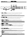
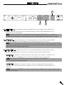
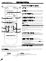
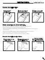
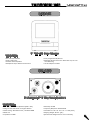
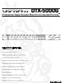
DTX-5000G FEATURES:
• CDG+Decoder/Pre-Amp
• 11-Step 32-Bit DSP Key Controller
• 3-Microphone Channels w/XLR and 1/4" Input Jacks
• Professional Digital Echo/Repeat/Delay
• Vocal Eliminator Eliminates or Reduces the Vocals on any CD
• Variable Outputs (Allows Direct Connection to Amp)
• Full-function Remote Control to Operate all Features
• On-Screen Display shows all Remote-Control settings
• 3-Audio/Video Inputs
• 2-Switchable Digital Inputs w/Optical and Coaxial Jacks
• NTSC/PAL for both U.S. and European TVs
• Dimensions : 19-1/4” (L) x 10-1/5” (D) x 5” (H)
Owner’s Manual
V. 1
SAFETY INSTRUCTIONS
9.
RISK OF ELECTRIC SHOCK
DO NOT OPEN
To reduce the risk of electric shock, do
not remove cover (or back). No user-serviceable parts inside. Only
refer servicing to qualified service personnel.
• Explanation of Graphical Symbols
The lightning flash & arrowhead symbol,
within an equilateral triangle, is intended
to alert you to the presence of danger.
The exclamation point within an
equilateral triangle is intended to alert you to
the presence of important operating and servicing instructions.
WARNING
Heat - The appliance should be situated away from
heat sources such as radiators, heat registers,
stoves, or other appliances (including amplifiers)
that produce heat.
10. Power Sources - The appliance should be connected
to a power supply only of the type described in the
operating instructions or as marked on
the appliance.
11. Grounding or Polarization – Precautions should be
taken so that the grounding or polarization means of
an appliance is not defeated.
12. Power-Cord Protection – Power-supply cords should
be routed so that they are not likely to be walked on
or pinched by items placed upon or against them,
paying particular attention to cords at plugs,
convenience receptacles, and the point where they
exit from the appliance.
13. Cleaning – Unplug this unit from the wall outlet
before cleaning. Do not use liquid cleaners or
aerosol cleaners. Use a damp cloth for cleaning.
To reduce the risk of fire or electric shock, do not expose this
unit to rain or moisture.
14. Power lines – An outdoor antenna should be
located away from power lines.
1. Read Instructions - All the safety and operating
instructions should be read before the appliance is
operated.
15. Nonuse Periods – The power cord of the appliance
should be unplugged from the outlet when left
unused for a long period of time.
2. Retain Instructions - The safety and operating
instructions should be retained for future reference.
16. Object and Liquid Entry – Care should be taken so
that objects do not fall and liquids are not spilled
into the enclosure through openings.
3. Heed Warnings - All warnings on the appliance and
in the operating instructions should be adhered to.
4. Follow Instructions - All operating and use
instructions should be followed.
5. Attachments - Do not use attachments not
recommended by the product manufacturer as they
may cause hazards.
6. Water and Moisture - Do not use this unit near
water. For example, near a bathtub or in a wet
basement and the like.
7. Carts and Stands - The appliance should be used
only with a cart or stand that is recommended by
the manufacturer.
7 A. An appliance and cart combination
should be moved with care.
Quick stops, excessive force, and
uneven surfaces may cause
an overturn.
8. Ventilation - The appliance should be situated so its
location does not interfere with its proper ventilation.
For example, the appliance should not be situated on
a bed, sofa, rug, or similar surface that may block
the ventilation slots.
17. Damage Requiring Service – The appliance should
be serviced by qualified service personnel when:
A.
B.
C.
D.
E.
The power supply cord or plug has been damaged; or
Objects have fallen into the appliance; or
The appliance has been exposed to rain; or
The appliance does not appear to operate normally or
exhibits a marked change in performance; or
The appliance has been dropped, or the
enclosure damaged.
18. Servicing – The user should not attempt to service
the appliance beyond that described in the operating
instructions. All other servicing should be referred to
qualified service personnel.
Note:
To CATV system installer’s (U.S.A.): This reminder is provided to call the CATV system installer’s attention to Article
820-40 of the NEC that provides
guidelines for proper grounding and, in particular,
specifies that the cable ground shall be connected as close
to the point of cable entry as practical.
SAFETY INSTRUCTIONS
FCC INFORMATION (U.S.A.)
1. IMPORTANT NOTICE: DO NOT MODIFY THIS UNIT!
This product, when installed as indicated in the
instructions contained in this manual, meets FCC
requirements. Modifications not expressly approved
by Vocopro may void your authority, granted by the
FCC, to use this product.
2. IMPORTANT: When connecting this product to
accessories and/or another product use only high
quality shielded cables. Cable(s) supplied with this
product MUST be used. Follow all installation
instructions. Failure to follow instructions could void
your FCC authorization to use product in the U.S.A.
3. NOTE: This product has been tested and found to
comply with the requirements listed in FCC
Regulations, Part 15 for Class “B” digital devices.
Compliance with these requirements provides a
reasonable level of assurances that your use of this
product in a residential environment will not result in
harmful interference with other electronic devices.
This equipment generates/uses radio frequencies
and, if not installed and used according to the
instructions found in the owner’s manual, may cause
interference harmful to the operation of other
electronic devices. Compliance with FCC regulations
does not guarantee that interference will not occur
in all installations. If this product is found to be the
source of interference, which can be determined by
turning the unit “Off” and “On”, please try to
eliminate the problem by using one of the
following measures:
Relocate either this product or the device that is
being affected by the interference.
Use power outlets that are on different branch
(circuit breaker or fuse) circuits or install AC line
filter(s).
In the case of radio or TV interference,
relocate/reorient the antenna. If the antenna lead-in
is 300-ohm ribbon lead, change the lead-in to
coaxial type cable.
If these corrective measures do not produce satis
factory results, please contact your local retailer
authorized to distribute Vocopro products. If you can
not locate the appropriate retailer, please contact
Vocopro, 1728 Curtiss Court, La Verne, CA 91750.
CAUTION
The apparatus is not disconnected from the AC power
source so long as it is connected to the wall outlet, even if
the apparatus itself is turned off. To fully insure that the
apparatus is indeed fully void if residual power, leave unit
disconnected from the AC outlet for at least fifteen seconds.
CAUTION: R E A D T H I S B E F O R E
OPERATING YOUR UNIT
1. To ensure the finest performance, please read this
manual carefully. Keep it in a safe place for
future reference.
2. Install your unit in a cool, dry, clean place – away
from windows, heat sources, and too much vibra
tion, dust, moisture or cold. Avoid sources of hum
(transformers, motors). To prevent fire or electrical
shock, do not expose to rain and water.
3. Do not operate the unit upside-down.
4. Never open the cabinet. If a foreign object drops into
the set, contact your dealer.
5. Place the unit in a location with adequate air
circulation. Do not interfere with its proper
ventilation; this will cause the internal temperature to
rise and may result in a failure.
6. Do not use force on switches, knobs or cords.
When moving the unit, first turn the unit off. Then
gently disconnect the power plug and the cords
connecting to other equipment. Never pull the
cord itself.
7. Do not attempt to clean the unit with chemical
solvents: this might damage the finish. Use a clean,
dry cloth.
8. Be sure to read the “Troubleshooting” section on
common operating errors before concluding that
your unit is faulty.
9. This unit consumes a fair amount of power even
when the power switch is turned off. We
recommend that you unplug the power cord from
the wall outlet if the unit is not going to be used for
a long time. This will save electricity and help prevent
hazards. To disconnect the cord, pull it out by
grasping the plug. Never pull the cord itself.
10. To prevent lightning damage, pull out the power
cord and remove the antenna cable during an
electrical storm.
11. The general digital signals may interfere with other
equipment such as tuners or receivers. Move the
system farther away from such equipment if
interference is observed.
fire
NOTE:
Please check the copyright laws in your country before
recording from records, compact discs, radio, etc.
Recording of copyrighted material may infringe copyright
laws.
Voltage Selector (General Model Only)
Be sure to position the voltage selector to match the voltage of
your local power lines before installing
the unit.
Voltage Selector
220v
110v
Welcome….
And thank you for purchasing the DTX-5000G from VocoPro, your ultimate choice in Karaoke entertainment! With years of experience in the music entertainment business, VocoPro is a leading manufacturer of Karaoke equipment, and has been providing patrons
of bars, churches, schools, clubs and individual consumers the
opportunity to sound like a star with full-scale club models, in-home systems and mobile units. All our products offer solid performance and sound reliability, and to further strengthen our commitment to customer satisfaction, we have customer service and technical support professionals ready to assist you with your needs. We have
provided some contact information for you below.
1728 Curtiss Court
La Verne, CA 91750
Toll Free: 800-678-5348
TEL: 909-593-8893
FAX: 909-593-8890
VocoPro Company Email Directory
Customer Service & General Information
[email protected]
Tech Support
[email protected]
Remember Our Website
Be sure to visit the VocoPro website, WWW.VOCOPRO.COM, for the latest information on new products, packages and promo’s. And
while you’re there don’t forget to check out our Club VocoPro for Karaoke news and events,
chatrooms, club directories and even a KJ Service directory!
We look forward to hearing you sound like a PRO, with VocoPro, your ultimate choice in Karaoke entertainment!
FOR YOUR RECORDS
Please record the model number and serial number below, for easy reference, in case of loss or theft. These numbers are located on the rear panel of the unit. Space is also provided for other relevant information
Model Number
Serial Number
Date of Purchase
Place of Purchase
LISTENING FOR A LIFE TIME
Selecting fine audio equipment such as the unit you’ve just purchased is only the start of your musical enjoyment. Now it’s time to
consider how you can maximize the fun and excitement your equipment offers. VocoPro and the Electronic Industries Association’s
Consumer Electronics Group want you to get the most out of your equipment by playing it at a safe level. One that lets the sound
come through loud and clear without annoying blaring or distortion and, most importantly, without affecting your sensitive hearing.
Sound can be deceiving. Over time your hearing “comfort level” adapts to a higher volume of sound. So what sounds “normal” can
actually be loud and harmful to your hearing. Guard against this by setting your equipment at a safe level BEFORE your hearing
adapts.
To establish a safe level:
• Start your volume control at a low setting.
• Slowly increase the sound until you can hear it comfortably and clearly, and without distortion.
Once you have established a comfortable sound level:
• Set the dial and leave it there.
• Pay attention to the different levels in various recordings.
Taking a minute to do this now will help to prevent hearing damage or loss in the future. After all, we want you
listening for a lifetime.
Used wisely, your new sound equipment will provide a lifetime of fun and enjoyment. Since hearing damage from loud noise is often
undetectable until it is too late, this manufacturer and the Electronic Industries Association’s Consumer Electronics Group recommend you avoid prolonged exposure to excessive noise. This list of sound levels is included for your protection.
Some common decibel ranges:
Level
Example
30
40
50
60
70
80
Quiet library, Soft whispers
Living room, Refrigerator, Bedroom away from traffic
Light traffic, Normal Conversation
Air Conditioner at 20 ft., Sewing machine
Vacuum cleaner, Hair dryer, Noisy Restaurant
Average city traffic, Garbage disposals, Alarm clock at 2 ft.
The following noises can be dangerous under constant exposure:
Level
90
100
120
140
180
Example
Subway, Motorcycle, Truck traffic, Lawn Mower
Garbage truck, Chainsaw, Pneumatics drill
Rock band concert in front of speakers
Gunshot blast, Jet plane
Rocket launching pad
-Information courtesy of the Deafness Research Foundation
1
CONTENTS
Listening for a Lifetime .……………………………….……..........................…….……....................................………
Features…………………………………………………………………………………………………………………………………....
Specifications ..……………………………………………………………………………………………………......………………...
Before Getting Started…..……………………………………………………………………………………………………………… 3
Front Panel Description and Functions……………………………………………………………………………………………. 4-5
Rear Panel Description and Functions.……………………………………………………………………………………………. 6-7
Remote Control Descriptions and Functions………………………………………………………………………….............. 8-9
Advanced Operation.………………………………….………….………….………….………….………….…..............……... 10
Getting Connected.….……………………………………………………………………………………………………….….....11-14
Troubleshooting………………………………………………………………………………………………………………......….. 15
Glossary of Terms…………………………………….………………………………………………………………………………. 16 Other Recommended VocoPro
Gear…………………………………………………………………………………………… 17-18
1
2
2
DTX-5000G FEATURES:
• CDG+Decoder/Pre-Amp
• 11-Step 32-Bit DSP Key Controller
• 3-Microphone Channels w/XLR and 1/4" Input Jacks
• Professional Digital Echo/Repeat/Delay
• Vocal Eliminator Eliminates or Reduces the Vocals on any CD
• Variable Outputs (Allows Direct Connection to Amp)
• Full-function Remote Control to Operate all Features
• On-Screen Display shows all Remote-Control settings
• 3-Audio/Video Inputs
• 2-Switchable Digital Inputs w/Optical and Coaxial Jacks
• NTSC/PAL for both U.S. and European TVs
• Dimensions : 19-1/4” (L) x 10-1/5” (D) x 5” (H)
SPECIFICATIONS
Mic
Input Sensitivity ......................................................................................................................
Frequency Response ....................................................................................................
Delay Time .............................................................................................................................
Signal to Noise Ratio .....................................................................................................................
Limitation .....................................................................................................................................
Bass ......................................................................................................................................
Treble ....................................................................................................................................
Audio
Input Sensitivity .........................................................................................
Output Voltage ............................................................................................................
Coaxial Input .......................................................................................................................
Bass ...................................................................................................................................
Treble ..................................................................................................................................
Video
Input Voltage .........................................................................................................................
Output Voltage ......................................................................................................................
Dimensions
(W x D x H) ..............................................................................................................
Net Weight ...................................................................................................................................
Gross Weight .................................................................................................................................
2
4 mV / 10kž
20Hz ~ 18KHz ±4dB
260 ms Max
> - 65dB
> +15dB
100Hz ±8dB
10KHz ±8dB
250 mV / 10kž (AV1-AV2-AV3)
2 Vrms (Audio Out 1)
600 mV (Audio Out 2)
0.5 Vp-p / 75ž
100Hz ± 10dB
10Khz ± 10dB
1 Vp-p / 75ž
1 Vp-p / 75ž
17” W x 7” D x 1.7” H
6.6 Lbs
7.5 Lb
BEFORE GETTING STARTED
Thank you for purchasing the DTX-5000G Professional Digital Karaoke Mixer/CD+G Decoder/Pre-Amp. At VocoPro we care about
product quality and customer satisfaction. We know the DTX-5000G will provide years of high-quality enjoyment and reliable music
entertainment for you when used properly.
(Please Read Carefully Before Using Your New DTX-5000G)
Unpacking the DTX-5000G:
Carefully remove the CDG-5000G from its carton. It is recommended that the original packaging materials be retained, should it
become necessary to return the product for any reason.
Be Sure You Have the Parts and Components Included with the DTX-5000G:
1- DTX-5000G
1- Fiber-optic Digital Cable
2- Batteries
1- RCA Dual
1- Remote Control
Supplying Power to the DTX-5000G:
Be sure that all your components, i.e. TV monitor, etc., are connected to the DTX-5000G before connecting it to a power source and
supplying power to the unit. Be sure to use caution when plugging any electrical appliance into a power receptacle. The DTX-5000G
is supplied with its own permanently attached power cord that can be plugged into any 120 Volt AC wall outlet or surge protector.
Player Requirements for Decoding CD+G’s:
(a) Your player must have a digital output, either coaxial or optical
(b) Your player’s digital output MUST support the T1 CD sub-code format
(Please check with the manufacturer of your player for compatibility information)
(c) The player must NOT have a T2 shock-buffer (memory buffer)
T1 Sub-Code and Digital Shock Buffers:
The T1 CD sub-code is the format into which graphical data is stored within a CD disc. A T2 digital shock-buffer is a feature that prevents skipping when the unit is subjected to shock by pre-recording three to five seconds of data into memory so that corrections can
be made without interruption. Unfortunately this process also changes the T1 CD sub-code into a format that is not compatible with
CD+G graphics decoders. In other words, graphics
information is lost when it is passed through a digital shock buffer. Therefore, it is recommended to only connect players without T2
digital shock buffers to the DTX-5000G.
Below is a list of known compatible players:
• American DJ (800 322 6337): DJ-1, DCD-200, DCD-300
• Gemini (800 848 9591): CD110, 210, 12, CDJ10, 15, 1100
• Numark (401 295 9000): CD Mix One, CD-N23s
• Panasonic: All of their CD and DVD players with a digital output
• Pioneer (800 782 7210): CDJ 100S, CDJ-700, CDJ-700S, CDJ500-2
All their DVD players with a digital output.
• Sony (800 892 7669): All CD/DVD players with a digital output
• Stanton (954 929 8999): S-500
(Check with manufacturer for up to date information. The above list was gathered in our demo tests, and results may differ with
units manufactured thereafter).
3
FRONT PANEL
4
2
1
3
5
6
1. POWER BUTTON - This button turns the DTX-5000G On/Off.
2. MIC VOLUME - Each Mic channel has its own VOLUME control. This makes it possible to adjust just one Mic
channel without affecting the other 2 channels. Turn clockwise to increase VOLUME, and counter-clockwise to
decrease VOLUME.
3. MIC TREBLE AND BASS - The MIC TREBLE and BASS controls adjust the levels of high and low frequencies on
all 3 Mic channels. To increase more TREBLE or BASS to the Mic channels, simply turn either of the knobs
clockwise to increase levels or counter-clockwise to decrease levels.
4. ECHO/MPX SELECTOR – This dual-function infinite control serves as both a MASTER ECHO control and a
MULTIPLEX MODE SELECTOR.
• To adjust the ECHO level, turn knob clockwise to increase level, and counter-clockwise to decrease level.
• To use the MPX SELECTOR, push knob inward. There are three MPX modes:
MPX MODE
Vocal Cancel
Vocal Partner
Vocal Reducer
Off
FUNCTION
Cancels guide vocals on multiplexed software
Cancels guide vocals on multiplexed software when singing only
Reduces vocal layer on a standard CD
None
COLOR
Red
Green
Orange
None
5. REPEAT - This control is a facet of the Digital Echo process. REPEAT adjusts the interval repetition of the echo
effect. As more REPEAT is applied, more echo intervals will take place. Turn clockwise to increase and
counter-clockwise to decrease the REPEAT level.
6. DELAY - This control also is a facet of the Digital Echo process. DELAY adjusts the length of each echo interval.
As more DELAY is applied, there will be more “space” applied between the starting and ending point of each
echo. Turn clockwise to increase and counter-clockwise to decrease the DELAY level.
4
FRONT PANEL
8
11
7
10
9
12
7. INPUT SELECTOR – This button toggles through the five input channels. Available channels are
DG1, DG2, AV1, AV2 and AV3. Use this button to select the INPUT source. The currently selected source will
have a red LED illuminating in the LED display.
8. DIGITAL KEY CONTROLLER – The Digital Key Controller allows you to modify the original key of a track without
changing its tempo. The Controller can step up or down for a total of 11-Steps. To step down, press the left
button marked “b”. To step up, press the right button marked “#”. To revert back to the original key, press
the center key.
NOTE: When in original key, the green LED will stay illuminated.
9. MIC MASTER VOLUME – The MIC MASTER VOLUME control serves as a single VOLUME control for all
3 MIC channels. This allows you to increase or decrease MIC VOLUME levels with one control.
NOTE: If you desire to adjust the VOLUME of just one MIC channel in particular, it is recommended to use that
MIC’s individual VOLUME control.
10. MUSIC MASTER VOLUME\MUSIC EQ – This dual function control serves both as a MUSIC MASTER
VOLUME control and a MUSIC EQ selector \ control.
• To adjust the MUSIC MASTER VOLUME, turn clockwise to increase and counter-clockwise to decrease.
• To adjust MUSIC EQ settings, press control inward once for TREBLE adjustments, and twice for
BASS adjustments.
11. PEAK LED – The PEAK LED is designed to alert users of possible Mic level overdrive. The LED will illuminate
when the level reaches a “red” or PEAK level (as in a VU Meter). To achieve optimum sound, avoid steady
peak levels.
12. REMOTE CONTROL SENSOR – This sensor receives signals from the Remote Control. The area between
the Remote Control and the DTX-5000G should be clear of large obstacles.
5
REAR PANEL
2
1
3
6
5
7
4
1/4” MIC (3) - These combo jacks can be used to connect both a balanced low impedance (XLR)
microphone and an unbalanced high impedance (1/4”) microphone or line-level device. The 1/4” INPUT jack is
located in the middle of the jack housing. The XLR INPUT jack is located within the outer perimeter
of the jack housing.
1. XLR /
NOTE: For a dedicated KJ/DJ Mic that bypass’ the DSP Echo effect, use Mic channel 3 (see below).
2. MIC 3 ECHO ON/OFF – This button is used to bypass, or prevent echo from being applied to MIC 3. When the
button is pressed in, echo settings will be applied to MIC 3. When the button is depressed, no echo set
tings will be applied to MIC 3. This feature is used mainly by KJ/DJ’s to make dry announcements.
3. DIGITAL 1 & 2 OPTICAL (2) – These inputs are for connecting digital devices with an OPTICAL cable.
Please make sure to remove the protective covers from these inputs prior to connecting an optical inputs.
NOTE: When not using these inputs, keep the protective covers on to protect them from dust and
foreign material.
4. DIGITAL 1 & 2 COAXIAL (2) – These inputs are for connecting digital devices with a COAXIAL cable.
5. DIGITAL 1 & 2 OPT/COAX INPUT SELECTOR – This switch toggles between the OPTICAL and COAXIAL input
jacks. Each digital channel has its own OPT/COAX INPUT SELECTOR. Use this switch to toggle between devices.
For example, if you have a device connected to OPT on DG1, you would set DG1’s OPT/COAX INPUT SELECTOR
to OPT.
6. NTSC/PAL VIDEO SELECTOR – This switch toggles between NTSC and PAL video modes. In order for CD+G
graphics to display correctly, this switch must be set correctly. For North, South and Central America set this
switch to NTSC. For European countries, select PAL.
NOTE: The NTSC/PAL switch is for the CD+G graphics monitor only.
7. VIDEO IN (3) - These VIDEO IN jacks allow the video portion of A/V devices i.e. CD+G, VCD, DVD players to be
connected to the DTX-5000G. Connect RCA style cables or composite video cables from these jacks to the
VIDEO OUT jacks on you A/V devices.
NOTE: The DTX-5000G’s CD+G decoder will not work with devices connected to these VIDEO IN jacks.
These VIDEO IN jacks are designed for devices without digital outputs.
6
REAR PANEL
10
8
8.
9
VIDEO OUT (3) – The DTX-5000G has 3 RCA style VIDEO OUT jacks. These VIDEO OUT jacks supply video to
monitors, TFT displays and compatible TV’s. Connect RCA style video cables from these VIDEO OUT jacks to the
VIDEO IN jacks on your display devices.
NOTE: You will not be able to use the OSD (On-Screen Display) with VIDEO OUT jack 1, as that jack is
designed to be connected to a karaoke singer’s monitor, and OSD display text would distract the singer.
9.
AUDIO IN (3) – These AUDIO IN jacks are for connecting the audio portion of input devices to the DTX-5000G.
Connect RCA style cables from these AUDIO IN jacks to the AUDIO OUT jacks on your input devices.
NOTE: These AUDIO IN jacks are designed for devices without digital outputs. If you have connected a device
via a digital jack (OPT/COAX), you do not need to also connect audio cables to these AUDIO IN jacks, as audio
signals are passed through the digital cables.
10. AUDIO OUT (2) – These AUDIO OUT jacks are for connecting the DTX-5000G to power amplifiers, pre-amps,
receivers or recording devices. It is important to note a difference between the two AUDIO OUT jacks:
• AUDIO OUT 1 is designed for connection directly to a power amplifier. Output signals from AUDIO OUT 1 are
“hotter” than signals from AUDIO OUT 2. This is so since power amplifiers require more signal input.
NOTE: Connecting the DTX-5000G to a pre-amp or receiver from this AUDIO OUT
jack may overdrive the pre-amp/receiver.
• AUDIO OUT 2 is designed for connection to pre-amps, receivers or recording devices. Output signals from
AUDIO OUT 2 are “less hot” than signals from AUDIO OUT 1. This is so since pre-amps/receivers require less
signal input.
NOTE: Connecting the DTX-5000G to a power amplifier from this AUDIO OUT jack will not utilize the power
amplifiers total output.
7
REMOTE CONTROL
Remote Control Descriptions
1
2
3
1. OSD – Use this button to turn the ON-SCREEN DISPLAY
On/Off.
2. MUTING – Use this button to cut volume to 0 dB. Press button
once to mute. Press a second time to return volume to original level.
3. A/V INPUT SELECTORS – Use these buttons to select one
of the three A/V channels. Available sources are AV1, AV2 and
AV3.
5
4
4. DIGITAL INPUT SELECTORS – Use these buttons to select
one of the two digital channels. Available channels are DG1 and DG2.
5. DIGITAL VOCAL REDUCER – Use this button to remove the
vocals from a standard or “non-multiplexed” CD’s. To cancel, press
the NORMAL button.
6
NOTE: This feature will not work with multiplexed formats.
7
9
8
10
6. KEY CONTROL – Use these buttons to reach a desired musical key. Pressing the ‘b’ button will drop the key a 1/4” step each time
it is pressed. Pressing the ‘#’ button will up raise the key a 1/4” step
each time it is pressed. Pressing the ‘RESET’ button once will revert
the key back to its
original key. The Digital Key Controller has an 11-step range (5 -/+
and original)
7. MUSIC MASTER VOLUME - Use these buttons to
raise/lower the MASTER MUSIC VOLUME. Pressing the top button
repeatedly will raise the MASTER MUSIC VOLUME. Pressing the bottom button repeatedly will lower the
MASTER MUSIC VOLUME.
8. ECHO MASTER VOLUME – Use these buttons to
raise/lower the ECHO process to the MIC channels. Pressing the
top button will raise the ECHO level.
Pressing the bottom button will lower the ECHO level. NOTE: These
buttons do not affect the
DELAY OR REPEAT settings.
9. MIC MASTER VOLUME - Use these buttons to raise/lower
the MASTER MIC VOLUME. Pressing the top button repeatedly will raise the MASTER MIC VOLUME. Pressing the bottom button
repeatedly will lower the MASTER MIC VOLUME.
10. MULTIPLEX – Use these buttons to utilize the MPX features. Pressing the CANCEL button will activate the VOCAL CANCEL
mode. Pressing the PARTNER button will activate the VOCAL PARTNER mode. Pressing the
NORMAL button will cancel any MPX mode in progress.
MPX MODE
Vocal Cancel
Vocal Partner
Vocal Reducer
Off
8
FUNCTION
Cancels guide vocals on multiplexed software
Cancels guide vocals on multiplexed software when singing only
Reduces vocal layer on a standard CD
None
REMOTE CONTROL
Remote Control Functions
Insertion of Remote Control Batteries
1
2
Open the battery
housing cover.
Insert the batteries in
the numbered order
3
Close the cover untill it
snaps back together
Notes concerning use of dry batteries:
• Be sure batteries are inserted so that the positive (+) and negative (-) polarities are correct.
• Batteries installed with incorrect polarities may leak and damage this unit.
• Never subject the batteries to excessive heat or flame; do not attemt to disassemble them; and be sure they are
not short-circuited.
• If the unit is not to be used for a long time, remove the batteries and store them in a cool dark place.
• Always remove old, weak or worn-out batteries promptly and dispose of them.
• Never mix old and new batteries, nor natteries of different types. (Carbon or Alkaline)
Remote Control Operation Notes
1
Use the Remote Control
within 7 meters.
2
Face it toward the Remote
Control signal sensor.
3
Make sure transmitter
and receptor part of the
unit are free from dust.
Excessive
dust might
prevent
reception.
DTX-5000G
Remote
Control
DTX-5000G
Receptor
DTX-5000G
Remote
Control
Remote Control
Transmitter
Obstacles should
be avoided.
9
ADVANCED OPERATION
Using Digital Key Control
Use the Digital Key Controller to obtain the desired musical key (± 2.5 notes, 11-steps). The Digital Key
Controller LED indicators (± 5 and 0 indicators) display the selected pitch.
b
To step up, press the left button marked “b”. To step down, press the right button marked “#”. To
revert back to the original key, press the RESET button.
RESET
b
RESET
#
#
Customizing Digital Echo settings
When using Digital Echo, you can customize the effect by adjusting the ECHO, REPEAT and DELAY
controls. REPEAT adjusts the interval repetition of the Echo effect. As more Repeat is applied, more
Echo intervals will be heard when using it and vice versa. DELAY adjusts length of each interval. As more
Delay is applied, there will be more “space” between the starting and ending point of each Echo.
Echo
Echo
Removing the Vocal Layer from a Multiplex Disc
When playing Multiplex software, you can use either the CANCEL or PARTNER
feature to remove the vocal layer from playback. If you select CANCEL the vocal layer will be
removed. To have the vocal layer return to the mix, select NORMAL mode.If you select PARTNER, the vocal layer will be removed only as long as you are singing into a Mic. When Mic activity
ceases, the vocal layer automatically returns. To have the original vocal layer return to the mix,
NORMAL
select
mode.
• To do this from the front panel, use the MPX SELECTOR (see page 4 for MPX table.)
• To do this from the Remote Control, use the MULTIPLEX button set.
Cancel
Partner
Normal
MPX Selector
Removing the Vocal Layer from a Standard
(Non-Multiplexed) Disc
To remove the vocal layer from a standard disc, press the DIGITAL VOCAL REDUCER
button on the remote control or set the MPX SELECTOR to REDUCER (orange LED). This feature is
designed to work with any non-multiplexed CD. Results may vary depending on how the disc was recorded originally. To bring vocals back to the mix, select the NORMAL button, or set the MPX SELECTOR
to NORMAL (no LED).
Reducer
Normal
MPX Selector
Recording a Performance or Mix
10
To RECORD, connect a line-level patch cable from the AUDIO OUT 2 jack to a recording device.
GETTING CONNECTED
C o n n ec t i ng a T V M o n i t o r
If you will be connecting your DTX-5000G to a TV monitor you should use an RCA video cable. On the back of the DTX-5000G, locate
the RCA connector jack labeled VIDEO OUT (there are three). Please note that while all three VIDEO OUTPUT jacks will output decoded video graphics, only VIDEO 2 and VIDEO 3 outputs will contain the on-screen functions display.
Do not use the VIDEO 1 output unless you are using another TV as the monitor for the singer, as this output
bypasses the on-screen functions display to prevent singer distraction.
Connect either end of an RCA video cable to the desired VIDEO OUT jack and connect the other end to the VIDEO INPUT jack on your
TV monitor.
Connecting a Player to the DTX-5000G
For players with a Digital output (required if CD+G graphics are to be decoded and displayed):
(a)
Determine the type of digital cable that you will be
using. We have included an optical cable that can
be used if your player has an optical output. If your
player has a coaxial output, you should use a
standard RCA video cable.
(b)
1. If you will be using an optical cable, please switch
the OPT/COAX switch on the rear of the unit to
unit to its OPT position.
1- Fiber-optic Digital Cable
(b)
1- COAXIAL
2. If you are using a coaxial cable, set
the switch to COAX.
NOTE: There are two digital inputs, and each of them can independently be configured to accommodate either
an optical or a coaxial input.
(c)
For TV monitors using the NTSC standard (including the U.S., Canada, Mexico, Central America and South
America), switch the PAL/NTSC switch on the rear of the unit to the NTSC position. For European TV
monitors, the switch should be set to the PAL position.
European TV Monitors
U.S., Canada, Mexico, Central
America and South America
TV monitors.
NOTE: NTSC/PAL switch is for the CD+G graphics monitor only. The format of the external video input to the
DTX-5000G VIDEO INPUT jacks will not be changed by the setting of this switch.
(d)
The DTX-5000G is factory set for 120V AC operation only. Plugging the DTX-5000G into a 220V
power source will severely damage the unit and will void the warranty. (If you live in an area that uses
220V AC outlets, please check with your VocoPro dealer to make sure the unit has been switched
for 220V use).
11
GETTING CONNECTED
For Players with No Digital Output (No CD+G Graphics Decoding)
(a)
Connect an RCA cable from the VIDEO OUTPUT from your player to any VIDEO INPUT of the DTX-5000G.
Video In
Video Out
(b)
Connect the AUDIO OUTPUT jacks of the player (red and white) to any pair of AUDIO INPUT jacks
(red and white) on the DTX-5000G using the supplied dual RCA cable.
White RCA
Red RCA
Audio Out
Audio In
Connecting a Video Cable to the TV
The DTX-5000G has three VIDEO OUTPUT jacks, all of which output decoded CD+G graphics. The on-screen
functions display, however, is not available at the VIDEO 1 output in order to prevent the singer from being
distracted.
(a)
Connect an RCA video cable from the desired VIDEO OUTPUT jack on the DTX-5000G to the VIDEO
INPUT jack on the TV. Some TV’s will require that you manually switch the TV to the VIDEO INPUT mode.
Other TV’s will automatically switch to the video mode when they detect a video signal at the Video input
jack. On most TV’s the jack is labeled AUX or VIDEO.
Video Out
Video In
12
GETTING CONNECTED
(b)
If the TV does not have a VIDEO INPUT jack you may connect that end of the cable to the VIDEO INPUT of a
VCR and connect the RF OUTPUT of the VCR to the TV ANTENNA INPUT jack.
COAX
CABLE
Video In
(c)
Song lyrics
appear on TV
Tv antenna
Input
Video Out
RF Out
If there is no VCR present, you will need to use an RF Modulator. To obtain an RF Modulator, check with
your VocoPro dealer. An RF Modulator can also be purchased from Radio Shack™.
RF MODULATOR
Connecting the Audio to the Sound System
The DTX-5000G has two pairs of AUDIO OUTPUTS:
AUDIO OUT 1: This OUTPUT is for connecting the DTX-5000G directly to the INPUT of a power amplifier.
Using the supplied RCA cable, make connections from the AUDIO OUT 1 to the AUDIO INPUTS
of the power amplifier.
Audio Out #1
L
R
Audio In
AUDIO OUT 2: This OUTPUT is for connecting the DTX-5000G to a Receiver/Pre-Amp or mixer.
Using the supplied RCA cable, make connections from the AUDIO OUT 2
to the “AUX” or “CD” INPUT of the Receiver/Pre-Amp or Mixer.
Audio
Out #2
R
L
Audio In
13
GETTING CONNECTED
Connecting the Microphone Cable to the DTX-5000G
The DTX-5000G’s Microphone jacks will accommodate both the balanced XLR and the unbalanced 1/4”
microphone plugs. The Digital Echo feature affects inputs to microphone jacks 1, 2 and 3. Digital Echo can
be disabled to Mic jack 3 by using the Echo On/Off button.
Powering Up
(a)
Plug the power cord of the DTX-5000G to a 120-Volt AC wall outlet. To operate the DTX-5000G from a
220V AC power source, it will be necessary to switch to 220V internally. This task should be
performed by an authorized VocoPro service center or please check with your dealer to see if this has
been switched to 220V already.
Note: Plugging the DTX-5000G into a 220V power source will severely damage the unit and will
void the warranty.
(b)
Turn on your sound system(s) and TV. Do not turn on the DTX-500G.
(c)
Be sure your TV is set to receive video input from the VIDEO INPUT jack.
(d)
Turn the POWER switch on the DTX-5000G to its ON position.
You should see the words: “www.vocopro.com” briefly displayed on the TV screen. Please remember that
there will be no on-screen functions display from VIDEO OUTPUT 1.
Sound Check
(a)
Select the correct input on your sound system. (For example, if the AUDIO OUTPUT from the DTX-5000G
is connected to the CD INPUT of the sound system, the CD INPUT of your sound system should be
selected).
(b)
Set the three MIC VOLUME controls to their center positions. Set both the MASTER MIC & VOLUME and
the sound system volume controls to about 25-percent from their minimum positions.
(c)
Set the DTX-5000G’s INPUT SELECTOR to the correct channel. (For example, if you wish to play from the
layer connected to Digital 1 input, set the input selector to DG1).
(d)
Start playback from source and ensure MIC is on. You should hear the playback and your vocals when
singing into the MIC.
(e)
Adjust ECHO settings via the DSP Echo controls. These scrolling controls set the ECHO, DELAY and REPEAT
levels applied to MIC channels.
(f)
Step up and down with the Digital Key Controller.
SOUND CHECK
IS NOW COMPLETE!
YOURYOUR
SOUND
CHECK
IS NOW
14
TROUBLE SHOOTING
Problem
No sound coming from selected music
source
Possible Cause(s)
Solution(s)
Input Selector is set incorrectly
Change Input Selector to the correct current playing source
Music Master Volume control is set to
minimum
Raise Music Master Volume level to an
appropriate level
External device(s) are either not
connected or not working properly
Check external device(s) connections and
viability
Player does not support T1
sub-code.
Replace Player with a model that supports
T1 sub-code
Video cable(s) are not properly
connected
Reconnect cables firmly to correct video
jacks
Disc medium is not a CD+G
Insert a CD+G for playback
OPT/COAX switch is not
set correctly
Change OPT/COAX switch to the correct
setting in use
Disc is multiplexed
Insert a non-multiplexed disc
Vocal Cancel or Partner features are not
working properly
Disc is not multiplexed
Insert a multiplexed disc
No echo applied to audio
Echo master level control is turned down
Turn echo master level control up
No graphic output from display devices
when playing CD+G’s
Vocal Reducer feature are not
working properly
Echo On/Off button for Mic 3 is set to Off
Set echo On/Off button to On
Microphone is pointed to, or to close to
speakers
High pitched squealing occurs when using
the microphone
On-Screen Display is not working
Treble level(s) are too high on
microphone channel(s)
Move microphone away from
speakers
Video Out jack 1 is being used
Turn down treble level(s) on microphone
channel(s)
OSD feature is turned off
Use Video Out jack 2 or 3
Press OSD button on the Remote Control
Batteries are out of charge
Replace with new batteries
Remote Control is not functioning
There is an obstacle between the Remote
Control and Sensor
Clear area between Remote Control and
Sensor
15
GLOSSARY OF TERMS
Digital Echo:
Digital echo is a synthetically processed sound effect that mimics natural echo. Echo in general
is the “bouncing” of waves back and forth between 2 surfaces. This effect gives a spacious or
ambient feeling that works great with vocals.
Repeat:
Repeat is facet of the echo process. Repeat refers to the frequency of echoes within a
period of time.
Delay:
Delay is also a facet of the echo process. Delay refers to the amount of time that exists
between echoes.
Vocal Cancel:
Vocal Cancel is a feature that removes vocals from multiplex CD tracks. To be multiplexed,
a disc must have the vocals coded to the right channel and the music coded to the left
channel. When you select Vocal Cancel, the unit will remove the right channel (vocals) and
split the left channel (music) to both sides.
Vocal Partner:
Vocal Partner is a feature that removes vocals from multiplex CD tracks much in the same way
as Vocal Cancel, but with an added “auto-pilot” function. The main difference is that Vocal
Partner will only remove vocals as long as there is activity going through the microphone
(singing). When you stop singing, the vocals automatically return.
Vocal Reducer:
Vocal Reducer is a feature that removes vocals from standard non-multiplex CD tracks.
To do this, the unit compares the audio on the left and right channels, and cancels out any
signals that appear on both. Most currently recorded CD’s contain the vocal layer on
both sides, however some may not, rendering this feature unusable for that CD.
CD+G:
A CD+G is a specially formatted disc that has an additional line of sub-code on the CD that is
responsible for the lyrics that play on video screen for Karaoke systems. CD+G stands for
Compact Disc + Graphics.
Sub-Code:
Sub-code is specially coded area of data used by CD+G manufacturers to produce lyrics for
Karaoke video output.
Multiplex (MPX):
Multiplex is a type of Karaoke software that has specially formatted left and right channels to
make multiplex features available. To be formatted for multiplex use, a disc must have the
vocals coded to the right channel and the music to the left channel. When you select a
multiplex mode, the unit will remove the right channel (vocals) and split the left channel (music)
to both sides.
Rack Mountable:
Rack Mountable refers to the ability to place unit into professional or travel rack cases.
Such cases are great for building complete systems and protect them during transportation.
The standard rack size for MOST cases is 19”.
VCD:
VCD is a disc formatted in MPEG-1. These discs are good candidates for Karaoke use as they
have an audio and a video layer to them. VCD stands for Video Compact Disc.
A/V:
A/V is an abbreviation for Audio/Visual.
16
RECOMMENDED GEAR
LCD-V5
FEATURES:
5" TFT LCD Color Monitor
• TFT LCD Color Monitor
• Audio/Video Input
• 3 Watts Stereo Speakers
• Headphone Output With Volume Control
• Color/Brightness Adjustment
• Reversible Screen Control For Both Table Top Or Auto
Roof Mounting
• 12v Dc Adapter Included
SV-420
Professional 8" 3 Way Vocal Speakers
FEATURES:
• 3 Way 8" Karaoke Vocal Speakers (Sold in Pair)
• Design for Karaoke Studio or Singers Monitor
• Power Rating: 180 Watts Peak / 90 Watts RMS
• Metal Grill
• Impedance: 8 OHM
• Sensitivity: 92 DB
• Frequency Response: 20HZ-20KHZ
• Dimensions H x W x D: 19" x 12" x 11.25" (each)
• Shipping Weight: 50 Lbs. (pair)
• (Dimensional Weight: 60 Lbs. Due to Oversize)
17
RECOMMENDED GEAR
CDG-4000
Professional CD/CD + Graphic Player
FEATURES:
• BPM (Beat Per Minute) Synchronization
• Cue Detect Function
• Professional 19" Rack Mount Chassis
• Switchable 110-240V
• NTSC/PAL
• Dimensions: 19" W X 3 1/2" H X 10" D
• Shipping Weight: 9.35 Lbs.
• Pro CD Player W/ CD + Graphics Decoder
• Pitch Control To 12% (+) Or (-)
• Scramble protection during pitch changes
• Single Track Mode
• Frame Search W/ Jog Dial
• 4-Speed Fast Forward/Rewind Shuttle.
• Pitch Slider, Pitch Bend and Jog Dial
VP-600X
FEATURES:
2 Space 300W Professional Power Amplifier
• 300W + 300W RMS
• 600W + 600W Max
• THD: 0.05%
• Frequency Response: 20HZ-20KHZ Signal to Noise
• 1/4" or XLR Inputs
• Input Ratio: Less than 100DB
• Input Sensitivity: 1.23V
• Dimension: W x D x H (19” x 13” x 1.5”)
• Shipping Weight: 47 Lbs
18