1
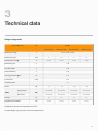
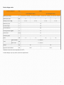
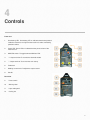
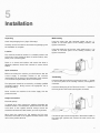
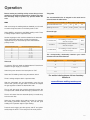
wilkinsonstar.com
Arc Series
DC MMA / LIFT TIG Welding machines
Order codes !JA-140, JA-160, JA-180, JA-200
! ! ! ! JA-160DV, JA-180DV - Dual voltage
OPERATOR MANUAL
Your new product
Thank you for selecting this Jasic Technology, Wilkinson Star product.
This product manual has been designed to ensure that you get the most from your new product. Please ensure that you are fully
conversant with the information provided paying particular attention to the safety precautions. The information will help protect
yourself and others against the potential hazards that you may come across.
Please ensure that you carry out daily and periodic maintenance checks to ensure years of reliable and trouble free operation.
Wilkinson Star Limited are a leading supplier of equipment in the UK and our products are supported by our extensive service
network. Call your distributor in the unlikely event of a problem occurring. Please record below the details from your product as
these will be required for warranty purposes and to ensure you get the correct information should you require assistance or
spare parts.
Date purchased
_____________________________________________________
From where _____________________________________________________
Serial Number
_____________________________________________________
(The serial number will normally be located on the equipment data plate on the underside of the machine or on the rear panel)
Please note products are subject to continual development and may be subject to change without notice
i
1
Safety Precautions
These general safety norms cover both arc welding
machines and plasma cutting machines unless
otherwise noted.
The equipment must only be used for the purpose it was
Insulate yourself from work and ground using dry insulating
mats or covers big enough to prevent any physical contact
with the work ground.
Never touch the electrode if you are in contact with the work
ground, or another electrode from a different machine.
designed for. Using it in any other way could result in
damage or injury and in breach of the safety rules.
Only suitably trained and competent persons should use the
equipment. Operators should
respect the safety of other
persons.
Prevention against electric shock
The equipment should be installed by a qualified person and
in accordance with current standards in operation.It is the
users responsibility to ensure that the equipment is
connected to a suitable power supply. Consult with your
utility supplier if required
If earth grounding of the work piece is required, ground it
directly with a separate cable.
Do not use the equipment with the covers removed.
Do not touch live electrical parts or parts which are
electrically charged.
Turn off all equipment when not in use.
Cables (both primary supply and welding) should be
regularly checked for damage and overheating. Do not use
worn, damaged, under sized, or poorly jointed cables.
Ensure that you wear the correct protective clothing, gloves,
head and eye protection.
Do not wrap cables over your body.
Ensure that you take additional safety precautions when you
are welding in electrically hazardous conditions such as
damp environments, wearing wet clothing, and metal
structures. Try to avoid welding in cramped or restricted
positions.
Ensure that the equipment is well maintained. Repair or
replace damaged or defective parts immediately. Carry out
any regular maintenance in accordance with the
manufacturers instructions.
Safety against fumes and welding gases
Locate the equipment in a well-ventilated position.
Keep your head out of the fumes. Do not breathe the fumes.
Ensure the welding zone is in a well-ventilated area. If this is
not possible provision should be made for suitable fume
extraction.
If ventilation is poor, wear an approved respirator.
Read and understand the Material Safety Data Sheets
(MSDS’s) and the manufacturer’s instructions for metals,
consumable, coatings, cleaners, and de-greasers.
Do not weld in locations near any de-greasing, cleaning, or
spraying operations. Be aware that heat and rays of the arc
can react with vapours to form highly toxic and irritating
gases.
2
Do not weld on coated metals, unless the coating is
removed from the weld area, the area is well ventilated, and
while wearing an air-supplied respirator. The coatings on
many metals can give off toxic fumes if welded.
Prevention against burns and radiation
Arc rays from the welding process produce intense, visible
and invisible (ultraviolet and infrared) rays that can burn eyes
and skin.
Wear an approved welding helmet fitted with a proper shade
of filter lens to protect your face and eyes when welding or
watching
Replace the coverings and protections and close all doors
when the intervention is finished, and before starting the
equipment.
Take care to avoid getting fingers trapped when loading and
feeding wire during set up and operation.
When feeding wire be careful to avoid pointing it at other
people or toward your body.
Always ensure machine covers and protective devices are in
operation.
Precautions against fire and explosion
Wear approved safety glasses with side shields under your
helmet.
Avoid causing fires due to sparks and hot waste or molten
metal
Never use broken or faulty welding helmets.
Ensure that appropriate fire safety devices are available near
the cutting / welding area.
Always ensure there are adequate protective screens or
barriers to protect others from flash, glare and sparks from
the welding area. Ensure that there are adequate warnings
that welding or cutting is taking place.
Remove all flammable and combustible materials from the
cutting / welding zone and surrounding areas
Wear suitable protective flame resistant clothing.
Do not cut/weld fuel and lubricant containers, even if empty.
These must be carefully cleaned before they can be cut/
welded.
The sparks and spatter from welding, hot work pieces, and
hot equipment can cause fires and burns
Welding on closed containers, such as tanks, drums, or
pipes, can cause them to explode.
Accidental contact of electrode to metal objects can cause
arcs, explosion, overheating, or fire.
Check and be sure the area is safe and clear of inflammable
material before carrying out any welding.
Protection against noise
Some welding and cutting operations may produce noise.
Always allow the cut/welded material to cool before touching
it or placing it in contact with combustible or flammable
material.
Do not work in atmospheres with high concentrations of
combustible fumes, flammable gases and dust.
Always check the work area half an hour after cutting to
make sure that no fires have begun.
Risks due to magnetic fields
The magnetic fields created by high currents may affect the
operation of pacemakers or electronically controlled medical
equipment.
Wear safety ear protection to protect your hearing.
Protection from moving parts
When the machine is in operation keep away from moving
parts such as motors and fans. Moving parts, such as the
fan, may cut fingers and hands and snag garments.
Wearers of vital electronic equipment should consult their
physician before beginning any arc welding, cutting, gouging
or spot welding operations.
Do not go near welding equipment with any sensitive
electronic equipment as the magnetic fields may cause
damage.
Protections and coverings may be removed for maintenance
and controls only by qualified personnel, after first
disconnecting the power supply cable.
3
RF Declaration
Equipment that complies with directive 2004/108/EC
concerning electromagnetic compatibility (EMC) and the
technical requirements of EN60974-10 is designed for use in
industrial buildings and not those for domestic use where
electricity is provided via the low voltage public distribution
system. Difficulties may arise in assuring class A
electromagnetic compatibility for systems installed in
domestic locations due to conducted and radiated
emissions.
Never allow the electrode, electrode holder or any other
electrically “hot” parts to touch a cylinder.
Keep your head and face away from the cylinder valve outlet
when opening the cylinder valve.
Always secure the cylinder safely
Never deface or alter any cylinder
In the case of electromagnetic problems, it is the
responsibility of the user to resolve the situation. It may be
necessary to shield the equipment and fit suitable filters on
the mains supply.
LF Declaration
Consult the data plate on the equipment for the power
supply requirements.
Due to the elevated absorbance of the primary current from
the power supply network, high power systems affect the
quality of power provided by the network. Consequently,
c o n n e c t i o n re s t r i c t i o n s o r m a x i m u m i m p e d a n c e
requirements permitted by the network at the public network
connection point must be applied to these systems.
In this case the installer or the user is responsible for
ensuring the equipment can be connected, consulting the
electricity provider if necessary.
Materials and their disposal
The equipment is manufactured with materials, which do not
contain any toxic or poisonous materials dangerous to the
operator.
When the equipment is scrapped, it should be dismantled
separating components according to the type of materials.
Do not dispose of the equipment with normal waste. The
European Directive 2002/96/EC on Waste Electrical and
Electronic Equipment states the electrical equipment that
has reached its end of life must be collected separately and
returned to an environmentally compatible recycling facility.
Handling of Compressed gas cylinders and
regulators
All cylinders and pressure regulators used in welding
operations should be handled with care.
4
2
Product Overview
The unique electronic structure and air channel design in
this series of machines provides efficient cooling of the
power devices as well as improving the duty cycles of the
machines. The design of the forced air-cooling system
channel can effectively prevent the power devices and
control circuits from being damaged by the dust introduced
into the machine by the fan. The reliability of the machine is
greatly improved as a result. The streamline design means
front and rear panels are naturally integrated via largeradian transition. The front and rear panels of the machine
and the handle are coated with rubber oil*, giving the
machine a very tactile and comfortable grip with an
excellent appearance.
Product functions
• Hot start arc ignition functions: ensure the arc ignition in
MMA welding easier and more reliable.
• VRD function: Provides additional safety keep the
operator safe when the machine is idle.
• Anti-sticking function: Reduces the welding current if a
short circuit occurs during welding.
• Self-adaptive arc force technology: Maintains the
optimum arc conditions during welding even with long
cables.
• Advanced scratch start arc ignition: supports TIG welding
without HF arc ignition circuit.
• Easy arc starting, less spatter, stable current and good
weld bead shaping.
• Modern high tech design
• Streamline design of front and rear panels.
• Front and rear panels made of high-intensity plastics
suitable for working in severe conditions.
• Excellent insulating property.
• Water-resistant, antistatic and anticorrosion design.
• It can be used with a wide range of welding electrodes.
Product performance characteristics
• Advanced IGBT inverter technology
• Inverting frequency of 33~43 kHz greatly reduces the size
and weight of the welder.
• Great reduction in magnetic and resistance loss enhances
the welding efficiency and energy saving effect.
• Working frequency is beyond the audio range, which
almost eliminates noise pollution.
• Industry leading control system
• Advanced control technology meets the various welding
applications and provides excellent welding performance.
• It can be used with a wide range of welding electrodes.
5
3
Technical data
Single voltage units
Technical Parameter
Unit
Model
ARC140 (JA-140)
ARC160 (JA-160)
ARC180 (JA-180)
ARC200 (JA-200)
Rated input voltage
V
Rated input power
KVA
6
7.11
8
9.4
Welding current range
A
10~140
10~160
10~180
10~200
Rated duty cycle
%
35
No-load voltage
V
63
Overall efficiency
%
85
Housing protection grade
IP
21
Cosφ
0.7
Power factor
AC230V±15% 50/60HZ
Insulation grade
F
Noise
dB
without handle
Size
<70
<70
<80
<80
313*130*206
313*130*206
313*130*206
351*130*206
313*130*250
313*130*250
313*130*250
351*130*250
mm
with handle*
Weight
Kg
4.7
4.7
4.7
5.2
Applicable electrode size
mm
1.0~4.0
1.0~4.0
1.0~5.0
1.0~5.0
Tested at the environment temperature of 400 C
Product design may vary due to customer requirements.
6
Dual voltage units
Technical Parameter
Unit
Model
ARC160DV (JA-160DV)
ARC180DV (JA-180DV)
Rated input voltage
V
AC230V±15% 50/60HZ
AC110V±15% 50/60HZ
AC230V±15% 50/60HZ
AC115V±15% 50/60HZ
Rated input power
KVA
7.11
5
8
6
Welding current range
A
10~160
10~120
10~180
10~140
Rated duty cycle
%
35
No-load voltage
V
63
Overall efficiency
%
85
Housing protection grade
IP
21
Cosφ
0.7
<80
<80
Power factor
Insulation grade
F
Noise
dB
<70
<70
without handle
Size
313*130*206
mm
with handle*
313*130*250
Weight
Kg
4.7
5.2
Applicable electrode size
mm
1.0~4.0
1.0~5.0
Tested at the environment temperature of 400 C
Product design may vary due to customer requirements.
7
4
Controls
Front view
1.
Overheating LED: Overheating LED on indicates that the temperature
inside the machine is too high and the machine is under overheating
protection status.
2.
Power LED: Power LED on indicates that the power switch of the
machine is on.
3.
MMA/TIG switch: To toggle between MMA and TIG.
4.
"+" Output terminal: To connect the electrode holder.
5.
"-" Output terminal: To connect the work clamp.
6.
Trademark
7.
Welding current knob: To adjust the output current.
8.
Handle
Rear view
9
Power switch
10
Warning label
11
Input cable gland
12
Cooling fan
8
5
Installation
Unpacking
MMA welding
Check the packaging for any signs of damage.
Insert the cable plug with electrode holder into the “+”
socket on the front panel of the welding machine, and
tighten it clockwise.
Carefully remove the machine and retain the packaging until
the installation is complete.
Location
Insert the cable plug of the work return lead into the “-”ve
socket on the front panel of the welding machine, and
tighten it clockwise
The machine should be located in a suitable position and
environment. Care should be taken to avoid moisture, dust,
steam, oil or corrosive gases
Place on a secure level surface and ensure that there is
adequate clearance around the machine to ensure natural
airflow.
Input connection
Before connecting the machine you should ensure that the
correct supply is available. Details of the machine
requirements can be found on the data plate of the machine
or in the technical parameters shown in the manual.
The equipment should be connected by a suitably qualified
competent person. Always ensure the equipment has a
proper grounding.
TIG Welding
Insert the cable plug with the work clamp into the “+” socket
on the front panel of the welding machine, and tighten it
clockwise.
Insert the cables plug of the TIG torch into the “-” socket on
the front panel of the machine and tighten clockwise.
Never connect the machine to the mains supply with the
panels removed.
Output connections
Electrode polarity
In general when using manual arc welding electrodes the
electrode holder is connected the positive terminal and the
work return to the negative terminal. Always consult the
electrode manufacturer’s data sheet if you have any doubts.
When using the machine for TIG welding the TIG torch
should be connected to the negative terminal and the work
return to the positive terminal
Connect the gas hose to the regulator / flowmeter located on
the shield gas cylinder and connect the other end to the
machine.
9
Operation
Before starting any welding activity ensure that you have
suitable eye protection and protective clothing. Also take
the necessary steps to protect any persons within the
area.
TIG guides
MMA
The welding current reference for different electrode diameter
The recommended size of tungsten to be used can be
selected from the table below
Electrode diameter /mm
After connecting the welding leads as detailed you will need
to switch the power switch on the back panel to “ON”
Select MMA by switching to the MMA welding mode. There
is voltage output at both output terminals.
Set the amperage on the machine suitable for the electrode
being used. Please see below a guide to amperages
required. Ensure you check that you have the electrode
polarity correct.
Electrode Diameter (mm)
1.0
1.6
2.0
2.5
3.2
4.0
5.0
6.0
Recommended Welding Current (A)
20~60
44~84
60~100
80~120
108~148
140~180
180~220
220~260
TIG mode
Connect the TIG torch leads as detailed above. Ensure that a
suitable inert gas supply is connected.
Switch the power switch on the back panel to “ON”
Select the TIG welding mode using the selector switch.
There is voltage output at both output terminals.
After the parameters are set appropriately, open the gas
valve of the cylinder, the gas valve on the torch and adjust
the gas regulator to obtain the desired flow rate.
Welding current /A
1.6
2.0
2.5
3.2
25-40
40-60
50-80
100-130
Electrode type
Type
Mode
Colour
Thoriated 2%
DC welding of steel, stainless
steel and copper
Red
Ceriated
DC welding of steel, stainless
steel and copper
Grey
Lanthanated
DC welding of steel, stainless
steel and copper
Black
The corresponding relationship between gas nozzle
diameter and electrode diameter
Gas nozzle diameter/mm
6.4
Electrode diameter/mm
0.5
8
1.0
9.5
1.6 or 2.4
11.1
3.2
For welder training please visit our Academy
website at
www.wilkinson-welding-academy.com
The arc will start when the tungsten electrode touches the
work piece and is lifted off after touching by between 2-4mm
The arc will cease when the electrode (torch) is moved away
from the work area
Select the spot welding time setting function by pressing
the welding parameter selecting key, and set the spot
welding time. Operation steps in spot welding:
Press the torch trigger, gas valve opens, and HF arc ignition
starts; Keep the torch 2~4mm away from the work piece to
10
6
Maintenance and troubleshooting
The following operation requires sufficient professional
knowledge on electric aspects and comprehensive
safety knowledge. Make sure the input cable of the
machine is disconnected from the electricity supply and
Troubleshooting
Before arc welding machines are dispatched from the
factory, they have already been checked thoroughly. The
machine should not be tampered with or altered.
wait for 5 minutes before removing the machine covers.
In order to guarantee that the arc welding machine works
efficiently and in safety, it must be maintained regularly.
Operators should understand the maintenance methods and
means of arc welding machine operation. This guide should
enable customers to carry on simple examination and
safeguarding by oneself, try to reduce the fault rate and
repair times of the arc welding machine, so as to lengthen
Maintenance must be carried out carefully. If any wire
becomes loose or is misplaced, it maybe potential danger to
user!
Only professional maintenance personnel should repair the
machine!
Ensure the power is disconnected before working on the
machine. Always wait 5 minutes after power switch off
before opening the case.
service life of arc welding machine
Malfunction symptom
Period
Daily
examination
Monthly
examination
Yearly
examination
Maintenance item
Carry out a full visual inspection. Check
for any damage to the machine, leads,
cables and connections. Replace where
necessary.
Switch on the machine and check for any
warning Led’s and general operation
Using the dry compressed air to clean the
inside of arc welding machine. Especially
check for build up of dust / debris on
intake grills, main voltage transformer,
inductance, IGBT module, the fast recover
diode and PCB, etc. Take care when
blowing electronic components and do not
dislodge any wiring connections
Check the security of output connections
and plugs. Replace if signs of overheating.
Carry out an annual service. Check earth
continuity and insulation resistance of the
machine at the relevant points.
PLEASE NOTE THIS WORK SHOULD
BE CARRIED OUT BY A TRAINED
COMPETENT PERSON.
Turn on the machine, the power LED
is off, the fan doesn't work, and no
Causes and Solutions
1 Check if the power switch is closed.
2 No input power.
welding output.
Turn on the machine, the fan works, 1 The current potentiometer fails. Replace
but the output current is unstable
it.
2 Check if any loose contact exists inside
and can't be controlled by
the machine. If any, reconnect.
potentiometer when welding.
1 Check if any loose contact exists inside
the machine.
2 Open circuit or loose contact occurs at the
joint of output terminal.
3 The overheating LED is on.
Turn on the machine,, the fan works, The machine is under over-heating
protection status. It can recover
but no welding output.
automatically after the welding machine is
cooled.
4 Check if the thermal switch is ok. Replace
it if damaged.
5 Check if the thermal switch is loosely
connected, and reconnect it if necessary.
The rated current of the electrode holder is
The electrode holder becomes very smaller than its actual working current.
hot.
Replace it with a higher rated current
capacity.
Excessive spatter in MMA welding.
The output polarity connection is incorrect.
Exchange the polarity.
11
7
Electrical schematic
Schematic for single voltage unit
Schematic for dual voltage unit
12
8
Parts list
Arc Pro 140 - (JA-140)
No.
Part no
1
10004957
2
Description
No.
Part no
Description
Power switch
15
10037859
Thermal Switch
10037125
Back panel
16
10037135
Driver transformer
3
10044817
Fan
17
10006282
IRF9Z24N
4
10043477
Handle
18
10006282
IRFZ24N
5
10043689
Louver
19
10037134
Switching mode power supply transformer
6
10039735
Machine Cover
20
10037345
Silicon bridge
7
10037113
Bottom panel
21
10037146
TOP266KG
8
10037128
Front panel
22
10043910
Control board
9
10044029
Quick socket
23
10037734
High frequency transformer
10
10037561
Knob
24
10005801
Electrolytic capacitor
11
10037147
LM79L15ACMX
25
10006272
Rectifying tube
12
10006431
Thermal Resistor
26
10037078
Pin insulation cover
13
10006474
Electric Relay
27
10037432
Rectifier Plate
14
10007251
IGBT
28
10037858
Power line
13
Arc Pro 160 - (JA-160DV)
No.
Part no
1
10004957
2
Description
No.
Part no
Description
Power switch
15
10037859
Thermal Switch
10037125
Back Panel
16
10037135
Drive Transformer
3
10044817
Fan
17
10006282
IRF9Z24N
4
10043477
Handle
18
10006282
IRFZ24N
5
10043689
Louver
19
10037134
Switching mode power supply transformer
6
10039735
Machine Cover
20
10037147
LM79L15ACMX
7
10037113
Bottom Panel
21
10037146
TOP266KG
8
10037485
ARC160D Silicon bridge
22
10043914
ARC160D Control Board
9
10037431
ARC160D Rectifying Board
23
10037134
ARC160D High frequency transformer
10
10006248
ARC160D Rectifier Tube
24
10038719
ARC160D Electrolytic capacitor
11
10037836
Front Panel
25
10037561
Knob
12
10006431
Thermal Resistor
26
10037078
Pin insulation cover
13
10006474
Electric Relay
27
10037152
Quick socket
14
10007251
IGBT
28
10037858
Power line
14
Arc Pro 180 - (JA-180DV)
No.
Part no
Description
No.
Part no
Description
1
10004957
Power switch
15
10037852 Thermal Switch
2
10037837
Back Panel
16
10037135 Driver transformer
3
10044009
Fan
17
10006282 IRF9Z24N
4
10043477
Handle
18
10006282 IRFZ24N
5
10043689
Louver
19
10037134
6
10037813
Machine Cover
20
10037147 LM79L15ACMX
7
10037811
Bottom panel
21
10037146 TOP266KG
8
10043405
Front Panel
22
10043912 Control Board
9
10044030
Quick Socket
23
10037735 High Frequency transformer
10
10037561
Knob
24
10038737 Electrolytic capacitor
11
10044538
Silicon Bridge board
25
10006248 Rectifier tube
12
10006431
Thermal Resistor
26
10037078 Pin insulation cover
13
10006474
Electric Relay
27
10037429 Rectifying board
14
10029693
IGBT
28
10037853 Power line
Switching mode power supply
transformer
15
Arc Pro 200 - (JA-200)
No.
Part no
1
10004957
2
Description
No.
Part no
Description
Power switch
15
10037852
Thermal Switch
10037837
Back panel
16
10037135
Drive Transformer
3
10044009
Fan
17
10006282
IRF9Z24N
4
10043477
Handle
18
10006282
IRFZ24N
5
10043689
Louver
19
10037134
Switching mode power supply transformer
6
10037813
Machine Cover
20
10037147
LM79L15ACMX
7
10037706
Bottom Panel
21
10037146
TOP266KG
8
10043405
Front Panel
22
10043912
Control Board
9
10044030
Quick Socket
23
10037735
High Frequency transformer
10
10037561
Knob
24
10005848
Electrolytic capacitor
11
10037485
Silicon bridge board
25
10006248
Rectifying tube
12
10006431
Thermal Resistor
26
10037078
Pin insulation cover
13
10006474
Electric Relay
27
10037429
Rectifier Plate
14
10029693
IGBT
28
10037853
Power line
16
17
JA Arc series DC TIG/MMA WELDING MACHINE
Order code ! JA-140, JA-160, JA-180, JA-200
! ! ! ! JA-160DV, JA-180DV - Dual voltage
© Wilkinson Star Limited
Issue 1 January 2014
Product is subject to change without notice
xviii