1
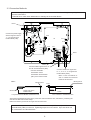
Building Air-Conditioners Control System
AIR CONDITIONER INTERFACE
Model : LMAP02-E
Installation Manual
Contents
Safety precautions ……………………………………1,2
1.Parts Inclue ……………………………………………3
2.Specifications …………………………………………3
2-1 External View ……………………………………3
2-2 Enviroment Specifications ……………………3
2-3 Connected Air Conditioning Equipment ……4
2-4 LONWORKS® Network Specifications …………4
2-5 Variables of LM-AP network …………………5
3.Installation ……………………………………………6
3-1 Locally Procured Parts …………………………6
3-2 Securing the Unit ………………………………7
3-3 Connection Methods ……………………………8
3-4 Electrical Wiring …………………………………9
4.Sysyem Settings ……………………………………10
4-1 If not used together with MELANS …………10
4-2 If used together with MELANS ………………11
4-3 Initialization Settings of LONWORKS® Network …12
5.Confirming Operation ………………………………13
5-1 Pre-operation preparations and settings ……13
5-2 Test-operation procedure ……………………13
6.Troubleshooting ……………………………………14
6-1 Abstract…………………………………………14
6-2 Troubleshooting ………………………………15
6-3 Error Code list …………………………………15
Before using the unit, please read this Installation
Manual carefully to ensure correct operation. Store this
Installation Manual in a location that is easy to find.
Echelon®,LON®,LONWORKS®,Neuron® ,3150® and the
Echelon logo are trademarks of Echelon Corporation
registered in the United States and other countries.
LonMaker™ and the Lon Users logo are trademarks of
Echelon Corporation.
Safety Precautions
• Before instralling this unit,make sure you read all the “Safety Precautions”.
• This manual describes the installation of LM-AP and wiring to the outdoor unit.
• Please look at the installation manual of an air-conditioning unit about the installation method of an air-conditioning unit.
• The “Safety Precautions” provide very important points regarding safety. Make sure you follow them.
Symbols and Terms
WARNING Statements identify condition or practices that could result in personal injury or loss of life.
CAUTION
Statements identify condition or practices that could result in damage to the unit or other
property.
• After reading this installation manual, keep it in a place where the final user can see it anytime he or she wants to it.
When someone moves, repairs or uses the LM-AP, make sure that this manual is forwarded to the final user.
Symbols used in the illustrations
: Indicates a part which must be grounded.
: Indicates that the main switch must be turned off before servicing.
(This symbol is displayed on the main unit label.) <Color: Blue>
: Beware of electric shock.(This symbol is displayed on the main unit label) <Color: Yellow>
: Please pay attention to electric shock fully because this is not Safety Extra Low-Voltage (SELV)
circuit.
And at servicing,please shut down the power supply for LM-AP.
WARNING
Ask your dealer or technical representative to install.
Any deficiency cased by your own installation may result in an
electric shock and fire.
Install in a plase which is strong enough to withstand the
weight of the unit
Any lack of the strength may cause the unit to fall down,
resulting in a personal injury.
Any deficiency caused by installation may result in an electric
shock, fire or incorrect operation.
Ensure that installation work is done correctly following
that installation manual.
Any deficiency caused by installation may result in an electric
shock or fire.
All electrical work must be performed by a licenced
technician, according to local regulations and the
instructions given in this manual.
Any lack of electric circuit or any deficiency caused by
installation may result in an electric shock or fire.
Wire and connect using the desired cables securely so
that any external force from the cable is imparted to the
terminal connections.
Imperfect connection and fixed may result in heading or fire.
Securely install the cover (panel) of the LM-AP.
If the cover (panel) is not installed properly, dust or water may
enter the unit and fire or electric shock may result.
Never modify or repair the unit by yourself.
Any deficiency caused by your modification or repair may
result in an electric shock or fire. Consult with your distributor
for repair.
Do not move and re-install the unit yourself.
Any deficiency caused by installation may result in an electric
shock or fire. Ask your distributor or special vender for moving
and installation.
Make sure that the unit is powered by dedicated line.
Other appearance connected to the same line could cause an
overload.
Make sure that there is a main power switch.
A ready accessible breaker for power source line helps
reduce the risk of electric shocks.Installation of a breaker is
mandatory in same areas.
If it is assumed that moisture advances into the unit,
such as the time of rainy weather, do not do check or
work of an electric circuit.
It may become the cause of damage of a fire and the unit by
an electric shock or corrosion.
1
CAUTION
Do not install the unit where combustible gas may leak.
If the gas leaks and accumulates around the unit, an
explosion may result.
When installing the unit in a hospital, communication
station, or similar place, provide sufficient protection
against noise.
The inverter equipment, private power generator, highfrequency medical equipment, or radio communication
equipment may cause the air conditioner to operate
erroneously, or fail to operate. On the other hand, the air
conditioner may affect such equipment by creating noise that
disturbs medical treatment or image broadcasting.
Do not use in any special environment.
Using in any place exposed to oil(including machine oil),
steam and sulfuric gas may deteriorate the performances
significantly or given damage to the component parts.
Do not wash with water.
Doing so may cause an electric shock or a malfunction.
Do not touch any PCB(Printed Circuit Board) with your
hand or tools. Do not have dust collected on the PCB.
Doing so may cause an electric shock or fire.
Do not install in any steamy place such as bath room or
kitchen.
Avoid any place where moisture is condensed into dew.
Doing so may cause an electric shock or a malfunction.
Do not install in any place where acidic or alkaline
solution or special spray are other be used.
Doing so may cause an electric shock or a malfuction.
Do not install in any place at a temperature of more then
43 ˚C or less than -15˚C.
It may become the cause of modification and failure.
Never connect the power source to the transmission line.
Doing so may caused a malfunction or a failture.
Safety dispose of the packing materials.
Tear apart and throw away plastic packaging bags so that
children will not play with them. If children play with a plastic
bag which was not torn apart, they face the risk of suffocation.
Be sure to shut off the power source of the unit and all
the other unit to connected to the unit before wiring.
Doing so may cause an electric shock or a malfunction.
Use only an earth leakage breaker and fuse of the
specified capacity.
If no earth leakage breaker is installed, it may cause an
electric shock.
Using fuse and wire or copper wire with too large capacity
may cause a malfunction of unit or fire.
Use standard wires in compliance with the current
capacity.
A failure to this may result in an electric leakage, heating or
fire.
This appliance must be earthed.
Make sure to install a protective earth(PE) line. Do not
connect the protective earth line to gas or water pipes,
lightning conductors or telephone grounding lines. Improper
grounding may cause an electric shock.
Wire so that it dose not received any tension.
Tension may caused wire breakage, heating or fire.
Do not touch the switches with wet fingers.
Touching a switch with wet fingers can cause electric shock.
A power-supply line and a transmission line do not band
together, or are not contained in the same metal pipe.
Doing so may cause a malfunction of unit.
2
1. Parts Include
Verify that the following parts are appended to the product.
Main Unit
Name
Binding band
Installation manual
Shape
Quantity
1
3
1
· The external interface file (XIF) is necessary for the product.
Upon verifying the 16-digit program ID (PID) which is bonded on the board, please contact your dealer.
2. Specifications
2-1 External View
A
59.6
360
240
9.6
60
TB1
325
340
Power supply terminal
( ~ 200 - 240V)
Detail of A
4.5
7.5
R
ø1
10
0
TB2
2-ø4.5 hole
TB21
M-NET transmission terminal
LONWORKS® transmission terminal
2-2 Environment Specifications
Item
Description
340 (H) x 360 (W) x 59.6 (D) mm
Dimensions
Net Weight
3.3 kg
Power Source
~ 220 - 240V (50/60 Hz)
Current Consumption
Operation
Environment
Temperature
50 mA (Maximum)
-15 to 43˚C
Operating Range
-20 to 60˚C
Storage Range
30 to 95 RH (No condensation)
In the control box
Humidity
Installation Environment
3
2-3 Connected Air Conditioning Equipment
Item
Description
Connected Equipment
MITSUBISHI ELECTRIC
Multiple split type air conditioners CITY MULTI
Split-type air conditioners
Mr.SLIM
Heat recovery ventilators
LOSSNAY
(* For details of the connected models, please contact the dealer.)
Number of Units
LM-AP can control 50 indoor units (including LOSSNAY)
2-4 LONWORKS® Network Specifications
Item
Description
Neuron CHIP
TMPN3150 (10MHz)
Network Transceiver
FTT-10A (Free Topology 78kbps)
Average communication capacity
2.5 inputs/second
Peak communication capacity
50 inputs/second (for one second)
Performance
* The proper communication is not obtainable when communication intervals exceed its performance,
assure sufficeint intervals.
* ACK Service is recommended for the network service.
* Detailed specifications for the LONWORKS® network can be found in “ FTT-10A Free Topology Transceiver
User's Guide ” by Echelon Corporation.
4
2-5 Variables of LM-AP network
The following are applied to the CITY-MULTI type indoor unit of the Multiple split type air conditioners CITY MULTI.
If Mr.SLIM or LOSSNAY is used, refer to the technical guide for the details of the network variables.
Network Variables
Request On/Off
nv1n nviOnOff_n
nv2n
nvoOnOff_n
On/Off run state
Request Mode
nv3n nviMode_n
nv4n
nvoMode_n
Mode state
Setpoint from network
(Both cool and heat)
nv5n nviSetPoint_n
nv6n
nvoSetPoint_n
Setpoint state
(both cool and heat)
Request Fanspeed
nv7n nviFanSpeed_n
nv8n
nvoFanSpeed_n
FanSpeed state
nv10n nvoThermo_n
Thermo On/Off state
nv12n nvoSpaceTemp_n
Temperature state
of indoor
nv16n nvoAlarm_n
Alarm state
Request Local
(note3,4) Prohibit On/Off
nv19n nviProOnOff_n
nv20n nvoProOnOff_n
Local Prohibit (note3)
On/Off state
Request Local
(note3,4) Prohibit mode
nv21n nviProMode_n
nv22n nviProMode_n
Local Prohibit (note3)
mode state
Request Local
(note3,4) Prohibit SetPoint
nv23n nviProSetPoint_n
nv24n nviProSetPoint_n
Local Prohibit
SetPoint state (note3)
(note1) The case of CITY MULTI is indicated.
(note2) There is a case which cannot be used with the system configuration of the air conditioners units.
(note3) “n” of the network variable shows indoor unit address (M-NET).
(note4) It is possible to use when the “MA” remote controler.
Fanction
Item
Request On/Off
Request Mode
Setpoint from network(Both cool and heat)
Operation Request Fanspeed
Request Local Prohibit On/Off
Request Local Prohibit mode
Request Local Prohibit SetPoint
Request All Off
On/Off run state
Mode state
Setpoint state(both cool and heat)
FanSpeed state
Thermo
On/Off state
Monitor
Temperature state of indoor
Alarm state
Local Prohibit On/Off state
Local Prohibit mode state
Local Prohibit SetPoint state
5
3. Installation
<Notes>
Read and understand the contents of Chapter 1 “Safety Precautions ” before performing the installation.
3-1 Locally Procured Parts
Prepare the following prior to installing the unit.
Locally procured parts
Contents
Power wire
and ground wire
Use the sheathed vinyl cord or wire.
Wire type ……… Waie is not lighter than light poly vinyl
<hloride sheathed flexible cord according to IEC 227
(designation H03 VV-F or H03 VVH2-F)>
Wire size ……… 0.75mm2 to 1.25mm
M-NET
transmission wire
Use the sheathed vinyl cord or wire.
Wire type ……… CREVS, CVVS or equivalent"
Wire size ……… Solid wire : ø1.2mm to ø1.6mm
Twist type : 1.25mm2 to 2mm2
LONWORKS® Network
transmission wire
Use the wire which is recommended by Echelon Corporation.
For details, refer to “FTT-10A Free Topology Transceiver User's Guide”.
For reference, Cable Types and Txpical Parameters.
Wire
dia /AWG
Rloop
Ω/km
C
nF/km
Vprop
% of C
Belden 85102, single twisted pair,
standed 19/29, unshielded, 150˚C
1.3mm/16
28
56
62
Belden 8471, single twisted pair,
standed 19/29, unshielded, 60˚C
1.3mm/16
28
72
55
Level IV 22AWG, twisted pair,
typically solid & unshielded
0.65mm/22
106
49
67
JY(St) Y 2X2X0.8, 4-wire herical twist,
solid, shielded
0.8mm/20.4
73
98
41
TIA568A category 5 24AWG, twisted pair 0.51mm/24
168
46
58
Cable type
If a shielded cable is used, the shield should be connected to earth ground via a single 470kΩ,
1/4 Ωatt, ≤10%, metal film resistor to prevent static charge build-up.
Screw
To install the main body, prepare four M4 screws which are suitable for the installation area.
Switch
Switch
Capacity
3A
Breaker for wiring
Breaker for Current Leakage
3A
3A 30mA
0.1 sec or less
Fuse
3A
Use a breaker with a contact distance of 3mm or more.
6
3-2 Securing the Unit
• When installing the product, assure a space enough to install and remove the cover of the main body.
• Use M4 screws as shown in Fig. below to fix the product.
To prevent the product from dropping, make sure to fix four places.
20
Installation space
20
20
20
CAUTION
• This unit does not have a water-resistant design. Always install the unit indoors or
inside a control panel.
• Install in an area capable of withstanding a 3.3 kg load.
7
3-3 Connection Methods
Use wire clamps provided to secure the wires and prevent external force from being conveyed by the wire to
the wire connections.
* External force could cause deformation or damage to the terminal blocks.
Note1
R S
UP
Connect the power supply
wires and ground wire to
“L”, “N” and ground of
terminal block (TB1).
CN605
L.B.
CNL12
CN33 CN31
CN71
CN702
P.B.
TB21
CN405
CN21
CN32
CNS3
CN45
CN65
1
LON TB21
2 3 4
A B S
Note1
Note1
Connect M-NET signal wire to “A”
and “B” of terminal block (TB2).
• Connect the M-NET
transmission wire to
transmission terminal block
(TB7) of the central control.
Note1
Connect LONWORKS® signal wire
to “1”, “2” or “3”, “4” of signal wire
terminal block (TB21).
• TB21-“1” and “3” as well as “2”
and “4” of TB21 are connected
inside the circuit board.
Binding band
Binding band
8mm
Ground wire
20mm
Power wire 35mm
M-NET 20mm
80mm
For LONWORKS® transmission wire
For power wire and M-NET transmission wire
Attach the appended binding band to the power wire and transmission wire, and fasten it, positioning the
area at inner side than the wire clamp.
Make sure that the ground wire is longer than the other wires.
Use a small screwdriver to connect diameter 0.2 to 2.5 mm2 (AWG24 to 12) cable for
terminal block (TB21) on the unit. Tightening torque is 0.5 to 0.6 Nm. Up to two wires can
be connected to one terminal block.
8
3-4 Electrical Wiring
TB1
T2
1
3
5
7
CN71
F
AC250V
2A F
Unit Body
1
2
P.B.
CN21
ZNR1
1
3
CN32
CN40
8
7
ON
OFF
1
10
1
6
SW3
ON
OFF
1
6
LED009
(WDT)
LED201
(18007RST)
CN41
CNL12
1
2
3
4
LED502
(3150RST)
LEDL
(Service
LED)
1
2
3
4
SWL
(Service
Switch)
1
3
CN65
ON
OFF
M-NET
Power Supply
DSA1
CN45
8
5 6
ZNR2
4
T1
SW2
SW1
L.B.
CN605
5 6
1
2
3
4
5
6
3
1 3 CN31
2
1 3 CN33
SWU1
(1st digit)
SWU2
(2nd digit)
SW4
0 1
9
3
LED001 LED003
LED002 LED004
Unit Body
Power supply
220-240V~/N 50/60Hz
0 1
7
9
(Wink)
2
L
N
PE
4
Breaker 3A
1
2
3
4
5
6
SW71
(Termination Switch)
ON
OFF
12
LED402
(5VM)
CN405
CNS3
3
12
1
CN702
TB21
1
2
Unit Body
1234
Unit Body
TB2
ABS
LONWORKS® transmission line
TO M-NET transmission line
(Centralized control line)
SYMBOL EXPLANATION
SYMBOL
L.B
P.B
F
T1.2
SW1, 2, 3
SW71
SWU1, 2
SWL
SYMBOL
LED001 ˜ 004
NAME
LM-AP main board
Power circuit board
Fuse AC250V 2A F
Transformer
Switch
Function selection
Tremination selection switch
(LONWORKS® )
M-NET address switch
Service switch (LONWORKS® )
NAME
Maintenance LED
Use LED001 as Wink
(LONWORKS® ) at SW2-1 ˜ 6 OFF
Status LED
Service LED (LONWORKS® )
Terminal Power source
block
M-NET transmission line
LONWORKS® transmission line
Power Supply switch connector
Earth terminal
LED
LED009/201/502/402
LEDL
TB1
TB2
TB21
CN40/CN41
Explanation of function switch
SW
Switch name
SW1-1 Function switch
of local prohibit
ON
OFF
ON
SW1-2 Used together
with MELANS switch OFF
SW1-3 Indoor temperature ON
state interval switch
SW1-5 Function switch
of LOSSNAY
SW1-6 Function switch
of Mr.SLIM
SW1-9 Indoor units
test run switch
SW3-2 Initialization
switch of the air
conditioners units
Factory
Set timing
setting
OFF Before turning
Operation local prohibit nv inputfrom
local prohibit effective
on the power supply
LONWORKS® becomes Effective when switch ON.
Operation local prohibit nv input from
local prohibit invalidity
LONWORKS® becomes invalid when switch OFF.
used together with MELNAS
OFF Before turning
on the power supply
not used together with MELNAS
OFF Before turning
Transmission interval
*number of indoor unit should
on the power supply
(1minutes or more)
be connected 30 or less
Function
Note
OFF Transmission interval
(10 minutes or more)
ON LOSSNAY is operation
from LONWORKS®
OFF LOSSNAY interlocks
with the indoor unit
ON Mr.SLIM is operation
from LONWORKS®
OFF Mr.SLIM is not operation
from LONWORKS®
ON ON(test run) is transmitted
to the indoor units
OFF OFF is transmitted to the
indoor units
ON Connected cancellation
command is transmitted
to the indoor units
OFF None
Please turn on the switch when LOSSNAY
is operation from LONWORKS®.
Please turn off the switch when LOSSNAY
interlocks with the indoor units.
Please turn on the switch when Mr.SLIM
is operation from LONWORKS®.
9
OFF
Before turning
on the power supply
OFF
Before turning
on the power supply
OFF
Always
OFF
Always
4. System Settings
This chapter only addresses the system settings of this product.
For the installation work and electrical work, refer to the last chapter “ 3. Installation ”.
<Notes>
Read and understand the contents of Chapter 1 “Safety Precautions ” before performing the installation.
The system setting is different depending on the system configuration connected.
Check the system configuration.
1. When the system controller is not used together.
2. When the system controller is used together.
Note: Function switch setting of LM-AP is different according to the management item of the equipment
connected with LONWORKS® . Carefully set the system.
4-1 If not used together with MELANS.
Switch the short-circuit connector
from CN41 to CN40.LM-AP
❇ OC : Outdoor Unit
: Switch Position
as is
OC
LM-AP
CN41
CN40
SW2-1 [OFF]
M-NET transmission line
(Centralized control line)
TB2
CN41
ON
OFF
1 2 3 4 5 6 7 8 9 10
E
TB7
M-NET transmission line
(Indoor/outdoortransmission line)
TB3
Shielded line ground
as is
SW1-2 [OFF]
OC
ON
SW2-1 [OFF]
OFF
1 2 3 4 5 6 7 8 9 10
CN41
ON
OFF
M-NET address 201 to 250 [factory setting 247]
(* Setting of position 100 not required.)
1 2 3 4 5 6 7 8 9 10
TB7
Iteam
TB3
M-NET transmission line
(Indoor/outdoortransmission line)
Setting
Factory setting
247
M-NET address of LM-AP
SWU2, 1 [201 to 250]
LM-AP power switch connector
CN41 to CN40 (supplies power)
CN41
Combined switch for LM-AP system controller
SW1 - 2 [OFF] (Not used together with MELANS)
OFF
OC central control (SC) on/off switch
SW2 -1 [OFF] (No central control)
OFF
OC power supply connector
CN41 as is (power not supplied)
CN41
(Note:1)When connecting LOSSNAY, settings must be made in the LM-AP.
1) Do not sequence LOSSNAY to the air conditioner. (Independent LOSSNAY)
Or when operation is to be controlled from LONWORKS® (BMS etc.) connectedto the LOSSNAY remote control.
LOSSNAY selection switch. (SW1-5)[ON]
2) When sequencing LOSSNAY to the air conditioner (sequenced LOSSNAY), and not controlling operation
from an LONWORKS®. (BMS etc.)
LOSSNAY selection switch. (SW1-5)[OFF]
When sequencing LOSSNAY to the air conditioner, the indoor unit and LOSSNAY sequence must be
registered from the remote control.(Refer to the remote control installation manual for details on registering.)
(Note 2)When changing the system configuration, such as the M-NET address, always carry out the following steps.
Always turn the power OFF before changing the LM-AP settings.
1) Make changes to change the unit system.(Addition of indoor unit, change of M-NET address, change of group, etc.)
2) Turn the LM-AP service switch (SW2-1) [ON].
Change the LM-AP system information delete switch (SW3-2) from [OFF] to [ON].
3) When erasing the system information, the maintenance LED “System Information Erase LED (LED001)” will turn ON.
4) When the system information has been erased, the maintenance LED “System Information Erase LED (LED001)”
will turn OFF, and the maintenance LED “System Information Erase Complete LED (LED002)” will turn ON.
5) Turn the LM-AP service switch (SW2-1) [OFF].
Change the LM-AP system information delete switch (SW3-2) from [ON] to [OFF].
Turn the LM-AP power OFF.
7) To change the LM-AP M-NET address and settings, carry out the changing work.
8) Turn the LM-AP power ON.
(Note 3) Refer to the “System Design and Construction Manual” for the outdoor unit for details on the M-NET wiring length.
(Note 4) Set the M-NET address so that it is not duplicated with other units.
10
4-2 If used together with MELANS.
Power supply unit
E
Shielded wire ground
❇ OC : Outdoor Unit
: Switch Position
Centralized controller
(MELANS)
as is
as is
OC
LM-AP
SW2-1 [OFF]
M-NET transmission line
(Centralized control line)
TB2
CN41
ON
CN41
OFF
1 2 3 4 5 6 7 8 9 10
TB7
SW1-2 [ON]
TB3
M-NET transmission line
(Indoor/outdoortransmission line)
ON
OFF
as is
1 2 3 4 5 6 7 8 9 10
OC
SW2-1 [ON]
CN41
ON
OFF
M-NET address 201 to 250 [factory setting 247]
(* Setting of position 100 not required.)
1 2 3 4 5 6 7 8 9 10
TB7
TB3
M-NET transmission line
(Indoor/outdoortransmission line)
Item
Setting
Factory setting
247
M-NET address of LM-AP
SWU2, 1 [201 to 250]
LM-AP power switch connector
CN411 as is (power not supplied)
CN41
Combined switch for LM-AP MALANS
SW1 - 2 [ON] (Used together with MELANS)
OFF
OC central control (SC) on/off switch
SW2 -1 [ON] (Central control)
OFF
OC power supply connector
CN41 as is (power not supplied)
CN41
(Note:1) When connecting LOSSNAY, register the sequence must be registered from the shared MELANS.
(Note 2) When changing the system configuration, such as the M-NET address, MELANS being shared must be
registered or changed.
(Note 3) Refer to the “System Design and Construction Manual” for the outdoor unit for details on the M-NET wiring length.
(Note 4) Set the M-NET address so that it is not duplicated with other units.
11
4-3 Initialization Settings of LONWORKS® Network
(1) Termination of LONWORKS®
The product can be set with the termination of LONWORKS® .
Termination Switch (SW71)
SW71-1
OFF
ON
OFF
ON
SW71-2
OFF
OFF
ON
ON
Termination Resistance Value
– ( Factory setting)
100Ω ± 1%
50Ω ± 1%
For details, refer to “ FTT-10A Free Topology Transceiver User's Guide ” of Echelon Corporation.
For reference, the system specifications and Transmission specifications are described.
(2) System Specifications
• Up to 64 FTT-10/FTT-10A transceivers are allowed per network segment.
• LPT-10 transceivers may be used on network segments with FTT-10/FTT-10A transceivers, but are
subject to additional constraints, particularly on distance.
See the LPT-10 Use's Guide for more information.
• The average temperature of the wire must not exceed +55˚C, although individual segments of wire may
be as hot as +85˚C.
(3) Transmission Specifications
Doubly-Terminated Bus Topology Specifications
Maximum bus length
Belden 85102
2700
Belden 8471
2700
Level IV 22AWG
1400
JY(St)Y 2X2X0.8
900
TIA Category 5
900
Units
meters
Free Topology Specifications
Maximum node-to-node distance
Maximum total wire length
Belden 85102
500
500
Belden 8471
400
500
Level IV 22AWG
400
500
JY(St)Y 2X2X0.8
320
500
TIA Category 5
250
450
Units
meters
The free topology transmission specification includes two components which must both be met for proper
system operation. The distance from each transceiver to all other transceiver and to the termination
(including the LPI-10 termination, if used) must not exceed maximum node-to-node distance.
If multiple paths exist, e.g., a loop topology, then the longest path should be used for the calculations.
The maximum total wire length is the total amount of wire connected per segment.
12
5. Confirming Operation
5-1 Pre-operation preparations and settings
(1) Perform the previous operations described in Chapter 3 “ Installation” , Chapter 4 “ System Settings” .
(2) Perform a test operation of indoor units. If being used together with MELANS, perform the installation and electrical
installation for MELANS.
(3) Turn on the power supply for LM-AP. If being used together with MELANS, perform the initialization settings.
(4) The units will be idle until the LM-AP initialization has been completed (LED002 goes out).
❇ This requires approximately 5 to 10 minutes. (If being used together with MELANS, it will be approximately
3 minutes after the completion of the initialization settings.)
(5) Check whether or not LM-AP service LED (LED003 and LED004) have come on.
(6) Refer to the following chapter “6. Troubleshooting” if the LM-AP connection error (LED003) or unit error (LED004) is ON.
(Note 1) Always refer to the previous chapter “4. System settings” before changing the system configuration,
such as the M-NET address.
❇ After confirming the above details, always refer to the following section “5-2. Trial operation procedures” and
make confirmations with trial operations.
❇ Turn all of the switches in the service switch (SW2) [OFF] to confirm the ON/OFF status of the above service LED
(LED002, LED003 and LED004).
5-2 Test-operation procedure
(1) Test-operation of the indoor unit from LM-AP
1. Turn on SW1-9 of LM-AP.
❇ If there is even one indoor unit that is not running, the LM-AP may not correctly recognize the indoor unit.
Refer to the next chapter “Troubleshooting”.
2. Finally turn OFF SW1-9, and verify that all indoor units are stopped.
(2) Test-operation of the indoor unit from LONWORKS®
If there is any tool which corresponds to LONWORKS®, verify that it can be operated from LONWORKS® network according
to the following procedure.
1. Set the LM-AP in the config.
If LM-AP has been already bounded to another model (the service LED is not ON), don't apply any new binding.
2. During the test operation, use “ nv1n Reguest On/Off ” to verify that the indoor unit can be operated.
For details of “ nv1n Reguest On/Off ” , refer to the following.
nv1n Reguest On/Off
network input SNVT_switch nviOnOff_n ;
This input network variable is used to allow On reguest or Off reguest of the indoor unit to be changed via
the network.
When the ventilator(LOSSNAY) interlocks with the inddor unit, it becomes the same operations the indoor uint.
Valid Range
value field
state field
state field
: not used
:0
= Indoor unit or ventilation unit is Off.
:1
= Indoor unit or ventilation unit is On.
: Else = Indoor unit or ventilation unit is Off.
_n … Indoor unit address (M-NET)
3. Finally put the LM-AP in the unconfig, and end the test operation.
Contact your dealer for details on trial operation from the LONWORKS® network.
13
6. Troubleshooting
6-1 Abstract
If LM-AP does not properly operate, first check the following contents.
Item
Normal state
Contents to check
LED009
ON
Check for turn-off on the power supply (TB1) of LM-AP,
disconnection on the connectors (CN605, CN65, CN32, CN33, CN31, CN71)
and blown fuse (F).
LED402
ON
Check for turn-off on the power supply (TB1) of LM-AP,
disconnection on the connectors (CN405, CN45, CN21, CN31, CN71)
and blown fuse (F).
Service LED
—
It blinks when it is not binding.
At this time, operation is unavailable from the network side from LONWORKS®.
Binding the equipment which corresponds to LONWORKS® network.
LED002
OFF
If it is ON when the dip switch SW2 is all OFF, the LM-AP is incompletely initialized.
Wait for 15 minutes after the power supply is turned on (Until the initializing process
is completed).
LED003
OFF
If it is ON when the dip switch SW2 is all off, check the setting of the switches and
so on, and turn on the power supply again.
LED004
OFF
If it is ON when the dip switch SW2 is all off, the indoor unit may be troubled.
Check the connection and setting of all indoor units.
CN40/41
—
If the power supply unit is connected, insert the jumper connector to CN41.
If the power supply unit is not connected, insert the jumper connector to CN40.
SW71
—
LONWORKS® The switch sets the termination of LONWORKS® network.
According to the system design of LONWORKS® network, check whether it is properly
set or not.
M—NET
Address switch
SWU1, SWU2
—
Dip switch
SW1, SW2,
SW3
—
If MELANS is used, check whether M-NET address is overlapped or not.
Initial setting of LM-AP is 247.
Check whether MELANS is present or not (SW1-2), and whether the
independent/combined LOSSNAY (SW1-5) is properly set or not.
Moreover, verify that all other switches are all off.
14
6-2 Troubleshooting
No.
Error content
1
Even if it is in testoperation with
LM-AP, the air
conditioner does
not run.
2
3
4
Even if the
operation is tested
on LM-AP, the
LOSSNAY does
not operate.
Cause
Checking method and remedy
(1)The LM-AP is not completely
initialized.
Turn off all SW2. After verifying that LED002 is OFF,
test the operation again.
(2)Setting on M-NET side is not properly
completed.
Verify that the test operation of the air conditioner is
properly completed. Verify that M-NET transmission
line is properly connected.
(3)If MELANS is used together LM-AP is
not registered to MELANS.
In MELANS, register LM-AP as the sub MELANS.
(1)The LM-AP is not completely
initialized.
Refer to 1-(1).
(2)Setting on M-NET side is not properly
completed.
Refer to 1-(2).
(3)If MELANS is used in combination,
LM-AP is not registered to MELANS.
Refer to 1-(3).
(4)The independent/combined
LOSSNAY of LM-AP is not set.
Turn on SW1-5 of LM-AP, and reset the power supply.
Even if it is operated (1)The LM-AP is not completely
initialized.
with the remote
controller/MELANS,
it is not informed to (2)Setting on M-NET side is not properly
completed.
the host on LON
side.
(3)If MELANS is used in combination,
LM-AP is not registered to MELANS.
LM-AP is not
completely
initialized.
Refer to 1-(1).
Refer to 1-(2).
Refer to 1-(3).
(4)LONWORKS® network transmission
line is not properly connected.
Check for disconnection on TB21, short-circuit and
wire breakage on the network wire and so on.
(5)The termination of LONWORKS®
network is not properly set.
Verify that the termination of LONWORKS® network is
properly set according to the system design.
(6) Binding of LONWORKS® network is
not properly ended.
Apply the binding again.
(1)Much time is necessary until the
initialization is completed. (Normal
state)
In some case, it takes approx. 15 minutes until the
initialization process is ended.Wait until the
initialization is ended.
15
Error content
5
6
Independent/combi
ned LOSSNAY can
not be operated
from the LON side.
Air conditioner can
not be operated
from the LON side.
Cause
Checking method and remedy
(1)The LM-AP is not completely
initialized.
Refer to 1-(1).
(2)Setting on M-NET side is not properly
completed.
Refer to 1-(2).
(3)If MELANS is used together LM-AP is
not registered to MELANS.
Refer to 1-(3).
(4)The independent/combined
LOSSNAY of LM-AP is not set.
Refer to 2-(4).
(4)LONWORKS® network transmission
wire is not properly connected.
Refer to 4-(4).
(5)The termination of LONWORKS®
network is not properly set.
Refer to 4-(5).
(6) Binding of LONWORKS® network is
not properly ended.
Refer to 4-(6).
(1)The LM-AP is not completely
initialized.
Refer to 1-(1).
(2)Setting on M-NET side is not properly
completed.
Refer to 1-(2).
(3)If MELANS is used together LM-AP is
not registered to MELANS.
Refer to 1-(3).
(4)LONWORKS® network transmission
wire is not properly connected.
Refer to 4-(4).
(5)The termination of LONWORKS®
network is not properly set.
Refer to 4-(5).
(6) Binding of LONWORKS® network is
not properly ended.
Refer to 4-(6).
16
6-3 Error code list
Error
code
Error content
Symptom
Cause
Countermeasure
6600
M-NET duplex
error
• If it has been confirmed that
a unit with the same M-NET
address is transmitting.
• If there is two or more units with the
same M-NET address at the unit and
controller.
• Check that there are no
duplicate addresses.
After correcting
problem, reset power
supply.
6601
M-NET polarity
not set error
• When discrimination of the
polarity of the M-NET
transmission wire.
• Interrupted power supply, Connectors
(CN405, CN45, CN21, CN71).
Damage to transformer (T2).
• Interrupted power supply for M-NET
transmission wire.
• Check for defects. Once
corrected, reset the
power supply.
6607
No ACK error
• If there is no response
(ACK) from the recipient
after a transmission.
• If recipient of transmission is LM-AP.
• Check these areas.
• Defect in transmission line
After correcting
(TB2)between LM-AP.
problem, reset power
• Interrupted power LM-AP power
supply.
supply (TB1).
• Blown fuse (F1) in LM-AP
disconnection on the loose connector
(CN605, CN65, CN32, CN33, CN31).
• Damage transformer in LM-AP(T1, T2).
Damage circuit board (L.B, P.B).
17
This product is designed and intended for use in the residential,
commercial and light-industrial environment.
The product at hand is based on
the following EU regulations:
Low Voltage Directive 78/23/EEC
• Electromagnetic Compatibility Directive
89/336/EEC
•
HEAD OFFICE MITSUBISHI DENKI BLDG.MARUNOUCHI TOKYO 100-0005 TELEX J24532 CABLE MELCO TOKYO
WT03223X02