1
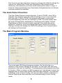
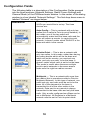
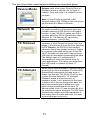
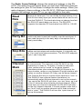
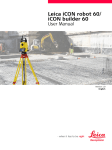
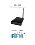
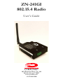
ZN-241GI
802.15.4 Radio
User’s Guide
3079 Premiere Pkwy, Ste. 140
Duluth, Georgia 30097
www.cirronet.com
+1 678 684-2000
Important Regulatory Information
Cirronet Product FCC ID: HSW-ZN241
IC 4492A-ZN241
Note: This unit has been tested and found to comply with the limits for a Class A
digital device, pursuant to part 15 of the FCC Rules. These limits are designed to
provide reasonable protection against harmful interference when the equipment is
operated in a commercial environment. This equipment generates, uses, and can
radiate radio frequency energy and, if not installed and used in accordance with the
instruction manual, may cause harmful interference to radio communications.
Operation of this equipment in a residential area is likely to cause harmful interference
in which case the user will be required to correct the interference at their expense.
FCC s MPE Requirements
Information to user/installer regarding FCC s Maximum Permissible
Exposure (MPE) limits.
Notice to users/installers using the following mobile antennas, with Cirronet RF products:
ZN241 5 dBi and 2 dBi Omni Antennas
The field strength radiated by any one of these antennas, when connected to Cirronet RF
products, may exceed FCC mandated RF exposure limits. FCC rules require professional
installation of these antennas in such a way that the general public will not be closer than
20 cm from the radiating aperture of any of these antennas. End users of these systems
must also be informed that RF exposure limits may be exceeded if personnel come closer
than 20 cm to the apertures of any of these antennas.
Declaration of Conformity
The ZN241G to which this declaration relates is in conformity with the essential
requirements of the R&TTE directive 1999/5/EC and complies with the following
standards and/or other normative documents:
For Interfaces
EN 55022
EN 55024
For RLAN Transceiver
EN 300 328
EN 301 489 -1, -17
EN 60950
Use Within the European Union
The ZN241G is intended for use within the European Community States.
When used with a 2 dBi antenna the power output must be set to 10 dBm.
When used with a 9 dBi antenna the power output must be set to 3 dBm.
Getting Started
The ZN-241G Starter Kit contains all of the items listed below. Before
starting, identify each of the items in your kit.
o
o
o
o
o
o
o
ZN-241GI Radio Unit
Reverse polarity antenna
Loop-Back Jumper
Wall-mount power supply
RS-232 Configuration Cable
Additional Data/Power Supply connector
Software and Manual CD
The ZN-241GI radio is a simple-to-use, simple-to-setup wireless
networking device. With its Auto-Config mode, all that is needed to send
data between two ZN-241GIs is to attach the antennas, connect the
radios to serial ports and plug in the power supplies. Each step is
described below.
The ZN-241GI supports both three-wire RS-232 and two-wire RS-485
communications. The default mode is three-wire (RX, TX and GND) RS232. To select two-wire RS-485 you must connect the 485_EN pin on the
Data/Power Connector to ground. Note that the pin adjacent to the
485_EN pin on the Data/Power Connector is ground.
Note that a ZN-241GI can link with another ZN-241GI, ZN-241G or ZN241GU. The radios in all of the ZN-241G models are the same, it is only
the serial interface that is different.
This manual will walk you through getting two ZN-241Gs to run a
communications test and then describe some of the optional settings
available to you. The test requires that you have a second ZN-241G.
Identifying Indicators
The green Power LED is illuminated when adequate power is supplied to
the unit. The red Link LED comes on when the ZN-241GI has linked with
another ZN-241G. The yellow Data LED flashes on and off when data is
transmitted or received by the ZN-241GI.
1
Attaching the Antenna
The ZN-241GI radio is supplied with a foldable antenna with a screw
type connector. Attach the antenna to the ZN-241GI by threading the
antenna onto the antenna connector on the rear of the ZN-241GI, turning
until finger tight. Fold the antenna at a right angle so the antenna is
sticking up above the ZN-241GI.
If the folding part of the antenna is not in the right position to stick up
above the ZN-241GI, hold onto the knurled bottom of the antenna and
twist the upper part of the antenna until the foldable part of the antenna
sticks up above the ZN-241GI. DO NOT TWIST THE ENTIRE ANTENNA
AS THIS MAY DAMAGE THE ANTENNA.
Using the Data/Power Connector
The Data/Power connector is designed to allow easy installation and
removal of individual wires. All needed wires should be installed in the
connector before plugging the connector into the ZN-241GI. Once
installed, the connector can be removed and reinstalled as needed;
however, do not pull on the wires to remove the connector as this may
cause the connections to fail.
The Data/Power connector can accept individual wires ranging from 26
to 20 gauge in size. To connect a wire, position the connector such that
the holes for the wires are along the top and the small orange levers are
along the bottom. Strip the insulation from the wire to be connected to
expose about ¼” of bare conductor. Locate the orange lever beneath the
hole you want to use for the wire. Using a small screwdriver or nail file,
depress the orange lever and insert the wire into the hole. The wire
should easily slide into the hole. Once the wire is fully inserted, release
the orange lever. This will allow the springs inside the connector to
securely connect the wire.
2
Installing the Loop-Back Jumper
To run the communications test, it is necessary to install the Loop-Back
jumper between pins 5 and 6 on one of the ZN-241GIs. This will send
whatever data is transmitted to the ZN-241GI back to the ZN-241G that
sent the data. This removes the need to have two PCs to run the test.
The Loop-Back connector is just a short piece of wire. Depress the two
orange levers below the Data/Power holes corresponding to pins 5 and 6
on the ZN-241GI. When the holes for the wires are along the top, pin 1
will be on the left looking at the orange levers. Pins 5 and 6 are the last
two pins on the right side of the connector. Once the Loop-Back jumper
is inserted, release the two orange levers to secure the connection.
RS-232C Operation
The ZN-241GI is shipped from the factory set up for three-wire RS-232C
operation. Three-wire means a device can communicate with the ZN241GI with just Tx, Rx, and Ground connected. Three-wire also means
there is no flow control. Thus the device attached to the ZN-24GI must
be able to receive all the data the ZN-241GI sends to it and the device
must not send data to the ZN-241GI faster than it can be transmitted.
The ZN-241GI was designed to operate in polling environments and can
handle data packets up to 75 bytes in length.
The Tx signal on the ZN-241GI is an output and should be connected to
the RX input of the connected device. The Rx signal on the ZN-241G is
an input and should be connected to the Tx output of the connected
device.
RS-485 Operation
By connecting pins 3 and 4 on the Data/Power connector of the ZN241GI, two-wire RS-485 operation is selected. (After the communications
test, the Loop-Back jumper can be used to select 485 mode if desired.)
Two-wire operation means that the ZN-241GI can either be outputting
data on the 485 lines or receiving data on the 485 but not both
simultaneously. This is also called half-duplex operation. This mode of
operation is typically used in polling environments, such as Modbus.
Some master device in the network must insure that only one device is
sending data at any given time. This is what happens naturally in a
polling environment.
Baud Rates
The default baud rate for the ZN-241GI is 38,400 bps in both RS-232C
and RS-485 modes of operation. The ZNWizard program can be used to
change the baud rate.
3
Connecting the ZN-241GI to a Computer
The ZN-241GI is designed to connect to the serial port of a personal
computer or an industrial device with either an RS-232C or two-wire RS485 serial port. Configuration of the ZN-241GI is performed using the
ZNWizard program running on a PC. To connect to a PC, use the
Configuration Cable provided, connect one end to a serial port on your
computer and the other end to the serial connector on the rear of the ZN241GI. Make sure that RS-232C operation is selected.
Applying Power to the ZN-241GI
Power is supplied to the ZN-241GI through the Data/Power Connector
on the rear of the unit. The ZN-241GI accepts DC power in the range of
+9V to +24V. A 9VDC wall-mount power supply is provided with the ZN241GI as part of the Configuration Cable. If the ZN-241GI will be used
with an RS-232C device, the Configuration Cable may be used.
Alternatively, an external DC supply between +9V to +24V may be used.
A second Data/Power Connector is included with the unit. The
Data/Power Connector pinout is provided in the table below.
Pin Number
Signal
1
Vcc - +9VDC to +24VDC
2
Ground
3
485_EN – Connect to Ground for 485 operation
4
Ground
5
TX/A – RS-232C Transmit Data, 485 A Signal
6
RX/B – RS-232C Receive Data, 485 B Signal
4
Connect the wall-mount end of the power supply to a wall outlet with
either 110VAC or 220VAC. The Power LED on the ZN-241GI will come
on and after a moment the Data LED will blink. The Data LED blinking
means the ZN-241GI is looking for another ZN-241G to link to.
Repeat this step with the other ZN-241GI. After a few seconds, the Link
LEDs on both ZN-241Gs will be lit. This indicates that the two ZN-241Gs
have established a wireless link.
Sending and Receiving Data
To send and receive data, a communications program is required. Most
PCs come with a communications program called Hyper Terminal. This
can be found by clicking on Start, then All Programs, then Accessories,
then Communications then Hyper Terminal. The following screen will
display.
When Hyper Terminal starts, it asks you to name the connection. Enter
ZN-241G and click OK.
Hyper Terminal will then ask you how you want to connect. Ignore the
boxes for country code and area code and click on the drop down arrow
on the bottom window labeled Connect Using. Select the serial port to
which you have connected the ZN-241G (this will usually be COM1) as
shown below.
5
When you click OK, a window will open up labeled COM1 Properties (or
whatever COM port you selected) with a tab labeled Port Settings as
shown below.
In the Bits per Second window, select 38400. Make sure the other
windows show 8, None, 1 and Hardware. Click Apply and then OK.
You will now be at a window labeled ZN-241G-Hyper Terminal.
6
Verify the Link LEDs on both ZN-241Gs are on steady. Type characters
on the computer keyboard and verify they are displayed on the screen as
shown below.
Note: If you press the Enter key, Hyper Terminal will move the cursor to
the start of the line but will NOT move it down the screen. Any keys then
typed will overwrite the previously typed characters on that line. This is
the way Hyper Terminal works and is not a problem with the radio. If you
want, consult Hyper Terminal’s Help files on how to have Hyper Terminal
send a line feed when the Enter key is pressed.
The picture below shows the path the data takes from the time it is typed
on your keyboard until it is displayed on your screen.
6
4 ZN-241G
ZN-241G
3
5
Loopback
Connector
2
7
1
8
Keyboard
PC
Monitor
Congratulations! You have just set up a wireless network. You can
remove the loop-back connector from the ZN-241G and connect it to a
device with a serial port using the second serial cable provided. Refer to
the information on the device for steps to set the devices serial port data
rate to 38400.
If the device you want to connect to cannot run at 38400, or if you want
to change your network configuration, please refer to the next section
which describes the ZNWizard program. ZNWizard is a Windows-based
utility which makes it simple to setup the ZN-241G.
ZNWizard
ZNWizard can be found on the Software CD. It is an easy to use,
program that allows you to change various radio parameters in a GUI
(graphical user interface) format. Double click on znwizard.exe and the
following screen will appear.
7
Select Comm Port Settings
Click on Connect and the Select Comm Port Settings dialog will display
as shown below. The “OK” after COM1 in the dialog below indicates that
the COM1 port on the computer is available. Ports that are not available
have N/A instead of OK.
The Select Comm Port Settings dialog is pre-loaded with settings the
ZN-241G has when it ships from the factory. In most instances, simply
clicking OK will allow ZNWizard to find the radio and load the main
program window. If, however, the default settings are incorrect, the radio
will not be found. This screen allows you to connect to the radio using
two methods.
8
The first is to use the drop down menus to change the default settings for
Comm Port, Baud Rate, Parity and Stop Bits to the correct values.
Obviously, this assumes you know which settings the radio is using. If,
however, those parameters may have been changed and are not known,
a second method is available.
The Auto Detect Function
The Auto Detect function works this way. If set to FALSE, once OK is
selected, the program uses the default settings to try to communicate
with the radio. If set to TRUE, the program will begin a systematic
process beginning with the first valid port (COM 1 in most cases) then
will cycle through each combination of settings until a radio is found.
Depending on what values the radio requires, this could take a few
moments. However, once the settings have been found, the Current
Settings window will display the ZN-241G settings, the Connect button
will change to Disconnect
The Main Program Window
This is the main ZN Wizard program window. On the left side is a
readout of the current settings for the radio. On the right side are radio
parameters that can be modified. The parameters are grouped according
to function. When a value in a field is grayed out, that means it cannot be
changed due to some other setting that has been selected. For example,
if Network is set to Auto-Config, you are not able to make a selection in
Device Mode since that selection is set automatically in Auto-Config
mode.
9
Configuration Fields
The following table is a description of the Configuration Fields grouped
into the three sections (Network Settings, Radio Comm Settings and
Channel Mask) of the ZNWizard main window. In the center of the dialog
window is a box labeled “Network Settings”. The first drop down menu is
labeled “Network” as shown below.
Network
This setting selects the type of network of ZN241Gs you would like to set up. The three
choices are:
Auto-Config —This is a network with only two
radios (this is called a Point-to-point Network). In
this mode, one of the two radios will
automatically make itself the base radio and the
other will remain a remote. In a point-to-point
network, it doesn’t matter which ZN-241G is the
base and which is the remote.
Point-to-Point — This is also a network with
only two radios. In this mode, rather than having
the radios decide which will be the base and
which will be the remote, you must set one
radio, and only one radio, to be the base. It
doesn’t matter which radio is set to be the base.
This mode is useful when there are multiple
point-to-point networks in the same area to
make sure the right two radios connect.
Multipoint — This is a network with more than
two radios (this is sometimes called a Point-toMultipoint Network). In this type of network, one
radio and only one radio must be set to be the
base. All of the data sent to the base is
transmitted to all of the other radios in the
network. Data sent to any remote is always
transmitted to the base radio and only the base
radio. Only a radio configured as a Base can be
set to Multipoint. All Remotes in a Multipoint
network must be set to Point-to-point mode.
10
The four other fields under Network Settings are described below.
Device Mode
This is how a radio is set to be a Base or a
Remote radio when either Point-to-Point or
Multipoint mode is selected for the type of
network. Only one radio in a network can be
the base.
Note: If Auto-Config is selected in the
Network setting field, ZNWizard will not let you
set the radio as a Base or Remote.
Network ID
TX Timeout
TX Attempts
The Network ID is a way to make sure that
the right two radios connect when there are
multiple networks of ZN-241Gs in the same
location. In fact, ZN-241G radios can ONLY
connect with other ZN-241Gs with the same
Network ID. The Network ID can be any
number between 1 and 65,534.
When data is being sent to a ZN-241G by a
computer or other device, any time there is a
pause in the data as long as the time specified
by TX Timeout, the ZN-241G will transmit
whatever data it has already received. If there
is no pause in the data being sent to the ZN241G, the radio will wait until it has received
109 bytes of data before transmitting the data.
The default value of 5 milliseconds (5
thousandths of a second) should work for
most applications. This value can range from
5 to 255 (equal to a pause of about ¼
second).
When data is sent wirelessly, it doesn’t always
go through on the first attempt. The ZN-241G
automatically retransmits the data when it
doesn’t go through. The ZN-241G will try the
number of times entered in TX Attempts.
Multipoint mode is a special case. In
multipoint mode, it isn’t possible for the base
to know if all of the remotes got the data. So
when the network type is Multipoint, every
batch of data transmitted will be sent TX
Attempt times, even if it was received by all of
the remotes on earlier attempts. The ZN-241G
automatically makes sure that regardless of
how many times the data was sent, it is sent
out the serial port only once.
11
The Radio Comm Settings change the serial port settings on the ZN241G. The dialog box that opens when you first start ZNWizard changes
the settings for your PC but doesn’t change the radio settings. When you
make changes to these settings in the ZN-241G, ZNWizard automatically
changes the settings on your PC so you can still talk to the radio.
Baud
Rate
Parity Bit
Stop Bits
Channel
Mask
This is the speed that the ZN-241G talks to other devices
through its serial port. You can divide the baud rate by 10 to
find out how many bytes per second data will be sent to and
from the ZN-241G. The baud rate does not change how fast
the ZN-241G sends data over the air. The ZN-241G
supports the standard PC baud rates from 4800 to 115,200.
The parity bit is an error-checking bit that can be used to
make sure data is received correctly over the serial port. It
was used frequently in the early days of computers but is
rarely used today.
Stop bits are used in serial communications to indicate
where one byte stops and another begins. It is typically set
to 1 for most serial communications. The ZN-241G supports
both 1 and 2 stop bits.
The ZN-241G has 16 different wireless channels it can use
to communicate. The channels in the ZN-241G are like
channels on a radio or TV station. In order to hear each
other, radios must be “tuned” to the same channel.
Sometimes when other networks of ZN-241Gs are in the
same location, radios on one Network ID might interfere with
radios on another Network ID if they use the same channel.
The Channel Set lets you choose which channel to “tune” to.
The ZN-241G has a special feature that allows it to
automatically select the best channel to set up the network.
You can let the ZN-241G pick from one, two, three, up to all
of the 16 channels when selecting the best channel. When
more than one channel is selected, the ZN-241G will listen
on the first channel selected. If it hears another radio that is
too “loud” it will try another channel until it finds a channel
that is “quiet.” The ZN-241G will use this “quiet channel” to
set up the network.
12
Advanced Setup
The ZN-241G is a very capable and flexible radio. The features and
functions described in this manual, while sufficient for most applications,
are only a subset of the complete set. For more advanced applications,
please contact Cirronet Tech Support ([email protected]) for the
Technical Reference Manual.
Specifications/Hardware Requirements
•
Star topology w/limited peer-to-peer capability. 1 base, up to 60 remotes.
•
Single-hop mesh store-and-forward to enable routing around dead spots.
•
Operating Band: 2400-2483.5 MHz
•
Radio Type: Direct Sequence (DTS), IEEE 802.15.4 PHY layer
•
Channel Bit Rate: 250 Kbps
•
Channel Chipping Rate: 2 Mcps
•
Modulation: MSK with Raised Cosine Filtering
•
Certification Type: DTS device per FCC 15.247 and ETS 300-328
•
RF power: +17 dBm typical, +15 dBm minimum
•
Receiver Sensitivity: -98 dBm typical, -95 dBm minimum
•
Link Margin: 110 dB (approximately 3 Km LOS propagation)
•
Adjacent Ch. Rejection: >39 dB with jammer @ 5 MHz offset
•
Input Voltage: +9VDC to +24VDC
•
Current Consumption: 70 mA typical operating, 180 mA peak (transmit)
•
Operating Temp Range: -40 C to + 70 C
•
Humidity: 95% Non-condensing
•
RF Connector: Reverse SMA
•
Serial Interface: RS-232 or 2-wire RS-485
•
Host Connector:
13
Warranty
Seller warrants solely to Buyer that the goods delivered hereunder shall be
free from defects in materials and workmanship, when given normal, proper
and intended usage, for twelve (12) months from the date of delivery to
Buyer. Seller agrees to repair or replace at its option and without cost to
Buyer all defective goods sold hereunder, provided that Buyer has given
Seller written notice of such warranty claim within such warranty period. All
goods returned to Seller for repair or replacement must be sent freight
prepaid to Seller’s plant, provided that Buyer first obtain from Seller a Return
Goods Authorization before any such return. Seller shall have no obligation
to make repairs or replacements which are required by normal wear and
tear, or which result, in whole or in part, from catastrophe, fault or negligence
of Buyer, or from improper or unauthorized use of the goods, or use of the
goods in a manner for which they are not designed, or by causes external to
the goods such as, but not limited to, power failure. No suit or action shall
be brought against Seller more than twelve (12) months after the related
cause of action has occurred. Buyer has not relied and shall not rely on any
oral representation regarding the goods sold hereunder, and any oral
representation shall not bind Seller and shall not be a part of any warranty.
THE PROVISIONS OF THE FOREGOING WARRANTY ARE IN LIEU OF
ANY OTHER WARRANTY, WHETHER EXPRESS OR IMPLIED, WRITTEN
OR ORAL (INCLUDING ANY WARRANTY OR MERCHANT ABILITY OR
FITNESS FOR A PARTICULAR PURPOSE).
SELLER’S LIABILITY
ARISING OUT OF THE MANUFACTURE, SALE OR SUPPLYING OF THE
GOODS OR THEIR USE OR DISPOSITION, WHETHER BASED UPON
WARRANTY, CONTRACT, TORT OR OTHERWISE, SHALL NOT EXCEED
THE ACTUAL PURCHASE PRICE PAID BY BUYER FOR THE GOODS. IN
NO EVENT SHALL SELLER BE LIABLE TO BUYER OR ANY OTHER
PERSON OR ENTITY FOR SPECIAL, INCIDENTAL OR CONSEQUENTIAL
DAMAGES, INCLUDING, BUT NOT LIMITED TO, LOSS OF PROFITS,
LOSS OF DATA OR LOSS OF USE DAMAGES ARISING OUT OF THE
MANUFACTURE, SALE OR SUPPLYING OF THE GOODS.
THE
FOREGOING WARRANTY EXTENDS TO BUYER ONLY AND SHALL NOT
BE APPLICABLE TO ANY OTHER PERSON OR ENTITY INCLUDING,
WITHOUT LIMITATION, CUSTOMERS OF BUYERS
3079 Premiere Pkwy, Ste. 140
Duluth, Georgia 30097
www.cirronet.com
+1 678 684-2000
M-2400-2004 Rev A.