1
Operating Instructions
Diesel engine
12V 2000 C66
16V 2000 C66
MS150094/01E
Printed in Germany
© 2012 Copyright MTU Friedrichshafen GmbH
This Publication is protected by copyright and may not be used in any way whether in whole or in part without the prior
written permission of MTU Friedrichshafen GmbH. This restriction also applies to copyright, distribution, translation, micro‐
filming and storage or processing on electronic systems including data bases and online services.
This handbook is provided for use by maintenance and operating personnel in order to avoid malfunctions or damage
during operation.
Subject to alterations and amendments.
Table of Contents
1 Safety
1.1
1.2
1.3
1.4
General conditions
Personnel and organizational requirements
Transport
Safety regulations for maintenance and
repair work
1.5 Auxiliary materials, fluids and lubricants,
fire prevention and environmental
protection
1.6 Conventions for safety instructions in the
text
5 Troubleshooting
5
6
7
8
11
13
Engine – Overview
Engine side and cylinder designations
Engine – Main dimensions
Firing order
Technical Data
2.5.1 12/16V 2000 C66 engine data
14
16
17
18
19
19
DCL-ID: 0000007590 - 003
3.1 Putting the engine into operation after
extended out-of-service periods (>3
months)
3.2 Putting the engine into operation after
scheduled out-of-service-period
3.3 Tasks after extended out-of-service periods
(>3 weeks)
3.4 Checks prior to start-up
3.5 Fuel treatment system – Putting into
operation
3.6 Starting the engine
3.7 Fuel treatment system – Switching on
3.8 Operational checks
3.9 Stopping the engine
3.10 Emergency stop
3.11 After stopping the engine
3.12 Fuel treatment system – Shutdown
3.13 Plant cleaning
22
23
24
25
26
28
29
30
31
32
33
34
35
41
6.2 Crankcase Breather
43
6.1.1 Engine – Barring manually
6.1.2 Engine – Barring with starting system
6.3 Valve Drive
6.3.1 Valve clearance – Check and adjustment
6.3.2 Cylinder head cover – Removal and
installation
36
41
42
43
44
44
47
6.4 Injection Valve / Injector
48
6.5 Fuel System
54
6.4.1 Injector – Replacement
6.4.2 Injector – Removal and installation
6.6 Fuel Filter
6.6.1 Fuel filter – Replacement
6.6.2 Fuel prefilter – Differential pressure check and
adjustment of gauge
6.6.3 Fuel prefilter – Draining
6.6.4 Fuel prefilter ‒ Flushing
6.6.5 Fuel prefilter – Filter element replacement
48
49
54
56
57
58
58
59
60
61
63
6.7 Air Filter
65
6.8 Air Intake
66
6.9 Exhaust Gas Recirculation
67
6.7.1 Air filter – Replacement
6.8.1 Service indicator – Check
6.9.1 Exhaust gas recirculation flaps – Overview
6.9.2 Exhaust gas circulation - Checking flap
operation
65
66
67
68
6.10 Lube Oil System, Lube Oil Circuit
69
6.11 Oil Filtration / Cooling
71
6.10.1 Engine oil – Level check
6.10.2 Engine oil – Change
4 Maintenance
4.1 Maintenance task reference table [QL1]
6.1 Engine
6.5.1 HP fuel line and pressure pipe neck –
Replacement
6.5.2 Fuel system – Venting
6.5.3 Fuel – Draining
3 Operation
37
38
6 Task Description
6.2.1 Crankcase breather – Oil mist fine separator
replacement
2 Product Summary
2.1
2.2
2.3
2.4
2.5
5.1 Fuel treatment system – Troubleshooting
5.2 Troubleshooting
6.11.1 Engine oil filter – Replacement
69
70
71
MS150094/01E 2012-08 | Table of Contents | 3
6.11.2 Centrifugal oil filter – Cleaning and filter
sleeve replacement
6.12 Coolant Circuit, General, HighTemperature Circuit
6.12.1
6.12.2
6.12.3
6.12.4
6.12.5
6.12.6
6.12.7
Drain and vent points
Engine coolant – Level check
Engine coolant – Change
Engine coolant – Draining
Engine coolant – Filling
Engine coolant pump – Relief bore check
Engine coolant – Sample extraction and
analysis
6.12.8 Coolant filter – Replacement
6.13 Low-Temperature Circuit
6.13.1
6.13.2
6.13.3
6.13.4
6.13.5
6.13.6
Intercooler – Vent and drain points
Charge-air coolant – Level check
Charge-air coolant – Change
Charge-air coolant – Filling
Charge-air coolant – Draining
Charge-air coolant pump – Relief bore check
6.14 Belt Drive
6.14.1
6.14.2
6.14.3
6.14.4
Drive belt – Condition check
Drive belt – Tension check
Drive belt – Tension adjustment
Drive belt – Replacement
6.15 Battery-Charging Generator
6.15.1 Battery-charging generator drive – Drive belt
replacement
6.16 Fuel Supply System
74
74
79
80
81
82
84
85
86
87
87
88
89
90
92
93
94
94
95
96
97
98
6.16.5 Coalescer filter element – Replacement
6.17 Engine Governor
6.17.1
6.17.2
6.17.3
6.17.4
Engine governor – Overview
Engine governor – Removal
Engine governor – Installation
Engine governor – Checking plug-in
connections
6.18 Wiring (General) for Engine/Gearbox/Unit
6.18.1 Engine wiring – Check
6.18.2 Lambda, NOx and humidity sensors –
Overview
6.18.3 Lambda sensor – Replacement
6.18.4 NOx sensor – Replacement
6.18.5 Humidity sensor – Replacement
6.19 Accessories for (Electronic) Engine
Governor / Control System
6.19.1 CDC parameters – Reset with DiaSys®
6.19.2 Engine governor and connectors – Cleaning
6.19.3 Engine governor – Checking plug-in
connections
103
105
105
106
107
108
109
109
110
111
113
115
117
117
118
119
7 Appendix A
7.1 List of abbreviations
7.2 MTU contact persons/service partners
120
123
98
99
99
100
101
102
8 Appendix B
8.1 Special Tools
8.2 Index
124
134
DCL-ID: 0000007590 - 003
6.16.1 Water drain valve – Check
6.16.2 Differential pressure gauge – Check
6.16.3 Water level probe (3-in-1 rod electrode) –
Check
6.16.4 Pump capacity – Check
72
4 | Table of Contents | MS150094/01E 2012-08
1 Safety
1.1 General conditions
General
In addition to the instructions in this publication, the applicable country-specific legislation and other com‐
pulsory regulations regarding accident prevention and environmental protection must be observed. This
state-of-the-art engine has been designed to meet all applicable laws and regulations. The engine may
nevertheless present a risk of injury or damage in the following cases:
• Incorrect use
• Operation, maintenance and repair by unqualified personnel
• Modifications or conversions
• Noncompliance with the Safety Instructions
Correct use
The engine is intended solely for use in accordance with contractual agreements and the purpose envis‐
aged for it on delivery. Any other use is considered improper use. The engine manufacturer accepts no
liability whatsoever for resultant damage or injury in such case. The responsibility is borne by the user
alone.
Correct use also includes observation of and compliance with the maintenance specifications.
Modifications or conversions
Unauthorized modifications to the engine represent a safety risk.
MTU will accept no liability or warranty claims for any damage caused by unauthorized modifications or
conversions.
Spare parts
Only genuine MTU spare parts must be used to replace components or assemblies. MTU accepts no
liability whatsoever for damage or injury resulting from the use of other spare parts and the warranty shall
be voided in such case.
Reworking components
TIM-ID: 0000000860 - 017
Repair or engine overhaul must be carried out in workshops authorized by MTU.
MS150094/01E 2012-08 | Safety | 5
1.2 Personnel and organizational requirements
Personnel requirements
All work on the engine shall be carried out by trained and qualified personnel only.
The specified legal minimum age must be observed.
The operator must specify the responsibilities of the operating, maintenance and repair personnel.
Organizational measures
This publication must be issued to all personnel involved in operation, maintenance, repair or transporta‐
tion.
Keep it at hand at the operating site of the engine so that it is available to operating, maintenance, repair
and transport personnel at all times.
Use the manual as a basis for instructing personnel on engine operation and repair with an emphasis on
explaining safety-relevant instructions.
This is particularly important in the case of personnel who only occasionally perform work on or around
the engine. This personnel must be instructed repeatedly.
For the identification and layout of the spare parts during maintenance or repair work, take photos or use
the spare parts catalog.
Working clothes and protective equipment
Wear proper protective clothing for all work.
TIM-ID: 0000000874 - 018
Use the necessary protective equipment for the given work to be done.
6 | Safety | MS150094/01E 2012-08
1.3 Transport
Transport
Also valid for 12V engines
Only use the lifting eyes provided to lift the engine.
Only use transport and lifting devices approved by MTU.
Take the engine's center of gravity into account.
The engine must only be transported in installation position, max. permissible diagonal pull 10°.
If the engine is supplied with special aluminum foil packing, lift the engine at the lifting eyes of the bear‐
ing pedestal or use a means of transportation which is appropriate for the given weight (forklift truck).
Install the crankshaft locking device and the locking screws for the engine mounts prior to engine trans‐
portation.
TIM-ID: 0000024082 - 001
Secure the engine against tilting during transport. In particular when going down inclines or ramps, the
engine must be secured against moving and tilting.
Setting the engine down after transport
Only set down engine on a firm, level surface.
Make sure that the consistency and load-bearing capacity of the ground or support surface is adequate.
Never set an engine down on the oil pan unless expressively authorized to do so by MTU on a case-tocase basis .
MS150094/01E 2012-08 | Safety | 7
1.4 Safety regulations for maintenance and repair work
Safety regulations for maintenance and repair work
Have maintenance and repair work carried out by qualified and authorized personnel only.
Allow the engine to cool down before starting maintenance work (risk of explosion of oil vapors).
Before starting work, relieve pressure in systems and compressed-air lines which are to be opened.
Take special care when removing ventilation or plug screws from the engine. Cover the screw or plug
with a rag to prevent fluids escaping under pressure.
Take special care when draining hot fluids ⇒ Risk of injury.
When changing the engine oil or working on the fuel system, ensure that the engine room is adequately
ventilated.
Allow the engine / system to cool down before starting to work.
Observe the maintenance and repair instructions.
Never carry out maintenance and repair work with the engine running unless expressly instructed to do
so.
Secure the engine against accidental starting.
Disconnect the battery when electrical starters are fitted.
Close the main valve on the compressed-air system and vent the compressed-air line when pneumatic
starters are fitted.
Disconnect the control equipment from the assembly or system.
Use only proper, calibrated tools. Observe the specified tightening torques during assembly/disassembly.
Carry out work only on assembles and/or units which are properly secured.
Never use lines for climbing.
Keep fuel injection lines and connections clean.
Always seal connections with caps or covers if a line is removed or opened.
Take care not to damage lines, in particular fuel lines, during maintenance and repair work.
Ensure that all retainers and dampers are installed correctly.
Ensure that all fuel injection and pressurized oil lines are installed with enough clearance to prevent con‐
tact with other components. Do not place fuel or oil lines near hot components.
Do not touch elastomeric seals if they have carbonized or resinous appearance unless hands are proper‐
ly protected.
When working high on the engine, always use suitable ladders and work platforms. Make sure compo‐
nents are placed on stable surfaces.
Observe special cleanness when conducting maintenance and repair work on the assembly or system.
After completion of maintenance and repair work, make sure that no loose objects are in/on the assem‐
bly or system.
Before barring the engine, make sure that nobody is standing in the danger zone. Check that all guards
have been reinstalled and that all tools and loose parts have been removed after working on the engine.
The following additional instructions apply to starters with beryllium copper pinion:
• Breathing protection of filter class P2 must be applied during maintenance work to avoid health haz‐
ards caused by the beryllium-containing pinion. Do not blow out the interior of the flywheel housing or
the starter with compressed air. Clean the flywheel housing inside with a class H dust extraction de‐
vice as an additional measure.
8 | Safety | MS150094/01E 2012-08
TIM-ID: 0000000879 - 023
Note cooling time for components which are heated for installation or removal ⇒ Risk of burning.
Welding work
Never carry out welding work on the assembly, system, or engine-mounted units. Cover the engine when
welding in its vicinity.
Do not use the assembly or system as ground terminal.
Do not route the welding lead over or near the wiring harnesses of MTU systems. The welding current
may otherwise induce an interference voltage in the wiring harnesses which could conceivably damage
the electrical system.
Remove parts (e.g. exhaust pipes) which are to be welded from the engine beforehand.
Hydraulic installation and removal
Check the function and safe operating condition of tools and fixtures to be used. Use only the specified
devices for hydraulic removal/installation procedures.
Observe the max. permissible push-on pressure specified for the equipment.
Do not attempt to bend or apply force to lines.
Before starting work, pay attention to the following:
• Vent the hydraulic installation/removal tool, the pumps and the lines at the relevant points for the
equipment to be used (e.g. open vent plugs, pump until bubble-free air emerges, close vent plugs).
• For hydraulic installation, screw on the tool with the piston retracted.
• For hydraulic removal, screw on the tool with the piston extended.
For a hydraulic installation/removal tool with central expansion pressure supply, screw spindle into shaft
end until correct sealing is established.
During hydraulic installation and removal, ensure that nobody is standing in the immediate vicinity of the
component to be installed/removed.
Working on electrical/electronic assemblies
Always obtain the permission of the person in charge before commencing maintenance and repair work
or switching off any part of the electronic system required to do so.
De-energize the appropriate areas prior to working on assemblies.
Do not damage cabling during removal work. When reinstalling ensure that wiring is not damaged during
operation by contact with sharp objects, by rubbing against other components or by a hot surface.
Do not secure cables on lines carrying fluids.
Do not use cable binders to secure cables.
Always use connector pliers to tighten connectors.
Subject the device or system to a function check on completion of all repair work.
TIM-ID: 0000000879 - 023
Store spare parts properly prior to replacement, i.e. protect them against moisture in particular. Pack de‐
fective electronic components and assemblies in a suitable manner when dispatched for repair, i.e. par‐
ticularly protected against moisture and impact and wrapped in antistatic foil if necessary.
Working with laser equipment
When working with laser equipment, always wear special laser-protection goggles ⇒ Heavily focused ra‐
diation.
Laser equipment must be fitted with the protective devices necessary for safe operation according to
type and application.
MS150094/01E 2012-08 | Safety | 9
TIM-ID: 0000000879 - 023
For conducting light-beam procedures and measurement work, only the following laser devices must be
used:
• Laser devices of classes 1, 2 or 3A.
• Laser devices of class 3B, which have maximum output in the visible wavelength range (400 to 700
nm), a maximum output of 5 mW, and in which the beam axis and surface are designed to prevent
any risk to the eyes.
10 | Safety | MS150094/01E 2012-08
1.5 Auxiliary materials, fluids and lubricants, fire prevention and
environmental protection
Fire prevention
Rectify any fuel or oil leaks immediately; even splashes of oil or fuel on hot components can cause fires –
therefore always keep the engine in a clean condition. Do not leave cloths soaked with fluids and lubri‐
cants lying on or near the assembly or unit. Do not store inflammable material near the assembly or unit.
Do not weld pipes and components carrying oil or fuel! Before welding, clean with a nonflammable fluid.
When starting the engine with an external power source, connect the ground lead last and remove it first.
To avoid sparks in the vicinity of the battery, connect the ground lead from the external power source to
the ground lead of the engine or to the ground terminal of the starter.
Always keep suitable firefighting equipment (fire extinguishers) at hand and familiarize yourself with their
use.
Noise
Noise can lead to an increased risk of accident if acoustic signals, warning shouts or noises indicating
danger are drowned.
Wear ear protectors in work areas with a sound pressure level in excess of 85 dB (A).
Environmental protection and disposal
Modification or removal of mechanical or electronic components or the installation of additional compo‐
nents as well as the execution of calibration processes that might affect the emission characteristics of
the engine are prohibited by emission regulations. Emission control units/systems may only be main‐
tained, exchanged or repaired if the components used for this purpose are approved by MTU or equiva‐
lent components. Noncompliance with these guidelines might represent a violation of the Clean Air Act
and involves the termination of the operating license by the emission authorities. MTU does not accept
any liability for violations of the emission regulations. MTU will provide assistance and advice if emissionrelevant components are intended to be modified. The MTU Maintenance Schedules ensure the reliabili‐
ty and performance of MTU engines and must be complied with over the entire life cycle of the engine.
Use only fuel of prescribed quality to comply with emission limit values.
Dispose of used fluids, lubricants and filters in accordance with local regulations.
Within the EU, batteries can be returned free of charge to MTU FN / MTU Onsite Energy where they are
subjected to proper recycling procedures.
Auxiliary materials, fluids and lubricants
TIM-ID: 0000000880 - 016
Use only fluids and lubricants that have been tested and approved by MTU.
The Fluids and Lubricants Specifications will be amended or supplemented as necessary. Before using
them, make sure you have the latest version. The latest version is also available at: http://www.mtu-on‐
line.com/mtu/mtu-valuecare/mtu-valueservice-Technische-Dokumentation.
Keep fluids and lubricants in suitable, properly designated containers. When using fluids, lubricants and
other chemical substances, follow the safety instructions that apply to the product. Take special care
when using hot, chilled or caustic materials. When using flammable materials, avoid all sparks and do
not smoke.
Used oil
Used oil contains harmful combustion residues.
Rub barrier cream into hands.
Wash hands after contact with used oil.
MS150094/01E 2012-08 | Safety | 11
Lead
• When working with lead or lead-containing compounds, avoid direct contact to the skin and do not
inhale lead vapors.
• Adopt suitable measures to avoid the formation of lead dust.
• Switch on extraction system.
• Wash hands after contact with lead or lead-containing substances.
Compressed air
Observe special safety precautions when working with compressed air:
• Pay special attention to the pressure level in the compressed air network and pressure vessel.
• Assemblies and equipment to be connected must either be designed for this pressure, or, if the per‐
mitted pressure for the connecting elements is lower than the pressure required, a pressure reducing
valve and safety valve (set to permitted pressure) must form an intermediate connection.
• Hose couplings and connections must be securely attached.
• Wear goggles when blowing off components or blowing away chips.
• Provide the snout of the air nozzle with a protective disk (e.g. rubber disk).
• First shut off compressed air lines before compressed air equipment is disconnected from the supply
line, or before equipment or tool is to be replaced.
• Unauthorized use of compressed air, e.g. forcing flammable liquids (danger class AI, AII and B) out of
containers, results in a risk of explosion.
• Forcing compressed air into thin-walled containers (e.g. containers made of tin, plastic and glass) for
drying purposes or to check for leaks, results in a risk of bursting.
• Carry out leak test in accordance with the specifications.
Paints and lacquers
• When carrying out painting work outside the spray stands provided with fume extraction systems, en‐
sure that the area is well ventilated. Make sure that neighboring work areas are not impaired.
• No open flames.
• No smoking.
• Observe fire prevention regulations.
• Always wear a mask providing protection against paint and solvent vapors.
Liquid nitrogen
•
•
•
•
•
Store liquid nitrogen only in small quantities and always in regulation containers without fixed covers.
Avoid body contact (eyes, hands).
Wear protective clothing, protective gloves, closed shoes and protective goggles / safety mask.
Make sure that working area is well ventilated.
Avoid all knocks and jars to the containers, fixtures or workpieces.
• When working with acids and alkaline solutions, wear protective goggles or face mask, gloves and
protective clothing.
• If such solutions are spilled onto clothing, remove the affected clothing immediately.
• Rinse injured parts of the body thoroughly with clean water.
• Rinse eyes immediately with eyedrops or clean tap water.
12 | Safety | MS150094/01E 2012-08
TIM-ID: 0000000880 - 016
Acids and alkaline solutions
1.6 Conventions for safety instructions in the text
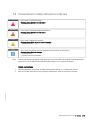
DANGER
WARNING
CAUTION
NOTICE
Note:
In the event of immediate danger.
Consequences: Death or serious injury
• Remedial action
In the event of potentially dangerous situations.
Consequences: Death or serious injury
• Remedial action
In the event of dangerous situations.
Consequences: Minor injury or material damage
• Remedial action
In the event of a situation involving potentially adverse effects on the product.
Consequences: Material damage.
• Remedial action
• Additional product information
This manual contains highlighted safety warnings in accordance with the US ANSI Z535 standard which
begin with one of the signal words listed above depending on the severity of the hazard.
Safety instructions
Read and familiarize yourself with all safety notices before starting up or repairing the product.
Pass on all safety instructions to your operating, maintenance, repair and transport personnel.
TIM-ID: 0000000881 - 018
1.
2.
MS150094/01E 2012-08 | Safety | 13
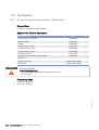
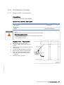
2 Product Summary
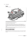
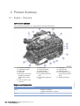
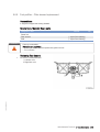
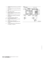
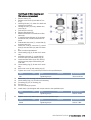
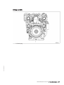
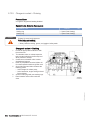
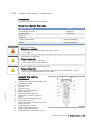
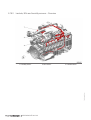
2.1 Engine – Overview
12/16 V 2000 C66/S96
This overview also applies to 16 V 2000 C66 and 16 V 2000 S96 engines.
Exhaust turbocharger
Air intake/air supply
EGR cooler
Intercooler
Monitoring, control and
regulation equipment,
general electr. equip‐
ment
6 Lube oil system / lube
oil circuit
7
8
9
10
11
Power supply
Cooling air system
Coolant system
Mounting / support
Fuel system (low pres‐
sure)
12 Fuel system (high pres‐
sure)
13
14
15
16
Valve gear
Cylinder head
Exhaust system
PTO systems, driving
end and free end (cou‐
pling)
17 Starting equipment
Engine model designation
Key to the engine model designation
12/16
Number of cylinders
V
Cylinder arrangement: V engine
2000
Series
14 | Product Summary | MS150094/01E 2012-08
TIM-ID: 0000023527 - 002
1
2
3
4
5
Key to the engine model designation
C/S
Application: C, charge-air cooling in internal circuit, with
piston cooling
Application S: Exhaust turbocharging with supercharger
Application segment (0, 1, 2,...,9)
6
Design index (0, 1, 2,...,9)
TIM-ID: 0000023527 - 002
6/9
MS150094/01E 2012-08 | Product Summary | 15
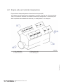
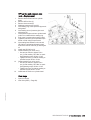
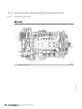
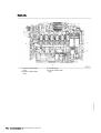
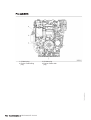
2.2 Engine side and cylinder designations
Engine sides are always designated as viewed from the driving end (KS).
The cylinders of the left engine side are designated "A" and those of the right side "B" (as per DIN ISO
1204). The cylinders of each bank are numbered consecutively, starting with No. 1 at the driving end.
Other components are numbered in the same way, i.e. starting with No. 1 on driving end.
3 Right engine side
4 KS = Driving end
TIM-ID: 0000002185 - 010
1 Left engine side
2 KGS = Free end
16 | Product Summary | MS150094/01E 2012-08
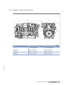
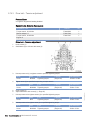
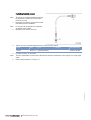
2.3 Engine – Main dimensions
Engine model / Dimension
Engine model / Dimension
12 V 2000 C66/S96
16 V 2000 C66/S96
Length (A)
approx. 2028 mm
approx. 2378 mm
Width (B)
approx. 1276.5 mm
approx. 1287 mm
Height (C)
approx. 1429 mm
approx. 1442 mm
TIM-ID: 0000023835 - 001
Item
MS150094/01E 2012-08 | Product Summary | 17
2.4 Firing order
Firing order for 12 / 16 V 2000 C66/S96 engines
Firing order
12 V
A1-B5-A5-B3-A3-B6-A6-B2-A2-B4-A4-B1
16 V
A1-B5-A3-A5-B2-B8-A2-A8-B3-A7-B4-B6-A4-A6-B1-B7
TIM-ID: 0000023721 - 001
Number of cylin‐
ders
18 | Product Summary | MS150094/01E 2012-08
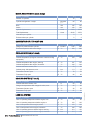
2.5 Technical Data
2.5.1
12/16V 2000 C66 engine data
Explanation:
DL
BL
A
G
R
L
N
X
Ref. value: Continuous power
Ref. value: Fuel stop power
Design value
Guaranteed value
Guideline value
Limit value, up to which the engine can be operated, without change (e.g. of power setting)
Not yet defined value
Not applicable
Applicable
Engine model
Application group
12V2000
C66
16V2000
C66
5B
5B
Intake air temperature
°C
25
25
Charge-air coolant temperature
°C
45
45
Barometric pressure
mbar
1000
1000
Site altitude above sea level
m
100
100
POWER-RELATED DATA (power ratings are net brake power as per ISO 3046)
Number of cylinders
12
16
Rated engine speed
A
rpm
2100
2100
Effective power (w/o fan) (Fuel stop power ISO 3046)
A
kW
783
970
12
16
GENERAL CONDITIONS (for maximum power)
TIM-ID: 0000024846 - 002
Number of cylinders
Intake depression (new filter)
A
mbar
15
15
Intake depression, max.
L
mbar
50
50
Exhaust overpressure
A
mbar
30
30
Exhaust gas overpressure, max.
L
mbar
100
100
Fuel temperature at engine inlet connection
R
°C
37
37
Fuel temperature at engine inlet connection, max (w/o power re‐ L
duction)
°C
65
65
12
16
0.35
0.35
CONSUMPTION
Number of cylinders
Lube oil consumption after 100 h runtime (B = hourly fuel con‐
sumption)
R
% of B
MS150094/01E 2012-08 | Product Summary | 19
MODEL RELATED DATA (basic design)
Number of cylinders
12
16
Number of cylinders
12
16
90
90
Cylinder arrangement: V angle
Degrees
(°)
Bore
mm
135
135
Stroke
mm
156
156
Cylinder displacement
Liters
2.233
2.233
Total displacement
Liters
26.80
35.73
Inlet valves per cylinder
2
2
Exhaust valves per cylinder
2
2
12
16
COMBUSTION AIR / EXHAUST GAS
Number of cylinders
Charge-air pressure before cylinder
R
bar abs
3.95
3.80
Exhaust temperature after turbocharger
R
°C
390
390
12
16
COOLANT SYSTEM (HT circuit)
Number of cylinders
Coolant temperature (at engine connection: outlet to cooling
equipment)
A
°C
100
100
Coolant temperature after engine, warning
R
°C
101
101
Coolant temperature after engine, shutdown
L
°C
104
104
Coolant antifreeze content, max.
L
%
50
50
Coolant pump: inlet pressure, max.
L
bar
1.3
1.3
Thermostat: Starts to open
R
°C
79
79
Thermostat: Fully open
R
°C
92
92
12
16
Number of cylinders
Coolant antifreeze content, max.
L
%
50
50
Charge-air temperature after charge-air cooler, max.
L
°C
95
95
Thermostat: Starts to open
R
°C
38
38
Thermostat: Fully open
R
°C
51
51
12
16
LUBE OIL SYSTEM
Number of cylinders
Lube oil operating temperature before engine, from
R
°C
80
80
Lube oil operating temperature before engine, to
R
°C
103
103
Lube oil temperature before engine, alarm
R
°C
103
103
Lube oil temperature before engine, shutdown
L
°C
106
106
Lube oil operating pressure before engine, warning
R
bar
6.0
6.0
Lube oil operating pressure before engine, shutdown
L
bar
5.5
5.5
20 | Product Summary | MS150094/01E 2012-08
TIM-ID: 0000024846 - 002
COOLING SYSTEM (LT circuit)
FUEL SYSTEM
Number of cylinders
12
16
Fuel pressure at engine inlet connection, min. (when engine is
starting)
L
bar
-0.5
-0.5
Fuel pressure at engine inlet connection, min. (when engine is
running),
L
bar
-0.5
-0.5
Fuel pressure at engine inlet connection, max. (when engine is
starting)
L
bar
0.5
0.5
12
16
32
32
12
16
GENERAL OPERATING DATA
Number of cylinders
Coolant preheating: preheating temperature (min.)
R
°C
INCLINATIONS, STANDARD OIL SYSTEM (reference: waterline)
Number of cylinders
Longitudinal inclination, continuous max. driving end down (Op‐ L
tion: max. operating inclinations)
Degrees
(°)
15
15
Longitudinal inclination, continuous max. driving end up (Option: L
max. operating inclinations)
Degrees
(°)
15
15
Transverse inclination, continuous max. (option: max. operating L
inclinations)
Degrees
(°)
15
15
12
16
CAPACITIES
Number of cylinders
Engine coolant capacity, engine side (without cooling equip‐
ment)
R
Liters
63
70
Charge-air coolant, engine side
R
Liters
25
28
Total engine oil capacity at initial filling (standard oil system)
(Option: max. operating inclinations)
R
Liters
103
127
Oil pan capacity at dipstick mark “min.” (standard oil system)
(Option: max. operating inclinations)
L
Liters
79
97
Oil pan capacity at dipstick mark “max.” (standard oil system)
(Option: max. operating inclinations)
L
Liters
86
106
12
16
ACOUSTICS
TIM-ID: 0000024846 - 002
Number of cylinders
Exhaust noise, unsilenced - BL (free-field sound pressure level
Lp, 1m distance, ISO 6798, +3dB(A) tolerance)
R
dB(A)
106
107
Exhaust noise, unsilenced - BL (sound power level LW, ISO
6798+3 db(A) tolerance)
R
dB(A)
119
120
Engine surface noise with attenuated intake noise (filter) - BL
(free-field sound power level Lp, 1 m distance, ISO 6798,
+2dB(A) tolerance)
R
dB(A)
102
103
Engine surface noise with attenuated intake noise (filter) - BL
(sound power level LW, ISO 6798+2dB(A) tolerance)
R
dB(A)
120
121
MS150094/01E 2012-08 | Product Summary | 21
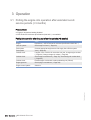
3 Operation
3.1 Putting the engine into operation after extended out-ofservice periods (>3 months)
Preconditions
☑ Engine is stopped and starting disabled.
☑ MTU Fluids and Lubricants Specifications (A001061/..) are available.
Putting into operation after long out-of-service periods (>3 months)
Action
Engine
Depreserve (→ MTU Fluids and Lubricants Specifications A001061/..).
Lube oil system
Check engine oil level (→ Page 69).
Fuel system
Connect appropriate equipment to fuel supply line to fill the system.
Fuel system
Vent (→ Page 56).
Coolant circuit
If engine is out of service for more than one year, change engine coolant
(→ Page 80). Change charge-air coolant (→ Page 89).
Coolant circuit
Check engine coolant level (→ Page 79); Check charge-air coolant level
(→ Page 88).
Coolant circuit
Preheat engine coolant with coolant preheating unit (if fitted).
Engine governor
Check plug-in connections (→ Page 108).
Engine control system
Switch on.
TIM-ID: 0000010073 - 002
Item
22 | Operation | MS150094/01E 2012-08
3.2 Putting the engine into operation after scheduled out-ofservice-period
Preconditions
☑ Engine is stopped and starting disabled.
Putting into operation
Action
Lube oil system
Check engine oil level (→ Page 69).
Coolant circuit
Check engine coolant level (→ Page 79), check charge-air coolant level
(→ Page 88).
Coolant circuit
Preheat engine coolant with coolant preheating unit, if fitted.
Fuel prefilter (if fitted)
Drain water and contaminants, see manufacturer's documentation.
Engine control system
Switch on.
TIM-ID: 0000010642 - 002
Item
MS150094/01E 2012-08 | Operation | 23
3.3 Tasks after extended out-of-service periods (>3 weeks)
Tasks after extended out-of-service periods (>3 weeks)
Operate fuel treatment system for at least 5 minutes.
Start up fuel treatment system (→ Page 26).
Shut down fuel treatment system (→ Page 34).
TIM-ID: 0000007730 - 005
Note:
1.
2.
24 | Operation | MS150094/01E 2012-08
3.4 Checks prior to start-up
Checks prior to start-up
1.
2.
3.
4.
5.
6.
Result:
TIM-ID: 0000007736 - 005
7.
Result:
Check tank and the entire pipework for cleanness. If microorganisms are detected:
a) Clean affected components.
b) Disinfect affected components with biocides (→ MTU Fluids and Lubricants Specifications
A001061/..).
Close drain valves on housing.
Open all supply and discharge valves.
Switch on fuel treatment system (→ Page 29).
Check direction of rotation of pump.
Vent bypass and fuel lines of the system.
a) Open ball valve for pressure tank.
b) Open ball valve for overflow tank.
c) Close ball valve at the inlet to the fuel treatment system.
Bypass line is vented via the overflow tank.
d) Open ball valve at the inlet to the fuel treatment system.
Check the fuel treatment system for leaks.
The fuel treatment system is ready for operation.
MS150094/01E 2012-08 | Operation | 25
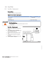
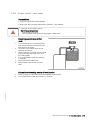
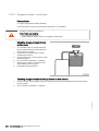
3.5 Fuel treatment system – Putting into operation
Fuel treatment system – Overview
1.
2.
Result:
Switch on fuel treatment system (→ Page 29).
Check the differential pressure at differential pressure gauge (8). Differential pressure in a new system:
0.1 bar to 0.3 bar.
If no differential pressure is measured, the coalescer filter element is probably being bypassed.
1. Remove coalescer filter element (→ Page 103).
2. Check sealing faces on coalescer filter element and in the pressure tank.
Initial operation: HAT
Note:
2.
3.
Result:
4.
5.
6.
Note:
7.
8.
Result:
Replace fuel filter on engine (→ Page 58).
Determine the suction pressure upstream of the engine-mounted fuel delivery pump.
Install a pressure gauge in the fuel supply line from the shipyard-side fuel system to the engine.
Switch on fuel treatment system and operate it for some minutes (→ Page 29).
Fuel is sucked from the tank, dirt particles and water are filtered and separated, then the fuel is delivered
via the overflow tank back to the tank. Water which has settled in the tank is separated.
Start engine (→ Page 28).
Run engine at idling speed.
Check suction pressure (see technical data of the engine) at the engine-mounted fuel delivery pump.
If the suction pressure is within the permissible limits and engine operation is satisfactory:
Increase engine speed to 1000 rpm and monitor suction pressure.
Check suction pressure at the engine-mounted fuel delivery pump.
If the values are within the limits specified by the manufacturer, the system is ready to start filter replace‐
ment simulation with the engine running as part of the Harbor Acceptance Tests.
26 | Operation | MS150094/01E 2012-08
TIM-ID: 0000007738 - 005
1.
Simulation of filter replacement with the engine running: HAT
1.
2.
3.
4.
Result:
5.
Result:
6.
Note:
7.
Result:
Switch on fuel treatment system (→ Page 29).
Start engine (→ Page 28).
Run engine at idling speed.
Close ball cock (5) at the inlet to the fuel treatment system.
The pressure upstream of the fuel treatment system increases until the overflow valve at the pump unit
opens and fuel flows through bypass (3) and bypass (2).
Open ball cock (19).
Fuel emerges. If no fuel emerges:
• Open ball cock (5) at the inlet to the fuel treatment system.
• No function of bypasses (2) and (3); carry out functional test of bypasses (2) and (3).
Check suction pressure (see technical data of the engine) at the fuel delivery pump.
If the suction pressure is within the permissible limits and engine operation is satisfactory:
Increase engine speed to 1000 rpm and monitor suction pressure.
If all engine operating values are within the specified limits, open ball cock (5) at the inlet to the fuel treat‐
ment4 system.
Simulation of power failure (emergency): HAT
1.
2.
3.
4.
Result:
5.
Switch on fuel treatment system (→ Page 29).
Start engine (→ Page 28).
Run engine at idling speed.
Switch off pump (21) on switch cabinet.
The engine-mounted fuel delivery pump sucks fuel via bypass (2) directly from the tank.
Check suction pressure at the engine-mounted fuel delivery pump.
Note:
6.
Result:
If the suction pressure is within the permissible limits and engine operation is satisfactory.
Increase engine speed to 1000 rpm and monitor suction pressure.
If the suction pressure is within the specified limits, simulation was successful.
Simulation of power failure (emergency): SAT
Switch on fuel treatment system (→ Page 29).
Start engine (→ Page 28).
Run engine at idling speed.
Switch off pump (21) on switch cabinet.
The engine-mounted fuel delivery pump sucks fuel via bypass (2) directly from the tank.
Check suction pressure at the engine-mounted fuel delivery pump.
Note:
6.
Result:
If the suction pressure is within the permissible limits and engine operation is satisfactory:
Operate engine at full load and monitor suction pressure.
If the suction pressure is within the specified limits, simulation was successful.
TIM-ID: 0000007738 - 005
1.
2.
3.
4.
Result:
5.
MS150094/01E 2012-08 | Operation | 27
3.6 Starting the engine
Preconditions
☑ Engine is not connected to load.
DANGER
WARNING
Unguarded rotating and moving engine components.
Risk of serious injury – danger to life!
• Before barring or starting the engine, make sure that nobody is in the danger zone.
Engine noise above 85 dB (A).
Risk of damage to hearing!
• Wear ear protectors.
TIM-ID: 0000010107 - 004
Start engine (For required operations, refer to the documentation of the vehicle/plant
manufacturer).
28 | Operation | MS150094/01E 2012-08
3.7 Fuel treatment system – Switching on
Preconditions
☑ The on-board power supply is switched on.
CAUTION
Damage to engine/plant.
Major material damage!
• Before switching on, ensure that the engine/plant is ready for operation.
• Before switching on, ensure that all housings are closed.
• Before switching on, ensure that no work is in progress anywhere on the entire system.
Switching on fuel treatment system
Carry out checks prior to start-up (→ Page 25).
Switch on master switch on switch cabinet.
Signal lamp “Control voltage present” lights up.
Switch on switch for pump.
Signal lamp “Pump running” lights up.
TIM-ID: 0000007731 - 005
1.
2.
Result:
3.
Result:
MS150094/01E 2012-08 | Operation | 29
3.8 Operational checks
DANGER
WARNING
Unguarded rotating and moving engine components.
Risk of serious injury – danger to life!
• Take special care when working on a running engine.
Engine noise above 85 dB (A).
Risk of damage to hearing!
• Wear ear protectors.
Operational checks
Item
Action
Control and display panels
Check readings of operational data (speed, temperature, pressures).
Engine oil
Check engine oil level (→ Page 69).
Engine operation
Check engine visually for leaks and general condition;
Check engine for abnormal running noises, exhaust color and vibra‐
tions.
Check service indicator at air filter (if fitted), see manufacturer's docu‐
mentation.
Exhaust system
Check exhaust color (→ Page 38).
Fuel prefilter (if fitted)
Check reading at differential pressure gauge of fuel prefilter, see manu‐
facturer's documentation.
Intercooler
Check condensate drain(s) for water discharge and obstruction.
Engine coolant pump
Check relief bore (→ Page 84).
Charge-air coolant pump
Check relief bore (→ Page 93).
TIM-ID: 0000025277 - 002
Air filter
30 | Operation | MS150094/01E 2012-08
3.9 Stopping the engine
Preconditions
☑ Engine is not connected to load.
CAUTION
Stopping the engine when it is running at full load causes extreme stress to the engine.
Risk of overheating, damage to components!
• Before stopping the engine, operate it at idle speed until operating temperatures decrease and
stable values are indicated.
Preparation
Item
Action
Engine
Allow the engine to cool down by running idle for approx. 5 minutes.
TIM-ID: 0000010138 - 004
Stop engine (For required operations, refer to the documentation of the vehicle/plant
manufacturer).
MS150094/01E 2012-08 | Operation | 31
3.10 Emergency stop
CAUTION
An emergency stop causes extreme stress to the engine.
Risk of overheating, damage to components!
• Initiate emergency stop only in emergency situations.
Emergency stop
Item
Action
Emergency stop pushbut‐
ton
Press EMERGENCY STOP button.
• Engine is stopped by disconnecting the power supply to the ECU;
• Emergency air shutoff flaps close (if provided);
• signalization (e.g. by horn, beacon) is activated.
After emergency stop
Item
Action
Switchgear cabinet, control Press pushbutton for alarm acknowledgment.
panel etc. (depending on
• Audible and visual signalization stops.
manufacturer)
Engine
Manually open emergency air shutoff flaps (if provided).
TIM-ID: 0000002307 - 002
• Engine is ready for starting.
32 | Operation | MS150094/01E 2012-08
3.11 After stopping the engine
Preconditions
☑ MTU Fluids and Lubricants Specifications (A001061/..) are available.
Note:
If freezing temperatures are to be expected: Coolant pressure sensors installed in vertical position may
be damaged if the coolant does not contain antifreeze additive.
After stopping the engine
Item
Action
Coolant circuit
Drain engine coolant (→ Page 81);
Drain charge-air coolant (→ Page 92) if:
• freezing temperatures are expected and the engine is to remain out of
service for an extended period, but engine coolant has no antifreeze
additive;
• the engine room is not heated;
• the coolant is not kept at a suitable temperature;
• the antifreeze concentration is insufficient for the engine-room tempera‐
ture;
• antifreeze concentration is 50 % and engine-room temperature is below
-40 °C.
Engine control system
Switch off.
TIM-ID: 0000002709 - 005
Air intake and exhaust sys‐ If the engine is to remain out of service for more than 1 week, seal the
tem
engine's air and exhaust sides. If the engine is to remain out of service for
more than 1 month, carry out preservation (→ MTU Fluids and Lubricants
Specifications A001061/..).
MS150094/01E 2012-08 | Operation | 33
3.12 Fuel treatment system – Shutdown
Shutting down fuel treatment system
1.
TIM-ID: 0000007732 - 005
2.
3.
4.
5.
Press the illuminated pushbutton "Water drain" on the switch cabinet until water discharge from the outlet
stops.
Switch off fuel treatment system.
Close ball valve at the inlet to the fuel treatment system.
Close ball valve at the outlet of the fuel treatment system.
Open drain valve until pressure has escaped from fuel treatment system.
34 | Operation | MS150094/01E 2012-08
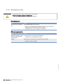
3.13 Plant cleaning
Preconditions
☑ Engine is stopped and starting disabled.
☑ Operating voltage is not present.
Special tools, Material, Spare parts
Designation / Use
Part No.
Qty.
Steam jet cleaner
-
1
30390
1
Cleaner (Hakupur 312)
WARNING
WARNING
CAUTION
NOTICE
Compressed air
Risk of injury!
• Do not direct compressed-air jet at persons.
• Wear protective goggles / safety mask and ear protectors.
Water jet.
Risk of injury and scalding!
• Do not direct water jet at persons.
• Wear protective clothing, gloves, and goggles / safety mask.
Excessive reaction time of cleaning agents on components.
Damage to component!
• Observe manufacturer's instructions.
• Wear protective clothing, gloves, and goggles / safety mask.
Dry with compressed air.
Damage to component!
• Never aim compressed air directly at electronic components.
Plant cleaning
1.
2.
TIM-ID: 0000010171 - 024
3.
4.
5.
Note:
Carry out plant cleaning only in areas where an appropriate oil separator is provided (environmental pro‐
tection).
Prior to putting the cleaning unit into operation, read the Operating Instructions of the water/steam jet unit
carefully and observe the safety precautions.
During external cleaning of the plant with water/steam-jet units, the pressure of the high-pressure jet
(cleaning jet) must not exceed 50 bar. A minimum distance between spray nozzle and plant of 1 m must
be observed. The temperature of the cleaning medium must not exceed 80 °C.
For external cleaning with high-pressure jet, use a flat-mouth nozzle only.
Carry out external cleaning as follows:
a) Seal all openings in a suitable fashion.
b) Remove coarse dirt.
c) Spray on cleaner sparingly and leave it for 1 to 5 minutes.
d) Use the high-pressure jet to remove the loosened dirt.
Never aim compressed air directly at electronic components.
e) Dry engine.
MS150094/01E 2012-08 | Operation | 35
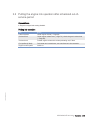
4 Maintenance
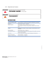
4.1 Maintenance task reference table [QL1]
The maintenance tasks and intervals for this product are defined in the Maintenance Schedule. The
Maintenance Schedule is a stand-alone publication.
Task
Maintenance tasks
W0500
Check engine oil level.
(→ Page 69)
W0501
Visually inspect engine for leaks and general condition.
(→ Page 30)
W0502
Check intercooler drain(s).
(→ Page 30)
W0503
Check signal ring position of service indicator on air filter.
(→ Page 30)
W0505
Check relief bores of water pump(s).
(→ Page 30)
W0506
Check engine for abnormal running noises, exhaust color
and vibrations.
(→ Page 30)
W0507
Drain water and contaminants from fuel prefilter.
(→ Page 30)
W0508
Check reading on differential pressure gauge of fuel prefilter. (→ Page 30)
W1001
Replace fuel filter or fuel filter element.
(→ Page 58)
W1003
Check drive belt condition and tension, replace if necessary.
(→ Page 94)
W1005
Replace air filter.
(→ Page 65)
W1006
Replace fuel injectors.
(→ Page 48)
W1008
Replace engine oil filter when changing engine oil, or when
the interval (years) is reached, at the latest.
(→ Page 71)
W1009
Check layer thickness of the oil residue, clean out and re‐
place filter sleeve, at each oil change, at the latest.
(→ Page 72)
W1178
Replace pressure pipe neck in cylinder head.
(→ Page 54)
W1207
Check valve clearance, adjust if necessary. Attention!First
adjustment after 1,000operating hours!
(→ Page 44)
W1244
Check function of rod electrode.
(→ Page 101)
W1245
Check alarm function of differential pressure gauge.
(→ Page 100)
W1246
Check pump capacity.
(→ Page 102)
W1523
Check operation of flaps and actuators.
(→ Page 68)
W1525
Replace NOx sensor.
(→ Page 110)
W1526
Replace Lambda sensor.
(→ Page 110)
W1547
Replace oil mist separator.
(→ Page 43)
W1636
Reset drift correction parameters (CDC) and enter coding of
injectors (IIG).
(→ Page 117)
Table 1: Maintenance task reference table [QL1]
36 | Maintenance | MS150094/01E 2012-08
TIM-ID: 0000022887 - 003
The task numbers in this table provide reference to the maintenance tasks specified in the Maintenance
Schedule.
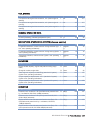
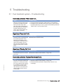
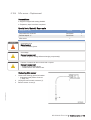
5 Troubleshooting
5.1 Fuel treatment system – Troubleshooting
Illuminated pushbutton “Water alarm” is lit.
Cause
Corrective action
When the maximum water level
is reached, the water level elec‐
trode opens the water drain
valve and water is discharged. If
the opening period of the valve
exceeds a preset limit (4 mi‐
nutes), the pump will switch off
and an alarm is initiated.
1. Press illuminated pushbutton “Water alarm” to acknowledge.
2. In addition to the automatic water drain function, water can also
be drained manually. To do so, press the illuminated pushbutton
“Water drain” to open the drain valve.
Signal lamp “Pump fault” is lit.
Cause
The drive motor is equipped with
an overload protection. If the
maximum permissible current
consumption is exceeded, e.g. in
case of a blockage or dry-run‐
ning, the motor protection relay
triggers and the pump is switch‐
ed off.
Corrective action
u Reset motor protection relay.
Signal lamp “Warning filter” is lit.
Cause
The differential pressure exceed‐
ed 1.3 bar.
Corrective action
u Replace coalescer filter element (→ Page 103).
Illuminated pushbutton “Replace filter element” is lit.
TIM-ID: 0000007734 - 006
Cause
The max. permissible differential
pressure of 1.5 bar was exceed‐
ed. If the coalescer filter element
is not replaced, pressure will in‐
crease further and the safety
valve will open. Fuel will be led
via the bypass directly into the
overflow tank.
Corrective action
1. Replace coalescer filter element (→ Page 103).
2. Press illuminated pushbutton “Replace filter element” to ac‐
knowledge.
MS150094/01E 2012-08 | Troubleshooting | 37
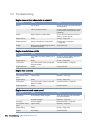
5.2 Troubleshooting
Engine does not turn when starter is actuated
Component
Cause
Action
Battery
Low or faulty
Charge or replace (see manufacturer's
documentation).
Cable connections faulty
Check if cable connections are proper‐
ly secured (see manufacturer's docu‐
mentation).
Starter
Engine cabling or starter faulty
Check cable connections for secure
seating ; contact Service.
Engine wiring
Faulty
Check (→ Page 109).
Engine governor
Plug-in connections possibly loose
Check plug-in connections
(→ Page 108).
Engine
Running gear blocked (engine cannot
be barred manually)
Contact Service.
Engine turns but does not fire
Component
Cause
Action
Starter
Poor rotation by starter: Battery low or
faulty
Charge or replace battery (see manu‐
facturer's documentation).
Engine wiring
Faulty
Check (→ Page 108).
Fuel system
Air in fuel system, if fault occurs after
filling the system.
Vent fuel system (→ Page 56).
Engine governor
Faulty
Contact Service.
Engine fires unevenly
Component
Cause
Action
Fuel injection equip‐
ment
Injector faulty
Replace (→ Page 48).
Engine wiring
Faulty
Check (→ Page 109).
Fuel system
Air in fuel system, if fault occurs after
filling the system.
Vent fuel system (→ Page 56).
Engine governor
Faulty
Contact Service.
Component
Cause
Action
Fuel supply
Fuel prefilter (if fitted) clogged.
Clean filter element (see manufactur‐
er's documentation).
Fuel filter clogged
Replace (→ Page 58).
Air supply
Air filter clogged
Replace air filter (→ Page 65).
Fuel injection equip‐
ment
Injector faulty
Replace (→ Page 48).
Engine wiring
Faulty
Check (→ Page 109).
Engine
Overloaded
Contact Service.
38 | Troubleshooting | MS150094/01E 2012-08
TIM-ID: 0000025278 - 001
Engine does not reach rated speed
Engine speed not steady
Component
Cause
Action
Fuel injection equip‐
ment
Injector faulty
Replace (→ Page 48).
Speed sensor
Faulty
Contact Service.
Fuel system
Air in fuel system, if fault occurs after
filling the system.
Vent fuel system (→ Page 56).
Engine governor
Faulty
Contact Service.
Charge-air temperature too high
Component
Cause
Action
Engine coolant
Engine coolant treatment incorrect
Check (MTU test kit).
Intercooler
Contaminated
Contact Service.
Engine room
Air-intake temperature too high
Check fan;
check air inlet/outlet ducts.
Charge-air pressure too low
Component
Cause
Action
Air supply
Air filter clogged
Replace air filter (see manufacturer's
documentation).
Intercooler
Contaminated
Contact Service.
Exhaust turbocharger Faulty
Contact Service.
Coolant leaks at intercooler
Component
Cause
Action
Intercooler
Leaking, major coolant discharge
Contact Service.
Component
Cause
Action
Air supply
Air filter clogged
Replace air filter (see manufacturer's
documentation).
Fuel injection equip‐
ment
Injector faulty
Replace (→ Page 48).
Engine
Overloaded
Contact Service.
Component
Cause
Action
Engine oil
Too much oil in engine
Drain engine oil (→ Page 70).
Oil mist fine separator of crankcase
breather clogged
Replace (→ Page 43).
Black exhaust gas
TIM-ID: 0000025278 - 001
Blue exhaust gas
Exhaust turbocharger Faulty
Contact Service.
Cylinder head
Piston rings
Cylinder liner
MS150094/01E 2012-08 | Troubleshooting | 39
White exhaust gas
Component
Cause
Action
Engine
Not at operating temperature
Run engine to reach operating temper‐
ature.
Fuel system
Water in fuel
Check fuel system at fuel prefilter
Drain fuel prefilter (→ Page 60).
Leaking
Contact Service.
TIM-ID: 0000025278 - 001
Intercooler
40 | Troubleshooting | MS150094/01E 2012-08
6 Task Description
6.1 Engine
6.1.1
Engine – Barring manually
Preconditions
☑ Engine is stopped and starting disabled.
Special tools, Material, Spare parts
Designation / Use
DANGER
Part No.
Qty.
Barring tool
F6783914
1
Ratchet
F30006212
1
Unguarded rotating and moving engine components.
Risk of serious injury – danger to life!
• Before barring or starting the engine, ensure that nobody is in the danger zone.
• After working on the engine, check that all protective devices have been reinstalled and all tools
removed from the engine.
Engine – Barring manually
1.
2.
TIM-ID: 0000002527 - 002
Result:
Fit ratchet with barring tool on barring tool connection at the vibration damper on engine free end.
Rotate crankshaft in engine direction of rotation. Apart from the normal compression resistance, there
should be no resistance.
If the resistance exceeds the normal compression resistance, contact Service.
MS150094/01E 2012-08 | Task Description | 41
6.1.2
DANGER
Engine – Barring with starting system
Unguarded rotating and moving engine components.
Risk of serious injury – danger to life!
• Before barring or starting the engine, ensure that nobody is in the danger zone.
• After working on the engine, check that all protective devices have been reinstalled and all tools
removed from the engine.
Engine – Barring with starting system
Bar engine, preventing it from firing, see documentation of vehicle/plant manufacturer.
Do not actuate starter for more than 10 seconds.
Repeat this procedure after approx. 20 seconds if required.
TIM-ID: 0000010695 - 002
1.
2.
3.
42 | Task Description | MS150094/01E 2012-08
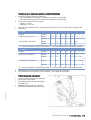
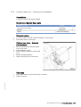
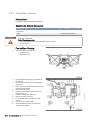
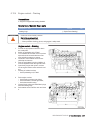
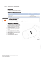
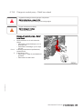
6.2 Crankcase Breather
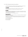
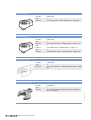
6.2.1
Crankcase breather – Oil mist fine separator replacement
Preconditions
☑ Engine is stopped and starting disabled.
Special tools, Material, Spare parts
Designation / Use
WARNING
Part No.
Engine oil
Oil mist fine separator
(→ Spare Parts Catalog)
O-ring
(→ Spare Parts Catalog)
Qty.
Hot oil.
Oil can contain combustion residues which are harmful to health.
Risk of injury and poisoning!
• Wear protective clothing, gloves, and goggles / safety mask.
• Avoid contact with skin.
• Do not inhale oil vapor.
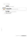
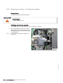
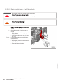
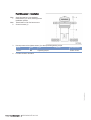
Replacing oil mist fine separator
1.
TIM-ID: 0000018590 - 005
2.
3.
4.
Loosen screws (1) and remove together
with retainer (2).
Replace oil mist fine separator (3).
Check O-ring (4), replace if necessary.
Replace further oil mist fine separators in
the same way.
MS150094/01E 2012-08 | Task Description | 43
6.3 Valve Drive
6.3.1
Valve clearance – Check and adjustment
Preconditions
☑ Engine is stopped and starting disabled.
☑ Engine coolant temperature is max. 40 °C.
☑ Valves are closed.
Special tools, Material, Spare parts
Designation / Use
WARNING
Part No.
Qty.
Feeler gauge
Y4345893
1
Barring device
F6783914
1
Ratchet
F30006212
1
Double-head box wrench
F30002800
1
Ring socket, 19 mm
F30038493
1
Torque wrench, 10-60 Nm
F30510423
1
Valve gear is moving.
Risk of crushing!
• Keep hands clear of the danger zone when barring the engine.
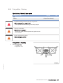
Preparatory steps
u
Remove cylinder head cover (→ Page 47).
Positioning A1 piston at TDC
Install barring device.
Release plug screw (1) and remove.
Using ratchet and barring device, rotate
crankshaft in engine direction of rotation un‐
til the bore (2) on the flywheel is visible in
the center of the exposed opening.
TIM-ID: 0000023895 - 003
1.
2.
3.
44 | Task Description | MS150094/01E 2012-08
Checking valve clearance at two crankshaft positions
1.
2.
3.
Check TDC position of piston in cylinder A1:
• If the rocker arms are unloaded on cylinder A1, the piston is in firing TDC.
• If the rocker arms are loaded on cylinder A1, the piston is in overlap TDC.
Check valve clearance with cold engine:
• Inlet (E) = 0.3 mm;
• Exhaust (A) = 0.4 mm.
Check all valve clearances at two crankshaft positions (firing TDC and overlap TDC) according to the
table below.
12 V 2000
Position
Cylinder
1
2
3
4
5
6
Firing TDC in cylinder A1
Bank A
EA
E-
-A
E-
-A
--
Bank B
E-
--
-A
E-
EA
-A
Bank A
--
-A
E-
-A
E-
EA
Bank B
-A
EA
E-
-A
--
E-
Overlap TDC in cylinder A1
7
8
“E” = inlet valve clearance adjustment permitted, “A” = exhaust valve clearance adjustment permitted
16 V 2000
Position
Cylinder
1
2
3
4
5
6
Firing TDC in cylinder A1
Bank A
E A
- A
E A
E -
-A
E - - -
Bank B
E -
- A
- -
- -
E A E - EA -
Bank A
- -
E -
- -
- A
E -
-A
EA E
A
Bank B
-A
E -
E A
E A
- -
-A
--
Overlap TDC in cylinder A1
7
8
- A
E-
“E” = inlet valve clearance adjustment permitted, “A” = exhaust valve clearance adjustment permitted
4.
5.
Use feeler gauge to determine the distance between valve bridge and rocker arm.
If the deviation from the reference value exceeds 0.1 mm, adjust valve clearance.
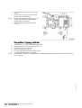
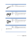
Valve clearance adjustment
1.
2.
TIM-ID: 0000023895 - 003
3.
Loosen locknut (1) and unscrew adjusting
screw (2) by a few threads.
Insert feeler gauge between valve bridge
and rocker arm.
Readjust adjusting screw (2) so that the
feeler gauge just passes through the gap.
MS150094/01E 2012-08 | Task Description | 45
4.
Tighten locknut (1) with torque wrench to the specified tightening torque, holding the adjusting screw (2)
with Allen key to prevent it from turning.
Name
Size
Locknut
5.
Result:
Type
Tightening torque
Lubricant
Value/Standard
50 Nm +5 Nm
Insert feeler gauge between valve bridge and rocker arm to verify that the gauge just passes through the
gap.
If not, adjust valve clearance again.
Final steps
Insert plug screw and tighten.
Remove barring device.
Install cylinder head cover (→ Page 47).
TIM-ID: 0000023895 - 003
1.
2.
3.
46 | Task Description | MS150094/01E 2012-08
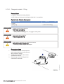
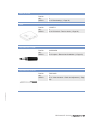
6.3.2
Cylinder head cover – Removal and installation
Preconditions
☑ Engine is stopped and starting disabled.
Special tools, Material, Spare parts
Designation / Use
Part No.
Qty.
Torque wrench, 8-40 Nm
F30043446
1
Ratchet
F30027340
1
Gasket
(→ Spare Parts Catalog)
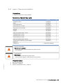
Preparatory steps
1.
2.
On cylinder head covers with crankcase breather: Loosen clamps.
Slide rubber sleeves onto the pipe.
Cylinder head cover – Removal
and installation
1.
2.
3.
4.
5.
Remove cylinder head cover with gasket
from cylinder head.
Clean installation surface.
Check condition of gasket in cylinder head
cover.
Replace damaged gasket(s).
Install cylinder head cover with screws.
Final steps
Slide rubber sleeves onto the relevant pipe connection.
Tighten all clamps.
TIM-ID: 0000000019 - 003
1.
2.
MS150094/01E 2012-08 | Task Description | 47
6.4 Injection Valve / Injector
6.4.1
Injector – Replacement
Special tools, Material, Spare parts
Designation / Use
Injector
Part No.
Qty.
(→ Spare Parts Catalog)
Replacing injector
Remove injector and install new injector (→ Page 49).
TIM-ID: 0000000022 - 013
u
48 | Task Description | MS150094/01E 2012-08
6.4.2
Injector – Removal and installation
Preconditions
☑ Engine is stopped and starting disabled.
Special tools, Material, Spare parts
Designation / Use
Part No.
Qty.
Installation device
F6790085
1
Puller
F6790636
1
Fuel suction device
F30378207
1
Torque wrench, 0.5-5 Nm
0015384230
1
Torque wrench, 20-100 Nm
F30026582
1
Ratchet
F30027340
1
Adapter
F30006234
1
Open-end socket wrench, 19 mm
F30453236
1
Crowfoot wrench, 19 mm
F30027424
1
Crowfoot wrench, 22 mm
F30027425
1
Double-head box wrench
F30011450
1
Open-end socket wrench, 24 mm
F30453238
1
Grease (Kluthe Hakuform 30-10/Emulgier)
X00029933
1
Engine oil
Sealing ring
WARNING
WARNING
(→ Spare Parts Catalog)
Fuels are combustible.
Risk of fire and explosion!
• Avoid open flames, electrical sparks and ignition sources.
• Do not smoke.
Compressed air
Risk of injury!
• Do not direct compressed-air jet at persons.
• Wear protective goggles / safety mask and ear protectors.
TIM-ID: 0000023980 - 002
Preparatory steps
1.
2.
3.
Shut off fuel supply line.
Drain fuel (→ Page 57).
Remove cylinder head cover (→ Page 47).
MS150094/01E 2012-08 | Task Description | 49
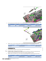
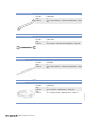
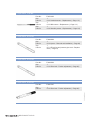
Removing injector
1.
2.
3.
4.
Remove fuel line (1).
Unscrew union nut (2).
Pull out pressure pipe neck (3).
Extract fuel from the exposed bores using
the suction device.
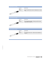
5.
6.
Disconnect terminals (arrow) on injector
and pull out cable lugs.
Remove gasket.
7.
Remove screw (3).
Screw (3) may be installed only once.
Take off hold-down clamp (2).
Use the puller to pull out injector (1).
After removal, seal all openings with suita‐
ble covers.
TIM-ID: 0000023980 - 002
Note:
8.
9.
10.
50 | Task Description | MS150094/01E 2012-08
Installing injector
1.
2.
3.
Note:
4.
5.
Remove all covers before installation.
Clean sealing surface on cylinder head and
protective sleeve.
Coat sealing ring on injector (1) with
grease.
Use either the installation tool or the holddown clamp to press injector (1) into the
cylinder head.
Align square on injector (1) with the seat in
the hold-down clamp (2) and insert injector
by hand straight into the cylinder head.
Place hold-down clamp (2) in position by
hand, ensuring the position is correct.
Installation without installation device
1.
2.
Screw in new screw (3) and press injector (1) carefully into the cylinder head by tightening screw (3).
Name
Size
Type
Screw
M8
Preload torque
Lubricant
Value/Standard
2 Nm +2 Nm
Release screw (3) again and relieve hold-down clamp.
Installation with installation device
1.
2.
Place installation tool on hold-down clamp to press injector (1) carefully into the cylinder head.
Place clamping piece (2) in correct position, screw in screw (3) and tighten snug-fit.
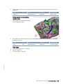
Installing pressure pipe neck
1.
2.
3.
4.
5.
TIM-ID: 0000023980 - 002
6.
7.
Blow out fuel line (1) and pressure pipe
neck (3) with compressed air.
Coat sealing ring with grease.
Coat sealing cone of pressure pipe neck (3)
with engine oil.
Slide pressure pipe neck (3) into cylinder
head until it makes contact with the sealing
ring.
Press in pressure pipe neck (3) by hand un‐
til it will not go any further.
Align HP connection of injector with pres‐
sure pipe neck (3).
Coat thread and shoulder of union nut (2) with engine oil and tighten with torque wrench to the specified
tightening torque.
Name
Union nut
Size
Type
Lubricant
Value/Standard
Preload torque
(Engine oil)
15 Nm + 5 Nm
MS150094/01E 2012-08 | Task Description | 51
9.
Use torque wrench to tighten screw (3) for hold-down clamp (2) to the specified tightening torque.
Name
Size
Type
Lubricant
Value/Standard
Screw
M8
Tightening torque
(Engine oil)
40 Nm +4 Nm
Tighten union nut (2) on pressure pipe neck with torque wrench to the specified tightening torque.
Name
Size
Union nut
Type
Lubricant
Tightening torque
Value/Standard
45 Nm +5 Nm
Installing fuel line
1.
Coat thread and shoulder of union nuts on fuel line (1) with engine oil.
Note:
2.
Position fuel line, ensuring it is free of tension.
Position fuel line (1) so that the union nut with the torque specification faces the fuel rail and the end
without torque specification faces the pressure pipe neck (2), and tighten snug-fit.
3.
Tighten union nut of fuel line (1) on fuel rail to the specified tightening torque using a torque wrench.
Name
Size
Union nut
52 | Task Description | MS150094/01E 2012-08
Type
Lubricant
Value/Standard
Tightening torque
(Engine oil)
45 Nm +5 Nm
TIM-ID: 0000023980 - 002
8.
4.
Tighten union nut of fuel line (1) on pressure pipe neck (2) to the specified tightening torque using a tor‐
que wrench.
Name
Size
Union nut
Type
Lubricant
Value/Standard
Tightening torque
(Engine oil)
37 Nm +3 Nm
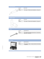
Fitting gasket and connecting
injector cable
1.
Place gasket on cylinder head, ensuring
correct installation position.
2.
Push cable lugs under the terminals (arrow) on the injector and tighten with torque wrench to the speci‐
fied tightening torque.
Name
Size
Type
Lubricant
Value/Standard
Nut
M4
Tightening torque
(Engine oil)
1.5 Nm ±0.25 Nm
Final steps
Install cylinder head cover (→ Page 47).
Open fuel supply line.
Vent fuel system (→ Page 56).
TIM-ID: 0000023980 - 002
1.
2.
3.
MS150094/01E 2012-08 | Task Description | 53
6.5 Fuel System
6.5.1
HP fuel line and pressure pipe neck – Replacement
Preconditions
☑ Engine is stopped and starting disabled.
Special tools, Material, Spare parts
Designation / Use
WARNING
Part No.
Qty.
Torque wrench, 20-100 Nm
F30026582
1
Ratchet adapter
F30027340
1
Adapter
F30006234
1
Socket wrench, 19 mm
F30025897
1
Crowfoot wrench, 19 mm
F30027424
1
Crowfoot wrench, 22 mm
F30027425
1
Double box wrench
F30011450
1
Grease (Kluthe Hakuform 30-10/Emulgier)
X00029933
1
Engine oil
Pressure pipe neck
(→ Spare Parts Catalog)
HP fuel line
(→ Spare Parts Catalog)
Fuels are combustible.
Risk of fire and explosion!
• Avoid open flames, electrical sparks and ignition sources.
• Do not smoke.
Preparatory steps
Shut off fuel supply line.
Drain fuel (→ Page 57).
TIM-ID: 0000012538 - 001
1.
2.
54 | Task Description | MS150094/01E 2012-08
HP fuel line and pressure pipe
neck – Replacement
1.
2.
3.
4.
5.
6.
7.
8.
9.
10.
11.
12.
13.
14.
Remove leak-off fuel line from cylinder
head.
Remove HP fuel line (2).
Remove thrust screw (4).
Withdraw pressure pipe neck (5).
Coat sealing ring of new pressure pipe neck
with grease.
Coat sealing cone of pressure pipe neck
with engine oil.
Insert pressure pipe neck into cylinder head
until it is in contact with the sealing ring.
Fully press in pressure pipe neck by hand.
Tighten thrust screw (4) to specified torque
40 Nm ±5 Nm using torque wrench.
Coat mating face between union nut and
HP fuel line, ball seal and thread on both
ends of the new HP fuel line (2) with engine
oil.
Install new HP fuel line (2).
Observe marking on union nut (1).
• Use torque wrench to tighten union
nut (1) with marking “35+3 Nm” to speci‐
fied tightening torque 35 Nm +3 Nm.
• Tighten union nut (1) without marking to
specified torque 30 Nm +5 Nm.
Observe marking on union nut (3).
• Use torque wrench to tighten union
nut (3) with marking “35+3 Nm” to speci‐
fied tightening torque 35 Nm +3 Nm.
• Tighten union nut (3) without marking to
specified torque 25 Nm +3 Nm.
Install leak-off fuel line on cylinder head.
Final steps
Open fuel supply.
Vent fuel system (→ Page 56).
TIM-ID: 0000012538 - 001
1.
2.
MS150094/01E 2012-08 | Task Description | 55
6.5.2
Fuel system – Venting
Preconditions
☑ Engine is not connected to load.
Fuel system – Venting
The fuel system can only be vented with the engine running.
Start engine (→ Page 28).
Operate the engine until it runs smoothly.
TIM-ID: 0000012554 - 002
Note:
1.
2.
56 | Task Description | MS150094/01E 2012-08
6.5.3
Fuel – Draining
Preconditions
☑ Engine is stopped and starting disabled.
WARNING
Fuels are combustible.
Risk of fire and explosion!
• Avoid open flames, electrical sparks and ignition sources.
• Do not smoke.
Fuel – Draining
Provide a suitable container in which to collect the fuel.
Remove fuel filter (→ Page 58).
Catch fuel as it runs out.
Install fuel filter (→ Page 58).
TIM-ID: 0000004702 - 002
1.
2.
3.
4.
MS150094/01E 2012-08 | Task Description | 57
6.6 Fuel Filter
6.6.1
Fuel filter – Replacement
Preconditions
☑ Engine is stopped and starting disabled.
Special tools, Material, Spare parts
Designation / Use
Filter wrench
Diesel fuel
Easy-change filter
WARNING
Part No.
Qty.
F30379104
1
(→ Spare Parts Catalog)
Fuels are combustible.
Risk of fire and explosion!
• Avoid open flames, electrical sparks and ignition sources.
• Do not smoke.
Fuel filter – Replacement
1.
2.
3.
4.
5.
TIM-ID: 0000012700 - 002
6.
7.
Remove easy-change filter using the filter
wrench.
Clean sealing surface on filter head.
Check sealing ring of the new easy-change
filter and moisten it with fuel.
Fill the new easy-change filter with clean
fuel.
Screw on easy-change filter and tighten
hand-tight.
Replace further fuel filters in the same way.
Vent fuel system (→ Page 56).
58 | Task Description | MS150094/01E 2012-08
6.6.2
DANGER
WARNING
Fuel prefilter – Differential pressure check and adjustment of gauge
Unguarded rotating and moving engine components.
Risk of serious injury – danger to life!
• Take special care when working on a running engine.
Engine noise above 85 dB (A).
Risk of damage to hearing!
• Wear ear protectors.
Differential pressure gauge
adjustment
1.
2.
When installing the new filter element: align
adjustable pointer (2) with pressure-indicat‐
ing pointer (3) of pressure gauge (1).
Verify that differential pressure is within the
limit.
Fuel prefilter – Checking differential pressure
With the engine running at full load or rated power, read off pressure at gauge (1).
If differential pressure as indicated between position of adjustable pointer (2) and pressure indicator of
pressure gauge (3) is ≥ 0.3 bar, flush filter element of the cut-in filter (→ Page 61).
TIM-ID: 0000004926 - 003
1.
2.
MS150094/01E 2012-08 | Task Description | 59
6.6.3
Fuel prefilter – Draining
Preconditions
☑ Engine is stopped and starting disabled.
Special tools, Material, Spare parts
Designation / Use
Diesel fuel
Seal
WARNING
Part No.
Qty.
(→ Spare Parts Catalog)
Fuels are combustible.
Risk of fire and explosion!
• Avoid open flames, electrical sparks and ignition sources.
• Do not smoke.
1.
Cut out the filter to be drained.
I Left filter cut in
II Right filter cut in
2.
Open threaded vent plug (5) of the filter to
be drained.
Unlock drain valve (6) by pressing toggle
and open it.
Drain water and contaminants from the filter
until pure fuel emerges.
Close drain valve (6).
Remove screws securing the cover and
take off cover (2).
Fill filter housing with clean fuel.
Place new seal in cover (2).
Fit cover with gasket and secure it with
screws.
Cut in the cut-out filter again.
Close threaded vent plug (5) when fuel
emerges from system.
3.
4.
5.
6.
7.
8.
9.
10.
11.
60 | Task Description | MS150094/01E 2012-08
TIM-ID: 0000004933 - 004
Fuel prefilter – Draining
6.6.4
Fuel prefilter ‒ Flushing
Special tools, Material, Spare parts
Designation / Use
Part No.
Fuel
Gasket
DANGER
WARNING
WARNING
Qty.
(→ Spare Parts Catalog)
Unguarded rotating and moving engine components.
Risk of serious injury – danger to life!
• Take special care when working on a running engine.
Fuels are combustible.
Risk of fire and explosion!
• Avoid open flames, electrical sparks and ignition sources.
• Do not smoke.
Engine noise above 85 dB (A).
Risk of damage to hearing!
• Wear ear protectors.
Fuel prefilter ‒ Flushing
Cut out clogged filter.
I Left filter cut in
II Right filter cut in
TIM-ID: 0000004937 - 015
1.
MS150094/01E 2012-08 | Task Description | 61
2.
3.
Result:
4.
Open threaded vent plug (5) of filter to be
flushed.
Unlock drain valve (6) by pressing valve
toggle, open it and drain fuel.
Fuel flows from filtered side back to the un‐
filtered side, flushing the filter deposits
downwards out of the filter.
Close threaded vent plug (5) and drain
valve (6).
Fuel prefilter – Topping up with fuel
Stop engine (→ Page 31) and disable engine start.
Remove screws for cover and take off cover (2).
Fill filter housing with clean fuel.
Place new gasket in cover (2).
Fit cover with gasket and secure it with screws.
Check differential pressure (→ Page 59).
If flushing did not lead to an improvement of the differential pressure, replace filter element of fuel prefil‐
ter (→ Page 63).
TIM-ID: 0000004937 - 015
1.
2.
3.
4.
5.
6.
Result:
62 | Task Description | MS150094/01E 2012-08
6.6.5
Fuel prefilter – Filter element replacement
Preconditions
☑ Engine is stopped and starting disabled.
Special tools, Material, Spare parts
Designation / Use
WARNING
Part No.
Diesel fuel
Filter element
(→ Spare Parts Catalog)
Seal
(→ Spare Parts Catalog)
Qty.
Fuels are combustible.
Risk of fire and explosion!
• Avoid open flames, electrical sparks and ignition sources.
• Do not smoke.
Replacing filter element
Cut out the contaminated filter.
I Left filter cut in
II Right filter cut in
TIM-ID: 0000004946 - 004
1.
MS150094/01E 2012-08 | Task Description | 63
2.
3.
4.
5.
6.
7.
8.
9.
10.
11.
12.
13.
TIM-ID: 0000004946 - 004
14.
Open threaded vent plug (5) of contaminat‐
ed filter.
Unlock drain valve (6) by pressing toggle
and open it.
Drain water and contaminants from the fil‐
ter.
Close drain valve (6).
Remove screws securing the cover and
take off cover (2).
Remove spring housing (4) and filter ele‐
ment (3).
Insert new filter element (3) and spring
housing (4).
Fill filter housing with clean fuel.
Place new seal in cover (2).
Fit cover with gasket and secure it with
screws.
Cut in the cut-out filter again.
Close threaded vent plug (5) when fuel
emerges.
Set adjustable pointer of differential pres‐
sure gauge (→ Page 59).
64 | Task Description | MS150094/01E 2012-08
6.7 Air Filter
6.7.1
Air filter – Replacement
Preconditions
☑ Engine is stopped and starting disabled.
TIM-ID: 0000013387 - 003
For air filter replacement, carry out operations as specified by the manufacturer –
filter is plant/vehicle manufacturer's supply.
MS150094/01E 2012-08 | Task Description | 65
6.8 Air Intake
6.8.1
Service indicator – Check
TIM-ID: 0000005482 - 003
See manufacturer's documentation.
66 | Task Description | MS150094/01E 2012-08
6.9 Exhaust Gas Recirculation
Exhaust gas recirculation flaps – Overview
TIM-ID: 0000024288 - 001
6.9.1
MS150094/01E 2012-08 | Task Description | 67
6.9.2
Exhaust gas circulation - Checking flap operation
Preconditions
☑ Engine is stopped and starting disabled.
WARNING
Component is hot.
Risk of burning!
• Wear protective gloves.
Checking exhaust flap operation
1.
For installation position of exhaust flaps, refer to overview (→ Page 67).
2.
Check operability and ease of movement of
exhaust flaps and control linkage by moving
the assembly at the points (arrowed) shown
in the illustration.
If exhaust flap is jammed or sluggish:Con‐
tact Service.
TIM-ID: 0000024000 - 001
Result:
68 | Task Description | MS150094/01E 2012-08
6.10 Lube Oil System, Lube Oil Circuit
6.10.1
Engine oil – Level check
Preconditions
☑ Engine is stopped and starting disabled.
Oil level check prior to engine start
1.
2.
3.
4.
5.
Withdraw oil dipstick from guide tube and
wipe it.
Insert oil dipstick into guide tube up to the
stop, withdraw after approx. 10 seconds
and check oil level.
Oil level must be between "min." and "max."
marks.
Top up to "max." if required (→ Page 70).
Insert oil dipstick into guide tube up to the
stop.
Oil level check after the engine is stopped
5 minutes after stopping the engine, remove oil dipstick from the guide tube and wipe it.
Insert oil dipstick into guide tube up to the stop, withdraw after approx. 10 seconds and check oil level.
Oil level must be between “min.” and "max." marks.
Top up to "max." if required (→ Page 70).
Insert oil dipstick into guide tube up to the stop.
TIM-ID: 0000000032 - 002
1.
2.
3.
4.
5.
MS150094/01E 2012-08 | Task Description | 69
6.10.2
Engine oil – Change
Preconditions
☑ Engine is stopped and starting disabled.
☑ Engine is at operating temperature.
☑ MTU Fluids and Lubricants Specifications (A001061/..) are available.
Special tools, Material, Spare parts
Designation / Use
Engine oil
Sealing ring
WARNING
Part No.
Qty.
(→ Spare Parts Catalog)
Hot oil.
Oil can contain combustion residues which are harmful to health.
Risk of injury and poisoning!
• Wear protective clothing, gloves, and goggles / safety mask.
• Avoid contact with skin.
• Do not inhale oil vapor.
Oil change without semirotary hand pump: Draining oil at drain plug on oil pan
1.
2.
3.
4.
Provide a suitable container to collect the oil.
Remove drain plug and drain oil.
Install drain plug with new sealing ring.
Replace engine oil filter (→ Page 71).
Oil change with semirotary hand pump: Oil extraction
1.
2.
3.
Provide a suitable container to collect the oil.
Extract all oil from oil pan using the semirotary hand pump.
Replace engine oil filter (→ Page 71).
Filling with new oil
1.
2.
TIM-ID: 0000000031 - 005
3.
4.
5.
Open cover on filler neck.
Pour oil in at filler neck up to "max." mark at
oil dipstick.
Close cover on filler neck.
Check engine oil level (→ Page 69).
After oil change and filter replacement, bar
engine with starting system (→ Page 42).
70 | Task Description | MS150094/01E 2012-08
6.11 Oil Filtration / Cooling
6.11.1
Engine oil filter – Replacement
Preconditions
☑ Engine is stopped and starting disabled.
Special tools, Material, Spare parts
Designation / Use
Filter wrench
Engine oil
Oil filter
WARNING
Part No.
Qty.
F30379104
1
(→ Spare Parts Catalog)
Hot oil.
Oil can contain combustion residues which are harmful to health.
Risk of injury and poisoning!
• Wear protective clothing, gloves, and goggles / safety mask.
• Avoid contact with skin.
• Do not inhale oil vapor.
Engine oil filter – Replacement
1.
2.
3.
4.
5.
6.
TIM-ID: 0000014212 - 002
7.
Remove oil filter with filter wrench.
Clean the sealing surface on the oil filter
housing.
Check condition of the new sealing ring and
coat it with oil.
Screw on oil filter and tighten hand-tight.
Replace other oil filters in the same way.
After each oil change and filter replace‐
ment, bar engine with starting system
(→ Page 42).
Check oil level (→ Page 69).
MS150094/01E 2012-08 | Task Description | 71
6.11.2
Centrifugal oil filter – Cleaning and filter sleeve replacement
Preconditions
☑ Engine is stopped and starting disabled.
Special tools, Material, Spare parts
Designation / Use
WARNING
Qty.
Torque wrench, 6-50 Nm
F30027336
1
Cold cleaner (Hakutex 60)
X00056750
1
Filter sleeve
(→ Spare Parts Catalog)
Sealing ring
(→ Spare Parts Catalog)
Sealing ring
(→ Spare Parts Catalog)
Hot oil.
Oil can contain combustion residues which are harmful to health.
Risk of injury and poisoning!
• Wear protective clothing, gloves, and goggles / safety mask.
• Avoid contact with skin.
• Do not inhale oil vapor.
Compressed air
Risk of injury!
• Do not direct compressed-air jet at persons.
• Wear protective goggles / safety mask and ear protectors.
TIM-ID: 0000000934 - 008
WARNING
Part No.
72 | Task Description | MS150094/01E 2012-08
Centrifugal oil filter cleaning and
filter sleeve replacement
1.
2.
16.
Remove clamp (14).
Release cover screw (2) and take off cov‐
er (1).
Carefully lift rotor (11), allow oil to drain and
remove from housing.
Holding the rotor (11) firmly, release rotor
cover nut (3).
Take off rotor cover (4).
Remove filter sleeve (6).
Measure thickness of oil residues on filter
sleeve (6).
If maximum layer thickness of oil residues
exceeds 45 mm, shorten maintenance in‐
terval.
Disassemble rotor tube (7), conical disk (8)
and rotor base (10).
Wash rotor cover (4), rotor tube (7), conical
disk (8) and rotor base (10) with cold clean‐
er.
Blow out with compressed air.
Check sealing ring (9), fit new one if neces‐
sary.
Assemble rotor tube (7), conical disk (8)
and rotor base (10) with sealing ring (9).
Insert new filter sleeve (6) in rotor tube (7)
with the smooth paper surface facing the
outer wall.
Check sealing ring (5), fit new one if neces‐
sary.
Mount rotor cover (4) with sealing ring (5).
17.
Tighten rotor cover nut (3) with torque wrench to the specified torque.
3.
4.
5.
6.
7.
8.
9.
10.
11.
12.
13.
14.
15.
Name
Size
Nut
Lubricant
Tightening torque
Place rotor (11) in housing (12) and check for ease of movement.
Check sealing ring (13), fit new one if necessary.
Fit sealing ring (13) on housing (12).
Fit cover (1).
Fit cover screw (2) by hand.
23.
Install clamp (14) and tighten with torque wrench to the specified torque.
Size
Clamp
24.
Type
Value/Standard
35 Nm to 45 Nm
18.
19.
20.
21.
22.
Name
TIM-ID: 0000000934 - 008
Type
Lubricant
Tightening torque
Value/Standard
8 Nm to 10 Nm
Tighten cover nut (2) with torque wrench to the specified torque.
Name
Screw
Size
Type
Tightening torque
Lubricant
Value/Standard
5 Nm to 7 Nm
MS150094/01E 2012-08 | Task Description | 73
6.12 Coolant Circuit, General, High-Temperature Circuit
6.12.1
Drain and vent points
12 V, 16 V
TIM-ID: 0000025286 - 001
1 Engine coolant vent
74 | Task Description | MS150094/01E 2012-08
Left side
2 Oil drain plug
3 Engine coolant drain
plug
TIM-ID: 0000025286 - 001
1 Engine coolant drain
plug
MS150094/01E 2012-08 | Task Description | 75
Right side
3 Oil drain plug
4 Engine coolant drain
plug
TIM-ID: 0000025286 - 001
1 Engine coolant drain
plug
2 Engine coolant drain
plug
76 | Task Description | MS150094/01E 2012-08
Driving end (KS)
TIM-ID: 0000025286 - 001
1 Oil drain plug
MS150094/01E 2012-08 | Task Description | 77
Free end (KGS)
3 Oil drain plug
4 Engine coolant drain
plug
TIM-ID: 0000025286 - 001
1 Oil drain plug
2 Engine coolant filling
plug
78 | Task Description | MS150094/01E 2012-08
6.12.2
Engine coolant – Level check
Preconditions
☑ Engine is stopped and starting disabled.
☑ MTU Fluids and Lubricants Specifications (A001061/..) are available.
WARNING
Coolant is hot and under pressure.
Risk of injury and scalding!
• Let the engine cool down.
• Wear protective clothing, gloves, and goggles / safety mask.
Checking coolant level at filler
neck:
1.
2.
3.
4.
5.
6.
Turn breather valve on coolant expansion
tank counterclockwise to the first stop and
allow pressure to escape.
Continue to turn breather valve counter‐
clockwise and remove.
Check coolant level (coolant must be visible
at the lower edge of the cast-in eye or at
the marking plate).
Top up with treated coolant as necessary
(→ Page 82).
Check and clean breather valve.
Place breather valve on filler neck and
close.
Coolant-level check by means of level sensor:
Switch on engine control system and check readings on the display.
Top up with treated coolant as necessary (→ Page 82).
TIM-ID: 0000000037 - 004
1.
2.
MS150094/01E 2012-08 | Task Description | 79
6.12.3
Engine coolant – Change
Special tools, Material, Spare parts
Designation / Use
Part No.
Qty.
Coolant
Engine coolant – Change
Drain engine coolant (→ Page 81).
Fill with engine coolant (→ Page 82).
TIM-ID: 0000000036 - 030
1.
2.
80 | Task Description | MS150094/01E 2012-08
6.12.4
Engine coolant – Draining
Preconditions
☑ Engine is stopped and starting disabled.
Special tools, Material, Spare parts
Designation / Use
Part No.
Sealing rings
WARNING
Qty.
(→ Spare Parts Catalog)
Coolant is hot and under pressure.
Risk of injury and scalding!
• Let the engine cool down.
• Wear protective clothing, gloves, and goggles / safety mask.
Engine coolant – Draining
1.
2.
3.
4.
5.
6.
7.
8.
9.
Drain engine coolant:
• At the engine coolant pump elbow;
• At the crankcase, left and right sides;
• At the thermostat housing.
Close all drain valves and install drain plugs
with new sealing rings.
Set breather valve onto filler neck and close
it.
TIM-ID: 0000014583 - 001
10.
Provide an appropriate container to drain
the coolant into.
Switch off preheating unit, if fitted.
Turn breather valve of filler neck on coolant
expansion tank counterclockwise to first
stop and allow pressure to escape.
Continue to turn breather valve counter‐
clockwise and remove.
Draw off precipitated corrosion inhibitor oil
from the expansion tank through filler neck.
Open drain plug at drain point in coolant
line to engine coolant cooler and drain cool‐
ant.
Draining of residual coolant:
• At the preheating unit, if fitted.
MS150094/01E 2012-08 | Task Description | 81
6.12.5
Engine coolant – Filling
Preconditions
☑ Engine is stopped and starting disabled.
☑ MTU Fluids and Lubricants Specifications (A001061/..) are available.
Special tools, Material, Spare parts
Designation / Use
Part No.
Qty.
Coolant
WARNING
WARNING
CAUTION
Coolant is hot and under pressure.
Risk of injury and scalding!
• Let the engine cool down.
• Wear protective clothing, gloves, and goggles / safety mask.
Engine noise above 85 dB (A).
Risk of damage to hearing!
• Wear ear protectors.
Cold coolant in hot engine can cause thermal stress.
Formation of cracks in components!
• Fill / top up coolant only into cold engine.
Preparatory steps
2.
Turn breather valve on coolant expansion
tank counterclockwise to the first stop and
allow pressure to escape.
Continue to turn breather valve counter‐
clockwise and remove.
Engine coolant – Filling
1.
2.
3.
Fill coolant through filler neck on expansion tank or through filling line until coolant level reaches lower
edge of cast-in eye or marking plate.
Check proper condition of breather valve, clean sealing faces if required.
Fit breather valve and close it.
82 | Task Description | MS150094/01E 2012-08
TIM-ID: 0000000034 - 005
1.
Final steps
Start the engine and operate it at idle speed for some minutes.
Check coolant level (→ Page 79), top up with coolant if required.
TIM-ID: 0000000034 - 005
1.
2.
MS150094/01E 2012-08 | Task Description | 83
6.12.6
DANGER
WARNING
Engine coolant pump – Relief bore check
Unguarded rotating and moving engine components.
Risk of serious injury – danger to life!
• Take special care when working on a running engine.
Engine noise above 85 dB (A).
Risk of damage to hearing!
• Wear ear protectors.
Engine coolant pump – Relief bore
check
1.
Result:
TIM-ID: 0000025150 - 001
2.
Check relief bore for oil and coolant dis‐
charge.
• Permissible coolant discharge: up to 10
drops per hour;
• Permissible oil discharge: up to 5 drops
per hour.
If discharge exceeds the specified limits,
contact Service.
If relief bore is dirty:
• Stop engine (→ Page 31) and disable en‐
gine start.
• Clean relief bore with a wire.
84 | Task Description | MS150094/01E 2012-08
6.12.7
Engine coolant – Sample extraction and analysis
Preconditions
☑ Engine is stopped and starting disabled.
☑ MTU Fluids and Lubricants Specifications (A001061/..) are available.
Special tools, Material, Spare parts
Designation / Use
MTU test kit
WARNING
Part No.
Qty.
5605892099/00
1
Coolant is hot and under pressure.
Risk of injury and scalding!
• Let the engine cool down.
• Wear protective clothing, gloves, and goggles / safety mask.
Engine coolant – Sample extraction and analysis
1.
2.
3.
4.
5.
TIM-ID: 0000014607 - 002
6.
7.
Turn breather valve on coolant expansion tank counterclockwise to the first stop and allow pressure to
escape.
Continue to turn breather valve counterclockwise and remove.
Draw off precipitated corrosion inhibitor oil from expansion tank and dispose of oil.
Draw off approx. 1 liter coolant and drain into a clean container.
Using the equipment and chemicals from the MTU test kit, examine coolant for:
• antifreeze concentration;
• corrosion inhibitor concentration;
• pH value.
Fit breather valve and close it.
Engine coolant change intervals (→ MTU Fluids and Lubricants Specifications A001061/..).
MS150094/01E 2012-08 | Task Description | 85
6.12.8
Coolant filter – Replacement
Preconditions
☑ Engine is stopped and starting disabled.
Special tools, Material, Spare parts
Designation / Use
Oil filter wrench
Coolant filter
WARNING
Part No.
Qty.
F30379104
1
(→ Spare Parts Catalog)
Coolant is hot and under pressure.
Risk of injury and scalding!
• Let the engine cool down.
• Wear protective clothing, gloves, and goggles / safety mask.
Coolant filter – Replacement
1.
2.
3.
4.
5.
TIM-ID: 0000006921 - 004
6.
7.
8.
Turn breather valve of coolant expansion
tank counterclockwise (→ Page 14) to the
first stop and allow pressure to escape.
Continue to turn breather valve counter‐
clockwise and remove.
Remove coolant filter using the oil filter
wrench.
Clean the sealing face on the adapter.
Coat sealing ring of the new coolant filter
with engine oil.
Install and tighten coolant filter by hand.
Close breather valve.
Check coolant level (→ Page 79).
86 | Task Description | MS150094/01E 2012-08
6.13 Low-Temperature Circuit
6.13.1
Intercooler – Vent and drain points
12 V, 16 V
TIM-ID: 0000025297 - 002
1 Intercooler vent plugs
MS150094/01E 2012-08 | Task Description | 87
6.13.2
Charge-air coolant – Level check
Preconditions
☑ Engine is stopped and starting disabled.
☑ MTU Fluids and Lubricants Specifications (A001061/..) are available.
WARNING
Coolant is hot and under pressure.
Risk of injury and scalding!
• Let the engine cool down.
• Wear protective clothing, gloves, and goggles / safety mask.
Checking charge-air coolant level
at filler neck:
1.
2.
3.
4.
5.
6.
Turn breather valve on coolant expansion
tank counterclockwise to the first stop and
allow pressure to escape.
Continue to turn breather valve counter‐
clockwise and remove.
Check coolant level (coolant must be visible
at marking plate).
Top up coolant if necessary (→ Page 90).
Check proper condition of breather valve,
clean sealing faces if required.
Fit breather valve and close it.
Checking charge-air coolant level by means of level sensor:
1.
TIM-ID: 0000000042 - 007
2.
Switch on engine control system and check display (coolant level is automatically monitored by engine
control system).
Top up coolant if necessary (→ Page 90).
88 | Task Description | MS150094/01E 2012-08
6.13.3
Charge-air coolant – Change
Special tools, Material, Spare parts
Designation / Use
Part No.
Qty.
Coolant
Charge-air coolant – Change
Drain charge-air coolant (→ Page 92).
Fill with charge-air coolant (→ Page 90).
TIM-ID: 0000000041 - 011
1.
2.
MS150094/01E 2012-08 | Task Description | 89
6.13.4
Charge-air coolant – Filling
Preconditions
☑ Engine is stopped and starting disabled.
☑ MTU Fluids and Lubricants Specifications (A001061/..) are available.
Special tools, Material, Spare parts
Designation / Use
Coolant
Sealing ring
WARNING
WARNING
CAUTION
Part No.
Qty.
(→ Spare Parts Catalog)
Coolant is hot and under pressure.
Risk of injury and scalding!
• Let the engine cool down.
• Wear protective clothing, gloves, and goggles / safety mask.
Engine noise above 85 dB (A).
Risk of damage to hearing!
• Wear ear protectors.
Cold coolant in hot engine can cause thermal stress.
Formation of cracks in components!
• Fill / top up coolant only into cold engine.
Preparatory steps
1.
2.
TIM-ID: 0000000039 - 003
3.
Turn breather valve on coolant expansion
tank counterclockwise to the first stop and
allow pressure to escape.
Continue to turn breather valve counter‐
clockwise and remove.
Remove plug screw from filling point on
coolant line to intercooler.
90 | Task Description | MS150094/01E 2012-08
Charge-air coolant – Filling
1.
2.
3.
4.
Fill treated coolant through filling line or through filler neck of coolant expansion tank until coolant level
reaches marking plate.
Install plug screws of filling points with new sealing rings.
Check proper condition of breather valve, clean sealing faces if required.
Fit breather valve and close it.
Final steps
Start the engine and operate it at idle speed for some minutes.
Check coolant level (→ Page 88).
TIM-ID: 0000000039 - 003
1.
2.
MS150094/01E 2012-08 | Task Description | 91
6.13.5
Charge-air coolant – Draining
Preconditions
☑ Engine is stopped and starting disabled.
Special tools, Material, Spare parts
Designation / Use
WARNING
Part No.
Sealing ring
(→ Spare Parts Catalog)
Sealing ring
(→ Spare Parts Catalog)
Qty.
Coolant is hot and under pressure.
Risk of injury and scalding!
• Let the engine cool down.
• Wear protective clothing, gloves, and goggles / safety mask.
Charge-air coolant – Draining
1.
2.
3.
4.
5.
TIM-ID: 0000000040 - 002
6.
7.
Provide an appropriate container to drain
the coolant into.
Turn breather valve on coolant expansion
tank counterclockwise to the first stop and
allow pressure to escape.
Continue to turn breather valve counter‐
clockwise and remove.
Draw off precipitated corrosion inhibitor oil
from the expansion tank through filler neck.
Open drain plugs and drain coolant at the
following points:
• At the charge-air coolant pump;
• At the intercooler, engine driving end and
free end sides.
Screw in drain plugs with new sealing rings.
Place breather valve on filler neck and
close.
92 | Task Description | MS150094/01E 2012-08
6.13.6
DANGER
WARNING
Charge-air coolant pump – Relief bore check
Unguarded rotating and moving engine components.
Risk of serious injury – danger to life!
• Take special care when working on a running engine.
Engine noise above 85 dB (A).
Risk of damage to hearing!
• Wear ear protectors.
Charge-air coolant pump – Relief
bore check
1.
Result:
TIM-ID: 0000025276 - 001
2.
Check relief bore for oil and coolant dis‐
charge.
• Permissible coolant discharge: up to 10
drops per hour;
• Permissible oil discharge: up to 5 drops
per hour.
If discharge exceeds the specified limits,
contact Service.
If relief bore is dirty:
• Stop engine (→ Page 31) and disable en‐
gine start.
• Clean relief bore with a wire.
MS150094/01E 2012-08 | Task Description | 93
6.14 Belt Drive
6.14.1
Drive belt – Condition check
Preconditions
☑ Engine is stopped and starting disabled.
☑ Guard is removed.
Drive belt – Condition check
Findings
Action
Drive belt A
Singular cracks
None
Drive belt
Belt is oily, shows signs of over‐
heating
Replace (→ Page 98)
Drive belt B
Cracks on entire circumference
Drive belt C
Chunking
TIM-ID: 0000000920 - 010
Item
94 | Task Description | MS150094/01E 2012-08
6.14.2
Drive belt – Tension check
Preconditions
☑ Engine is stopped and starting disabled.
Special tools, Material, Spare parts
Designation / Use
Part No.
Qty.
Tester
Y4345711
1
Belt tension tester, 150-600 N
Y20097429
1
Fan drive – Checking belt tension
1.
2.
3.
4.
5.
6.
Remove protective cover.
Set belt tension tester onto the drive belt in
the middle between the belt pulleys (arrow).
Using pushbutton, press vertically on top
side of drive belt exerting even pressure un‐
til spring engages noticeably.
Do not press any further, otherwise the dis‐
play value will be falsified.
Take off tension tester without changing the
position of the display arm.
Read off measured value at the intersection
of display arm and "KG" scale. For specifi‐
cations, refer to table below.
Application
Fan drive belt
Specification
Specification
Initial installation (new belt)
Operating tension (used belt)
Frequency: 99 ±1 Hz
Frequency: 86 ±1 Hz
Table 2: Measuring belt tension with frequency meter
Application
Fan drive belt
Specification
Specification
Initial installation (new belt, run‐
time 0.5-2 h)
(used belt, runtime 500 h)
Depression depth: 5.6 mm
Depression depth: 7.2 mm
Test force: 188 N
Test force: 188 N
TIM-ID: 0000025518 - 002
Table 3: Measuring depression depth with tension tester
Application
Fan drive belt
Specification
Specification
Initial installation (new belt, run‐
time 0.5-2 h)
(used belt, runtime 500 h)
Static tension: 4000 N
Static tension: 3000 N
Table 4: Measuring static belt tension
7.
8.
If the measured values deviate from the specifications above, adjust drive belt tension (→ Page 96).
Install protective cover.
MS150094/01E 2012-08 | Task Description | 95
6.14.3
Drive belt – Tension adjustment
Preconditions
☑ Engine is stopped and starting disabled.
Special tools, Material, Spare parts
Designation / Use
Part No.
Qty.
Torque wrench, 20-100 Nm
F30026582
1
Ratchet adapter ½"
F30027340
1
Torque wrench, 40-200 Nm
F30027337
1
Engine oil
Drive belt – Tension adjustment
1.
2.
Undo screws (1).
Set distance (A) to 100 mm with screw (2).
3.
Use torque wrench (1) to tighten screws to specified tightening torque.
Size
Type
Lubricant
Value/Standard
Screw
M16x50
Tightening torque
(Engine oil)
180 Nm +18 Nm
Tighten screw (2) to specified torque using a torque wrench.
Name
Size
Type
Lubricant
Value/Standard
Screw
M16x280
Tightening torque
(Engine oil)
70 Nm +7 Nm
5.
6.
Undo screws (3).
Adjust belt tension with screw (4) (→ Page 95).
7.
Use torque wrench to tighten screws (3) to specified tightening torque.
8.
Name
Size
Type
Lubricant
Value/Standard
Screw
M12
Tightening torque
(Engine oil)
74 Nm +7 Nm
Use torque wrench to tighten screw (4) to specified tightening torque.
Name
Size
Type
Lubricant
Value/Standard
Screw
M12x240
Tightening torque
(Engine oil)
30 Nm +3 Nm
96 | Task Description | MS150094/01E 2012-08
TIM-ID: 0000025520 - 001
4.
Name
6.14.4
Drive belt – Replacement
Preconditions
☑ Engine is stopped and starting disabled.
Special tools, Material, Spare parts
Designation / Use
Drive belt
Part No.
Qty.
(→ Spare Parts Catalog)
Fan drive – Drive belt replacement
1.
2.
3.
4.
5.
Note:
6.
7.
8.
When placing the drive belt in the grooves,
no force must be applied.
Fit new drive belt.
Screw in screw (2) until distance (A) is 100
mm.
Adjust and check drive belt tension
(→ Page 96).
Install fan.
Install protective cover.
TIM-ID: 0000025462 - 001
9.
10.
Remove protective cover from radiator.
Remove fan.
Slacken off securing screws (1).
Screw out screw (2) as far as necessary to
allow drive belt removal.
Check belt pulley on radiator bearing mount
and crankshaft for contamination and clean
if necessary.
MS150094/01E 2012-08 | Task Description | 97
6.15 Battery-Charging Generator
6.15.1
Battery-charging generator drive – Drive belt replacement
Preconditions
☑ Engine is stopped and starting disabled.
Special tools, Material, Spare parts
Designation / Use
Mandrel
Part No.
Qty.
8205892861/08
1
Preparatory steps
1.
2.
3.
Remove safety equipment (if fitted).
Remove screws of protective cover (engine free end).
Remove protective cover.
Drive belt – Replacement
1.
2.
3.
4.
5.
6.
7.
Hold adjusting lever at square.
Rotate adjusting lever until drive belt is released.
Use mandrel to lock adjusting lever in position.
Remove drive belt.
Check cleanness of belt pulleys.
Fit new drive belt.
Remove mandrel.
Final steps
Install protective cover.
Install screws of protective cover.
Install safety equipment (if fitted).
Check function of safety equipment (if fitted).
TIM-ID: 0000007424 - 003
1.
2.
3.
4.
98 | Task Description | MS150094/01E 2012-08
6.16 Fuel Supply System
6.16.1
Water drain valve – Check
Water drain valve – Check
Open water drain valve.
Check water outlet for obstructions.
Close water drain valve.
TIM-ID: 0000007733 - 007
1.
2.
3.
MS150094/01E 2012-08 | Task Description | 99
6.16.2
WARNING
Differential pressure gauge – Check
Fuels are combustible.
Risk of fire and explosion!
• Avoid open flames, electrical sparks and ignition sources.
• Do not smoke.
Differential pressure gauge – Check
Switch on fuel treatment system (→ Page 26).
Set the alarm points at the differential pressure gauge to zero.
Alarm is initiated with preset delay.
Reset the alarm points at the differential pressure gauge to the specified values.
TIM-ID: 0000023563 - 001
1.
2.
Result:
3.
100 | Task Description | MS150094/01E 2012-08
6.16.3
Water level probe (3-in-1 rod electrode) – Check
Preconditions
☑ System is put out of service and emptied.
WARNING
Fuels are combustible.
Risk of fire and explosion!
• Avoid open flames, electrical sparks and ignition sources.
• Do not smoke.
Water level probe (3-in-1 rod electrode) – Check
Disconnect plug from water level probe.
Unscrew water level probe.
Disconnect plug from water level probe.
Immerse water level probe into a tank filled with water until water level reaches the thread.
Water drain valve opens.
Leave water level probe in tank.
Alarm must be triggered with the preset delay.
Disconnect plug from water level probe.
Remove water level probe from tank.
Screw in water level probe.
Connect plug for water level probe.
Put the fuel treatment system into operation.
TIM-ID: 0000023558 - 001
1.
2.
3.
4.
Result:
5.
Result:
6.
7.
8.
9.
10.
MS150094/01E 2012-08 | Task Description | 101
6.16.4
WARNING
Pump capacity – Check
Fuels are combustible.
Risk of fire and explosion!
• Avoid open flames, electrical sparks and ignition sources.
• Do not smoke.
Pump capacity – Check
1.
2.
Note:
3.
4.
Install suitable pressure gauge in the intake connection of the pump.
Check pump pressure.
a) Switch on fuel treatment system (→ Page 29).
The pressure limiting valve at the pump might respond and open. Audible noise is caused by overflowing
fuel and can be disregarded.
b) Close ball valve at the outlet of the fuel treatment system.
c) Check pressure at the pressure gauge in the inlet to the fuel treatment system and note down.
Checking pump pressure with reduced suction
a) Reduce suction pressure of pump to -0.8 bar with the shut-off valve at the pump intake side.
b) Check pressure at the pressure gauge in the inlet to the fuel treatment system and note down.
c) Open ball valve at inlet and outlet of fuel treatment system.
Calculate wear limit.
Example:
Measured value (normal condition).
3 bar
Measured value (reduced suction condition).
2.6 bar
TIM-ID: 0000023567 - 001
If the measured value (reduced suction condition) is 10% lower than the measured value (normal con‐
dition), the wear limit is reached. Repair pump (contact Service).
102 | Task Description | MS150094/01E 2012-08
6.16.5
Coalescer filter element – Replacement
Preconditions
☑ System is switched off and starting disabled.
Special tools, Material, Spare parts
Designation / Use
WARNING
CAUTION
CAUTION
Part No.
Qty.
Torque wrench, 6-50 Nm
F30027336
1
Ratchet adapter
F30027339
1
Diesel fuel
Engine oil
Coalescer filter element
(→ Spare Parts Catalog)
Gasket
(→ Spare Parts Catalog)
Fuels are combustible.
Risk of fire and explosion!
• Avoid open flames, electrical sparks and ignition sources.
• Do not smoke.
Contamination of components.
Damage to component!
• Observe manufacturer's instructions.
• Check components for special cleanness.
Incorrect installation of components and lines.
Damage to component!
• Ensure that components/lines are installed so that they are never under tension or strain.
• Ensure correct installation position of components.
Coalescer filter element –
Replacement
TIM-ID: 0000007735 - 007
1.
2.
3.
4.
5.
6.
7.
8.
9.
10.
11.
12.
13.
14.
15.
Close ball valve at the inlet and outlet of the
fuel treatment system.
Open drain valve.
Drain fuel.
Close drain valve.
Remove nut (9) with washer (2).
Remove screws (1).
Remove cover with gasket (10).
Remove nut (3), washer (8) and end
plate (7).
Remove coalescer filter element (4).
Catch fuel as it runs out.
Clean housing with a non-linting cloth, rinse
with fuel if required.
Check housing for corrosion.
Clean housing sealing surfaces.
Install coalescer filter element.
Install end plate (7), washer (8) and nut (3).
MS150094/01E 2012-08 | Task Description | 103
16.
Name
Size
Type
Lubricant
Value/Standard
Nut
M16
Tightening torque
(Engine oil)
30 Nm +3 Nm
Fit gasket (10).
Install cover.
Install screw (1), washer (2) and nut (9).
Tighten nut (9).
Open ball valve at the inlet and outlet of the fuel treatment system.
The fuel treatment system is ready for operation.
TIM-ID: 0000007735 - 007
17.
18.
19.
20.
21.
Result:
Tighten nut (3) to specified tightening torque using a torque wrench.
104 | Task Description | MS150094/01E 2012-08
6.17 Engine Governor
6.17.1
Engine governor – Overview
Screw
Washer
Damper
Engine governor
Connector X3
Screw
Connector X1
Screw for grounding strap
TIM-ID: 0000031588 - 001
1
2
3
4
5
6
7
8
MS150094/01E 2012-08 | Task Description | 105
6.17.2
Engine governor – Removal
Preconditions
☑ Engine is stopped and starting disabled.
Preparatory steps
1.
2.
3.
Observe safety instructions.
Switch off operating voltage.
Note or mark assignment of cables and plugs.
Engine governor – Removal
Remove engine governor as per overview drawing (→ Page 105).
TIM-ID: 0000031586 - 001
u
106 | Task Description | MS150094/01E 2012-08
6.17.3
Engine governor – Installation
Preconditions
☑ Engine is stopped and starting disabled.
Special tools, Material, Spare parts
Designation / Use
Engine oil
Damper
Part No.
Qty.
(→ Spare Parts Catalog)
8
Engine governor – Installation
1.
2.
3.
Install engine governor as per overview drawing (→ Page 105).
Name
Size
Type
Lubricant
Value/Standard
Screw for ground‐
ing strap
M6x12
Tightening torque
(Engine oil)
Max. 8 Nm
Fit connector X1 and X3 on Engine Control Unit and engage locks.
Fit retainers for engine wiring.
Final step
Enable engine start.
TIM-ID: 0000031642 - 001
u
MS150094/01E 2012-08 | Task Description | 107
6.17.4
Engine governor – Checking plug-in connections
Preconditions
☑ Engine is stopped and starting disabled.
Note:
Always use test connectors to enter the connectors. Never use test leads for this purpose.Otherwise the
contacts could be bent.
Checking plug-in connections on engine governor
Check all plug-in connections for secure seating.
Latch connectors if loose.
TIM-ID: 0000000048 - 005
1.
2.
108 | Task Description | MS150094/01E 2012-08
6.18 Wiring (General) for Engine/Gearbox/Unit
6.18.1
Engine wiring – Check
Preconditions
☑ Engine is stopped and starting disabled.
Special tools, Material, Spare parts
Designation / Use
Part No.
Qty.
Isopropyl alcohol
X00058037
1
Engine wiring – Check
1.
2.
3.
4.
5.
6.
Close male connectors that are not plugged in with the protective cap supplied.
Clean dirty connector housings, sockets and contacts with isopropyl alcohol.
Ensure that all sensor connectors are securely engaged.
TIM-ID: 0000000029 - 018
Note:
7.
8.
Check securing screws of cable clamps on engine and tighten loose threaded connections.
Ensure that cables are fixed in their clamps and cannot swing freely.
Check that cable ties are firm, tighten loose cable ties.
Replace faulty cable ties.
Visually inspect the following electrical line components for damage:
• connector housings;
• contacts;
• sockets;
• cables and terminals;
• plug-in contacts.
(→ Contact Service) if cable conductors are damaged.
MS150094/01E 2012-08 | Task Description | 109
6.18.2
Lambda, NOx and humidity sensors – Overview
2 NOx sensor
3 Lambda sensor
TIM-ID: 0000025179 - 001
1 Humidity sensor
110 | Task Description | MS150094/01E 2012-08
6.18.3
Lambda sensor – Replacement
Preconditions
☑ Engine is stopped and starting disabled.
☑ Preparatory steps have been completed.
Special tools, Material, Spare parts
Designation / Use
Part No.
Qty.
Torque wrench, 10-60 Nm
F30510423
1
Ratchet adapter ½"
F30027340
1
Lambda sensor
WARNING
CAUTION
CAUTION
1
Component is hot.
Risk of burning!
• Wear protective gloves.
Overvoltage.
Damage to component!
• Switch off ignition voltage before exchanging component(s).
Fracture of ceramic cell due to shock load or impact.
Damage to component!
• Avoid shock load and impact.
• Handle sensors with extreme care.
Removing lambda sensor
1.
TIM-ID: 0000025194 - 002
2.
3.
Observe the following general information:
• Arrangement and position of sensor
(→ Page 110).
Unplug and remove male connector (1).
Remove sensor via nut (2).
MS150094/01E 2012-08 | Task Description | 111
Installing lambda sensor
Note:
1.
Note:
The sensor is considered defective after be‐
ing exposed to shock load or impact and
must not be used.
Remove the protective cap from the thread
immediately before installation.
2.
Do not wipe off the grease the manufactur‐
er applied on the thread.
Manually screw sensor into bore.
3.
Tighten nut (2) to specified tightening torque using a torque wrench.
4.
Note:
Size
Type
Sensor
M18 x 1.5 Tightening torque
Lubricant
Value/Standard
40 Nm to 60 Nm
Fit male connector (1) and latch.
The CDC parameters must be reset, otherwise the emission certification of the engine is no longer appli‐
cable.
Reset CDC parameters (→ Page 117).
TIM-ID: 0000025194 - 002
5.
Name
112 | Task Description | MS150094/01E 2012-08
6.18.4
NOx sensor – Replacement
Preconditions
☑ Engine is stopped and starting disabled.
☑ Preparatory steps have been completed.
Special tools, Material, Spare parts
Designation / Use
Part No.
Qty.
Torque wrench, 10-60 Nm
F30510423
1
Ratchet adapter ½"
F30027340
1
NOx sensor
WARNING
CAUTION
CAUTION
1
Component is hot.
Risk of burning!
• Wear protective gloves.
Overvoltage.
Damage to component!
• Switch off ignition voltage before exchanging component(s).
Fracture of ceramic cell due to shock load or impact.
Damage to component!
• Avoid shock load and impact.
• Handle sensors with extreme care.
Removing NOx sensor
1.
TIM-ID: 0000025205 - 002
2.
3.
Observe the following general information:
• Arrangement and position of sensor
(→ Page 110).
Unplug and remove male connector (1).
Remove sensor via nut (2).
MS150094/01E 2012-08 | Task Description | 113
Installing NOx sensor
Note:
1.
Note:
The sensor is considered defective after be‐
ing exposed to shock load or impact and
must not be used.
Remove the protective cap from the thread
immediately before installation.
2.
Do not wipe off the grease the manufactur‐
er applied on the thread.
Manually screw sensor into bore.
3.
Tighten nut (2) to specified tightening torque using a torque wrench.
4.
Note:
Size
Type
Sensor
M20 x 1.5 Tightening torque
Lubricant
Value/Standard
50 Nm ±10 Nm
Fit male connector (1) and latch.
The CDC parameters must be reset, otherwise the emission certification of the engine is no longer appli‐
cable.
Reset CDC parameters (→ Page 117).
TIM-ID: 0000025205 - 002
5.
Name
114 | Task Description | MS150094/01E 2012-08
6.18.5
Humidity sensor – Replacement
Preconditions
☑ Engine is stopped and starting disabled.
☑ Preliminary steps are completed.
Special tools, Material, Spare parts
Designation / Use
Part No.
Qty.
Torque wrench, 10-60 Nm
F30510423
1
Ratchet adapter ½"
F30027340
1
Engine
NOx sensor
CAUTION
1
1
Contamination of components.
Damage to component!
• Observe manufacturer's instructions.
• Check components for special cleanness.
NOx sensor – Removal
1.
TIM-ID: 0000025206 - 001
2.
3.
4.
Observe the following general information:
• Layout and position of sensor
(→ Page 110).
Unplug and remove male connector.
Remove screws (1).
Remove sensor (2).
MS150094/01E 2012-08 | Task Description | 115
Humidity sensor – Installation
Note:
1.
Apply lubricant for O-ring sparingly.
Insert sensor (2) in bore, ensuring correct
installation position.
Note:
2.
Take direction of air flow into account.
Screw in screws (1).
3.
Name
Size
Type
Sensor
M6
Tightening torque
Lubricant
Value/Standard
12 Nm +5 Nm
Fit male connector and latch.
TIM-ID: 0000025206 - 001
4.
Use torque wrench to tighten screws (1) to the specified tightening torque.
116 | Task Description | MS150094/01E 2012-08
6.19 Accessories for (Electronic) Engine Governor / Control
System
6.19.1
CDC parameters – Reset with DiaSys®
Preconditions
☑ Engine is stopped and starting disabled.
Resetting CDC parameters (DiaSys® is available)
Note:
u
The CDC parameters must be reset, otherwise the emission certification of the engine is no longer appli‐
cable.
Reset the CDC parameters with DiaSys® (→ Manufacturer's documentation).
Resetting CDC parameters (DiaSys® is not available)
Note:
TIM-ID: 0000029731 - 002
u
The CDC parameters must be reset, otherwise the emission certification of the engine is no longer appli‐
cable.
Contact Service.
MS150094/01E 2012-08 | Task Description | 117
6.19.2
Engine governor and connectors – Cleaning
Preconditions
☑ Engine is stopped and starting disabled.
Special tools, Material, Spare parts
Note:
Designation / Use
Part No.
Qty.
Isopropyl alcohol
X00058037
1
Always use test connectors to enter the connectors. Never use test leads for this purpose.Otherwise the
contacts could be bent.
Engine governor and connectors – Cleaning
1.
2.
3.
Remove coarse dirt from housing surface with isopropyl alcohol.
Remove dirt from connector and cable surfaces with isopropyl alcohol.
Check legibility of cable labels. Clean or replace illegible labels.
Cleaning severely contaminated connectors on the engine governor
Seal unused connectors with the supplied protective cap.
Release the latch and pull off connectors.
Clean connector housings, connector socket housings and all contacts with isopropyl alcohol.
When connectors, sockets and all contacts are dry: Fit connectors and lock them.
TIM-ID: 0000000047 - 009
Note:
1.
2.
3.
118 | Task Description | MS150094/01E 2012-08
6.19.3
Engine governor – Checking plug-in connections
Preconditions
☑ Engine is stopped and starting disabled.
Note:
Always use test connectors to enter the connectors. Never use test leads for this purpose.Otherwise the
contacts could be bent.
Checking plug-in connections on engine governor
Check all plug-in connections for secure seating.
Latch connectors if loose.
TIM-ID: 0000000048 - 005
1.
2.
MS150094/01E 2012-08 | Task Description | 119
7 Appendix A
7.1 List of abbreviations
Abbrevia‐
tion
Meaning
Explanation
ADEC
Advanced Diesel Engine Controller
Engine management system
AL
Alarm
General alarm
ANSI
American National Standards Institute Umbrella organization administering and coordinat‐
ing U.S. standards
ATL
Abgasturbolader
BDM
Backup Data Module
BR
Baureihe
Series
BV
Betriebsstoffvorschrift
MTU Fluids and Lubricants Specifications, Publica‐
tion No. A01061/..
CAN
Controller Area Network
Data bus system, bus standard
CPP
Controllable Pitch Propeller
CR
Common Rail
DIN
Deutsches Institut für Normung e. V.
German Standardization Organization, at the same
time identifier of German standards ("Deutsche In‐
dustrie-Norm")
DIS
Display Unit
Display panel
DL
Default Lost
Alarm: CAN bus missing
DPF
Diesel Particulate Filter
ECS
Engine Control System
ECU
Engine Control Unit
Engine governor
EDM
Engine Data Module
Memory module for engine data
EGR
Exhaust Gas Recirculation
EIL
Engine Ident Label
EMU
Engine Monitoring Unit
ETK
Ersatzteilkatalog
FPP
Fixed Pitch Propeller
GCU
Gear Control Unit
GMU
Gear Monitoring Unit
HI
High
Alarm: Measured value exceeds 1st maximum limit
value
HIHI
High High
Alarm: Measured value exceeds 2nd maximum lim‐
it value
HT
High Temperature
ICFN
ISO – Continuous rating – Fuel stop
power – Net
Power specification in accordance with DIN-ISO
3046-7
IDM
Interface Data Module
Memory module for interface data
120 | Appendix A | MS150094/01E 2012-08
Exhaust turbocharger (ETC)
TIM-ID: 0000002045 - 013
Spare Parts Catalog (SPC)
TIM-ID: 0000002045 - 013
Abbrevia‐
tion
Meaning
Explanation
IMO
International Maritime Organization
ISO
International Organization for Stand‐
ardization
International umbrella organization of all standards
institutes
KGS
Kraftgegenseite
Engine free end in accordance with DIN ISO 1204
KS
Kraftseite
Engine driving end in accordance with DIN ISO
1204
LCD
Liquid Crystal Display, Liquid Crystal
Device
LCU
Local Control Unit
LED
Light Emitting Diode
LMU
Local Monitoring Unit
LOP subassembly
LO
Low
Alarm: Measured value below 1st minimum limit
value
LOLO
Low Low
Alarm: Measured value below 2nd minimum limit
value
LOP
Local Operating Panel
Control console, control panel
LOS
Local Operating Station
MCS
Monitoring and Control System
MG
Message
MPU
Microprocessor Unit, Microprocessing
Unit
OT
Oberer Totpunkt
Top dead center (TDC)
P-xyz
Pressure-xyz
Pressure measuring point xyz
PAN
Panel
Control panel
PAU
Power Automation Unit
Module for monitoring, control and plant-related
system integration of peripheral components
PCU
Propeller Control Unit
PIM
Peripheral Interface Module
PLD
Pumpe Leitung Düse
Pump-line-nozzle (injection system)
POM
Power Output Module
Module to control starter and battery-charging gen‐
erator
RCS
Remote Control System
RL
Redundancy Lost
Alarm: Redundant CAN bus failure
SAE
Society of Automotive Engineers
US standardization organization
SD
Sensor Defect
Alarm: Defective sensor
SDAF
Shut Down Air Flaps
Emergency-air shutoff flap(s)
SS
Safety System
Safety system alarm
SSK
Schnellschlussklappe(n)
Emergency-air shutoff flap(s)
T-xyz
Temperature-xyz
Temperature measuring point xyz
TD
Transmitter Deviation
Alarm: Deviation in transmitter values
UT
Unterer Totpunkt
Bottom dead center (BDC)
VS
Voith Schneider
Voith-Schneider drive
LOP subassembly
MS150094/01E 2012-08 | Appendix A | 121
Meaning
Explanation
WJ
Water Jet
Water jet drive
WZK
Werkzeugkatalog
Tool Catalog (TC)
TIM-ID: 0000002045 - 013
Abbrevia‐
tion
122 | Appendix A | MS150094/01E 2012-08
7.2 MTU contact persons/service partners
Our worldwide sales network with its subsidiaries, sales offices, representatives and customer service
centers ensures fast and direct support on site and the high availability of our products.
Local support
Experienced and qualified specialists place their knowledge and expertise at your disposal.
For locally available support, go to the MTU Internet site: http://www.mtu-online.com
24h hotline
With our 24h hotline and the outstanding flexibility of our service staff, we are always ready to assist you
– either during operation, for preventive maintenance, corrective work in case of malfunction or changed
operating conditions, or for spare parts supply.
Your contact at Headquarters: [email protected]
Spare parts service
Fast, simple and correct identification of spare parts for your drive system or vehicle fleet. The right spare
part at the right time at the right place.
With this aim in mind, we can call on a globally networked spares logistics system, a central warehouse
at headquarters and on-site stores at our subsidiary companies, agencies and service workshops.
Your contact at Headquarters:
E-mail: [email protected]
Phone: +49 7541 908555
TIM-ID: 0000000873 - 014
Fax: +49 7541 908121
MS150094/01E 2012-08 | Appendix A | 123
8 Appendix B
8.1 Special Tools
Adapter
Part No.:
F30006234
Qty.:
Used in:
1
6.4.2 Injector – Removal and installation (→ Page 49)
Qty.:
Used in:
1
6.5.1 HP fuel line and pressure pipe neck – Replace‐
ment (→ Page 54)
Part No.:
F6783914
Qty.:
Used in:
1
6.3.1 Valve clearance – Check and adjustment (→ Page
44)
Part No.:
F6783914
Qty.:
Used in:
1
6.1.1 Engine – Barring manually (→ Page 41)
Barring device
DCL-ID: 0000007590 - 003
Barring tool
124 | Appendix B | MS150094/01E 2012-08
Belt tension tester, 150-600 N
Part No.:
Y20097429
Qty.:
Used in:
1
6.14.2 Drive belt – Tension check (→ Page 95)
Part No.:
F30027424
Qty.:
Used in:
1
6.4.2 Injector – Removal and installation (→ Page 49)
Qty.:
Used in:
1
6.5.1 HP fuel line and pressure pipe neck – Replace‐
ment (→ Page 54)
Part No.:
F30027425
Qty.:
Used in:
1
6.4.2 Injector – Removal and installation (→ Page 49)
Qty.:
Used in:
1
6.5.1 HP fuel line and pressure pipe neck – Replace‐
ment (→ Page 54)
Part No.:
F30011450
Qty.:
Used in:
1
6.5.1 HP fuel line and pressure pipe neck – Replace‐
ment (→ Page 54)
Crowfoot wrench, 19 mm
Crowfoot wrench, 22 mm
DCL-ID: 0000007590 - 003
Double box wrench
MS150094/01E 2012-08 | Appendix B | 125
Double-head box wrench
Part No.:
F30002800
Qty.:
Used in:
1
6.3.1 Valve clearance – Check and adjustment (→ Page
44)
Part No.:
F30011450
Qty.:
Used in:
1
6.4.2 Injector – Removal and installation (→ Page 49)
Part No.:
Y4345893
Qty.:
Used in:
1
6.3.1 Valve clearance – Check and adjustment (→ Page
44)
Part No.:
F30379104
Qty.:
Used in:
1
6.6.1 Fuel filter – Replacement (→ Page 58)
Qty.:
Used in:
1
6.11.1 Engine oil filter – Replacement (→ Page 71)
Double-head box wrench
Feeler gauge
126 | Appendix B | MS150094/01E 2012-08
DCL-ID: 0000007590 - 003
Filter wrench
Fuel suction device
Part No.:
F30378207
Qty.:
Used in:
1
6.4.2 Injector – Removal and installation (→ Page 49)
Part No.:
F6790085
Qty.:
Used in:
1
6.4.2 Injector – Removal and installation (→ Page 49)
Part No.:
8205892861/08
Qty.:
Used in:
1
6.15.1 Battery-charging generator drive – Drive belt re‐
placement (→ Page 98)
Part No.:
5605892099/00
Qty.:
Used in:
1
6.12.7 Engine coolant – Sample extraction and analysis
(→ Page 85)
Installation device
Mandrel
DCL-ID: 0000007590 - 003
MTU test kit
MS150094/01E 2012-08 | Appendix B | 127
Oil filter wrench
Part No.:
F30379104
Qty.:
Used in:
1
6.12.8 Coolant filter – Replacement (→ Page 86)
Open-end socket wrench, 19 mm
Part No.:
F30453236
Qty.:
Used in:
1
6.4.2 Injector – Removal and installation (→ Page 49)
Open-end socket wrench, 24 mm
Part No.:
F30453238
Qty.:
Used in:
1
6.4.2 Injector – Removal and installation (→ Page 49)
Part No.:
F6790636
Qty.:
Used in:
1
6.4.2 Injector – Removal and installation (→ Page 49)
DCL-ID: 0000007590 - 003
Puller
128 | Appendix B | MS150094/01E 2012-08
Ratchet
Part No.:
F30006212
Qty.:
Used in:
1
6.1.1 Engine – Barring manually (→ Page 41)
Qty.:
Used in:
1
6.3.1 Valve clearance – Check and adjustment (→ Page
44)
Part No.:
F30027340
Qty.:
Used in:
1
6.3.2 Cylinder head cover – Removal and installation (→
Page 47)
Qty.:
Used in:
1
6.4.2 Injector – Removal and installation (→ Page 49)
Part No.:
F30027340
Qty.:
Used in:
1
6.5.1 HP fuel line and pressure pipe neck – Replace‐
ment (→ Page 54)
Part No.:
F30027339
Qty.:
Used in:
1
6.16.5 Coalescer filter element – Replacement (→ Page
103)
Ratchet
Ratchet adapter
DCL-ID: 0000007590 - 003
Ratchet adapter
MS150094/01E 2012-08 | Appendix B | 129
Ratchet adapter ½"
Part No.:
F30027340
Qty.:
Used in:
1
6.14.3 Drive belt – Tension adjustment (→ Page 96)
Part No.:
F30027340
Qty.:
Used in:
1
6.18.3 Lambda sensor – Replacement (→ Page 111)
Qty.:
Used in:
1
6.18.4 NOx sensor – Replacement (→ Page 113)
Qty.:
Used in:
1
6.18.5 Humidity sensor – Replacement (→ Page 115)
Part No.:
F30038493
Qty.:
Used in:
1
6.3.1 Valve clearance – Check and adjustment (→ Page
44)
Part No.:
F30025897
Qty.:
Used in:
1
6.5.1 HP fuel line and pressure pipe neck – Replace‐
ment (→ Page 54)
Ratchet adapter ½"
Ring socket, 19 mm
DCL-ID: 0000007590 - 003
Socket wrench, 19 mm
130 | Appendix B | MS150094/01E 2012-08
Steam jet cleaner
Part No.:
-
Qty.:
Used in:
1
3.13 Plant cleaning (→ Page 35)
Part No.:
Y4345711
Qty.:
Used in:
1
6.14.2 Drive belt – Tension check (→ Page 95)
Part No.:
0015384230
Qty.:
Used in:
1
6.4.2 Injector – Removal and installation (→ Page 49)
Part No.:
F30510423
Qty.:
Used in:
1
6.3.1 Valve clearance – Check and adjustment (→ Page
44)
Tester
Torque wrench, 0.5-5 Nm
DCL-ID: 0000007590 - 003
Torque wrench, 10-60 Nm
MS150094/01E 2012-08 | Appendix B | 131
Torque wrench, 10-60 Nm
Part No.:
F30510423
Qty.:
Used in:
1
6.18.3 Lambda sensor – Replacement (→ Page 111)
Qty.:
Used in:
1
6.18.4 NOx sensor – Replacement (→ Page 113)
Qty.:
Used in:
1
6.18.5 Humidity sensor – Replacement (→ Page 115)
Part No.:
F30026582
Qty.:
Used in:
1
6.4.2 Injector – Removal and installation (→ Page 49)
Qty.:
Used in:
1
6.5.1 HP fuel line and pressure pipe neck – Replace‐
ment (→ Page 54)
Part No.:
F30026582
Qty.:
Used in:
1
6.14.3 Drive belt – Tension adjustment (→ Page 96)
Part No.:
F30027337
Qty.:
Used in:
1
6.14.3 Drive belt – Tension adjustment (→ Page 96)
Torque wrench, 20-100 Nm
Torque wrench, 20-100 Nm
DCL-ID: 0000007590 - 003
Torque wrench, 40-200 Nm
132 | Appendix B | MS150094/01E 2012-08
Torque wrench, 6-50 Nm
Part No.:
F30027336
Qty.:
Used in:
1
6.16.5 Coalescer filter element – Replacement (→ Page
103)
Part No.:
F30027336
Qty.:
Used in:
1
6.11.2 Centrifugal oil filter – Cleaning and filter sleeve
replacement (→ Page 72)
Part No.:
F30043446
Qty.:
Used in:
1
6.3.2 Cylinder head cover – Removal and installation (→
Page 47)
Torque wrench, 6-50 Nm
DCL-ID: 0000007590 - 003
Torque wrench, 8-40 Nm
MS150094/01E 2012-08 | Appendix B | 133
8.2 Index
After stopping the engine 33
Air filter
– Replacement 65
Auxiliary materials 11
B
Battery-charging generator drive
– Drive belt – Replacement 98
Belt
– Drive – Replacement 97
– Tension adjustment 96
– Tension check 95
C
CDC parameters
– Reset 117
Centrifugal oil filter
– Cleaning and filter sleeve replacement 72
Charge-air coolant
– Change 89
– Level check 88
Charge-air coolant
– Draining 92
– Filling 90
Charge-air coolant level
– Check 88
Charge-air coolant pump – Relief bore check 93
Checks
– Prior to start-up 25
Coalescer filter element
– Replacement 103
Connectors
– Cleaning 118
Contact persons 123
Coolant
– Change 89
– Charge-air – Draining 92
– Filling 90
– Filling 82
– Filter – Replacement 58
– Sample – Extraction and analysis 85
Coolant - charge air
– Level check 88
Coolant filter
– Replacement 86
Coolant level
– Check 79
Crankcase breather
– Oil mist fine separator replacement 43
134 | Appendix B | MS150094/01E 2012-08
Cylinder
– Designation 16
Cylinder head cover
– Removal and installation 47
D
Data
– Engine 19
Differential pressure
– Pressure gauge – Check 100
Dimensions
– Engine 17
Drain and vent points 74
Drive belt
– Condition check 94
– Replacement 97
– Tension check 95
Drive belt – Adjustment 96
E
Emergency stop
– Engine 32
Engine
– Barring manually 41
– Data 19
– Emergency stop 32
– Main dimensions 17
– Overview 14
– Start 28
– Stop 31
– Wiring check 109
– With starting system – Barring 42
Engine coolant
– Change 80
– Filling 82
– Sample – Extraction and analysis 85
Engine coolant level
– Check 79
Engine coolant pump – Relief bore check 84
Engine coolant – Draining 81
Engine governor
– Checking plug-in connections 108, 119
– Cleaning 118
– Installation 107
– Overview 105
– Removal 106
Engine oil
– Centrifugal oil filter – Cleaning and filter sleeve re‐
placement 72
– Change 70
– Filter – Replacement 58
DCL-ID: 0000007590 - 003
A
Engine oil filter
– Replacement 71
Engine oil level
– Check 69
Engine side
– Designation 16
Engine wiring
– Check 109
Environmental protection 11
Exhaust gas recirculation
– Flaps – Operation check 68
DCL-ID: 0000007590 - 003
F
Filter
– Air – Replacement 65
– Coalescer Element – Replacement 103
– Coolant – Replacement 86
– Engine oil – Replacement 71
– Fuel – Replacement 58
Fire prevention 11
Firing order 18
Flaps
– Exhaust gas recirculation – Flaps 67
– Operation check 68
– Overview 67
Fluids and lubricants 11
Fuel
– Draining 57
– Filter – Replacement 58
– Injector – Removal and Installation 49
– Prefilter – Differential pressure gauge - Check and adjust‐
ment 59
– Draining 60
– Filter element replacement 63
– prefilter – Flushing 61
– Treatment system – Troubleshooting 37
– treatment system – Shutdown 34
– Switching on 29
Fuel filter
– Replacement 58
Fuel prefilter
– Differential pressure gauge – Check and adjustment 59
– Draining 60
– Filter element – Replacement 63
– Flushing 61
Fuel system
– Venting 56
Fuel treatment system
– Putting into operation 26
– Shutdown 34
– Switching on 29
G
General conditions 5
H
Hotline 123
HP fuel line and pressure pipe neck – Replacement 54
Humidity sensor
– Replacement 115
I
Injector
– Removal and Installation 49
– Replacement 48
Intercooler
– Vent and drain points 87
L
Lambda sensor
– Replacement 111
List of abbreviations 120
M
Maintenance
– Maintenance Schedule – Maintenance task reference table [QL1] 36
Maintenance work
– Safety regulations 8
MTU contact persons 123
N
NOx sensor
– Replacement 113
O
Operational checks 30
Overview
– Exhaust gas recirculation – Flaps 67
– Operation check 68
– Overview 67
– Lambda, NOx and humidity sensor 110
P
Personnel and organizational requirements 6
MS150094/01E 2012-08 | Appendix B | 135
Plant
– Cleaning 35
Pressure gauge
– Differential pressure – Check 100
Pump
– Charge-air coolant – Relief bore check 93
– Engine coolant – Relief bore check 84
Pump capacity
– Check 102
Putting into operation
– After scheduled out-of-service period – Preparation 23
– Fuel treatment system 26
Putting the engine into operation after extended out-ofservice periods (>3 months) 22
Putting the engine into operation after scheduled out-ofservice-period 23
Water level probe
– Check 101
Wiring - engine
– Check 109
R
Repair work
– Safety regulations 8
S
Safety instructions 13
Safety regulations 8
Sensor
– Humidity – Replacement 115
Sensors
– Lambda – Replacement 111
– NOx – Replacement 113
Service indicator
– Check 66
Service partners 123
Spare parts service 123
Tasks
– After extended out-of-service periods 24
Tasks after extended out-of-service periods (>3 weeks) 24
Transport 7
Troubleshooting 38
– Fuel treatment system 37
V
Valve clearance
– Check and adjustment 44
Vent and drain points 74
– Intercooler 87
W
Water drain valve
– Check 99
136 | Appendix B | MS150094/01E 2012-08
DCL-ID: 0000007590 - 003
T