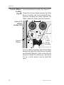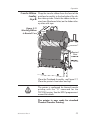
1
Eclipse
LP2344 & TLP2344
User’s Manual
User’s Manual No. 980158-001
©1997 Eltron International Inc.
Rev. A
FOREWORD
This manual provides installation and operation information for the Eclipse LP2344 and
TLP2344 printers, manufactured by Eltron International Incorporated, Simi Valley, California.
TECHNICAL SUPPORT
If for any reason you require product technical support, please contact the Distributor where you
purchased your equipment. If they cannot help you, or at their direction, Eltron Technical Support
can be reached at:
Eltron International Incorporated
41 Moreland Road
Simi Valley, CA. 93065
(800) 344-4003
FAX (805) 579-1808
e-mail: [email protected]
BBS: (805) 579-3445
Eltron International, Europe
Unit 2, Rose Kiln Lane
Reading, Berkshire, RG2 OHP England
+44 (0) 1734 752 024
FAX: +44 (0) 1734 752 005
RETURN MATERIALS AUTHORIZATION
Before returning any equipment to Eltron for in warranty or out of warranty repair, contact Repair
Administration for a Return Materials Authorization (RMA) number. Repack the equipment in the
original packing material and mark the RMA number clearly on the outside. Ship the equipment,
freight prepaid, to the address listed below:
Eltron Repair Administration
41 Moreland Road
Simi Valley, CA. 93065
(805) 579-1800
FAX (805) 579-1808
COPYRIGHT NOTICE
This document contains information proprietary to Eltron International Incorporated. This document and the information contained within is copyrighted by Eltron International Incorporated
and may not be duplicated in full or in part by any person without written approval from Eltron.
While every effort has been made to keep the information contained within current and accurate
as of the date of publication, no guarantee is given or implied that the document is error-free or
that it is accurate with regard to any specification. Eltron reserves the right to make changes, for the
purpose of product improvement, at any time.
TRADEMARKS
Eclipse, LP2344 and TLP2344 are service marks and Eltron is a trademark of Eltron International
Incorporated. Windows & MS-DOS are registered trademarks of Microsoft Corp. All other marks
are trademarks or registered trademarks of their respective holders.
980158-001 Rev.A
iii
WARRANTY INFORMATION
We Need To Hear From You!
To Establish Your Warranty Period And Provide Access To Technical Support,
Send Us Your Product Registration Card Today!
Eltron warrants the mechanism, control electronics and power supply, under normal use and service, to be free from defects in material and workmanship for a period of twelve (12) months from
the date of purchase by the end user. Eltron warrants the printhead, under normal use and service,
to be free from defects in material and workmanship for a period of ninety (90) days from the date
of purchase by the end user. Proof of purchase or product registration is required. If proof of purchase or product registration cannot be established, shipment date to the original buyer (dealer or
distributor) will be be used to establish the warranty period.
Failure to exercise caution to protect the equipment from electrostatic discharge damage, adverse
temperature and humidity conditions or physical abuse may void the warranty. Eltron will, at it’s
option, repair or replace the equipment or any parts which are determined to be defective within
this warranty period, and which are returned to Eltron F.O.B. factory of origin.
The warranty set forth above is exclusive and no other warranty, whether written or oral, is expressed or implied. Eltron specifically disclaims the implied warranties of merchantability and fitness for a particular purpose.
FCC NOTICE:
This equipment has been tested and found to comply with the limits of a Class A digital device,
pursuant to Part 15 of the FCC Rules. These limits are designed to provide reasonable protection
against harmful interference when the equipment is operated in a commercial environment. This
equipment generates, uses and can radiate radio frequency energy and, if not installed and used
in accordance with the instructions, may cause harmful interference to radio communications.
However, there is no guarantee that interference will not occur in a particular installation. Operation of this equipment in a residential area is likely to cause harmful interference in which case the
user will be required to correct the interference at his own expense.
CSA NOTICE:
This equipment does not exceed Class A limits for radio noise emissions for digital apparatus set
out in the Radio Interference Regulation of the Canadian Department of Communications. Operation in a residential area may cause unacceptable interference to radio and TV reception requiring the owner or operator to take whatever steps are necessary to correct the interference.
Cet equipment ne depasse pas les limites de Classe A d’emission de bruits radioelectriques pour
les appareils numerriques tells que perscrites par le Reglement sur le brouillage redioelectrique
etabli par le ministere des Communications du Canada. L’exploitation faite en milieu residentiel
peut entrainer le brouillage des receptions radio et tele, ce qui obligerait le proprietaire ou l’operateur a pendre les dispositions necessaires pour en eliminer les causes.
iv
980158-001 Rev.A
Table Of Contents
Getting Started
Introduction . . . . . .
Unpacking Your Printer
Check List . . . . . . .
Installation . . . . . . .
.
.
.
.
.
.
.
.
.
.
.
.
.
.
.
.
.
.
.
.
.
.
.
.
.
.
.
.
.
.
.
.
.
.
.
.
.
.
.
.
.
.
.
.
.
.
.
.
.
.
.
.
.
.
.
.
.
.
.
.
.
.
.
.
.
.
.
.
.
.
.
.
.
.
.
.
.
.
.
.
1
#
5
7
Operation
Controls & Indicators . . . . . . . . .
Loading Labels or Tags . . . . . . . .
Transfer Ribbon Loading . . . . . . .
Label Variations and the Label Sensor .
AutoSense Gap Sensor Adjustment . .
Cleaning The Print Head . . . . . . .
.
.
.
.
.
.
.
.
.
.
.
.
.
.
.
.
.
.
.
.
.
.
.
.
.
.
.
.
.
.
.
.
.
.
.
.
.
.
.
.
.
.
.
.
.
.
.
.
.
.
.
.
.
.
.
.
.
.
.
.
.
.
.
.
.
.
.
.
.
.
.
.
11
14
23
26
27
28
Appendix A - Trouble Shooting . . . . . . . . . . . . . . . 33
Appendix B - Supplies and Accessories . . . . . . . . . . . 42
Appendix C - Windows Printer Driver . . . . . . . . . . . . 45
980158-001 Rev.A
v
vi
980158-001 Rev.A
Getting Started
1
Getting Started
This section provides information on the
installation of the printer and software.
Introduction The Eltron Eclipse LP2344 (direct thermal)
and Eclipse TLP2344 (thermal transfer) printers are rugged 4" wide low priced industrial
printers. The Eclipse printers designed for industrial environments, such as, receiving
docks, assembly lines, production inspection
points. The Eclipse printers produce high quality on-demand printing of labels and tags, with
or without bar codes, from any DOS™, Windows™or ASCII based compatible computer.
980158-001 Rev.A
1
Getting Started
Features • 4 inches per second (ips) print speed helps
increase productivity & efficiency
• Large 8 inch media roll capacity for production printing reduces the need for frequent
label loading.
• Flash Memory makes firmware updates
seamless.
• Supports over 20 types of bar code symbologies.
• High resolution print head for sharp graphics and text.
2
980158-001 Rev.A
Getting Started
Unpacking Your The printer is shipped in a carton and protecEclipse Printer tive bag. Keep all packing material in case you
need to move or re-ship the printer. Avoid
touching the electrical connectors to prevent
electrostatic discharge damage while setting up
the printer.
CAUTION
CAUTION
980158-001 Rev.A
The discharge of electrostatic energy that
accumulates on the surface of the human body
or other surfaces can damage or destroy the
print head or electronic components used in
this device.
Damage to the printer interface connector
may result from placing the printer on it’s
backside during unpacking or handling.
3
Getting Started
Swing open the printer’s front door. The door
has a magnetic latch for easy access.
Remove the tape retaining the Front Door Insert Cover while holding the Front Door.
Remove Tape
4
980158-001 Rev.A
Getting Started
Check List Your Eclipse printer kit contains the items listed
below.
• An Eclipse LP2344 or TLP2344 printer.
• Create-A-Label Tools software disk with online documentation.
CRE
ATE
-A
Tool -LABE
s
L
• Printer User’s Guide & EPL2 Programming
Manual.
pse
Ecli anual
r' M
Use
r's
L2 e
EP mm al
ra u
og an
M
Pr
980158-001 Rev.A
5
Getting Started
• Ribbon Rewind Core (TLP2344 only).
Rewind Core
(50 2"
mm
)
(10 4"
0m
m)
P
EP
ER MO
TOR
ST
• AC Power Cord
If any items are missing, contact your dealer for
replacement parts.
Label and tag supplies can be purchased directly from ELTRON. Refer to Appendix B for
complete supplies ordering information.
6
980158-001 Rev.A
Getting Started
Installation The following sections will guide you through
the installation of the printer and Create-ALabel Tools software.
Step ➊ Place the printer in a suitable location that alAttach Power lows easy access to all sides of the printer. The
printer should never be operated while resting
on it’s side or upside down.
Figure 1-2
Locating the
Power Switch
Figure 1-1
Power
Switch
Positions
Power Switch
0
OFF
I
ON
Check that the printer’s AC power receptacle
switch is in the OFF (0) position.
The printer should never be operated in a
location where the operator and printer can get
wet. Personal injury could result.
980158-001 Rev.A
7
Getting Started
Attach the AC power cord to the AC power receptacle in the rear of the printer.
Figure 1-3
Printer:
Insert
AC Power
Cord
Attach the AC power cord to a grounded (three
prong) electrical outlet of the proper voltage.
Figure 1-4
Electrical Outlet
Insert
AC Power
Cord
Verify the required voltage on the printer’s
model number label on the backside.
8
980158-001 Rev.A
Getting Started
Step ➋ Parallel Interface
Attach Interface Attach a suitable parallel printer cable from the
Cable computer to the Centronics interface connec-
tor at the back of the printer. Snap the bale lock
to the Centronic’s connector to secure the interface cable to the printer.
Figure 1-5
Parallel
Connector
Serial Interface
Attach a suitable serial printer cable from the
computer to the DB-9 RS-232 Serial interface
connector at the back of the printer. For additional information on serial cable wiring, refer
to Appendix A - Trouble Shooting.
Figure 1-6
Serial
Connector
980158-001 Rev.A
9
Getting Started
Step 3 When the power switch is moved to the ON (1)
Applying Power position, the POWER and ERROR Indicators
should alternately flash indicating that the
printer is out of paper. If the indicators fail to
flash and label stock is not loaded, then refer to
Appendix A - Trouble Shooting.
Step 4 Start your computer. After DOS has loaded, insert the Create-A-Label Tools diskette into
I n s t a l l
your floppy disk drive. From the DOS prompt,
S o f t w a r e
enter B:INSTALL (or A:INSTALL if you placed
the diskette in drive A). Press the Enter key.
Follow the installation instructions on the
screen to install the software.
Refer to Section 2 - Operation, for information
on loading labels and using your printer.
10
980158-001 Rev.A
Operation
2
Operation
This section provides information on the operation of the printer.
Controls & All the printer controls and indicators, except
Indicators for the power switch are on the front panel.
There are two (2) indicator lights and three (3)
control buttons on the front panel.
Indicator
Lights
980158-001 Rev.A
Control
Buttons
11
Operation
The POWER The printer’s POWER SWITCH is located on
SWITCH back panel of the printer. Placing this switch in
the ON (1) position will apply power to the
printer. Place this switch in the OFF (0) position
to remove power when you have finished using your printer. See Figure 1-1 in Section 1.
The POWER The POWER indicator light is green when
Indicator power is on. The POWER indicator light will
flash on and off when the PAUSE is enabled.
POWER & PAUSE
Indicator Light
PAUSE Button
FEED Button
The PAUSE The printing process can be halted by pressing
Button the PAUSE button once. Press the PAUSE
button (again) to resume the print process.
12
980158-001 Rev.A
Operation
The FEED The printer is equipped with a label FEED butButton ton. The printer will feed a single label each
time the FEED button is depressed. This is referred to as a Form Feed. If the FEED button is
pressed and held, the printer will feed a single
label, stop, feed a single label, stop, and so on
until the FEED button is released.
The CANCEL The CANCEL button resets and terminates
Button any print operation in progress.
ERROR
Indicator Light
CANCEL Button
The ERROR The ERROR indicator light is orange when the
Indicator printer detects a hardware error. See Appendix
A for trouble shooting tips.
POWER & ERROR
Indicators
POWER ERROR Condition Report
On Solid
OFF
Power On
Flashing
OFF
Pause
Flashing
OFF
980158-001 Rev.A
Flashing Ribbon or Labels Out
On Solid Hardware Error
13
Operation
Loading Labels Your printer can print on continuous direct
or Tags thermal paper, direct thermal adhesive backed
labels or non-adhesive tags. Loading either labels or tags are easy, (the feed direction of tags
is different).
Refer to Appendix B for a list of supplies available from ELTRON.
CAUTION
DO NOT TOUCH the printhead or the
electronic components under the printhead
assembly.
The discharge of electrostatic energy that
accumulates on the surface of the human body
or other surfaces can damage or destroy the
printhead or electronic components used in
this device.
CAUTION
Adhesive backed labels that DO NOT lay flat
on the backing liner may jam the printer. This
can cause the label to peel off the liner. The
exposed edges may stick to the label guides
and rollers inside the printer. Always use high
quality, Eltron approved labels. Supplies can
be ordered from ELTRON by calling 1(800)
344-4003.
If you should run out of labels while printing,
DO NOT turn the power switch OFF (0) while
reloading or data loss may result. The printer
will automatically resume printing when a new
label roll is loaded.
14
980158-001 Rev.A
Operation
Label Loading Open the top (and right side) cover on the
Step ❶ printer. Slide the Roll Retainer Guide down to
the end of the Label Roll Support.
Figure 2-1
Opening the
Label Roll
Retainer Arm
Roll Retainer Guide
P
EP
ER MO
TOR
ST
Label Roll
Support
980158-001 Rev.A
15
Operation
Label Loading Open the Printhead Assembly by pushing the
Step ➋ release lever to the right, towards the back of
the printer. The printhead assembly will pop
open. Releasing the lever allows it to snap
back.
Figure 2-2
Opening the
Printhead
2"
(50mm)
4"
(100mm)
OR
PER MOT
EP
Push Lever
ST
(50 2"
mm
)
Release Lever
)
OR
PER MOT
EP
(10 4"
0m
m
ST
16
980158-001 Rev.A
Operation
Label Loading Slide the Label Width Adjustment Tab to the
Step ➌ outside stop and rotate up.
Figure 2-3
Label Width
Adjustment Guide
(50 2"
mm
)
Slide
(10 4"
0m
m)
1
P
EP
ER MO
TOR
ST
2
TAB
980158-001 Rev.A
17
Operation
Label Loading Slide a roll of labels onto the Label Roll Guide
Step ➍ and onto Label Roll Support. Labels feed from
the top and towards the front of the printer.
Push the roll to the back of the support and
slide the Label Roll Guide against the label roll
to hold it in place.
Figure 2-4
Loading the
Label Roll
Label Roll
Support & Guide
(5 0 2 "
mm
)
Label Stock
(1 0 4 "
0m
m
)
PER MOT
EP
OR
ST
Label Roll
18
980158-001 Rev.A
Operation
Label Loading Thread the label stock through the Label SenStep ➎ sor Assembly and then between the Platen
(drive roller) and the Printhead.
Figure 2-5
Load The Labels
Printhead
(50 2"
mm
)
(10 4"
0m
m
)
Label
Stock
Label Sensor
Assembly
OR
PER MOT
EP
Platen
T
(50 2"
mm
)
(1 0 4 "
0m
m
)
P
EP
ER MO
TOR
ST
For easy label stock threading, slide half of label into the side of the Label Sensor Assembly
and guide it through the label path.
Bypass Transfer Ribbon Loading
Steps for Direct Thermal Printing operations.
980158-001 Rev.A
19
Operation
Label Loading Rotate the Label Width Adjustment Tab down
Step ❻ and slide it over until it is flush with the label
stock. Check the location of the Through Sensor, refer to Appendix A for adjustment information.
Figure 2-6
Adjusting the
Guide Arm
5 0 m2 "
m)
m)
TOR
P
EP
ER MO
1
20
ST
2
Tab
980158-001 Rev.A
Operation
Label Loading Close the printhead by pressing down on both
Step ❼ sides of the front of the printhead assembly.
Press
Here
Press
Here
Figure 2-7
Closing the
Printhead
980158-001 Rev.A
21
Operation
Label Loading Adjust the label pressure control knob to match
Step ❽ the label stock in use.
Knob
Figure 2-8
Pressure
Control Knob
2"
(50mm)
4"
(100mm)
RM
PPE OT
OR
Label Width
Pressure Control
Knob Settings
2" or Less
2"
Greater Than 2"
4"
Step ❾ Press the Feed button once to verify that the la-
bels advance. Close the printer’s front door
and top (and side) cover.
The printer is configured for direct thermal
printing with the “O” command for the
TLP2344 printer. See the EPL2 programmer's
manual for details.
The printer is now ready for standard Direct Thermal Printing.
22
980158-001 Rev.A
Operation
Transfer Ribbon Slide the appropriate thermal transfer ribbon
Loading roll onto the Ribbon Supply Tube.
Step ❶
Figure 2-9
Installing
Transfer Ribbon
Ribbon Take-up
Tube
(50 2"
mm
)
(10 4"
0m
m)
Ribbon
Supply Tube
Ribbon
Supply Tube
Transfer
Ribbon
980158-001 Rev.A
23
Operation
Transfer Ribbon Open the printhead assembly. See Figure 2-2.
Loading
Step ❷ Thread the transfer ribbon between the Label
Sensor Assembly and the Printhead Bracket.
Continue threading the ribbon between the
Platen (above the labels) and the Printhead.
Figure 2-10
Ribbon
Loading Path
(50 2"
mm
)
Printhead
(10 4"
0m
m)
Transfer
Ribbon
ER MOT
OR
Label
Sensor
Assembly
For easy ribbon threading, slide half of ribbon
between the side of the Label Sensor Assembly
and Printhead Bracket. Guide it from the side
of printer through the ribbon path. See Figure
2-5 for a similar process used to load label
stock.
24
980158-001 Rev.A
Operation
Transfer Ribbon Wrap the transfer ribbon from the front of the
Loading printhead assembly to the backside of the ribStep ❸ bon take-up tube. Attach the ribbon to the rewind core (fiberboard tube) on the ribbon takeup tube with tape.
Figure 2-11
Attaching Ribbon
to Rewind Core
Tape
Rewind
Core
Close the Printhead Assembly, see Figure 2-7.
Close the printer’s front door and top.
The printer is configured for thermal transfer
printing with the “O” command for the
TLP2344 printer. See the EPL2 programmer's
manual for details.
The printer is now ready for standard
Thermal Transfer Printing.
980158-001 Rev.A
25
Operation
Label Variations Your printer is equipped with a sensor capable
and the of detecting the gap between labels while they
Label Sensor are being printed. This feature depends on the
ability of the sensor to “see through” the label
liner between labels.
Due to manufacturing differences in label
stock, the sensor may have difficulty distinguishing the difference between the labels and
the liner. When this occurs, the printer ERROR
Indicator (AMBER/ORANGE) will switch on.
The printer may stop a label in the middle. If
this condition occurs, the AutoSense feature
should be activated to adjust the sensitivity of
the sensor. Also check to insure the that the
command line/programs defined label length
matches the label in use.
Windows Users!
Use the Windows Control Panel for Printers to
select the label size that matches the labels
loaded in the printer. See Appendix C.
26
980158-001 Rev.A
Operation
AutoSense Load labels into the printer. Do not use the
Gap Sensor auto-dispense/peeler mode for this procedure.
Adjustment Press and hold the PAUSE and CANCEL control buttons with the power on. Release the
CANCEL button first and then release the
PAUSE button.
The printer will start feeding labels automatically. The printer will automatically adjust the
gap sensor and measure the label length.
After the sensor has been adjusted, the printer
will enter DUMP mode and print the standard
information label.
Press the FEED button once to switch the
printer back to normal operation. If the Error
indicator light (continues) to glow AMBER/ORANGE, refer to Appendix A for troubleshooting information.
980158-001 Rev.A
27
Operation
Cleaning The As you use your printer, the printhead may bePrint Head come dirty resulting in poor print quality.
Whenever new labels are loaded into the
printer, the print head should be cleaned with a
Cleaning Pen.
Cleaning Pens (P/N 800105-001) are available
directly from ELTRON. Supplies can be ordered from ELTRON by calling 1(800) 3444003.
Step ➊ Open the printhead assembly and remove any
labels loaded in the printer, see Figure 2-2.
Hand rewind the labels back onto the roll.
Figure 2-12
Locating the
Printhead
Printhead
Step ➋ Gently rub the Cleaning Pen across the amber
area of the printhead.
Figure 2-13
Printhead
Cleaning
Allow the print head to dry for 1 minute before
reloading the labels.
28
980158-001 Rev.A
Appendix A This section addresses the most common isTrouble Shooting sues user’s may face with operation and configuration of the printer.
The first trouble shooting reference source is
the Common Problems Trouble Shooting table
on the following page.
Eltron International also provides a variety of
information and user support services:
• Internet:
Web Address: http://www.eltron.com
e-mail: [email protected]
ftp: //ftp.eltron.com
• BBS: (805) 579-3445
The BBS supports data rates up to 28.8 BPS
with No Parity, 8 data bits, and 1 stop bit
(n,8,1). Communications software should
have an ANSI Terminal Mode (not MS Windows Terminal) such as Q-Modem.
• CompuServe e-mail: 102251,1164
• Customer Service: (800) 344-4003
To order printer supplies and accessories.
Eltron accepts Mastercard and Visa for
phone orders.
• Technical Support: (800) 344-4003
For your assistance and support with Eltron
printers and software.
980158-001 Rev.A
29
Common Printing Problems
Trouble Shooting Guide
Problem
Solution or Reason
POWER indicator does not
light GREEN when power 1. Check power connections from the
switch is turned to the ON (1)
printer to the outlet.
position.
1. Verify that the labels are the correct
With the POWER indicator
type.
light GREEN, the printer ap- 2. Check that the roll is loaded with the dipears to be working, but
rect thermal side facing up.
nothing is printed.
3. Check that the transfer ribbon is correctly routed and has the ink side out.
Printing is faded or poor
quality.
1. Clean the print head with cleaning pen.
2. Adjust print speed/darkness in software
or with programming.
3. TLP2344 - Verify that the “O”command
parameters match the printing mode; direct or thermal transfer printing.
Printing stops and the
ERROR indicator lights
AMBER/ORANGE.
1. Possible problem with label gap sensor.
Perform AutoSense adjustment.
2. Possible problem with label stock. Gap
between the bottom of a label and the
top of the next label should be at least
1/16". For tags, see Figure A-2. Use
onlyEltron approved labels and tags.
3. Possible label jam.
4. Check that the transfer ribbon and label
stock are routed correctly.
5. TLP2344 - Ensure that the printer mode
matches the method of printing; direct
or thermal transfer printing.
6. Possible software problem. Check the
printer memory configuration. Refer to
the EPL2 Programming manual for the
correct data syntax.
30
980158-001 Rev.A
Problem
Solution or Reason
Printer cuts (melts) through
1. Verify that the printing heat is set to it’s
the transfer ribbon. The ribrecommended level. See Printer Media
bon is advancing at the same
Temperature Settings, Appendix A.
rate as the label stock.
GREEN and AMBER are
alternately flashing.
980158-001 Rev.A
1. Check for Out-of-Media condition or
missing labels in the middle of a roll.
2. Check that the ribbon and label stock
are correctly routed.
3. Ensure that print mode program settings
match the print mode.
31
Serial Interface The printer’s serial port is configured with the
Communication “Y” command for the printer. See the EPL2
Configuration programmer's manual for details.
The printer’s serial port default configuration
is: 9600 baud
8 bit data
1 stop bit
No parity
Serial Interface The figure below displays the cable wiring reCable Wiring quired to use the printer’s serial interface
Host
N/C
RxD
TxD
DTR
GND
DSR
RTS
CTS
RI
DB-9
Pin #
1
2
3
4
5
6
7
8
9
Printer
DB-9
Pin #
1
2
3
4
5
6
7
8
9
+5 Volts*
TxD
RxD
N/C
GND
RDY
N/C
RDY
N/C
Female DB-9 to Male DB-9
Host
N/C
RxD
TxD
DTR
GND
DSR
RTS
CTS
RI
DB-25
Pin #
8
3
2
20
7
6
4
5
22
Printer
DB-9
Pin #
1
2
3
4
5
6
7
8
9
+5 Volts*
TxD
RxD
N/C
GND
RDY
N/C
RDY
N/C
Female DB-25 to Male DB-9
*+5 volts at 150 mA for external device (e.g. KDU or scanner)
32
980158-001 Rev.A
Printer Tag The printer uses a moveable sensor to detect
Sense Through index holes/notches in tag stock. The sensor
Hole Position position is indicated by the green arrow at the
front of the label guide that is visible with the
printhead open. The sensor can be moved by
squeezing the two locking tabs, located under
the label guide, and sliding the sensor in or out.
For proper sensing, ensure that the sensor is
aligned with the center portion of the index
hole/notch.
The following dimensions show the required
position of the Sense-Through (“Notch”) hole
on tag stock for the printer.
C
min.
Figure C-1
Tag Position
Sensing Layout
max.
B
A
Tag Tearaway
Inside Edge
of Tag Stock
.314 Nominal Sensor Location
980158-001 Rev.A
Dimension
Min.
Max.
Nominal
A
.236"
None
.512"
B
.079"
.512"
.118"
C
.098"
1.520"
N/A
33
Printer Media This table describes the recommended ribbon,
Temperature media, and heat settings for the printer.
Settings
Ribbon
Part No.
Ribbon
Type
Heat
Setting
Media
Type
Media
Part No.
800010
Wax
3
Paper
800622 / 800640
800011
General
Purpose
Resin
5
2
2
Paper
800622 / 800640
White Polyester 800822 / 800840
Silver Polyester 800922 / 800940
800005
Resin
10
10
White Polyester 800822 / 800840
Silver Polyester 800922 / 800940
Printer Features The Eclipse LP2344 and TLP2344 printers are
and Options part of Eltron’s heavy duty line of industrial
printers. The Eclipse has a 4 inch print width,
203 dpi print resolution and up to 256KB user
configurable memory. It prints in both direct
thermal and thermal transfer mode. The
Eclipse prints up to 4 inches per second.
User Features:
• Performs self test and prints out it’s configuration
• Automatic label sensor adjustment
• Easy to use command language
• Label inversion
• Auto label edge detection
• Auto increment and decrement for numeric
and bar code fields
• Line and box drawing features
• Repeat label feature
34
980158-001 Rev.A
Printing:
• Direct thermal and thermal transfer printing
• Selectable constant print speeds of 2 or 4
inches per second (ips)
• 203 dots per inch (8 dots/mm) print resolution
• IPHC (Intelligent Print Head Control) for
high quality printing in all orientations
• Maximum print width: 4.09 inch (104mm)
Print Modes:
• Three print modes are included as standard:
• Batch-printing one or more labels with the
labels left on the backing paper
Bar Codes
Standard (One Dimensional) Bar Codes:
• Code 39
• Code 93
• Code 128 UCC
• Code 128, Subsets A, B, and C.
• Codabar
• Interleaved 2 of 5
• UPC-A, UPC-E, 2 & 5 digit add-on
• UPC shipping container code
• EAN-13, EAN-8, 2 & 5 digit add-on
• POSTNET
• German POSTNET
980158-001 Rev.A
35
Bar Codes
Two Dimensional Bar Codes (Optional):
• PDF417 (TLP \-2046/417 only)
• Maxicode
• Bar codes can be printed in four directions"
0 , 90, 180, and 270 degrees
• Bar code modules (“X” dimension): .005"
(.12mm) to .050" (1.27mm)
Standard Fonts:
• Five alpha-numeric fonts from .049 inches
(1.25mm) to .23 inches (6.0mm) high
• All fonts are expandable vertically and horizontally up to 8x
• Fonts can be printed in four directions: 0 ,
90, 180 , and 270 degrees
• International character sets standard
• Any font or PCX graphic field can be downloaded from CREATE-A-LABEL
Media Sensing:
• “See-through” sensor for die-cut labels and
tags
• Reflective sensor for use with black stripe
marks
• Programmable top of form
Media Specifications
• Type: Roll-fed, die-cut, continuous or fanfold labels, tags or tickets
• Materials: plain paper thermal transfer or
thermal sensitive papers
• Maximum media width: 4.5" (114mm)
36
980158-001 Rev.A
• Minimum media width: 1.12" (28.6mm)
• Maximum media length: 6.0" (152mm)
(with standard memory)
• Minimum media length: 0.38" (9.7mm)
• Thickness (including liner): 0.003" to 0.010"
(.076mm to .250mm)
• Supply roll capacity: 8" (203mm) maximum
O.D. (outer diameter) and 3" (76.2mm)
minimum I.D. (inner diameter)
• Fanfold stock can be fed through a slot in the
rear panel of printer
Ribbons:
• Standard widths: 1.3" (33mm), 2.5"
(64mm), 3.3" (84mm), 4.3" (109mm)
• Length: 14,270" (362mm) and lengths for a
1:2 ratio of labels vs. ribbons
• Other widths available on a custom order
basis
Mechanical:
• Width: 9.3" (236mm)
• Depth: 15.75" (400mm)
• Height: 12.2" (310mm)
• Weight: 35 lb.. (15.9kg)
Electrical:
• Power 110/220 VAC +10% single phase
60/50 Hz at 5 amps maximum
• Built to UL, CSA and TUV-GS safety standards and FCC Class A, VDE Class B emissions standards
980158-001 Rev.A
37
Environmental:
• Operating Temperature: 40 degrees F to
105 degrees F (5 degrees C to 40 degrees C)
• Storage Temperature: -4 degrees F to 158
degrees F (-40 degrees C to 70 degrees C)
• Humidity: 10% to 95% non-condensing
• Ventilation: free air
Options:
• RS-422 Interface
• Standard memory expands up to 384K
Flash memory expansion up to 8 Mbytes
• Media Length up to 18" (560mm)
• Create-A-Label III software
• Windows Printer Driver
• Used with Eltron’s KDU (Keyboard display
unit) for a stand alone printing solution
• Media Cutter
• International Characters
• Twinax AS/400 protocol converter
38
980158-001 Rev.A
Appendix B Supplies and Accessories can be ordered from
Supplies and your Eltron dealer where you purchased your
Accessories printer or by calling ELTRON at:
1(800) 344-4003
Accessories Accessories available for the Eclipse printer are
listed below. Always refer to the ELTRON part
number when placing an order.
Description
Parallel Interface Cable, 6’
Parallel Interface Cable, 10’
Serial Interface Cable, 6’ (DB-9 to DB-9)
Serial Interface Cable, 10’ (DB-9 to DB-9)
Serial Interface Cable, 6’ (DB-25 to DB-9)
Automatic Label & Tag Cutter
Label & Tag Stacker (used with Automatic Cutter option)
KDU (Keyboard Display Unit)
Part Number
300016-006
300016-010
300017-006
300017-010
300018-006
103132-001
103153-001
120180-001
Windows Printer Driver
Create-A-Label TOOLS for DOS
Create-A-Label 3 for DOS
105501-003
105505-001
105506-001
User’s Manual (this Manual)
Programmers Manual
980158-001
980009-001
980158-001 Rev.A
39
Direct Thermal
Thermal Transfer
40
980158-001 Rev.A
Typical Applications
Shipping
Inventory Tracking
Shipping
Inventory Tracking
Product Labeling
Compliance Labeling
Features
Low cost
Ease of use
Low Environmental Durability
Limited Label Life
Will fade and/or discolor when
exposed to heat, sunlight, and
chemicals.
Lowest cost thermal transfer
combination
Most commonly used
Low environmental durability
Low abrasion resistance
Longer life than direct thermal
Media (Stock) Ribbon
Not Used
Wax
Paper Label
Tag
Synthetic Label
Paper Label
Tag
980158-001 Rev.A
41
Thermal Transfer
High temperature environments
Medical applications
Outdoor environments
Environments with chemicals
Compliance labeling
Hard Resin
Synthetic Label
High environmental durability
High physical durability
Excellent aesthetic appearance
Most expensive label/tag
combination
Retail applications where labels are
handled
Excellent for most applications
Compliance Labeling
Typical Applications
General
Better environmental durability.
Purpose Resin Better abrasion resistance than
wax
More expensive than wax
Good aesthetic appearance
Features
Paper Label
Tag
Synthetic Label
Media (Stock) Ribbon
42
980158-001 Rev.A
Appendix C
Using The
Windows Printer
Driver
The Windows printer driver provides control of
several printer features when printing from
Windows software applications. These features
are accessed through the “Settings / Printers”
control panel on the Windows 95 Start menu.
Paper (Label) Size Before creating a label, the paper size for the
currently loaded labels must be selected in the
control panel.
Setting the proper label size allows the driver to
provide accurate printing limits and margin information to Windows applications.
Media Choice The print speed can be adjusted to compensate
Print Speed for manufacturing differences in label stock.
Selecting a slower print speed can improve the
appearance of lines and text on some label
stocks. When printing large labels or labels with
a lot of information near the right edge, a
slower print speed will avoid pauses while
printing caused by buffer under-run. To access
this menu, select the Paper tab from the printer
setup control panel.
980158-001 Rev.A
43
Print Quality, The print darkness or density can be changed
Print Density by using the Print Quality option. If print looks
faded when printing at high speed, select a
higher darkness number for the Print Quality
setting. If horizontal lines seem to run together,
select a lower darkness number.
To access this menu, select the Device Options
tab from the printer setup control panel.
HINT
44
Print density is also affected by print speed.
Changing both Print Speed and Density may
be required to achieve the desired results.
980158-001 Rev.A
Eltron International, Inc.
41 Moreland Road
Simi Valley, CA 93065