1
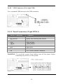
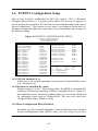
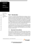
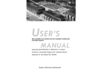
S7-MVP3 Motherboard User’s Manual Product Name: S7-MVP3 Manual Revision: English,1.20 May 13, 1998 Release Date: Table of Contents Chapter 1. Introduction 1.1 1.2 1.3 1.4 Product Overview… … … … … … … ..… … … … … .. Content… … … … … … … … … … … … … … … … … . Specifications… … … … … … … … … … … ..… … … . System Board Layout… … … … … … … … … .… .… . 6 6 7 9 Chapter 2. Hardware Setup 2.1 Installation Procedure… … … … … … ..… … ...… … . 2.1.1 Jumper Settings… … … … … … … … ..… … … 2.1.2 Clearing the CMOS… … … … … ...… … .… … 2.1.3 CPU Voltage Setting… … … … ...… … … … .. 2.1.4 CPU BF Ratio Selection… … .… … … … ..… . 2.1.5 CPU External Clock Selection… … … … … ... 2.1.6 CPU-PCI Clock Selection… … … … … … … . 10 10 11 12 13 13 14 2.2 14 Installation of CPU… … … … … … … … … … … .… . 2.3 Installation of Memory… … .… … … .… … … … .… . 15 2.3.1 Installation of 168-pin DIMM… … … … … … 15 2.3.2 Removal of 168-pin DIMM… … … … … … ... 15 2.3.3 Memory Configuration… … … … .… .… … … . 16 2.4 I/O Connections/Panel Connections… … … .… … . 16 2.4.1 ATX Power Connector… … … … … … … … ... 17 2.4.2 Power, Chassis & CPU Fan Connectors...… .17 2.4.3 IrDA Connector… … … … … … … … … … .… .18 2.4.4 Floppy Disk Drive Connector… … … … … … 18 2.4.5 Primary/Secondary IDE Connector… ..… … .19 2.4.6 PS/2 Mouse Port… … … … … … … … … ...… . 19 2.4.7 Keyboard Connector… … … .… … … … … … . 20 2.4.8 Serial Port… … … … … … … .… … … … … .… . 20 2.4.9 Printer Port… … … … … … … .… … … … … … 20 2.4.10 USB Connectors… … … … … .… … … ....… … 21 2.4.11 Panel Connection… … … … … … .… ...… … ... 21 2 Chapter 3. BIOS Setup 3.1 3.2 3.3 3.4 3.5 3.6 3.7 3.8 3.9 3.10 3.11 3.12 Main Menu… … … ...… … … … .… … ..… … … … … Standard CMOS Setup..… … … … .… … … … .… … . BIOS Features Setup… … … … … … ..… … … … … . Chipset Features Setup… … … … … ..… … … ..… … Power Management Setup… … … … ..… … … … … . PNP/PCI Configuration Setup… … … .… … … … … Integrated Peripherals… … … … … … … … … … … .. Load BIOS Defaults… … … … … … … … … … … … Load Setup Defaults… … … … … … … … … … … … Supervisor/User Password… … … … … .… … … .… . IDE HDD Auto Detection… … … … … … … … … ... Exit CMOS Setup Utility… … … … … … … … … … . 3 24 26 29 33 36 40 43 46 46 46 47 47 Chapter 1. Introduction 1.1 Product Overview Thank you for purchasing the S7-MVP3 motherboard. This motherboard utilizes VIA's latest technology, namely VT82CMVP chipset. We have conducted a motherboard compatibility test with a variety of hardware and software, such as CPUs, memory, display card, CD ROM, Novell, MS Office....etc. We set high standards on our quality control, with absolute confidence, we believe this product is the wisest choice. This manual is composed of two sections. The first section explains the proper procedure to setup the S7-MVP3 motherboard, and the second section provides information on how to setup the BIOS. Features: ¡ · Support Desktop Management Interface (DMI) through BIOS. ¡ · Support NCR SCSI BIOS. ¡ · Support Accelerated Graphics Port (AGP) cards for high performance. ¡ · Modem Remote Ring On. ¡ · RTC Wake Up Alarm: Program the date/time to wake up your system. ¡ · CPU Thermal Protection: Warning when the CPU temperature is too high. ¡ · CPU & System Voltage Monitoring. ¡ · CPU, Chassis & Power supply fan speed monitoring. ¡ · Support Advanced Configuration Power Interface (ACPI). ¡ · BIOS Green feature function, and “Plug & Play” Flash ROM. 1.2 Content The S7-MVP3 motherboard contains the following items: - The S7-MVP3 Motherboard - One IDE Ribbon Cable - One Floppy Ribbon Cable - One Bus Master Driver - User's Manual & Quick Installation Chart 4 1.3 Specification CPU¡ G -Supports 75-333 MHz Pentium Processors ¡ ] P54C¡^ , and Pentium Processors with MMX technology ¡ ] P55C¡^ -Supports AMD K5/K6/K6-3D serial CPUs -Supports Cyrix/IBM 6x86/6x86L/6x86MX serial CPUs Chipset¡ G -VIA MVP3 Chipset VT82CMVP & VT82C586B System Clock¡ G-Supports 60/66/75/83/90/100 MHz Host clock -Supports 8 MHz AT bus speed DIMM¡ G -Supports 66MHz or faster 3.3V in 3 168-pin banks, 3 168 -pin 64-bit DIMM sockets using 8/16/32/64/128 MB memory -Supports up to a maximum of 384 MB system memory -Optional bank-by-bank ECC or EC for DRAM integrity L2 Cache¡ G -Onboard 512KB/1MB Pipeline Burst SRAM IDE¡ G -Dual channel PIO and PCI Bus Master IDE ports support up to 4 EIDE devices for HDD or CD-ROM -Supports PIO Mode 4 with data transfer rate up to 22 MB/ Sec -Supports Ultra DMA 33 ¡ ]UDMA¡ ^with data transfer rate up to 33 MB/Sec -Supports multi-word DMA Mode 2 transfer I/O Devices¡ G -One FDD control port supports two of the 5.25" or 3.5" floppy drives up to 2.88 MB. -Two high-speed 16550 UART compatible serial ports -One parallel ports with ECP/ EPP compatibility. -One PS/2 mouse connector (mini Din) -One PS/2 Keyboard connector (mini Din) IR Port¡ G -One HPSIR/ASKIR compatible IrDA interface port. ¡ ]Cable optional¡ ^ 5 USB Ports¡ G -Two Universal Serial Bus ¡ ]USB¡ ^ports support up to 127 peripheral devices. -Universal Host Controller Interface V.1.1 compatible -Supports 1.5-12MB/S transfer rates -Supports legacy keyboard and mouse BIOS¡ G -Award BIOS V.4.51 with built-in Anti-Virus, DMI support, and green function ¡ ] Plug-and-Play BIOS¡ ^ -Supports NCR SCSI BIOS -Supports CD-ROM, SCSI, and LS120/ZIP boot up -Supports Multiple Boot Up Power¡ G Management -Supports ACPI & APM -Supports ring remote power-on function -Supports software power off function -Supports RTC Alarm. -ATX power button Expansion¡ G -One 64-bit AGP expansion slot Slots -Five 32-bit PCI expansion slots -Two 16-bit ISA expansion slots -Supports latest PCI 2.1 standard Operating¡ G -Supports Windows 95, Windows NT, MS-DOS V6.22, System OS2, Novell, Unix, SCO UNIX..... Board Size¡ G -305mm x 200mm ATX form factor Other¡ G -On-board PWM switching power supply for CPU core voltage -Auto disable clock not used to reduce EMI -Supports CPU & system temperatures, system voltages & fan speeds monitoring 6 1.4 System Board Layout 7 Chapter 2. Hardware Setup 2.1 Installation Procedure 1. Jumper setting ¡ ]BIOS and CPU¡ ^ 2. Installation of CPU 3. Installation of Memory 4. I/O Connections & Panel Connections 2.1.1 Jumper Settings In this manual , ¡ ]1-2¡ ^represents the first and second pins of the jumper. ¡ ]2-3¡ ^represents the second and third pins of the jumper, and so on. "ON" means put on the jumper cap and "OFF" means remove the jumper cap. On the motherboard, you will see three sets of jumpers with different color jumper caps: Yellow Jumper Caps¡ S G ets the Function and of Flash CMOS JVBAT1, JAGP1~3 Red Jumper Caps¡ GSets the voltage of CPU JPW1 Green Jumper Caps¡ S G ets the type and speed of CPU F1~3, JP1~3 WARNING: Electronic parts are Static sensitive. To prevent damage to the computer and its parts please take the following measures. -Work on a surface such as concrete, linoleum or hard wood floor. -Ground your self with either a properly installed grounding strap or by touching a major electrical appliance long enough to discharge the static. 8 2.1.2 Clearing the CMOS¡ ]Yellow Jumper Cap¡ ^ JVBAT1¡ G CMOS Function Selection 1-2 ON¡ N G ormal Operation¡ ]Default Setting¡ ^ 2-3 ON¡ GClear CMOS setting How to Remove the CMOS Setting ¡ 1 ]¡ ^Turn off the power. ¡ ] 2¡ ^Remove ATX power cable from connector CN1. ¡ ] 3¡ ^Remove Yellow Jumper Cap from JVBAT1¡ ] 1-2¡ ^ and put on JVBAT1¡ ]2-3¡ ^to remove the CMOS setting. ¡ ] 4¡ ^Remove Yellow Jumper Cap from JVBAT1¡ ] 2-3¡ ^ and put on JVBAT1¡ ]1-2¡ ^. ¡ ] 5¡ ^Connect ATX power cable back to connector CN1. ¡ ] 6¡ ^Turn on the power. ¡ ] 7¡ ^While the system reboots, press <DEL> key to set the BIOS setup. 9 2.1.3 CPU Voltage Selection ¡ ]Red Jumper Caps¡ ^ Before the use of this motherboard, make sure all jumpers are set correctly. The wrong setting might damage the CPU and the motherboard. CPU Voltage may vary. Check with CPU manufacturer for it's correct voltage. CPU CPU TYPE CPU JPW1 Brand Voltage 3-4, 5-6, 7-8, 9-10 AMD K6-266 2.0V 1-2 AMD K6-3D 300 2.1~2.25V 7-8 Intel/Cyrix P55C-MMX/6x86L 2.8V 1-2, 7-8 AMD/Cyrix K6-166/200, 6x86MX 2.9V 5-6, 7-8 AMD K6-233 3.2V 1-2, 5-6, 7-8 Intel P54C 3.3V 3-4, 5-6, 7-8 Intel P54C 3.4V 1-2, 3-4, 5-6, 7-8 AMD/Cyrix K5/6x86 3.5V 2.8V is the default setting (this setting is for Intel P55C CPUs) 10 2.1.4 CPU BF Ratio Selection (Green Jumper Caps) BUS/CORE 1.5x/3.5x 2.0x 2.5x 3.0x 4.0x 4.5x 5.0x 5.5x JP3 1-2 1-2 2-3 2-3 1-2 2-3 2-3 1-2 JP2 1-2 2-3 2-3 1-2 2-3 2-3 1-2 1-2 JP1 1-2 1-2 1-2 1-2 2-3 2-3 2-3 2-3 3.0x is the default setting¡ ]this setting is for Intel P55C-200 CPU¡ ^ 2.1.5 CPU External Clock Selection (Green Jumper Caps) Clock 60MHz 66MHz 68.5MHz 75MHz 83MHz 90MHz 100MHz 112MHz F3 1-2 1-2 2-3 1-2 1-2 2-3 2-3 2-3 F2 1-2 1-2 2-3 2-3 2-3 1-2 1-2 2-3 F1 2-3 1-2 2-3 1-2 2-3 2-3 1-2 1-2 66MHz is the default setting¡ ]this setting is for Intel P55C-200 CPU¡ ^ 11 2.1.6 CPU-PCI Clock Selection (Yellow Jumper Caps) CPU CLOCK 60~75 MHz 83~112 MHz JAGP3 2-3 1-2 JAGP2 2-3 1-2 JAGP1 2-3 2-3 60~75 MHz is the default setting¡ ]this setting is for Intel P55C-200 CPU¡^ 2.2 Installation of CPU Before installing CPU, make sure the power is off. Locate the white color level bar on the ZIF socket. Push level bar away from the socket and pull upward 90 degrees. Insert the CPU into the socket. Make sure the notch of the CPU corresponds with the white dot on the ZIF socket (the corner without pin socket). Do not push in the CPU. Make sure all pins are aligned with the CPU socket. Close the level bar. 12 2.3 Installation of Memory S7-MVP3 motherboard has 3x168-pin 64-bit Dual Inline Memory Module ¡ ] DIMM¡ ^ sockets divided into 3 banks. You can install 3.3V Extended Data Output¡ ] EDO¡ ^or Unbuffered Synchronous DRAM¡ ] SDRAM¡ ^ memory. This will increase the system reliability. 2.3.1 Installation of 168-pin DIMM 1. Before inserting the DIMM, make sure the pin1 of the DIMM matches with the pin1 on the DIMM socket. 2. Insert DIMM into the DIMM sockets at a 90-degree angle and press down. 2.3.2 Removal of 168-pin DIMM 1. Press the holding clips on both sides of the socket outward to release the DIMM. 2. Gently pull the DIMM out of the socket. 13 2.3.3 Memory Configuration There is no jumper setting required for the memory size or type. It is automatically detected by the system BIOS, and the total memory size is to add them together. DIMM Socket DIMM1 DIMM2 DIMM3 DIMM Modules EDO/SDRAM 8, 16, 32, 64, 128MB EDO/SDRAM 8, 16, 32, 64, 128MB EDO/SDRAM 8, 16, 32, 64, 128MB The S7-MVP3 Motherboard has been tested with the memory listed below. Size/Type Vendor Model Side Chip SPD Count 16MB/SDRAM Fujitsu 811171622A-100FN x2 8 No 16MB/SDRAM Hitachi HM5216805TT10 x1 8 No 16MB/SDRAM HY57V168010BTC-10 X1 8 Yes 32MB/SDRAM Mitsubishi M5M4V16S30BTP-10 x2 16 No 32MB/SDRAM Mitsubishi M5M4V16S30BTP-10 x2 16 Yes 32MB/SDRAM OKI M56V16800D-10 X2 16 No 32MB/SDRAM HY57V168010BTC-10 x2 16 Yes 32MB/SDRAM TI TMS626812DGE-12A x2 16 No 32MB/SDRAM Micronic MT48LC2M8A1-12 x2 16 No 64MB/EDO Panasonic MN41V17400CTT-06 X2 32 No 128MB/SDRAM NEC D4564841G5-A10-9JF x2 16 No 2.4 I/O Connections/Panel Connections I/O Connections CN1 JIR1, IR FDD1 IDE1, 2 PS2, J2 KB, J1 COM1,2 LPT1 JUSB1 ATX Power Connector IrDA Connector ( Cable optional ) Floppy Disk Drive Connector Primary/ Secondary IDE Connectors PS/2 Mouse Port Keyboard Connector Serial Ports 1 & 2 Printer Port USB Connector 14 2.4.1 ATX Power Connector (20-pin CN1) Make sure that the power supply is off before connecting or disconnecting the power cable. 2.4.2 Power, Chassis & CPU Fan Connectors (3-pin FAN) Connect the fan’s plug to the board taking into consideration the polarity of the connector. 15 2.4.3 IrDA Connector (5-pin JIR1 & IR) This connector supports the optional wireless transmitting and receiving infrared module, with this module and application software such as Laplink or Win95 Direct Cable Connection, user can transfer files to or from their laptops, notebooks, PDA, PCs and printers. The connector supports HPSIR (115.2Kbps, 2 meters) and ASK-IR (56Kbps). Install infrared module onto IrDA connector and configure the setting through ‘UART 2 Mode’ in Integrated Peripherals to select. whether UART is directed for use with COM2 or IrDA. 2.4.4 Floppy Disk Drive Connector (34-pin FDD1) This connector supports the provided floppy disk drive ribbon cable. Orient the red stripe to pin 1 16 2.4.5 Primary/Secondary IDE Connector (Two 40-pin IDE) These connectors support the provided IDE hard disk ribbon cable. Connect your first IDE hard disk to master mode of the primary channel. If you have second IDE device to install in your system, connect it as slave mode on the same channel, and the third and fourth device can be connected on secondary channel as master and slave mode respectively. 2.4.6 PS/2 Mouse Port (6-pin Mini-Din PS2 & 4-pin J2) The system will direct IRQ12 to the PS/2 mouse. 17 2.4.7 Keyboard Connector (6-pin Mini-Din KB & 4-pin J1) This connection is for a standard keyboard using a PS/2 plug. You may use a Din to Mini-Din adapter on standard AT keyboards. 2.4.8 Serial Port (Two 9-pin D-type COM) 2.4.9 Printer Port (25-pin D-type LPT1) You can enable the parallel port and choose the IRQ through the “Onboard Parallel Port” setting in Integrated Peripherals of the COMS SETUP UTILITY. 18 2.4.10 USB Connectors (Two 4-pin USB) You can attach USB devices to the USB connector. 2.4.11 Panel Connection (32-pin FPNL1) FPNL1 Connector TBLED KEYLOCK SPK SMI TRSW RST IDE IR PR Function Turbo LED Power LED and Keylock Switch Speaker Sleep Switch Turbo Switch Reset Switch HDD LED IrDA Connector ATX Power Switch Connector WARNING: To avoid the system from failing, turn off the power before connecting any devices to the system. 19 Chapter 3. BIOS Setup Starting Setup The Award BIOS is immediately activated when you first power on the computer. The BIOS reads the system information contained in the CMOS and begins the process of checking out the system and configuring it. When it finishes, the BIOS will seek an operating system on one of the disks and then launch and turn control over to the operating system. While the BIOS is in control, the Setup program can be activated in one of two ways: By pressing ¡ Õ DEL¡ Ö key immediately after you turn on the system, or by pressing the <Del> key when the following message "Press DEL to enter SETUP" should appear in the lower left hand corner of your screen. If the message disappears before you respond and you still wish to enter Setup, restart the system to try again by turning it OFF then ON or pressing the "RESET" button on the system case. You may also restart by simultaneously pressing <Ctrl>, <Alt>, and <Delete> keys. If you do not press the keys at the correct time and the system does not boot, an error message will be displayed and you will again be asked to... PRESS F1 TO CONTINUE, DEL TO ENTER SETUP Using Setup In general, you use the arrow keys to highlight items, press <Enter> to select, use the PageUp and PageDown keys to change entries, press <F1> for help and press <Esc> to quit. The following table provides more detail about how to navigate in the Setup program using the keyboard. Getting Help Press F1 to pop up a small help window that describes the appropriate keys to use and the possible selections for the highlighted item. To exit the Help Window press <Esc> or the F1 key again. 20 Up arrow Down arrow Left arrow Right arrow Esc key PgUp key PgDn key + key - key F1 key (Shift)F2 key F3 key F4 key F5 key F6 key F7 key F8 key F9 key F10 key Move to previous item Move to next item Move to the item in the left hand Move to the item in the right hand Main Menu -- Quit and not save changes into CMOS Status Page Setup Menu and Option Page Setup Menu -- Exit current page and return to Main Menu Increase the numeric value or make changes Decrease the numeric value or make changes Increase the numeric value or make changes Decrease the numeric value or make changes General help, only for Status Page Setup Menu and Option Page Setup Menu Change color from total 16 colors. F2 to select color forward, (Shift) F2 to select color backward Calendar, only for Status Page Setup Menu Reserved Restore the previous CMOS value from CMOS, only for Option Page Setup Menu Load the default CMOS value from BIOS default table, only for Option Page Setup Menu Load the default Reserved Reserved Save all the CMOS changes, only for Main Menu 21 3.1 Main Menu Once you enter the Award BIOS CMOS Setup Utility, the Main Menu will appear on the screen¡ ]Figure 3-1¡^. The Main Menu allows you to select from several setup functions and two exit choices. Use the arrow keys to select among the items and press <Enter> to accept and enter the sub-menu. Figure 3-1. CMOS Setup Utility Main Screen ROM PCI/ISA BIOS (2A5LEV5B) CMOS SETUP UTILITY AWARD SOFTWARE, INC. STANDARD CMOS SETUP BIOS FEATURES SETUP CHIPSET FEATURES SETUP POWER MANAGEMENT SETUP PNP / PCI CONFIGURATION LOAD BIOS DEFAULTS LOAD SETUP DEFAULTS INTEGRATED PERIPHERALS SUPERVISOR PASSWORD USER PASSWORD IDE HDD AUTO DETECTION SAVE & EXIT SETUP EXIT WITHOUT SAVING ↑ ↓ → ← : Select Item (Shift) F2 : Change Color Esc : Quit F10 : Save & Exit Setup Time, Date, Hard Disk Type... 3.1.1 STANDARD CMOS SETUP This setup page includes all the items in a standard, AT-compatible BIOS. 3.1.2 BIOS FEATURES SETUP This setup page includes all the items of Award special enhanced features. 3.1.3 CHIPSET FEATURES SETUP This setup page includes all the items of chipset special features. 3.1.4 POWER MANAGEMENT SETUP This setup page includes all the items of Power Management. 22 3.1.5 PNP / PCI CONFIGURATION This setup page includes all the items of PNP / PCI function. 3.1.6 LOAD BIOS DEFAULTS The BIOS defaults have been set by the manufacturer and represent settings which provide the minimum requirements for your system to operate. 3.1.7 LOAD SETUP DEFAULTS The chipset defaults are settings which provide for maximum system performance. While Award has designed the custom BIOS to maximize performance, the manufacturer has the right to change these defaults to meet their needs. 3.1.8 INTEGRATED PERIPHERALS This section page includes all the items of Programmed Input / Output features. IDE hard drive and 3.1.9 SUPER / USER PASSWORD SETTING Change, set, or disable password. It allows you to limit access to the system and Setup, or just to Setup. 3.1.10 IDE HDD AUTO DETECTION Automatically detect and configure hard disk parameters. The Award BIOS includes this ability in the event you are uncertain of your hard disk’s parameters. 3.1.11 SAVE & EXIT SETUP Save CMOS value changes to CMOS and exit setup. 3.1.12 EXIT WITHOUT SAVING Abandon all CMOS value changes and exit setup. 23 3.2 Standard CMOS Setup With the sub-menu¡ ]Figure 3-2¡ ^, you can setup system date, system time, hard disk and floppy drive type, and display adapter type, and halt on mode. Please refer to your equipment specification when changing the setup. Figure 3-2. Standard CMOS Setup Screen ROM PCI/ISA BIOS (2A5LEV5B) STANDARD CMOS SETUP AWARD SOFTWARE, INC. Date (mm:dd:yy) : Fri, Mar 27 1998 Time(hh:mm:ss) : 18:57:15 HARD DISKS Primary Master : Primary Slave : Secondary Master : Secondary Slave : TYPE SIZE CYLS HEAD PRECOMP LANDZ SECTOR MODE Auto 0 0 0 0 0 0 AUTO Auto 0 0 0 0 0 0 AUTO Auto 0 0 0 0 0 0 AUTO Auto 0 0 0 0 0 0 AUTO Drive A Drive B Video : 1.44M , 3.5in. : None : EGA / VGA Halt On : All Errors ESC : Quit F1 : Help Base Memory : 640K Extended Memory : 31744K Other Memory : 384K Total Memory : 32768K ↑ ↓ → ← : Select Item (Shift) F2 : Change Color PU / PD / + / - : Modify 3.2.1 Date To assign the system date, the format is <day>, <date> <month> <year>. day The day, from Sun to Sat, determined by the BIOS and is display-only date The date, from 1 to 31 (or the maximum allowed in the month) month The month, Jan through Dec. year The year, from 1994 through 2079 3.2.2 Time To assign the system time, the format is <hour> <minute> <second>. The time is calculated based on the 24-hour military-time clock. For example, 1 p.m. is 13:00:00. 24 3.2.3 Hard Disks Setting The BIOS supports Dual-Channel PIO and PCI Bus Master IDE ports. Each port supports one master and one slave hard drive. You can use ¡ Õ PageUp¡ Ö or ¡ Õ PageDown¡ Ö key to change hard drive type. Note that the specifications of your drive must match with the drive table. The hard disk will not work properly if you enter improper information for this category. If your hard disk drive type is not matched or listed, you can use Type “User” to define your own drive type manually. If you select Type “User”, you will need to know the information listed below. Enter the information directly from the keyboard and press <Enter>. This information should be included in the documentation from your hard disk vendor or the system manufacturer. Incorrect setting may result in boot up error or system hang. We recommend that you select Type "AUTO" for all drives. The BIOS will auto-detect the hard disk drive and CD-ROM drive at the POST stage and showing the IDE for HDD & CD-ROM Drive. If the controller of HDD interface is ESDI, the selection shall be “Type 1”. If the controller of HDD interface is SCSI, the selection shall be “None”. If a hard disk has not been installed select NONE and press <Enter>. 3.2.4 Floppy Drives A&B Setting The category identifies the types of floppy disk drive A or drive B that have been installed in the computer. None 360K, 5.25 in 1.2M, 5.25 in 720K, 3.5 in 1.44M, 3.5 in 2.88M, 3.5 in No floppy drive installed 5-1/4 inch PC-type standard drive; 360 kilobyte capacity 5-1/4 inch AT-type high-density drive; 1.2 megabyte capacity 3-1/2 inch double-sided drive; 720 kilobyte capacity 3-1/2 inch double-sided drive; 1.44 megabyte capacity 3-1/2 inch double-sided drive; 2.88 megabyte capacity 25 3.2.5 Video Display Adapter Setting (EGA/VGA) The category selects the type of video adapter used for the primary system monitor. Although secondary monitors are supported, you do not have to select the type in Setup. EGA/VGA CGA 40 CGA 80 MONO Enhanced Graphics Adapter/Video Graphics Array. For EGA, VGA, SEGA, SVGA or PGA monitor adapters. Color Graphics Adapter, power up in 40 column mode Color Graphics Adapter, power up in 80 column mode Monochrome adapter, includes high resolution monochrome adapters 3.2.6 Halt On (All Errors) The category determines whether the computer will stop if an error is detected during power up. No errors All errors All, But Keyboard All, But Diskette All, But Disk/Key Whenever the BIOS detects a non-fatal error the system will be stopped and you will be prompted. The system boot will not be stopped for any error that may be detected. The system boot will not stop for a keyboard error; it will stop for all other errors. The system boot will not stop for a disk error; it will stop for all other errors. The system boot will not stop for a keyboard or disk error; it will stop for all other errors. 3.2.7 Base Memory The POST will determine the amount of base (or conventional) memory installed in the system. The value of the base memory is typically 640K for systems with 640K or more memory installed on the motherboard. 3.2.8 Extended Memory The BIOS determines how much extended memory is present during the POST. This is the amount of memory located above 1MB in the CPU's memory address map. 26 3.2.9 Other Memory This refers to the memory located in the 640K to 1024K address space. This is memory that can be used for different applications. DOS uses this area to load device drivers in an effort to keep as much base memory free for application programs. The BIOS is the most frequent user of this RAM area since this is where it shadows RAM . 27 3.3 BIOS Features Setup The sub-menu ¡ ]Figure 3.3¡ ^includes all AWARD enhances functions. Correct setting can enhance boot up efficiency. You can assign system speed, boot-up sequence, keyboard operation, shadowing and system security. Figure 3-3. BIOS FEATURES SETUP SCREEN Virus Warning CPU Internal Cache External Cache Quick Power On Self Test Boot Sequence Swap Floppy Drive Boot Up Floppy Seek Boot Up Numlock Status Gate A20 Option Memory Parity/ECC Check Typematic Rate Setting Typematic Rate (Chars/Sec) Typematic Delay (Msec) Security Option IDE Second Channel Control PS/2 mouse function Control PCI/VGA Palette Snoop OS Select For DRAM>64MB Report No FDD For WIN95 ROM PCI / ISA BIOS (2A5LEV5B) BIOS FEATURES SETUP AWARD SOFTWARE, INC. : Disabled Video BIOS Shadow : Enabled : Enabled C8000-CBFFF Shadow : Disabled : Enabled CC000-CFFFF Shadow : Disabled : Enabled D0000-D3FFF Shadow : Disabled : C ,A, SCSI D4000-D7FFF Shadow : Disabled : Disabled D8000-DBFFF Shadow : Disabled : Disabled DC000-DFFFF Shadow : Disabled : On : Fast : Enabled : Disabled :6 : 250 ESC : Quit ↑ ↓ → ←: Select Item : Setup F1 : Help PU/PD/+/- : Modify : Enabled F5 : Old Values (Shift) F2 : Color : Enabled F6 : Load BIOS Defaults : Disabled F7 : Load Setup Defaults : Non-OS2 : No 3.3.1 Virus Warning (Disabled) When enabled, the BIOS will monitor the boot sector and the partition table on the hard drive for any attempt to modify. If an attempt is detected, the BIOS will halt the system and the following error message will appear. Afterwards, if necessary, you will be able to run an anti-virus program to locate and remove the problem before any damage is done. Select "Disabled" if you are installing a new operating system. ! WARNING ! Disk boot sector is to be modified Type "Y" to accept write or "N" to abort write Award Software, Inc. 28 NOTE: Many disk diagnostic programs which attempt to access the boot sector table can cause the above warning message. If you will be running such a program, we recommend that you first disable Virus Protection beforehand. 3.3.2 CPU Internal/External Cache (Enabled) These options are to enable or disable CPU Internal ¡ ] L1¡ ^Cache, or External ¡ ]L2¡ ^Cache. 3.3.3 Quick Power On Self Test (Enabled) This category speeds up Power On Self Test (POST) after you power up the computer. If it is set to Enable, BIOS will shorten or skip some check items during POST.Select 3.3.4 Boot Sequence (C,A,SCSI) This option allows user to assign boot sequence of the system. Available options are A, C, D, E, F, CD-ROM, SCSI and LS120/ZIP. 3.3.5 Swap Floppy Drive (Disabled) When enabled, physical drive A will be assigned to logical drive B, and physical drive B will be assigned to logical drive A. 3.3.6 Boot Up Floppy Seek (Disabled) The system will detect and verify operation of the floppy drive type . 3.3.7 Boot Up Numlock Status (On) The option allows the ¡ Õ NumLock¡ Ö key to be activated after system boot up. 3.3.8 Gate A20 Option (Fast) This entry allows you to select how the gate A20 is handled. The gate A20 is a device used to address memory above 1 Mbytes. 29 3.3.9 Typematic Rate Setting (Disabled) This determines if the typematic rate is to be used. When disabled, continually holding down a key on your keyboard will generate only one instance. In other words, the BIOS will only report that the key is down. When the typematic rate is enabled, the BIOS will report as before, but it will then wait a moment, and, if the key is still down, it will begin the report that the key has been depressed repeatedly. For example, you would use such a feature to accelerate cursor movements with the arrow keys. 3.3.10 Typematic Rate (6) When the typematic rate is enabled, this option to set the rate at which a character keeps repeating while you hold down a key. 3.3.11 Typematic Delay (250) When the typematic rate is enabled, this selection allows you to select the delay between when the key was first depressed and when the acceleration begins. Available options are "250", "500", "750", and "1000". 3.3.12 Security Option (Setup) You can select whether the password is required every time the system boots or only when you enter the Setup. You can assign "Supervisor Password" and "User Password" in the main CMOS Setup Utility Screen. 3.3.13 PCI/VGA Palette Snoop (Disabled) Enable this option to correct screen color shifts, when there is a combination of VGA cards, accelerator cards, or MPEG cards present. 64MB (Disabled) 3.3.14 OS Select for DRAM ¡ Ö If you are using OS/2 operating system and installed memory is larger than 64MB. You need to have the setting in the enable mode. 30 3.3.15 Video BIOS Shadow (Enabled) Video shadow copies BIOS code from slower ROM to faster RAM. BIOS can then execute from RAM. 3.3.16 C8000-CBFFF /DC000-DFFFF Shadow (Disabled) Optional firmware will be copied from ROM to RAM. When this option is enabled. An example of such option ROM would be support of on-board SCSI. 31 3.4 Chipset Features Setup This section allows you to configure the system based on the specific features of the installed chipset. This chipset manages bus speeds and access to system memory resources, such as DRAM and the external cache. It also coordinates communications between the conventional ISA bus and the PCI bus. It must be stated that these items should never need to be altered. The default settings have been chosen because they provide the best operating conditions for your system. The only time you might consider making any changes would be if you discovered that data was being lost while using your system. Figure 3.4 CHIPSET FEATURES SETUP SCREEN ROM PCI / ISA BIOS (2A5LEV5B) CHIPSET FEATURES SETUP AWARD SOFTWARE, INC. Bank 0/1 DRAM Timing Bank 2/3 DRAM Timing : 70ns : 70ns Auto Detect DIMM/PCI Clk Spread Spectrum Modulated : Enabled : Disabled Bank 4/5 DRAM Timing SDRAM Cycle Length : 70ns :3 CPU Warning Temperature Current System Temp. DRAM Read Pipeline : Enabled Current CPU Temperature Sustained 3T Write : Enabled Current Power Temperature Cache Rd+CPU Wt Pipeline Read Around Write Cache Timing Video BIOS Cacheable System BIOS Cacheable Memory Hole At 15Mb Addr AGP Aperture Size : Enabled : Enabled : Fast : Enabled : Enabled : Disabled : 256M Current PowerFAN Speed Current ChassisFAN Speed Current CPUFAN Speed : Disabled : 26¢ XC/78¢ X F : 41¢ XC/105¢ X F : 34¢ XC/93¢ X F : 0 RPM : 0 RPM : 0 RPM Vcore(V): 2.89V 3.3 V : 3.29V +12V : 12.03V - 5V : - 5.09V : 3.37V : 4.89V : -12.04V On Chip USB : Disabled Vtt(V) +5V -12V ESC : Quit ↑ ↓ → ←: Select Item F1 : Help PU/PD/+/- : Modify F5 : Old Values (Shift) F2 : Color F6 : Load BIOS Defaults F7 : Load Setup Defaults 3.4.1 Bank 0/1 & 2/3 & 4/5 DRAM Timing (70ns) This value in this field is set by the system board manufacturer, depending on whether the board has paged DRAMs or EDO (extended data output) DRAMs. 3.4.2 SDRAM Cycle Length (3) This field sets the CAS latency timing. 32 3.4.3 Sustained 3T Write (Enabled) This item allow you to enable or disable direct map write back / write through secondary cache. 3.4.4 Cache Rd + CPU Wt Pipeline (Enabled) This item allows you to enable/disable the cache timing. 3.4.5 Read Around Write (Enabled) DRAM optimization feature: If a memory read is addressed to a location whose latest write is being held in a buffer before being written to memory, the read is satisfied through the buffer contents, and the read is not sent to the DRAM. 3.4.6 Video BIOS Cacheable (Enabled) Allows the video BIOS to be cached for faster video performance. 3.4.7 System BIOS Cacheable (Enabled) Allows the system BIOS to be cached for faster system performance. 3.4.8 Memory Hole At 15Mb Addr (Disabled) Enabling this feature reserves 15MB to 16MB memory address space to ISA expansion cards that specifically require this setting. This makes the memory from 15MB and up unavailable to the system. Expansion cards can only access memory up to 16MB. 3.4.9 AGP Aperture Size (256M) Select the size of Accelerated Graphics Port (AGP) aperture. The aperture is a portion of the PCI memory address range dedicated for graphics memory address space. Host cycles that hit the aperture range are forwarded to the AGP without any translation. 3.4.10 OnChip USB (Disabled) 33 Select Enabled if your system contains a Universal Serial Bus (USB) controller and you have a USB peripheral. 3.4.11 USB Keyboard Support (Disabled) Select Enabled if your system contains a Universal Serial Bus (USB) controller and you have a USB keyboard. 3.4.12 Current System & CPU & Power Temperature (xx¢ XC/xx¢ XF) The onboard hardware monitor is able to detect the temperatures of motherboard and CPU and Power. These values refresh upon any key entry. Set to Ignore only if necessary. 3.4.13 Current Power, Chassis & CPU FAN Speed (xxxxRPM) The onboard hardware monitor is able to detect the power supply fan speed, chassis fan speed, CPU fan speed in Rotations Per Minute (RPM). These values refresh upon any key entry in the BIOS setup screen. Set to Ignore if one of these options are not used and no error message will be given. 3.4.14 Vcore, Vtt, 3.3V, +5V, +12V, -12V & -5V (xx.xxV) The onboard hardware monitor is able to detect the voltage output by the voltage regulators. These values refresh upon any key entry. Set to Ignore only if necessary. 34 3.5 Power Management Setup The Power Management Setup allows you to configure you system to most effectively save energy while operating in a manner consistent with your own style of computer use. Figure 3-5. POWER MANAGEMENT SETUP SCREEN ROM PCI / ISA BIOS (2A5LEV5B) POWER MANAGEMENT SETUP AWARD SOFTWARE, INC. Power Management PM Control by APM Video Off Option Video Off Method MODEM Use IRQ Soft-Off by PWRBNT ** PM Timers ** HDD Power Down Doze Mode Suspend Mode ** PM Events ** VGA LPT & COM HDD & FDD DMA/master Modem Ring Resume RTC Alarm Resume : Disabled : Yes : Suspend -> Off : V/H SYNC+Blank :3 : Instant-Off : Disabled : Disabled : Disabled : OFF : LPT/COM : ON : OFF : Disabled : Disabled Primary INTR : ON IRQ3 (COM2) : Primary IRQ4 (COM1) : Primary IRQ5 (LPT2) : Primary IRQ6 (Floppy Disk) : Primary IRQ7 (LPT1) : Primary IRQ8 (RTC Alarm) : Disabled IRQ9 (IRQ2 Redir) : Secondary IRQ10 (Reserved) : Secondary IRQ11 (Reserved) : Secondary IRQ12 (PS/2 Mouse) : Primary IRQ13 (Coprocessor) : Primary IRQ14 (Hard Disk) : Primary IRQ15 (Reserved) : Disabled ESC : Quit ↑ ↓ → ←: Select Item F1 : Help PU/PD/+/- : Modify F5 : Old Values (Shift) F2 : Color F6 : Load BIOS Defaults F7 : Load Setup Defaults 3.5.1 Power Management (Disabled) This category allows you to select the type (or degree) of power saving and is directly related to the following modes: 1. Doze Mode 2. Suspend Mode 3. HDD Power Down There are four selections for Power Management, three of which have fixed mode settings. Disable No power management. Disables all four modes Mini Saving Max Saving Minimum power management. Doze Mode = 1 hr. Suspend Mode = 1 hr. Maximum power management -ONLY AVAILABLE FOR SL CPU’S. Doze Mode = 10 sec, Suspend Mode = 10 sec. 35 User Define Allows you to set each mode individually. When not disabled, each of the ranges are from 10 sec to 1 hr. 3.5.2 PM Control by APM (Yes) When enabled, an Advanced Power Management device will be activated to enhance the Max. Power Saving mode and stop the CPU internal clock. If Advance Power Management (APM) is installed on your system, selecting Yes gives better power savings. If the Max. Power Saving is not enabled, this will be preset to No. 3.5.3 Video Off Option (Suspend -> Off) When enabled, this feature allows the VGA adapter to operate in a power saving mode. Always On Suspend --> Off All Modes --> Off Monitor will remain on during power saving modes. Monitor blanked when the systems enters the Suspend mode. Monitor blanked when the system enters any power saving mode. 3.5.4 Video Off Method (V/H SYNC+Blank) his determines the manner in which the monitor is blanked. V/H SYNC+Blank Blank Screen DPMS Support This selection will cause the system to turn off the vertical and horizontal synchronization ports and write blanks to the video buffer. This option only writes blanks to the video buffer. Select this option if your monitor supports the Display Power Management Signaling (DPMS) standard of the Video Electronics Standards to select video power management values. 3.5.5 MODEM Use IRQ (3) This determines the IRQ in which the MODEM can use. 36 3.5.6 Soft-off by PWRBNT (Instant-Off) When set to “Delay 4 Sec.”, the ATX switch can be used as a normal system power-off button when pressed for less than 4 seconds. “InstantOff” disables the ATX switch function when the button is pressed under 4 seconds. 3.5.7 HDD Power Down (Disabled) When enabled and after the set time of system inactivity, the hard disk drive will be powered down while all other devices remain active. 3.5.8 Doze Mode (Disabled) When enabled and after the set time of system inactivity, the CPU clock will run at slower speed while all other devices still operate at full speed. 3.5.9 Suspend Mode (Disabled) When enabled and after the set time of system inactivity, all devices except the CPU will be shut off. 3.5.10 VGA (OFF) When set to ON, any event occurring at a VGA port will awaken a system which has been powered down. 3.5.11 LPT & COM (LPT/COM) When set to LPT/COM, any event occurring at a COM(serial)/LPT (printer) port will awaken a system which has been powered down. 3.5.12 HDD & FDD (ON) When set to ON, any event occurring at a hard or floppy drive port will awaken a system which has been powered down. 3.5.13 DMA/master (OFF) 37 When set to ON, any event occurring to the DMA controller will awaken a system which has been powered down. 3.5.14 Modem Ring Resume (Disabled) When set to Enabled , any event occurring to the Modem Ring will awaken a system which has been powered down. 3.5.15 RTC Alarm Resume (Disabled) When set to Enable, you could set the date (of month) and timer (hh:mm:ss), any event occurring at will awaken a system which has been powered down. 3.5.16 Date (of Month) Alarm, Time (hh:mm:ss) Alarm Set these options to specify the RTC Alarm time on Date / Hour / Minute / Second. 3.5.17 Primary INTR (ON) When set to ON, any event occurring at will awaken a system which has been powered down. The following is a list of IRQ’s, Interrupt ReQuests, which can be exempted much as the COM ports and LPT ports above can. When an I/O device wants to gain the attention of the operating system, it signals this by causing an IRQ to occur. When the operating system is ready to respond to the request, it interrupts itself and performs the service. When set On, activity will neither prevent the system from going into a power management mode nor awaken it. IRQ3 (COM 2 ) IRQ4 (COM 1) IRQ5 (LPT 2) IRQ6 (Floppy Disk) IRQ7 (LPT 1) IRQ8 (RTC Alarm) IRQ9 (IRQ2 Redir) IRQ10 (Reserved) IRQ11 (Reserved) 38 IRQ12 ( PS / 2 Mouse ) IRQ13 (Coprocessor) IRQ14 (Hard Disk) IRQ15 (Reserved) 39 3.6 PNP/PCI Configuration Setup This section describes configuring the PCI bus system. PCI, or Personal Computer Interconnect, is a system which allows I/O devices to operate at speeds nearing the speed the CPU itself uses when communicating with its own special components. This section covers some very technical items and it is strongly recommended that only experienced users should make any changes to the default settings. Figure 3.6 PNP/PCI CONFIGURATION SETUP ROM PCI / ISA BIOS (2A5LEV5B) PNP/PCI CONFIGURATION AWARD SOFTWARE, INC. PNP OS Installed : No Resources Controlled By Reset Configuration Date ACPI I/O Device Node IRQ-3 assigned to IRQ-4 assigned to IRQ-5 assigned to IRQ-7 assigned to IRQ-9 assigned to IRQ-10 assigned to IRQ-11 assigned to IRQ-12 assigned to IRQ-14 assigned to IRQ-15 assigned to DMA-0 assigned to DMA-1 assigned to DMA-3 assigned to DMA-5 assigned to DMA-6 assigned to DMA-7 assigned to : Manual : Disabled : Enabled : Legacy ISA : Legacy ISA : PCI/ISA PnP : Legacy ISA : PCI/ISA PnP : PCI/ISA PnP : PCI/ISA PnP : PCI/ISA PnP : Legacy ISA : Legacy ISA : PCI/ISA PnP : PCI/ISA PnP : PCI/ISA PnP : PCI/ISA PnP : PCI/ISA PnP : PCI/ISA PnP CPU to PCI Write Buffer PCI Dynamic Bursting : Enabled : Enabled PCI Master 0 WS Write PCI Delay Transaction PCI Master Read Prefetch PCI#2 Access #1 Retry AGP Master 1 WS Write AGP Master 1 WS Read : Enabled : Enabled : Enabled : Disabled : Enabled : Disabled PCI IRQ Actived By Assign IRQ For USB Assign IRQ For VGA : Level : Disabled : Enabled ESC : Quit ↑ ↓ → ←: Select Item F1 : Help PU/PD/+/- : Modify F5 : Old Values (Shift) F2 : Color F6 : Load BIOS Defaults F7 : Load Setup Defaults 3.6.1 PNP OS Installed (Yes) Select Yes if the system operating environment is Plug-and-Play aware (e.g., Windows 95). 3.6.2 Resources Controlled By (Auto) Default setting is "Auto". This setting allows the BIOS to automatically configure all of the boot and Plug and Play compatible devices. However, this capability means absolutely nothing unless you are using a Plug and lay operating system such as Windows95. The user can select and configure IRQs under "Manual" mode. 3.6.3 Reset Configuration Date (Disabled) Normally, you leave this field Disabled. Select Enabled to reset Extended System Configuration Data (ESCD) when you exit Setup if you have 40 installed a new add-on and the system reconfiguration has caused such a serious conflict that the operating system can not boot. 3.6.4 IRQ-xx assigned to When resources are controlled manually, assign each system interrupt as one of the following types, depending on the type of device using the interrupt: Legacy ISA Devices compliant with the original PC AT bus specification, requiring a specific interrupt ( such as IRQ4 for serial port 1). PCI/ISA PnP Devices compliant with the Plug and Play standard, whether designed for PCI or ISA bus architecture. If your ISA card is not PnP compatible and requires a special IRQ to support its function, set the selected IRQ to “Legacy ISA”. This setting informs the PnP BIOS to reserve the selected IRQ for the installed legacy ISA card. 3.6.5 DMA-x assigned to When resources are controlled manually, assign each system DMA channel as one of the following types, depending on the type of device using the interrupt: Legacy ISA Devices compliant with the original PC AT bus specification, requiring a specific interrupt ( such as IRQ4 for serial port 1). PCI/ISA PnP Devices compliant with the Plug and Play standard, whether designed for PCI or ISA bus architecture. If your ISA card is not PnP compatible and requires a special DMA channel to support its function, set the selected DMA channel to “Legacy ISA”. This setting informs the PnP BIOS to reserve the selected DMA channel for the installed legacy ISA card. 3.6.6 CPU to PCI Write Buffer (Enabled) When enabled, up to four D words of data can be written to the PCI bus without interrupting the CPU. When disabled, a write buffer is not used and the CPU read cycle will not be completed until the PCI bus signals that it is ready to receive the data.. 41 3.6.7 PCI Dynamic Bursting (Enabled) When Enabled, data transfers on the PCI bus, where possible, make use of the high-performance PCI bust protocol, in which greater amounts of data 3.6.8 PCI Master 0 WS Write (Enabled) When Enabled, writes to the PCI bus are command with zero wait states. 3.6.9 PCI Delay Transaction (Enabled) The chipset has an embedded 32-bit posted write buffer to support delay transactions cycles. Select Enabled to support compliance with PCI specification version 2.1. 3.6.10 PCI Master Read Prefetch (Enabled) This item allows you enable/disable the PCI Master Read Prefetch. 3.6.11 PCI #2 Access #1 Retry (Disabled) This item allows you enable/disable the PCI #2 Access #1 Retry. 3.6.12 AGP Master 1 WS Write (Enabled) This implements a single delay when writing to the AGP Bus. By default, two-wait states are used by the system, allowing for greater stability. 3.6.13 AGP Master 1 WS Read (Disabled) This implements a single delay when reading to the AGP Bus. By default, two-wait states are used by the system, allowing for greater stability. 3.6.14 PCI IRQ Actived By (Level) This sets the method by which the PCI bus recognizes that an IRQ service is being requested by a device. Under all circumstances, you should retain the default configuration unless advised otherwise by your system’s manufacturer. 42 3.7 Integrated Peripherals You can control Input and Output functions from this manual. Figure 3-7 Integrated Peripherals OnChip IDE First Channel OnChip IDE Second Channel IDE Prefetch Mode IDE HDD Block Mode IDE Primary Master PIO IDE Primary Slave PIO IDE Secondary Master PIO IDE Secondary Slave PIO IDE Primary Master UDMA IDE Primary Slave UDMA IDE Secondary Master UDMA IDE Secondary Slave UDMA ROM PCI / ISA BIOS (2A5LEV5B) INTEGRATED PERIPHERALS AWARD SOFTWARE, INC. : Enabled Onboard Parallel Mode : Enabled ECP Mode Use DMA : Enabled Parallel Port EPP Type : Enabled : Auto : Auto : Auto : Auto : Auto : Auto : Auto : Auto Onboard FDC Controller : Enabled Onboard Serial Port 1 Onboard Serial Port 2 UART 2 Mode : 3F8/IRQ4 : 2F8/IRQ3 : Standard Onboard Parallel Port : 378H/IRQ7 ESC : Item F1 : F5 : F6 : F7 : Quit : ECP/EPP :3 : EPP1.9 ↑ ↓ → ←: Select Help PU/PD/+/- : Modify Old Values (Shift) F2 : Color Load BIOS Defaults Load Setup Defaults 3.7.1 OnChip IDE First/Second Channel (Enabled) This chipset contains a PCI IDE interface with support for two IDE channels. Select Enabled to activate the first and/or second IDE interface. Select Disabled to deactivate this interface, if you install a first and/or second add-in IDE interface IDE interface. 3.7.2 IDE Prefetch Mode (Enabled) Enable prefetching for IDE drive interfaces that support its faster drive accesses. If you are getting disk drive errors, change the setting to omit the drive interface where the errors occur. Depending on the configuration of your IDE subsystem, this field may not appear, and it does not appear when the Internal PCI/IDE field, above, is Disabled. 43 3.7.3 IDE HDD Block Mode (Enabled) This item allows your hard disk controller to use the fast block mode to transfer data to and from your hard disk drive (HDD). Select Enabled only if your hard drives support block mode. 3.7.4 IDE Primary & Secondary Master/Slave PIO (Auto) The four IDE PIO (Programmed Input/Output) fields let you set a PIO mode (0-4) for each of the four IDE devices that the onboard IDE interface supports. Modes 0 through 4 provide successively increased performance. When under "Auto" mode, the system automatically set the best mode for each device. 3.7.5 IDE Primary & Secondary Master/Slave UDMA (Auto) Ultra DMA/33 implementation is possible only if your IDE hard drive supports it and the operating environment includes a DMA driver (Windows 95 OSR2 or a third-party IDE bus master driver). If your hard drive and your system software both support Ultra DMA/33, select Auto to enable BIOS support. 3.7.6 Onboard FDC Controller (Enabled) This should be enabled if your system has a floppy disk drive (FDD) installed on the system board and you wish to use it. Even when so equipped, if you add a higher performance controller, you will need to disable this feature. 3.7.7 Onboard Serial Port 1 & 2 Select an address and corresponding interrupt for the first/second serial port. The default value for the first serial port is "3F8/IRQ4" and the second serial port is "2F8/IRQ3". 3.7.8 UART 2 Mode (Standard) This item allows you to determine which Infra Red (IR) function of onboard I/O chip. 44 3.7.9 IR Function Duplex (Half) This item allows you to select the IR function when you select the UART 2 Mode is ASKIR 3.7.10 RxD , TxD Active (Hi,Hi) This item allows you to determine the active of RxD, TxD. 3.7.11 Onboard Parallel Port (378/IRQ7) This item allows you to determine access onboard parallel port controller with which I/O address. 3.7.12 Onboard Parallel Mode (ECP/EPP) Select an operating mode for the onboard parallel (printer) port. Normal EPP (Extended Parallel Port) ECP (Extended Capabilities Port) ECP+EPP PC AT parallel port Bi-directional port Fast, buffered port Fast, buffered, bi-directional port. Select Normal unless you are certain your hardware and software both support EPP or ECP mode. 3.7.13 ECP Mode Use DMA (3) Select a DMA channel for the parallel port for use during ECP mode. 3.7.14 Parallel Port EPP Type (EPP1.9) This item allows you to determine the EPP Type of onboard I/O chip. 3.8 Load BIOS Defaults This loads the standard BIOS default values. To select, highlight it and press the¡ Õ Enter¡ Ö key. Then press the ¡ Õ Y¡ Ö and ¡ Õ Enter¡ Ö keys to confirm. Otherwise, press the ¡ Õ N¡ Ö key to cancel. 3.9 Load Setup Defaults 45 This feature loads the setup default values from BIOS default table. To select, highlight it and press the¡ Õ Enter¡ Ö key. Then press the ¡ Õ Y¡ Ö and ¡ Õ Enter¡ Ö keys to confirm. Otherwise, press the¡ Õ N¡ Ö key to cancel. 3.10 Supervisor/User Password You can set either supervisor or user password, or both of then. The differences between are: supervisor password : can enter and change the options of the setup menus. user password : just can only enter but do not have the right to change the options of the setup menus. When you select this function, the following message will appear at the center of the screen to assist you in creating a password. ENTER PASSWORD: Type the password, up to eight characters in length, and press <Enter>. The password typed now will clear any previously entered password from CMOS memory. You will be asked to confirm the password. Type the password again and press <Enter>. You may also press <Esc> to abort the selection and not enter a password. To disable a password, just press <Enter> when you are prompted to enter the password. A message will confirm the password will be disabled. Once the password is disabled, the system will boot and you can enter Setup freely. PASSWORD DISABLED. When a password has been enabled, you will be prompted to enter it every time you try to enter Setup. This prevents an unauthorized person from changing any part of your system configuration. Additionally, when a password is enabled, you can also require the BIOS to request a password every time your system is rebooted. This would prevent unauthorized use of your computer. 46 You determine when the password is required within the BIOS Features Setup Menu and its Security option. If the Security option is set to “System”, the password will be required both at boot and at entry to CMOS Setup Utility. If the setting is “Setup”, the system will only require the password you activate CMOS Setup Utility. 3.11 IDE HDD Auto Detection If your system has an IDE hard drive, you can use this function to detect its parameters and enter them into the “Standard CMOS Setup” automatically. This routine only detects one set of parameters. If your hard disk is formatted using different parameters than those detected, you have to enter the parameters manually. If the parameters listed do not match the ones used to format the disk, the information on that disk will not be accessible. If the auto-detected parameters displayed do not match those that are used for your drive, ignore them. Type N to reject the values and enter the correct ones manually from the Standard CMOS Setup screen. 3.12 Exit CMOS Setup Utility Press the¡ Õ F10¡ Ö key to save the setup and exit. Press ¡ Õ ESC¡ Ö key to exit without saving. Either saving or not saving modifications, screen will prompt user to confirm, and system will reboot on exit. 47 Quick Installation Chart For your convenience, this chart lists all the CPUs supported by S7-MVP3 and their correspond jumper setting. CPU TYPE Pentium 100 Pentium 120 Pentium 133 Pentium 166 Pentium 200 Pentium 166-MMX Pentium 200-MMX Pentium 233-MMX AMD K5-PR100 AMD K5-PR133 AMD K5-PR166 AMD K6/166 AMD K6/200 AMD K6/233 AMD K6/3D-300 Cyrix 6x86L-PR166+ Cyrix 6x86L-PR200+ Cyrix 6x86MX-PR166 (66) Cyrix 6x86MX-PR166 (60) Cyrix 6x86MX-PR200 (75) Cyrix 6x86MX-PR200 (66) Cyrix 6x86MX-PR233 (75) Cyrix 6x86MX-PR233 (83) Cyrix 6x86MII-PR300 (66) JPW1 3-4, 5-6, 7-8 3-4, 5-6, 7-8 3-4, 5-6, 7-8 3-4, 5-6, 7-8 3-4, 5-6, 7-8 7-8 7-8 7-8 1-2,3-4,5-6,7-8 1-2,3-4,5-6,7-8 1-2,3-4,5-6,7-8 1-2, 7-8 1-2, 7-8 1-2, 7-8 1-2 7-8 7-8 1-2, 7-8 1-2, 7-8 1-2, 7-8 1-2, 7-8 1-2, 7-8 1-2, 7-8 1-2,7-8 JP3 JP2 JP1 1-2 1-2 1-2 1-2 2-3 1-2 1-2 2-3 1-2 2-3 2-3 1-2 2-3 1-2 1-2 2-3 2-3 1-2 2-3 1-2 1-2 1-2 1-2 1-2 1-2 1-2 1-2 1-2 2-3 1-2 2-3 2-3 1-2 2-3 2-3 1-2 2-3 1-2 1-2 1-2 1-2 1-2 2-3 1-2 1-2 1-2 2-3 1-2 1-2 2-3 1-2 1-2 2-3 1-2 2-3 2-3 1-2 1-2 2-3 1-2 2-3 2-3 1-2 2-3 2-3 1-2 1-2 2-3 1-2 2-3 2-3 2-3 48 F3 1-2 1-2 1-2 1-2 1-2 1-2 1-2 1-2 1-2 1-2 1-2 1-2 1-2 1-2 2-3 1-2 1-2 1-2 1-2 1-2 1-2 1-2 1-2 1-2 F2 1-2 1-2 1-2 1-2 1-2 1-2 1-2 1-2 1-2 1-2 1-2 1-2 1-2 1-2 1-2 1-2 2-3 1-2 1-2 2-3 1-2 2-3 2-3 1-2 F1 JAGP3 JAGP2 1-2 2-3 2-3 2-3 2-3 2-3 1-2 2-3 2-3 1-2 2-3 2-3 1-2 2-3 2-3 1-2 2-3 2-3 1-2 2-3 2-3 1-2 2-3 2-3 1-2 2-3 2-3 1-2 2-3 2-3 1-2 2-3 2-3 1-2 2-3 2-3 1-2 2-3 2-3 1-2 2-3 2-3 1-2 1-2 1-2 1-2 2-3 2-3 1-2 2-3 2-3 1-2 2-3 2-3 2-3 2-3 2-3 1-2 2-3 2-3 1-2 2-3 2-3 1-2 2-3 2-3 2-3 1-2 1-2 1-2 2-3 2-3 Page 1 Panel Connectors FPNL1 Connector TBLED KEYLOCK SPK SMI TRSW RST IDE IR PR Function Turbo LED Power LED and Keylock Switch Speaker Sleep Switch Turbo Switch Reset Switch HDD LED IrDA Connector ATX Power Switch Connector 49