1
f
Sears
maliiual
CAUT
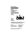
_RRFTSN_N_
:
. CHAJ
IVE
Ti E TILLE
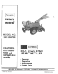
Read SAFETY
RULES and
iNSTRUCTIONS
carefully
o Assembly
o Operating
®Maintenance
. Repair Parts
........
8F__._RS,
and
i m
PART
NO,
,
S_NS-SEARS
i,,,i,ii ......................................
770_7763
P, DEBU6-_
AND
03.,
Cht_I1.
LI_MYI2!D,
60684
Toronto,
IIIl/l'
U_.A.
Canada
,,,,.,,?,
PRINTED IN U,S,A,,
FULL ONE YEAR WARRANTY
For one year from
the date of purchase,
Sears will
repai_ any defect
workmanship
in this TILLER at no charge
If the TtLLER is used for commercial or rental purposes,
thirty days from the date of purchase.
Warranty service is available by contacting
throughout
this warranty
!
in material
applies
or
for onry
the nearest Sears store or Service Center
the United States..
This warranty
gives you specific
Jegai rights,
and you may afso have other
rights
which vary from state to state..
Sears, Roebuck and Coo
Sears Tower
BSC 41-3
Chicago,
DODOg
D Da 0 _J_
Q9_0_0
QD 0 D_ 000001_
D_
000
QO 0000____90
2
IL 60684
na
_oDa@
ooooooo
D_ _
IMPORTANT
__is suggested that this manual be read in its entirety before attempting
manual in a safe place for future reference and for ordering replacemen!
This unit is shipped WITHOUT
for proper fuel and amount,.
Your tiller is a precision
al! times
GASOLINE
orO1L
After assembly,
see operaiing
piece of power equipment,
not a l::lay thing
Therefore
SAFE OPERATION
or operate
section
Keep this
of this manual
exercise extreme
caution
at
PRACTICES FOR TILLERS
't. Read the Operating
and Service Owner's
Manual carefully,
Be thoroughly
familiar with
the controls and the proper use of the equipment..
2. Never allow children to operate a power tiller°
Only persons welt acquainted with these rules
of safe operation
should be allowed to use
your tiller
3
to assemble
parts
Keep the area of operation
clear of a]f
persons, particularly
small children and pets.
11, Do not fill gasoline tank while engine
is
running. Spilling gasoline on hot engine may
cause a fire or explosion,
12. Do not run the engine while
gases are deadly poisonous.
1;3. Be careful
indoors,
not to touch the muffler
engine has been running, it is hot.
Exhaust
after the
14, Before any maintenance work is performed or
adjustments
are made, remove the spark plug
wire and ground it on the engine block for
added safety.
4. Do not operate equipment
when barefoot or
wearing open sandals
Always wear substantial footwear.
15
Use caution when tilling near buildings
and
fences, rotating
tines can cause damage or
injury.
5. Do not wear loose fitting
get caught on the tillen
l&
Before attempting
to remove rocks, bricks
and other objects from tines, stop the engine
and
be
sure
the
tines
have
stopped
completely.
Disconnect
t,he spark plug wire
and ground to prevent adctdental starting.
clothing
that could
6. Do not start the engine unless the shift
is in the neutral (N) position.
7. Do not stand in front
starting the engine.
of
the
tiller
tever
while
,
Check the tine and engine mounting
bolts
frequent intervals for proper tightness°
at
8. Do not place feet and hands on or near the
tines when starting the engine or while the
engine is running.
t8, Keep all nuts, bolts and screws tight to be
sure the equipment
is in safe working
condition
9. Do not leave the tiller
engine running,,
19.
t0.
Do not walk in front
engine ts running.
unattended
of the tiller
with
while
the
the
Never store the equipment
with gasoline in
the tank inside of a building where fumes may
reach an open flame or spark, Allow the
engine
to coot
before
storing
In any
enclosure°
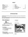
UNDEX
Warranty ....................................
Safe Operation Practices .....................
Introduction
...................................
Contents in Hardware Pack .........................
Tiller Identification
................................
Assembly Instructions .........................
Adjustments
.....................................
Con trots .......................................
Engine Preparation ...............................
2
3
4
5
6
7
9
t0
13
Operation ........................................
13
Tilling ..........................................
14
Tilling Hints .....................................
15
Maintenance .................................
15
Off-Season Storage ............................
!9
Transmission--Repair
Parts ..................
20
Tiller-- Repair Parts ................................
22
Parts Information
.....................
Back Cover
INTRODUCTION
This Product has been designed,
and performance.
engineered
and manufactured
to give you the best possible
dependability
Should you experience any problem you cannot easily remedy, please contact
your nearest Sears, or
Simpson-Sears
Service Department. They have well qualified, competent trained technicians
and the proper
tools to service or repair this unit.
PRE-ASSEMBLY
3o Gas (regular)
4. Cleaning
rag
_NOTE
The right and teft side of your tiller
is determined from operator's position.
Before any step is undertaken, the instructions
that step should be read through.
PARTS IN CARTON
for
TOOLS REQUIRED:
1. (2) 7116" Socket, open or box wrench.
2. (1) 9t16" Socket, open or box wrench.
3, (1) V_" Flat Screwdriver.
4. (1) Adjustable Wrench.
MATERIALS
REQUIRED:
1. Funnel (for gas and oil--NOTE:
DO NOT MIX)
2. S.AoE.-30 O11--2¾ pints
FIGURE 1.
4
E
C
G
G
J
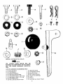
FIGURE
2, (SHOWN
IN FULL
SCALE)
NOTE
THE
LETTERS
LISTED
BELOW
WILL
BE
REFERRED TO THROUGHOUT THE FOLLOWING
TEXT FOR EASIER HARDWARE
IDENTiFICATION,
LIST OF CONTENTS
A
B
C
D
E
F
G
H
(2)
(2)
(2)
(2)
(t)
(t)
(3)
(2)
IN HARDWARE
Shoulder Bolts
Flat Washers
BeltevitleWashe_s
Hex Nuts 318-18 Thread
Hex Screw 318-24 xi.,25" Long
Hex Screw !/4,20 x 1 ,,75" Long
Flat Washers 318"
Hex Locknuts 3/8-24 Thread
PACK:
I
J
K
L
M
N
O
P
(1)
(1)
(2)
(2)
(1)
(1)
(1)
(1)
Gear Shift Knob
Compression
Spring
Hair Pin Cotter
Serf Tapping Screws
Hex Nut _-.20Thread
Lever
Ferruie
Hex Jam Nut 3f8-24 Thread
F
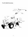
TILLER
IDENTIFICATION
Depth Slake
Adj..stmen{
Pin
Shield
Klick Pin
Belt
Cover
3ounter Weight
6
Tine
Assemblies
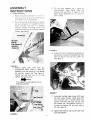
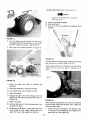
ASSEMBLY
INSTRUCTIONS
1
D
Handle Assembly
A
Place the handle assembly
in p,:;s,'",k)n Or:
Tip
the tiller
forward,
counterweight
Slide
through
titler as shown
depth
stake
adjustment
lock in place
so it rests
on
depth
stake
up
in figure
6, Pull
pin on tiller
to
the tiller so that the holes in handle Ime up
w_th holes in mountir, g bracket
g
Place flat washer (B} and bellevi_le washer
(C) over shoulder on shoulder
bolt (A)
Place shou}der
bolt and two washers
through
handle
mounting
holes
and
secure with lie× nut (D) from the inside of
handle. See figure 4
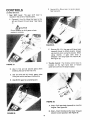
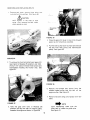
FIGURE 6,
E
Attach front end of depth bar assembly to
transmission
housing
Slip depth bar over
bolt and secure with hair pin cotter (K).
See figure 7
FIGURE 4.
C Remove
depth
stake
from
tiller
and
preassemble
depth stake to drag bar
assembly with hex screw (E), flat washer
(G) and hex Iocknut (H). See Figure 5
Tighten
nut and bolt, but do not over
tightem Parts must pivot.
NOTE
Flat washer must go against
drag bar assembly
@
slot on
FIGURE 7
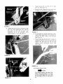
F_
Assemble notched edge of gear shift lever
so notch faces forward.
Place gear shift
lever through slot in handle panel and
bottom hole over weld stud_ Secure with
flat washer (G), compression
spring (J),
another flat washer (G) and hex locknut
(H)° See figure 8,
G. Tighten hex Iocknut
stud. See figure 8
FIGURE 5.
7
until nut is flush
with
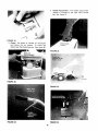
Thread
shift
ferrule
rod
Secure
in figure
[0)
on
See figure
ferrule
other
in gear shift
11) with
er_.d of
gear
10
llair
lever
pin cotter
(as shown
(K),
FIGURE 8.
H. Thread hex jam nut (P) on one end of gear
shift rod, then thread gear shift rod into
ball joint
on the top of pivot
horn
assembly,
10 to 12 complete
turns,
approximately
1,,t,inch. See figure 9,
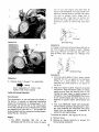
FIGURE 11.
K,,
To assemble
the handle adjustment
lever.
hook
handle
adjustment
rod (already
on
handle)
into lever
Hook
to the outside
See figure 12
L,,
Place handle adjustment
handle and secure with
lever in place on
hex screw (F) and
tocknut
(M)
See figure
12
tighten
handle
adjustment
pivot freely.
Do not over
iever
mt'sl
FIGURE 9.
FIGURE 12.
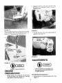
M. Throttle
Control
Lever_
NOTE
The throttle control may have four
holes in the lever bracket, The holes
on the outside edge are to be used
for mounting on this unit° See figure
!3.
FIGURE 10.
8
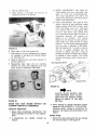
2, Change oil after first 2 hours of operation and
every 25 hours thereafter_ Check oil every 8
operating hours.
FIGURE 13.
Place throttle control lever up through the handle
panel and secure with two self tapping screws (L),
using a 1/4" fiat screwdriver.. See figure 14_
FIGURE 15.
3- Fill fuel tank with clean fresh regular grade of
gasoline. See figure 16..
FIGURE 16.
ADJUSTMENTS
FIGURE 14.
Engine is shipped
without oil,
ENGINE
PREPARATION
1o Before starting, Fill crankcase with 2_A pints
of SAE 30 heavy duty detergent oil, Be sure
that engine is level, See figure 15,
After all assembly is completed, this
final adjustment
must be made prior
to initial operation.
Gear Shift Rod Final Adjustment
1. Place ktick pins in freewheeling
figure 17,
position.
See
Handle Adjustment
Lever. (See figure t9 )
NOTE
Figure 19 is _,iewed
of handle panel
from
A_ Use if not enough free play
B. Normal setting°
C, Use If pin wilt not withdraw
bracket.
the bottom
completely
from
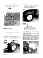
FIGURE 17.
2
Pull the depth bar adjustment
pin and move
the depth stake all the way down. so the tines
DO NOT" touch the ground
See figure 18
3
Block the front wheels as shown
in figure
18
FIGURE 19.
To make the above adjustment
loosen hex iocknut
and reposition
the rod in Hole A, B or C.
Additional adjustment for the gear shift rod can be
made after lhe tiller has been in service for a
while
FIGURE 18.
4. Place the
position.
gear
5, Place the throttle
shift
lever
in Neutral
(N)
in the Start position
6. Pull choke lever out (if engine
Is cold)
7. Start the engine_
8
Engage the gear shift
gears with the engine
Neutral (N)_
lever through the five
running and return to
FIGURE 20.
9. Stop the engine,
10o Remove the hair pin from ferrule
of gear shift lever,
When the belt has become worn and/or stretched
or the friction wheel has become worn, make the
following
adjustment.
and pull out
11. Place gear shift lever in first gear (and pull
lever to rear of slot), Adjust the ferrule to fit
gear shift lever, and replace the hair pin,
1. Move the control
bracket
to the bottom
on the pivot horn assembly and readjust
gear shift rod, See figure 20_
10
hole
the
E
CONTROLS
Neutral (N)--Move
See figure 22.
lever to center detent
Location and Use°
t.
Gear Shift Lever: The gear shift lever
located in the center of handle Dane!.
A
is
Forward (1 thru 5)--Move the lever to the
left and forward for each gear See figure
2rl
L_CAUTtON
DO not attempt to shift gears unless
engine is running°
.i:: :=
FIGURE 23.
F. Reverse (R)--Pull
the gear shift lever back
(upward) slowly to obtain reverse Always
use caution when using the reverse When
using
reverse,
if gear shift
lever is
released it wtll snap back into neutral (N).
See figure 23.
2o Throttle Control: The throttEe control lever is
located
on the right hand side of handle
panel and controls the engine speed.
FIGURE 21,
B o Use (1) first and (2) second gears
breaking the sod for the first time
C.
when
Use (3) third and (4) fourth gears when
tilling soil which has been tilled before,
D. Use(5) fifth gear for pulverizing
soil.
'2,,
FIGURE 24.
A. StopmPull
lever back (upward)
engine. See figure 24.
to stop the
B. Start--Push
throttle control lever forward
(down) to start position. See figure 25.
FIGURE 22,
11
4 HandleAdjustment: The handleacljus[men_
releaseis located on the right hand handle
bar_ See figure
FIGURE 25,
3. Choke: The choke is located on the engine
just below the air cleaner,
To choke the
engine pull the choke lever out., See figure 26.
FIGURE 28.
FIGURE 26.
FIGURE 29.
RGURE
27.
FIGURE 30.
12
27.
S(;ue,:,_:'e
_:nd
place
;:,OSilionS
up
on
hat]die
adiustmen!
',he
handle
m
one
See
_Igures
2_
29
of
B
iever
n_ne
Egt
30 a,"_::_ 2,1
Drive
position
is when
the klick
pin
is
inserted
into lhe _nside hole of ;,,,heel shall
(hole
Drive
in wheelilub)
as shown
m figure
position
iS used for tilling
33
NOTE
Figure
28 is viev,.ed
filler for c;arily
frc_r'n !he fr(.,n_ c)f
FIGURE 33.
TO START
FIGURE
_
31.
tiller
has freewheeling
and drive
positions
1
A
Freewheeling
position is when the klick pin is
placed in the outer hole on wheel shaft, as
shown in 32.
2,
P}ace
the
gear
shift
position
See figure 22
Place
the
position
Freewheeling
is used for transporting
the tiller to
and from the work area, with the engine off and
the gear shift lever in Neutral (N} position
:ii!:(
CAUTION
BE SURE
NO ONE IS STANDING
IN
FRONT
OF THE 'TILLER WI-'IILETHE
ENGINE
lS RUNNING
OR BEING
STARTED.
OPERATION
Your
ENGINE:
ne{_t_at
lever
in
(N)
FAST
25
Choke engine
Pull choke lever out, See figure
26. Once the engine starts,
push the tever up
4,
Stand at side of tiller, grasp lhe starter
handle
and pull out rapidly,
Return
it slowly
to the
engine,
Repeat as necessary
See figure 34,
FIGURE 3,4.
13
control
in
3
:
FIGURE 32.
throttle
See ligure
lever
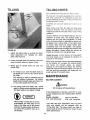
TILLING
TILLING HINTS
Soil conditions
are important
for proper tilling
The lines will not readily penetrate dry, hard soil
This may contribute
to excessive
bounce and
difficult handling of the tiller Hard soil should be
moistened prior to tilling,
Extremely
clump_
wet soil will
cause
soil
to bali up or
When tilling in the Fall, all vines and tong grass
should be removed. This will prevent vines trom
wrapping around the tine shaft which slows tilling
operation.
The best method will be determined
by the soil
condition°
In some soils, the desired depth is
obtained the first time over the garden. In other
soils, the desired depth is obtained by going over
the garden two or three times. In the latter case,
the depth stake should be raised before each
succeeding
pass over the garden,
and passes
should be made across the length and width of the
garden alternately.
Rocks which are turned up
should be removed from the garden area°
FIGURE 35.
1. Adjust the depth stake by pulling the depth
stake adjustment
pin. Release the depth
stake. See figure 35.
2. Lower the depth stake for shallow tilling
raise the depth stake for deeper tilling.
and
3o Select gear on handle
propel itself.
will
A. For tilling
the depth
the tines.
panel
and tiller
Handle Pressure: Further control of tilling depth
and travel speed can be obtained by variation of
pressure on the handles.
When using the depth stake a downward pressure
on the handles will increase the working depth
and reduce
the forward
speed.
An upward
pressure on the handles will reduce the working
depth and increase the forward speed. The type of
soil and working
conditions
will determine
the
actual setting of the depth stake.
in sod, raise the depth stake so
bar is one to two inches above
MAINTENANCE
This setting is used for breaking up the
sod and shallow cultivation. For further
depth ratse the depth stake and make one
or two more passes over the area.
BELT REPLACEMENT:
_CAUTION
B. For tilling loose and sandy soil, further
depth In tilling can be achieved by raising
the depth stake to its highest setting.
iNG,
e._,b.o4_..o
WARN
Do not use an off-the-shelf
belt,
If belt replacement is rc-quired, order belt or belts
by part number from your nearest Sears Service
Center.
Part No. 75443224
Part No. 75443221
518" x 26" Short Belt
5!8" x 52" Long Belt
_
When tilling, if a hard spot or rock is
encountered, the tines may rift the
back of the tiller out of the ground
and start to walk across the ground,
To correct this problem raise up on
the handles.
Your tiller has been engineered with the above
belts and should
not be replaced
with an
off-the-shelf
belt. The above belts are made of
special material (Kevtar Tensile) for longer life and
better Derformanceo
14
REMOVING
AND
REPLACING
BELTS
1_ Remove bell cover remove three boils, two
nuts and !wo fiat washers. See figure 36.
_CAUTION
HOT muffter
in the area of belt
cover
Only remove the belt cover
when engine is cool
FIGURE 38,
4
Place the gear shift lever in one o! the forward
gears (as far forward as possible)
5
Pull the idler pulley down by hand and remove
the belt from idler pulley and transmission
pulley See figure 39
FIGURE 36.
2 To remove the front belt (short) pull gear shift
lever back to Reverse (R) position and hold,
With a 7t !6" wrench remove three screws and
Iockwashers
holding the friction
disc, See
figure 37°
FIGURE 39.
6. Remove the forward
belt (short) from
variable speed pulley and slip beit off
engine pulley. See figure 40_
the
the
7. Remove rear belt (long) and replace with new
belts
FIGURE 37.
NOTE
Upon reassembly
make sure the
short belt is inside the guide pins.
See figure 41_
3. Hold the gear shift
lever in Reverse (R)
position
and slip the belt off engine pulley,
towards the engine as shown in figure 38
15
tion of your new engine and after each 25
hours of use thereafter to ensure proper lubrication of internal parts for trouble free operation and to prevent
costly
repair due to
excessive
wear. (Take care to remove dirt
around li!ler plug.) Be sure oil level is maim
tained full to point of overflowing
Seefig{,re
42.
_.
FIGURE40,
Oil Filler
Oil Level
Plug
FIGURE 42_
TO change oil remove drain plug (figure 43) and tip
the tiller forward while engine is warm. Replace
drain plug. Remove oil fiiler cad and refill with
SAE 30 heavy duty detergent
oil
Replace filler
cap..
Oil Drain
Plug
FIGURE 43,
FIGURE 41.
2
Use only a good grade of fresh, clean, regular
gasoline
Do not use gasoline that has been
sitting
for a long period
of time.
Stale
gasoline may cause engine to run poorly or
not at all.
3_,
Keep your engine CLEAN. Wipe off all spilled
fuel and oil Keep the engine clean of foreign
matter and be sure the cooling
fins on the
cylinder are kept clean to permit proper air
circulation.
You must REMEMBER that this is
an air cooled engine and free flow of air is
essential to proper engine performance and
life.
8o Reverse steps 1 through 7 for reassembfy.
NOTE
Upon reassembly
of friction
tighten three screws equally.
disc,
CARE AND MAINTENANCE:
Tran smission:
The transmission
is pre-lubricated
and sealed at
the factory. It requires no additional
lubrication
unless the transmission
is disassembled°
To fill
with grease, lay the left half of the transmission
on its side, add 28 ounces of Plastilube #1 grease
and assemble the righ! half to it. This grease can
be purchased from your nearest authorized dealer.
(Order Part NOo737-0133.)
4_
Your must SERVICE YOUR AIR CLEANER,
The air cleaner prevents damaging dirt, dust,
etc.. from entering
the carburetor
and being
forced into the engine and is important
to
engine life and performance.
To remove air cleaner:
Engine:
1_ You
MUST
CHANGE
crankcase after the first
See figures
44 and 45.
A. Remove screw.
THE OIL
in the
two hours of opera_
B.. Remove air cleaner carefully
from entering carburetor.
16
to prevent
dirt
air cleaner
A.
C.
Take
apart
D,
Wash element
in detergent
and
squeezing
similar
to a sponge
solution
by
B.,
FIGURE 44.
E
Wrap foam in cloth and squeeze dry.
F. Coat element with two tablespoons
of engine
oil, squeeze to distribute
and remove excess
oil. See figure 45.
G. Wipe air cleaner body
remove excess oil.
with
same solution
to
INITIAL ADJUSTMENT.
See figure 46
Close needle valve (turn clockwise)
then
open 1_,_ turns (lurn counterclockwise)
This initial
adjustment
will permit
the
engine to be started and warmed up before
makine final adjustment
FINAL, ADJUSTMENT.. See _igure 46.. With
engine running at fast operating
speed
(approximately
3,000 RPM without
load)
close the needle valve (turn clockwise)
until engine starts to lose speed (lean
mixture),
Then slowly open needle valve
(turn counterclockwise)
pasl the point of
smoothest
operation
until engine
just
begins
to run unevenly
This mixture
should be rich enough for best performance under load. Hold throttle in idling
position
Turn idle speed adjusting screw
until fast idle is obtained (1.750 RPM),,
Test the engine and if it tends to stall or
die out,
it usually
indicates
that the
mixture is slightly
lean and it may be
necessary to open the needle valve slightly
to provide a richer mixture
This richer
mixture may cause a slight unevenness in
idling
Idle Adjusting
H,, Reassemble
(See figure
44,) by inserting
element into body and snapping cover into
place, fasten to carburetor with screw.
Screw
._.
!._'P_--;_. ..._,
_"_-_ ":-2:'-,_ i;,..e
,_:.o,o::.::_:.,c':.'
Needle Valve
FIGURE 46.
W
ALWAYS ALLOW SEVERAL
SECONDS BETWEEN EACH ADJUSTMENT FOR THE ENGINE CARBURETOR TO REACT TO THE NEW
SETTING
FIGURE 45.
NEVER RUN YOUR ENGINE WITHOUT
CLEANER COMPLETELY ASSEMBLED°
AIR
3. Never attempt to change maximum
engine
speed as THIS IS PRESET AT THE FACTORY.
Excessive speed, caused by by-passing
the
governor, can cause extensive damage to your
engine.
Carburetor Adjustment:
1. Never make unnecessary
adjustments.
The
factory settings are correct for most applications.
2. If adjustments
follows:
NOTE
are
needed,
proceed
SPARK PLUG:
as
1• Remove the spark plug each time you change
the oil and inspect it. See figure 47,
17
.:
A. The electrodes should be kept clean and
free OF CARBON. The presence of carbon
or excess oil will greatly
deter proper
engine performance.
1. Working outdoors, drain all fuel from the fuel
tank° Use a clean dry cloth to absorb the small
amount of fuel remaining in the tank, then run
the engine
until all fuel in carburetor
is
exhausted.
DO NOT
SMOKING,
FIRE.
FIGURE 47.
2. Drain all the oil from the crankcase
(this
should be done after the engine has been
operated
and is still warm) and refill
the
crankcase with clean new oil. See figure 15.
B. If possible, check the spark plug gap (area
between electrodes)
using a wire feeler
gauge. This plug gap should be .030.
3. Disconnect
the spark plug wire and remove
the spark plug from the cylinder. Pour about
six drops of engine oil tnto the cylinder,
and
then pull the recoil starter several times to
spread the oil on the cylinder wall. Replace
the spark plug, but DO NOT connect the wire.
2. if you need a spark plug refer to the parts list
for the proper replacement spark plugo
ADJUSTMENT OF THROTTLE CONTROL CABLE
1, Place the
position.
throttle
control
lever
in
stop
4. Clean
the
thoroughly.
2. Loosen the casing clamp screw and move the
throttle control wire in as far as possible.
3. Tighten
48.
DRAIN
FUEL
WHILE
OR IF NEAR AN OPEN
engine
and
the
entire
tiller
5. Wipe tines with oiled rag to prevent rust.
TILLER INSTRUCTIONS
FOR WINTER
OPERATION (under 40 °F,)
the casing clamp screw. See figure
TIRE PRESSURE
Engine Lubrication. Drain the summer engine oil
while engine is warm_ Refill with new "winter
grade" oil. Run engine until warm to distribute the
new winter oil.
Tires should be inflated from 8 to 15 p.sot.
Use oil "for service" SC, SD, or SE. Use 5W-20 or
5W-30.tf not available, use !0W, or 10W-30.
Fuel, Replace any summer gasoline on hand or in
the fuel tank with fresh winter-grade
gasoline. Use
lead-free or leaded "regular"
grade automotive
gasoline. Winter fuels have additives
for faster
starting. Keep fuel tank fuif.
_NOTE
Many automotive gasolines no longer contain "de-icer_" A can of gasline de-icer fluid added to your gasoline supply will help maintain
the
engine's winter reliability.
Cold Starting
FIGURE 48.
OFF-SEASON
1. Be sure to use proper winter-grade
gasoline,
STORAGE
If the tiller is to be inoperative for a period longer
than 30 days, the following
precautions
are
recommended.
Keep your tiller in a weatherproof
dry area. If stored for over 30 days the following
steps will protect the essential engine parts from
gum deposits,
Hints
2. Dectutch all possible
3, Set governor
18
oi! and
external loads.
control at tow-speed
position.
4. Turn carburetor needle valve approximately
!t8
turn
counterclockwise.
(Richer
fuel
mixture)
This
will improve cold weather
starting and operation.
NOTES
19
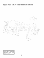
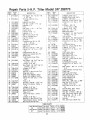
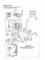
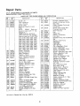
Repair Parts 5 H.P. TilUer ModeB 247.298770
55
-.
52
53
12
;3
5t
29
_9
31
.oT_i
O.e_0o,,oceo
°4
Plastilube
#1 grease,
part no. 737-0133,,
Orderi
|
!
20
20
54
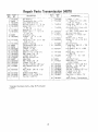
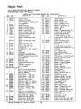
Repair Parts Transmission
'
REF., i
PART
NO_ t
NO
T
t i74t"0155
2 ! 04822
3 738-0379
4 7t4._0122
5 750..O379
6
7
7170210
750-.0378
8
9
04867
736-0259
10 1741-0t89
1
15
05034
_736-0329
!712-0138
1721-0102
736-02t9
736-0't69
7'12-0214
04872
736-0219
736-0169
7t0-041I
!7t0-060t
18
19
20
21
22
23
i24
736-0242
29
3O
72! -0162
721-0102
71 2-0138
.................
"R I_-F'-]'
DESCRIPTION
ND
Ball Bearing
Transmission
Ass / --,-q _,.
Input Shaft 5,8- D_a
Sq Key3!16×3'1
]., ":5 Lg
Spacer ,637 t D × }'_.1 0 D
x 85- L c_.
Sprocke
9- _. 50 = Ph,'l_
Spacer 537 f -' 2. "_8! O D
x 1.44'" Lg
Tine _ha,t As:_ :.
FI-Wasr
! O' I D x ! 62
OD
.: 09
Flange Bfg _; 00
D _.1 188
O.D ;,' t 12
Gasket_Housmg
Transmission
Ass y._L t-_
Bearing Housing
L-Wash
b_" Scr "
Hex Nut _4_-28Thd..*
Seal 1.0' I.D. xl 38" O E
Bell Wash 318'1 D.
L-Wash 318' Scr "
Hex Nu! 3/8-24 TI d "
Side Plate
Bell Wash 3!8 ;D
L-Wash 3f8' Scr "
Hex Scr 3f8-16 x 4..00" Lg*
Hex TaotiteSft6-'.8
x 75'
Lg
Bell Wash..345t
D x 88
OD
Gasket_Side
Ptale
Seal1,.0" t D xl.38'
O D
Hex Nut 1/_-28 Thd.."
'
I
: :::'
PART
_
Hardware
Items--May
1
736-0329
, :.0-03_8
i
,_
._-.8-0104
,_
7 _3-02 26
.5
"6
T
712-0375
7' 3-023 T
7_3-016-
' 8
0
7"_3-0154
750-031
i ,,_
f ,I2
7 _,3-0222
7,_8-018A
43
750-0374
_4
7,_1-0t89
I5
7,36-025£
;6
_7
04873
7! 3-022[
_8
_9
50
31
52
53
54
750-03!4
7! 0-0195
736-021 9
710-0629
736-01 59
736-0t19
710-0627
1
Be Purchased
21
i
NO,
55_756-0297
"Standard
Local ty.,
04878
--
DESCRIPTION
L-Wash
'_ Scr "
i "¸
H_.L Sleeve 3 c l D
D O x3..3SLg
Flange Brg :328 f D _ 713
3D
×,75
Cl_a_n #50--5 8 Pitch x 52
L nt,;s E qciless
H.,', Cen: L-Nut 318-1(-; Thd
S[,, !":)c_et
HUE, Ass y
#_20 Cha,.-_ _? Pitch × 57
-inks
M._sler Lii*,k '_2" P tch
S:,acer 1 fl"l D x 20
O D
x 68
Sprocket Ass y
F._nge Brg..6281
D _ 753
OD x75
Hub Sleeve 38 i D x 625
OD
Flange Brg. " 00 ! D x
1 .I 88 O D
FI-Wash i 0 ; O x 1 (;2'
O_D
Axle Sheh A_s'y.
#_20 Chain _:," Pitch _ 42
Links Eqdtess
Spacerl.¢,'
I D x20"
O.D
Hex Sc',r '..,_-28x 62" Lg"
Betfevitle Wash
Hex Scr 318-24 x275'
Lg.."
F,-Wash 5116' Scr"
L..Wash 5!11;" Scr"
Hex L-Scr 5'!6-24
x 75"
Lg*
Input Pu!_ey_Traqsmission
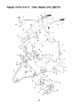
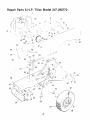
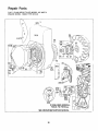
Repair Parts 5°HoPo TiB_erModel 247°298770
4
5
2
I
4t
93
t3
73
\,
37
22
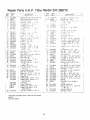
Repair Parts 5=H.P. Tiller ModeB 247.298770
REF.
I No.I
PART
No.
i
2 1746-0304 )
3 !747-0255
4 1710-0136
5:749-0268
6 1720-01 80
7 _712-0107
8 04830
9 04831
10 749-0269
1!
720-0! 83
1 2 04892
13 714-0104
14 736-0101
'15 732-0!93
16
17
712-0214
04833
:t!8
710-0344
714-0115
20
21
22
23
732-0306
747-0256
747-0252
04804
24
710-0623 !
25 736-0169 1
26 710-0623
27
26
29
30
3t
32
34
736-0169
736@101
712-0130
04879
04909
04683
711-0599
35
36
37
742-0197
7I 0-0191
04857
38 736-0'I 69
39 712-0241
40 714-0145
4I
742-0! 98
42 i04855
46 736-0169
47 1712-0130
48 104878
49 1712-0267
DESCRIPTION
REF
.................
Hex Wash Hd Tan Scr #B
x .50" Lg,"
ThrottleControl A._sy
Comp
Handle Lock Rod
Hex Scr _,_-20 x 1 75 Lg °
Handle--R
H
G ri p
"I_
Hex Cen; L-N_4 : , -J.
Tt7:J
Clutch Grip
Handte Panel -'ss
HandleLH
Ball }(nob ot8-_6 _hd
Clutcn Handle As."y,,
Hair Pin Cotter
Fl-Wash
Compression
Spri:,g 88
QD _.8I Lg
Hex Nut 3!8-2,3 Thd"
Depth B:_r
HexScr
3!8-!6 x 1.50' Lj "
Cotte ,Pro _,8" D,_ x 1.00'
Lg"
Compression
Spr,'_ 9
Depth Bar Adjustn;er!
Pi.q
Hinge Rod
Tine Shield Hinge Flap
Ass'y.
Hez Wash., Hd. Self Tap Scr
3f8-1B x .75" Lc
L-Wash 3/8 ' Scr '
Hex Wash, Hd, Self Tap :;or
3t8-16 x .75" L9
L-Wash, 318" Scr "
Fi-Wash,
Hex Ins L-Nut 3/8-t6 T,_:t
Drag Bar Ass'y.
Inner Tine Adapte" Ass'y
Outer Tine Adapter Ass'y
Clevis Pin 318" Dia, x t 75'
Lg
Tine--L,.H
Hex Scr. 3f8-24 ), 1o25" Lg."
Outer Tine Ass'y, Comp L,H
L-Wash, 3t8" Sc[*
Hex Nut 318-24 Thd,*
Hair Pin Cotter
Tine--RH
Inner Tine Ass'y, 3omp L.Ho
L-Wash., 318" Scr *
Hex Ins. L-Nut 318-16 Thd.,
Transmission
Ass'y, Cornp,
Hex Nut 5116-18 Thd.*
PART
!NO
NO.
-I-'_
5_
52
53
54
736-01 t 9
04850
736-01 69
7t2-0116
714-0474
,_5
736,,0290
56
57
58
9
736,0119
738,0258
736.0105
710.0623
(0
61
62
63
04841
7t 0 0601
7I 0-,0216
71401 t5
64
04796
7120130
73G0169
714-0474
65
66
68
69
15
04806
747-0278
723-0156
04812
712@221
711-0663
732-0"132
714-0474
76
736-0253
77
78
79
80
84
85
8_
87
747-0254
726-011_
726-0108
7t2-0158
748-0516
04819
736-0289
738-0143
712-0267
T36-0119
71G0458
8_
89
9C
91
9_
04792
746-0305
7I0-0152
712-0181
748-0!50
9,.
9z
711-0198
712-0711
_t
72
Z3
DESCRIPTION
L-Wash,. 5t16" Scr,*
Handle Post[loner Ass'y,
L-Wash., 3/8' Scr "
Hex Ins, L-Nut 3t8-24 Tha
Cotter Pm 1/8" Dia, x .75"
LG*
F!-V_ash
630 I D
x I.,0'" O D. x .,063
L-Wash, 5116 Scr.*
SMd, Scr
50 _ ,,25
Bellevtlle Wash
HexWash
Hd Self Tap Scr
3'8-16 x 75" Lg,
.,,,)n rol Brk;
Hex Wash, Hd, Self Tap Scr
Hex Scr. 3/8-16x
75" Lg.*
CoRer Pin 1 i8" Dia x 1 00'"
Lgo*
Tree Sh,eld As,s'y
Hex Iqs L-Nut 3t8-_6 Thd,.
L-Wash 3 8"Scr"
Cotter Pin 1 I8" Dia, x ,,75Lg,*
Pivot Horn Assy.
Gea, Shift Rod
Rod End 31B-2,'- TnC
Pivot Brkt,, Ass y,,
Hex Ins L-Nut 5t8-I6 Thd,,
LocKing Pin
Compression
Spring
CoHer Pin t/8'
Di& x ..75"
Lg."
Bell, Wash 505 I.,D x 1,00"
O_D,,
Lower Handle Conbot Rod
Push Cap
Push Cap 3i8"' Rod
Hex Nut 5!16-'8 Thd*
Pivot Handle Brg
Pivot Handle Link
Bushing Wash
Shtd. Scr..500'
Dia., x _,660
Hex Nut 5t16-!8 Thd,*
L-Wash 5t16" Scr.,"
Cam Bolt 5!16-1B x 1,75"
Lg,
Handle Mig. Brkt Ass'y_
Conduit and Wire
Hex Scr, 3!8-24 x 1 O0" lg,, °
Hex Top L-Nut 3!8q6 Thd
Sleeve Brg 50 I,D, x ,62
O_D,, x 1,12" Lg.
Ferrule
He, Jam Nut 3t8-24 Thd,
TINE CHART
4
'
Not Shown Inner Tine As'y. Comp,--R
H 10 854 i
42
l Inner Tine Ass'y, Comp,_L.
H,,t04855!
Not Shown IOuter Tine Ass'y. Comp.--R,, H ,,04856 I
37
!Outer TineASS'?,Comp,--L,H i 048___571
23
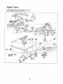
Repair Parts 5oH.P, TiBBerModel 247°298770
I
t
,/
21
58
41
..
14
54
24
Parts 5=H.P. Tiller Mode
247,298770
PART
NO.I
1
2
3
4
5
6
7
8
NO.
DESCRIPTION
752-0668
04869
736-01t-1
710-Dt2t
75a-3224
717-0343
754-322"
750-338-
9
10
11
12
t3
14
15
!6
17
18
i9
756-92 c,'
736-01 59
736-01 _ :_
710-0627
7'12-0t 3'9
736-0169
756-0225
04836
736@329
7! 0-0230
736-0133
20
21
22
33
34
37
38
39
7t0-0151
047q0
710-0599
05034
74'1-01 55
714-0122
"138-0372
710-0502
40
4't
736-01 69
7t 0-0623
42
43
44
45
46
47
04878
71 2-01 38
741_0246
710-0347
716_0102
734-0832
73"_0833
i
7'34-0338
734,-O339
04874
I
04875
Engine
...................
B & S "' 30} '_
.b--_:,1!
'-"" _.....15
' '_
Bell Cover SuF'por! Ass y
Internal L..-V',,as_ _
L,, r.
Hex Scr ' "
:5
'V-Beh9
,: '
_+
VariaLte Bp,,;e:: A:+
' -Beit 5 8
:2 L_+
Space: _37 t :
.£,..,
;4.t
;hq. ut
i
i
i
N{L. L__
:!.
.,-:.....
,_ )I
Items_May
.....
_ ..........
7! 3-011B
5 ) i 04:360
,,m)-0t _0
{: ._
71:'-0!L1
, --?,'0,:'_'C
71 ]-02!g
_:_
:
5_ i 7-i 2-0;.)f7
57 ; 735-01 ] 9
5_ {,4B44
5
732-O! 53
6;
34_64
712-0138
; 5t
7t 2-0_ 30
i 63 04637
_6_ 736-0256
_ _ 1,_;_._.
-e
Fi..W.3sr 5 16 3,':
L Wa:.q 5 6
S:;, "
He_×L "_ " :-'_15-2_ ;: 75
"
Hex :",s L44uI L_.6.._6 :'t::.
L-Wash 3/8" Sc,'.
Fi-ld,:_-.. " "_',
_ D'_,._
FriclK)n 3;sC
L-Wa.sh.. :_ S,;r "
hex Scr _-'-28 _ _0 Lg
Fi-Wasb
375 i D x 1 _5
0 O :, ! 0
Hex "_
..... < . O0 Lq
,.,,o.-_Beit C,ov=_
Hex Wa._h Hd Se f "t'Bp Scr
Beanng .Housin£_
Bail Bea"ing
So, !.:,_y 3f16 x 7F. Ig
ShouJder Spacer
Hex Sell Tap Scr }t8-!6
<
1.25' Lg
L-Wash 3/8" Scr
Hex SF tap Scr 3B-16 >
75" Lg.
Transmission
Ass_, C3m:)
Hex Nut !4-28 Thc..
Bearing 1.0"1 D x 1.12" Lg
Hex Scr 318-16 x I 75' L
Snap Ring
Wheel Ass'y. Comp--R
H
Wheel Ass'y. Comp._L.P'
(Not Shown1
Tire Only
Inner Tube Only
Wheel Hub Ass'y..-R
H.
Wheel Hub Ass:y.-L.H,
(Not Shown:)
Hex Scr 318-24 x 1 00" Lzj "
"Standard Hardware
Locally..
t-Not Illustrated
NO
DESCRIPTION
He< Sc" 5 !6-18 x -*-_Lg
Weigh! Mt.._ BrKt
Ft-.A'a_r, 5"_
I D x 7:3
') D. , 'h56
He,: Ser_. . !',ut 3 8-24
"f:d "
He:: Nu,!) i6 iST]d
'
L-',.¢.aSP _'_t6 S:r "
et
j_2
_[3
_4
_6
_7
71 0-0599
04876
736-0173
712-0117
7oo-0t , o
710-0195
710-0599
714-0105
710-0380
750-0382
0_,863
r:8
9
751-o0233
750-0379
;di Pi"Arm ,_ss /
-4-t,'_Cent L...Nu1 _ -28 Thd
-te_ ins _ Nut 3/8-16-hd
/a iabie S_-_ee.lBrkt A.';s'y
:1 dash
625 I D x 1.25
O D
Coder Pir'l t_"'
Dia x 75l_g"
Sh:_uloer Scr 5fl ._ 267
HexSr.:r "_20 xt 25"_g
"
Hex Ins ,_hiLt _4-20 Tt}d
Con;ro_ Brkl
_e>: Wasr_ PId Se f Tap Scr
Hex Scr .=_6-18 x 50' Lg
L;Wash 5'16
Scr"
Friclion Wheel Ass'y.
Engine Pulley Ass'y 5_8 V
< 75 tD
He.x Wash Hd Serf Taa Scr.
Belt Cove_ Ex:ensian Ass'y
Fl-Wast_ ";:" S:_ .
Hex Cenl L-Nut 1,_-28 Thc
Fl-Wash
:.;_'" Sc_
Hex Scr. _4-2B x 62" Lg.."
Hex Wash Hal. Se;f Tap Ssr
Key 3/16).3!16
× 1 00" Lg
Hex Scr 5t16-t8 _ 175 Lg."
Spacer
Rear Bell -...,o,__rSuppo t
Brkt.
Muffler Deffe{:1or
Spacer.637
t D x .78t Q D
770-7763
7j7-8517
Owner's Manual
Warranty Label
[
!65
i 7" 1-04":.I
i 73s-03so
6,7 I 7t 0-0106
6_q . 7t 2,,0324
69 '04841
73 710-0623
71 . 7'10-062t
72 , 736-01_ 9
74 _ 05080
,"_.= 756-0301
_6
,77
7B
79
K .85:'
_
Be Purchased
25
Lg
TILLERACCESSORIES
Hilling Plow (Must be used with "V" Bar Frame
Adapter)
Six Tang Cultivator (Recommended
use of Depth
Gauge Wheels)
"V" Bar Frame Adapter (Recommended
use of
Depth Gauge Wheels)
Four Shovel Cultivator(Must
be used wilh "V" Bar
Frame Adapter)
Depth Gauge Wheels
Tine Cultivating
Shields
Wheel Weights
Tire Chains (13" x 5")
32" Angle Dozer Blade
Front Hitch Mount (Required to mount 32" Angle
Dozer Blade)
26
Repair Parts
5-H.P. CHAIN DRIVE TILLER MODEL 247.298770
ENGINE MODEL, 130202 TYPE 08"15-03
!72_6L3
5
337
,_....z";7 6i_)
--20!
5_
232
61_i,_z
b2zil_
_,,5__F- _-_
15
31-35B
GASKET SET]
REQUIRES
SPECIAL TOOLS
TO INS'FALL
SEE REPAIR INSTRUCTIONNtC_NUAL
27
Repair Parts
5-H.Po CHAIN DRIVE TILLER MODEL 247,298770
ENGINE MODEL 130202 TYPE 0815-03
\
3O4
24
\
23
76 71 70 67
Z
75
373 _
65,..._;
305
REQUIRE8 SPECIAL
TOOLS TO INSTALL
SEE REPAIR INSTRUCTIONMANUAL
28
Repair Parts
5_H.P** CHAIN DRIVE TILLER MODEL 247.298770
ENGfNE MODEL 130202 TYPE 0815-03
_
124
,19j
62_
534
t63
Z67 f526
265
29
Aepair Parts
5-H,P. CHAIN DRIVE TILLER MODEL 247.298770
ENGINE MODEL 130202 TYPE 0815-03
PARTS LIST FOR ENGINE
REF,
PART
NO.
NO,
MODEL NO. 130202_0815-03
REF,
DESCRIPTION
Cylinder Ass'y.
Bushing--Cylinder
NOTE: Requires special tools
for installation.
Seal--Oil
_ 89660
211542
Head--Cylinder
7 *270383
Gasket--Cylinder
Head
8 294178
Breat her--Valve Chamber
9 *27549
Gasket--Valve
Cover
!0 93394
Screw--Breather
Mtg. Sere
!1 66578
Grommet_Breather
Tube
t2 *270080
Gasket_Crankcase
_ .015"
thick (Standard)
*270125
Gasket--Crankcase_.005"
thick
*270126
Gasket_Crankcase=.,009"
thick
13 93368
Screw_Cylinder
Head
(2-3132" lgo)
14 93369
Screw_Cylinder
Head
(2-I 5132" Ig.,)
15 91249
Ptug_Pipe,
_A" Std,, Square
Head
16 261148
Crankshaft
18 297602
Cover Ass'y_ _Crankcase
19 297603
Bushing_Crankcase
Cover
NOTE: Requires special toots
for installation,,
20 294606
Seat_Oil
21 66768
Plug--Oil
Filler
22 93032
Screw_Crankcase
Cover
Mtgo Sere
23 297229
Flywheel_Magneto
24 61760
Key_Ftywheel
PISTON RING SETS:
NOTE: For Chrome Piston
Ring Set,_Stdo _ze--order
Part No. 299742.
298904
Piston Ass'y_--Std.
298305
Piston Ass'y._.,010"
O,,S
298906
Piston Ass'y.--O20"
O.So
298907
Piston Ass'y.--.030"
OoS.
298982
Ring Set--Std.
Piston
298983
Ring Set_.010"
COS,, Piston
298984
Ring Set--c020"
O.S,, Piston
298985
Ring Set--.030"
O.S. Piston
26026
Lock--Piston
Pin
298909
Pin Ass'y._Ptston--Std.
298908
Pin Ass'yo-- Piston-- °005"
CoS.
299430
Rod Ass'y.--Connecting
NOTE: For Connecting
Rod
with .020" undersize Crankpin
Bore--order
Noo 390459.
221890
Dipper--Connecting
Rod
221876
Lock_Conno
Rod Screw
92296
Screw--Connecting
Rod
in Gasket
Set--Part
No, 297615°
NO,,
33 211119
34 261044
35 260552
36 26478
37 222443
40 93312
45 260642
46 211117
52 *27355
55 1299431
56 295871
391977
297565
*Included
PART
NO,,
57
58
294303
66884
59
6O
65
230228
66728
93067
66
67
68
70
71
73
74
75
76
81
90
95
298310
21"1383
63770
298436
22'1653
221923
93490
220865
68238
222263
299437
93499
96
97
114
116
117
!18
124
147
148
149
152
154
211203
2992'12
66594
' 65978
230590
i23433
193357
1230591
i22235
26336
260575
92634
! 63 27660
180 297600
181 392304
190 93341
191 "27911
30
DESCRIPTION
Valve-- Exhau st
Valve-- Intake
Spring--Intake
Valve
Spring--Exhaust
Valve
Guard--Flywheel
Retainer--Valve
Spring
Tappet --Valve
Gear--Cam
Gasket--Carburetor
Mtg_ (2)
Housing_
Rewind Starter
Puttey_ Rewind Starter
(includes 63" long rope)
If longer rope is required,
order rope no. 66894 and cut
to length.
Spring--Rewind
Starter
Rope_Rewind
Starter_
63" long
(For use with Plastic Pulley)
If longer rope is required,
order rope No. 66894 and cut
to length°
Pin--Starter
Grip
Grip_Starter
Rope
Screw_Stamped
Steel Hsg..
Mtgo Sere
Clutch Ass'y,_Rewind
Starter
Housing_Starter
Clutch
Ball--Clutch
Ratchet_Rewind
Starter
Washer_Ciutch
Retainer
Screen_Starter
Pul Iey
Screw_Sem
Washer_Spring
Washer_ Ratchet Sealing
Lock--Screw
Carburetor Ass'y.
Screw--Throttle
Valve to
Shaft Sere
Throttle_Carburetor
Shaft and Lever,---Throttle
Gasket_Needle
Valve Nut
Packing--Needle
Valve
Nut--Needle
Valve
Vatve_Needle
Screw_Hex
Head
Seat_ Needle Valve
Washer--Needle
Valve (2)
Spring--Needle
Valve
Spring--Throttle
Adjustment
Screw_Machine,
Rd. Hd._
5-40 x 5 / 8"
Gasket_Air
Cleaner Mtg.
Tank Ass'y,--Fuel
Cap--Fuel
Tank
Screw--Fuel
Tank Mtg. Sem
Gasket--Fuel
Tank Mtg. (2)
Repair Parts
5-H.Po CHAIN DRIVE TILLER MODEL 247.298770
ENGINE MODEL 130202 TYPE 0815.o3
PARTS LIST FOR ENGINE
"EF.j
200
201
202
203
204
DESCRIPTION
NO.
221480
260661
260678
297718
230844
93838
260695
391737
22155!
221517
93491
391966
220680
222450
260478
221535
93496
391313
299410
93158
221511
93042
308
333
335
337
MODEL NO. 130202-0815-03
PART
221512
298316
934'14
2988O9
340 26018
341 93381
*included
in Gasket
Guide--Air
Link--Governor
Link--Throttle
Crank-- B ell
Bushi ngmGovernor
Lever
(Flat)
NOTE:
230943
Bushing-Governor Lever (with 1/2" dia..
Flange) or:
23688 Bushing--Governor
Lever (with 318" dia. Flange)
Used on type Nos. 0130, 0148,
0't74, 0181, 0184. 0185, 0194,
0196, 022!, 0230, 0233, 0237,
0239, 0247, 0255, 03'16, 0352,
0353, 0359, 0364, 0406, 0414,
0416, 0418,04t9,
0422, 0425,
0431, 0435, 0438, 0439, 0451,
0458, 0471, 0480, 048t, 0485,
0514, 0520, 0540, 0568, 0573,
0607, 0608, 0620, 0635, 0636.
Screw--Shoulder
Spring--Governo
_
Gear--Governor
Washer--Thrust
Lever--Governor
Control
Rivet--Governor
Control
Lever Mtg.
Lever Ass'y.--Governor_
For V4" Dia. Crank
Washer_Governor
Lever
Washer_Governor
Lever
(_A" loD,.)
Spring--Governor
Link
Clamp_Oasing
Screw--Sere
Muffler_Exhaust
Housing_BIower
Screw_Blower
Hsg, Mtg.
Shield_Cylinder
Screw_Cylinder
Shield Mtg.
Sern
Cover_Cylinder
Head
Armature--Magneto
Screw_Armature
Mtg. Sere
Plug_Spark
(with Gasket)
1 _/2" High--37-42
M. Mo
Spring_-Breaker
Arm
Sorew_Breaker
Arm Mtg
Sere
Set--Part
No.. 29761&
65704
93042
345
220366
346
93705
356
357
358
372
373
375
295413
91539
297615
220477
92987
294628
392
260455
270026
221377
93265
210959
93141
260374
93343
221514
230722
67838
93322
27987
297036
231079
Plunger_ Breaker Point
Screw--Condenser
Clamp
Mlg, Sem
Cover--Breaker
Point and
Condenser
Screw--Dust
Cover and
Flywheel Guard M_g
Wire--Ground
Key
Gasket Set
Clamp_Condenser
Nut_Hex
Breaker Points and Condenser
Set
Spring--Fuel
Pump
Diaphragm
Diaphragm
Cap--Spring
Pin--Diaphragm
Cover
Cover--Diaphragm
Screw_Diaphragm
Cover
Spring--Connector
Screw--Tank
Brkt, Mtg.. Sere
Clamp--Breather
Tube
Tube_ Breather
Grommet-- Breather Tube
Screw_Air
Cleaner
Element_Air
Cleaner
Cleaner Ass'y _Air
Bushing_Governor
Crank
I.D,)
92613
59z 231082
6O8 390463
609 260694
391813
61 z 296811
93704
6I3
614 93306
615 93307
616 231077
621 297472
626 230749
634 270167
643 221321
676 222261
684 299060
725 221885
851 221798
Bolt_Governor
Lever
Nut_Hex_10-24
Starter Ass'y, _Rewi nd
Spring--Throttle
Link
Fuel Pipe and Clip Ass'y
Pipe_Fuet
Screw--Muffler
Mtg.
Cotter--Hair
Pin
Retainer_E-Ring
Crank--Governor
(_,_" Dia. )
Switch--Stop
Spacer--Governor
Crank
Washer, Throttle Shaft (Felt)
Cup--Air
Cleaner
Deflector_
Exhaust
Needle Valve K,t
Shield_Heat
Cable Terminal,--lgnition
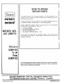
HOW TO ORDER
REPAUR PARTS
Sears
.....
i i/
H
i,,
The Model Number wil! be found slamped
chassis. Always mention the Model Number
repair parts for your fiUer.
i
on a plate attached to the
when requesting
service or
All parts listed herein may be ordered through SEARS ROEBUCK
or SIMPSON SEARS LIMITED RETAIL or CATALOG STORE,
manual
WHEN ORDERING REPAIR PARTS, ALWAYS
INFORMATION
AS SHOWN lN THIS LIST.
EL O.
247=298=(70
1
2_
3.
4
The
The
The
The
GIVE THE
AND CO
FOLLOWING
PART NUMBER
MODEL NUMBER 247.298770
PART DESCRIPTION
NAME OF MERCHANDISE-Tiller
if the parts you need
electronically
transmitted
expedited handling,
are not stocked
locally,
your order will
be
to a Sears Repair Parts Distribution
Center for
Your Sears merchandise takes on added value when you discover that Sears
has over 2,000 Service Units throughout
the country,
Each is staffed by
Sears-trained,
professional
technicians,
ROEBUCK
and
PART NO. 770-,7763
__NS._--'HIAIqS
AND
CO., Chill.
L1lV_'r_,
60684
Toronto,
U_A.
Ca_da
PRINTED IN U.S.A,