1
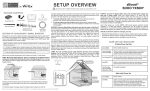
zBoost YX230 In‐Vehicle Cell Phone Signal Booster User Guide DMAN‐0018 REV C zBoost YX230 User Manual Table of Contents 1. Package Contents ............................................................ 2 2. Important Safety Information .......................................... 2 A. Limited Warranty ....................................................... 3 B. Limitation on Liability ................................................. 3 C. FCC/IC Regulations .................................................... 3 3. Electrical Specifications ................................................... 4 4. YX230 Installation ........................................................... 5 5. Technical Support ........................................................... 8 6. Troubleshooting ............................................................. 8 Entire contents © 2009 Wi‐Ex, Inc. All rights reserved. No part of this publication may be reproduced, stored in a retrieval system, or transmitted in any form or by any means, electronic, mechanical, photocopying, recording, or in any information storage and retrieval system known or to be invented, without the written permission of Wi‐Ex, Inc., 1 Meca Way, Norcross, GA 30093. The specifications of this guide are subject to change without notice. Wireless Extenders, Inc. assumes no liability for the use of the information contained herein, nor does Wireless Extenders, Inc. assume any liability arising out of the application or use of any product. 1 IMPORTANT! Read instructions completely before installation. 1. Package Contents YX230 Part Number DMAN‐0018 APRD‐0010 CANT‐0019 CANT‐0018 CCBL‐0014 Description Installation Guide zBoost In‐Vehicle Amplifier Unit Interior Patch Antenna Exterior Magnetic Mount Antenna 12V DC Cigarette Lighter Adapter Record the serial number found at the bottom of your zBoost YX230 Car Extender for future reference: Serial #_______________________________________ 2. Important Safety Information The YX230, as all Wi‐Ex Products, comply with FCC and Industry Canada regulations. Follow all guidelines in the installation and instruction manual and read this information completely before beginning the installation procedure. Never operate the system in an unintended application. NOTE: Installer should have all cell phones, within 50 feet of the installation area, turned off while performing the installation. Only after unit is installed should cellular phones be turned on and tested with the system. 2 A. LIMITED WARRANTY – LIMITED WARRANTY ‐ The Wi‐Ex System by Wireless Extenders, Inc. warrants to the purchaser for a period of one (1) year from the date of purchase, but in no event longer than two (2) years from the date of manufacture, that its products identified above under Package Contents and sold hereunder will at the time of shipment be free from defects in material and workmanship and will conform to Wi‐Ex specifications stated in this manual. If products sold hereunder are not as warranted, Wi‐Ex shall, at its option, repair or replace the product; provided that: 1) proof of purchase (a copy of a valid receipt or invoice) and written notice of the alleged defect are received by Wi‐Ex within the warranty period stated above; 2) customer obtains a written Return Authorization from Wi‐Ex for the product; 3) the product is returned in a protected shipping container at customer’s expense; and 4) Wi‐Ex determines that the product does not meet the warranty stated herein. If Wi‐Ex determines that the product does not meet the warranty, Wi‐Ex will pay for transporting the repaired or exchanged product to the customer. This warranty shall not apply to any products Wi‐Ex determines to have been, by customer or otherwise, subject to mishandling, misuse, neglect, improper testing, repair, alteration, damage, assembly or processing that alters physical or electrical properties. As the above products depend on the existence of a sufficient signal to enhance, Wi‐Ex cannot and does not warrant that the products will work in all locations. In addition, Wi‐Ex does not warrant that interference will not occur in a particular installation. This limited warranty is expressly in lieu of and excludes all other warranties, express and/or implied including but not limited to warranties of merchantability and of fitness for a particular purpose, use or application and for all other obligations or liabilities on the part of the seller, unless such other warranties, obligations or liabilities are expressly agreed to in writing by Wi‐Ex. B. LIMITATION ON LIABILITY – In no event shall Wireless Extenders, Inc. Be liable to the customer, or any other person or entity, for any direct, indirect, special, punitive, incidental, exemplary or consequential damages, or any damages whatsoever, even if Wireless Extenders, Inc. has been previously advised of the possibility of such damages, whether in action under contract, negligence, or any other theory, arising out of or in connection with the use, inability to use, or performance of the information, services, products, and materials available from this manual. These limitations shall apply notwithstanding any failure of essential purpose of any limited remedy. Because some jurisdictions do not allow limitations on the exclusion or limitation of liability for consequential or incidental damages, the above limitations may not apply to you. C. FCC/IC REGULATIONS – FCC: SO4YX230 The zBoost YX230 Car Extender has been tested and found to comply with the limits of FCC rules part 22 and part 24. These limits are designed to provide reasonable protection against harmful interference. This equipment generates, uses and can radiate radio frequency energy and if not installed and used in accordance with this instruction manual, may cause harmful interference to radio communications. However, there is no guarantee that interference will not occur in a particular installation. If this equipment does cause harmful interference to radio or other electronic reception, which can be determined by turning the equipment off and on, the user is encouraged to correct the interference by one or more of the following measures: Reorient or relocate the outside signal antenna Increase the separation between the Amplifier and Antennas. Connect to isolated power with a cable going directly to the battery Repositioning the cables may also eliminate interference Consult the dealer or an experienced electronics technician for help 3 This equipment complies with FCC radiation exposure limits set forth for an uncontrolled environment. This equipment should be installed and operated with a minimum distance of 20cm between the radiator and the operator’s body. This transmitter must not be co‐located or operating in conjunction with any other antenna or transmitter. IC: 5544A‐YX230 The manufacturer's rated output power of this equipment is for single carrier operation. For situations when multiple carrier signals are present, the rating would have to be reduced by 3.5 dB, especially where the output signal is re‐radiated and can cause interference to adjacent band users. This power reduction is to be introduced by means of lowering input power or gain reduction and not by an attenuator at the output of the device. WARNING: Changes or modifications not expressly approved by Wi‐Ex could void the user’s authority to operate the equipment. 3. Electronic Specifications Frequency: TX: 824‐849 MHz/1850‐1910 MHz RX: 869‐894 MHz/1930‐1990 MHz Gain: Up to 42 dB (Dual Band, Bi‐Directional) Output Power: Uplink : +20dBm (maximum peak power) Downlink : +10dBm Type of Modulation: CDMA, GSM (Class V), TDMA, GPRS, EDGE, HSPA DC Supply Voltage: 7.5 to 24.0V Current Draw: 300ma at 12.0 VDC. Battery Power: Switch on/off via ignition switch or 12V DC Adapter Operating Temperature: ‐30 to 60° C Dimensions: 4.88 x 3.9 x .733 in. Weight: 21 oz. FCC ID: SO4YX230 under rules part 22 and 24. IC: 5544A‐YX230 4 4. Portable Installation Step‐by‐Step Guide Note: Before installing the zBoost Car Extender, please read the entire contents of this Installation Guide. Setup Overview: Item Description 1 zBoost In‐Vehicle Amplifier Unit 2 Interior Patch Antenna 3 External Magnetic Mount Antenna 4 12V DC Cigarette Lighter Adapter 5 Quantity 1 1 1 1 WARNINGS The YX230 complies with FCC/IC regulations. Follow all guidelines and read this information completely before beginning the installation procedure. Never operate the system in an unintended application. All cellular phones in the vicinity of the Amplifier should be turned off during installation. Only after unit is installed should cellular phones be turned on and tested with the system. Make sure to connect to a 12V source that loses power when vehicle is off, or make sure 12V DC CL Adapter switch is off. Battery will drain otherwise. Only the provided power cable is to be used with the Wi‐Ex systems. Using any other power cable will harm the system. The Wi‐Ex’s warranty will be voided if any other power cable is used. Only the antennas provided with the Wi‐Ex system may be used. Use of any other antenna could adversely impact the performance of the system, cause damage to the unit and would void the warranty. Changes or modifications not expressly approved by Wi‐Ex will void the user’s authority to operate the equipment. Installation Instructions We recommend that individuals not accustomed to the installation of mobile electronics seek the services of a professional installer. Step 1. Position Amplifier Unit ‐ Position Amplifier Unit within interior of vehicle and within a 3‐4 ft. reach of a 12V DC Port. Choose a location where it rests flat and is not a hazard to driver (i.e. under seat). Step 2. Position Exterior Magnetic Mount Antenna ‐ Position Exterior Magnetic Mount Antenna on top of vehicle, making sure magnet is secured to metal surface. Then route cable from Exterior Magnetic Mount Antenna and connect to Amplifier Unit. NOTE: Cord will run from exterior to interior of vehicle. Cord is designed to withstand pressure when closed in a door. Step 3. Position Interior Patch Antenna ‐ Position the Interior Antenna with the fewest obstructions between the antenna and the normal operating position of the cell phone. When the Antenna is in the desired position, it should be no less than 8 inches (20cm) from the normal operating position of the cell phone. Next, route the Antenna cable and connect to the Amplifier Unit. Avoid placing the Antenna behind any metallic objects (ie. mirror in sun visor). Do not attach to any metal surface. IMPORTANT: For optimal performance, do not affix Interior Antenna to windshield. 6 Step 4. Attach DC Power Cable ‐ Attach small end of the 12V DC Power Cable to the Amplifier Unit. Insert the remaining end of 12V DC Power Cable into a 12V (cigarette lighter) Port within vehicle. NOTE: To avoid draining battery, when the ignition is off, check that Amplifier is not receiving power with vehicle turned off. The Amplifier’s LED should be off when the vehicle is off. To turn off Amplifier, depress the switch on 12V DC CL Adapter. Step 5. Examine LED light on Amplifier ‐ The LED light on the Amplifier Unit indicates the unit is powered and the unit’s operating status. Attempt to achieve the optimal signal enhancement when positioning both Antennas before making the Antenna placement permanent. Once powered, the Amplifier LED should be Green. Be sure that all cell phones in the vicinity of the Amplifier are turned off during installation. Attach both Antennas and position them to achieve a Green LED. Green LED – Optimal signal enhancement Red LED – Poor signal enhancement If you are receiving a Red LED even after trying different Antenna positions, try powering the unit off and on again. If the Antennas are connected and too close to each other when the Amplifier Unit is turned on, it will be impossible to achieve a Green LED. Step 6. Achieve Optimal Enhancement ‐ Once your LED is Green, you may permanently affix both the Magnetic Mount and Patch Antenna. If LED is Red, adjust the position of the Magnetic Mount Antenna or Interior Patch Antenna until the LED is Green. Step 7. Quick System Check ‐ Put your cell phone antenna directly next to the Patch Antenna. See how many signal strength bars you have. Next, turn the system off (either turn vehicle off or press on/off switch). You should notice a decrease in signal bar strength. The exception is if you are in an area where, with the system off, your phone is at full signal strength. Please note when you turn the system on, if your phone is receiving maximum signal strength you will not see a difference. In order for this quick test to work, you will need to test unit in a less than maximum signal strength area. 7 5. TECHNICAL SUPPORT Locate the Wi‐Ex Car Extender serial number on the bottom of the Amplifier Unit before calling. The serial number must be available to authorize technical support and/or establish a return authorization. For installation technical support, contact your dealer. For system warranty issues, contact Wi‐Ex Support between the hours of 8:30 AM and 5:30 PM EST, Mon‐Fri, at 1‐800‐871‐1612 or visit our technical support website at http://www.wi‐ex.com. The Wi‐Ex Car Extender system must be used with Wi‐Ex authorized equipment. The technical support team will only support Wi‐Ex authorized equipment. Contact your dealer for questions. 6. TROUBLESHOOTING I get a Red LED on the Amplifier – If you are receiving a Red LED even after trying different Antenna positions, turn the power off and on again. If the Antennas are connected and too close to each other when the Amplifier is turned on, it will be impossible to achieve a Green LED. If the LED is not lighted Make sure there is power being supplied to the Unit. Ensure the 12V DC CL Adapter switch is in the ON position. i. Check and see that the Red LED on the Amplifier is ON. If not, there is no power at the plug. ii. Disconnect the power at the Unit and reconnect. Flip the ON/OFF switch on the 12V DC CL Adapter. iii. Make sure the connector is properly connected to the Amplifier Unit. I still can’t make or receive a call on my cell phone. I’m not getting any signal – A cellular signal is still required outside the vehicle for the Amplifier Unit to work. This cannot generate a cellular signal when none exists. This can only amplify an existing signal. I dropped a call – There are many factors which can affect cellular calls, for example, if the cellular signal becomes so weak that it cannot be amplified, the call will be dropped. The LED stays on even after I turn the car off – When using a vehicle’s 12V Port, some vehicles may still provide power with the ignition off. In this case, the 12V DC CL Adapter’s Switch must be in the OFF position or taken out of the 12V Port to prevent the car battery from being drained. I get a Green LED, but the signal on my cell phone does not increase – 8 First, waiting 10‐20 seconds is required before some phones show an increase in the signal strength. Second, make sure the Interior Patch Antenna is facing the user and is within 2‐4 feet. Make sure the Antennas are connected to the Amplifier Unit. I need a technical support specialist – Call 1‐800‐871‐1612 to reach one of our highly trained, technical experts. I need to return the unit – Call 1‐800‐871‐1612 to request a Return Authorization number. A customer service representative will provide you with return shipment instructions. A Return Merchandise Authorization (RMA) number must be provided before returning the product. Wi‐Ex 1 Meca Way Norcross, GA 30093 USA 1‐800‐871‐1612 www.wi‐ex.com support@wi‐ex.com 9