1
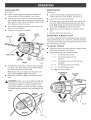
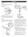
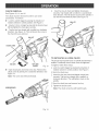
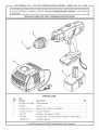
in,, 19,2
Speed /
Model No.
315.114480
Save this manual
future reference
for
•
•
•
.
.
WARNING"
To reduce the risk of
injury, the user must read and understand
the operator's manual before using this
product.
Customer
HeUp Line: 1-800-932-3188
Sears, Roebuck
and Co., 3333 Bevedy Rd., Hoffman
Visit the Craftsman web page www.sears.com/craftsman
983000-194
11-03
Safety
Features
Operation
Maintenance
Parts List
Estates,
RL 60179
USA
US
m
General Safety Rubs .................................................................................................................................................
3-4
m
Specific Safety Rubs .................................................................................................................................................
4-5
m
SymboB ..........................................................................................................................................................................
6
m
Product Specifications ....................................................................................................................................................
7
m
Features .....................................................................................................................................................................
7-8
m
Operation ..................................................................................................................................................................
9-14
m
Maintenance .................................................................................................................................................................
15
m
Exploded View And Repair Parts List ..........................................................................................................................
17
m
Parts Ordering / Service ...............................................................................................................................................
18
FULL ONE YEAR WARRANTY
ON CRAFTSMAN
1/2 in. CORDLESS
DRILL-DRIVER
If this _:RRFT_:MRN1/2 in. Cordless Drill-Driver fails to give complete satisfaction within one year from the date of purchase, RETURN iT TO THE NEAREST SEARS STORE OR SEARS SERVICE CENTER iN THE UNITED STATES,
and Sears wiiI repair it, free of charge.
If this I:RRF'r$1qRN 1/2 in. Cordbss DriiPDriver is used for commercial
90 days from the date of purchase.
or rental purposes, this warranty applies for only
This warranty gives you specific legal rights, and you may also have other rights which vary from state to state.
Sears, Roebuck
and Co., Dept. 8t7WA,
Hoffman Estates,
Your cordless drill-driver has many features for making
the use of this product more pleasant and enjoyable.
Safety, performance, and dependability have been
given top priority in the design of this product making it
easy to maintain and operate.
Look for this symbol to point
Your safety is involved.
out important
tL 60179
,_
safety
WARNING: Do not attempt to use this product until
you read thoroughly and understand completely the
operator's manual Pay close attention to the safety
rubs, including Dangers, Warnings, and Cautions. If
you use this product properly and only as intended,
you will enjoy years of safe, reliable service.
precautions,
it means
attention!!!
WARNING:
The operation of any power tool can result in foreign objects being thrown into your eyes, which can
result in severe eye damage. Before beginning power tool operation, always wear safety goggles or
safety glasses with side shields and a full face shield when needed. We recommend Wide Vision
Safety Mask for use over eyeglasses or standard safety glasses with side shields. Always use eye
protection which is marked to comply with ANSI Z87.1.
_
WARNmNG:
ReadandunderstandaHinstructions. FailuretofollowaHinstructions
Hstedbebw,
mayresuUt
in eUectric
shock,fireand/orserious
personaU
injury.
SAVETHESEmNSTRUCTIONS
WORKAREA
m Keepyourwork areacJeanandwell Jit.CUuttered
benchesanddarkareasinviteaccidents.
m Donot operatepowertooJsin expJosiveatmospheres,suchas in the presenceof flammable
liquids,gases,or dust. PowertooBcreatesparks
whichmayignitethedustor fumes.
m Keepbystanders,children,andvisitorsawaywhile
operatinga powertool. Distractions
carlcauseyou
tolosecontrol.
ELECTRmCAL
SAFETY
m Donot abusethe cord.Neverusethe cord to carry
thecharger.Keepcord awayfromheat,oH,sharp
edges,or movingparts.RepJace
damagedcords
immediately.Damaged
cordsmaycreatea fire.
m A batteryoperatedtool with integralbatteriesor a
separatebatterypackmustbe rechargedonly with
the specified charger for the battery. A charger that
may be suitable for one type of battery may create a
risk of fire when used with another battery. Use battery
MODEL
315.114480
BATTERY PACK
CHARGER
item No. 9 11375
Item No. 9 11041
1323517 or 1323903
1425301
m Use battery operated tooJ only with specifically
designated battery pack. Use of any other batteries
may create a risk of fire. Use only with battery pack
listed.
PERSONAL
SAFETY
m
Stay aJert, watch what you are doing and use
common sense when operating a power tool Do
not use tooJ while tired or under the influence of
drugs, alcohol, or medication. A moment of inattention while operating power tools may result in serious
personal injury.
m
Dress properly. Do not wear loose clothing or
jewelry. Contain long hair. Keep your hair, clothing,
and gtoves away from moving parts. Loose clothes,
jewelry, or long hair can be caught in moving parts.
m
Avoid accidentaJ starting. Be sure switch is in the
locked or off position before inserting battery
pack. Carrying tools with your finger on the switch or
inserting the battery pack into a tool with the switch on,
invites accidents.
m Remove adjusting keys or wrenches before turning
the tool on. A wrench or a key that is left attached to a
rotating part of the tool may result in personal injury.
m Do not overreach. Keep proper footing and balance
at aH times. Proper footing and balance enable better
control of the tool in unexpected situations. Do not use
on a ladder or unstable support.
m Use safety equipment. Always wear eye protection.
Dust mask, nonskid safety shoes, hard hat, or hearing
protection must be used for appropriate conditions.
TOOL USE AND CARE
m Use clamps or other practical way to secure and
support the workpiece to a stabte pJatform. Holding
the work by hand or against your body is unstabb and
may lead to loss of controk
m Do not force tool Use the correct tooJ for your
appJication. The correct tool will do the job better and
safer at the rate for which it is designed.
m Do not use tooJ if switch does not turn it on or off. A
tool that cannot be controlbd with the switch is dangerous and must be repaired.
m Disconnect battery pack from tool or place the
switch in the locked or off position before making
any adjustments,
changing accessories, or storing
the tool. Such preventive safety measures reduce risk
of starting the tool accidentally.
m Store idle tools out of reach of children and other
untrained persons. Tools are dangerous in the hands
of untrained users.
m When battery pack is not in use, keep it away from
other metaJ objects like: paper clips, coins, keys,
naris, screws, or other small metaJ objects that can
make a connection from one terminal to another.
Shorting the battery terminaB together may cause
sparks, burns, or a fire.
m Maintain tools with care. Keep cutting tools sharp
and dean. Properly maintained tools, with sharp
cutting edges are less likely to bind and are easier to
control.
m Check for misaJignment or binding of moving parts,
breakage of parts, and any other condition that may
affect the tool's operation, ff damaged, have the tool
serviced before using. Marly accidents are caused by
poorly maintained tools.
m Use onJy accessories that are recommended by the
manufacturer for your model Accessories that may
be suitable for one tool, may create a risk of injury when
used on another tool.
m Keep the tool and its handle dry, clean and free
from oil and grease. Always use a clean cloth when
cleaning. Never use brake fluids, gasoline, petrobumbased products, or any strong solvents to clean your
tool.
SERVICE
m Toolservicemustbeperformedonly by qualified
repairpersonnel.Serviceor maintenance
performed
byunqualified
personneU
couUd
resuUt
ina riskof injury.
m Whenservicinga tool, useonly identicaJrepJacemeritparts.Followinstructionsin the Maintenance
sectionof this manual.Useofunauthorized
partsor
failuretofoUUow
Maintenance
Rnstructions
maycreatea
riskofshockor injury.
HoJdtool by insulatedgripping
surfaces when performing an operation where the cutting tool may contact
hidden wiring. Contact with a "live" wire will make exposed metal parts of the tool "live" and shock the operator.
ABBmTIONAL
RULES
FOR SAFE OPERATmON
m
Know your power tool Read operator's manuat
carefully. Learn its applications and Jimitations, as
well as the specific potential hazards retated to
this tool Following this rule will reduce the risk of
electric shock, fire, or serious injury.
m
Always wear safety glasses with side shields.
Everyday glasses have only impact resistant lenses.
They are NOT safety glasses.
H'_PORTANT
m
m
RULES
FOR BATTERY
,_
m
Do not charge battery tool in a damp or wet location. Following this rule will reduce the risk of electric
shock.
m
For best results, your battery tool shouJd be
charged in a Jocation where the temperature is more
than 50°F but less than IO0°F. Do not store outside
or in vehicles.
m
Under extreme usage or temperature conditions,
battery leakage may occur, ff liquid comes in
contact with your skin, wash immediately with
soap and water, then neutraJize with Jemon juice or
vinegar, ff liquid gets into your eyes, flush them
with cJean water for at least 10 minutes, then seek
immediate medical attention. Following this rule will
reduce the risk of serious personal injury.
TOOLS
Battery tools do not have to be plugged into an
eJeetricaJ outlet; therefore, they are aJways in
operating condition. Be aware of possible hazards
when not using your battery tool or when changing accessories.
Following this rule will reduce the
risk of electric shock, fire, or serious personal injury.
Do not pJace battery toots or their batteries near
fire or heat. This will reduce the risk of explosion and
possibly injury.
WARMNG: Batteries vent hydrogen gas and can
explode in the presence of a source of ignition, such
as a pilot light. To reduce the risk of serious personal
injury, never use any cordless product in the presence of open flame. An exploded battery can propel
debris and chemicals. If exposed, flush with water
m
Do not operate charger with a damaged cord or
pJug. if damaged, have repJaced immediately by a
qualified serviceman. Following this rule will reduce
the risk of electric shock, fire, or serious personal
injury.
m
Do not operate charger if it has received a sharp
blow, been dropped, or otherwise damaged in any
way; take it to a quaJified serviceman. Following this
rule will reduce the risk of electric shock, fire, or
serious personal injury.
m
Do not disassemble charger; take it to a qualified
serviceman when service or repair is required.
Incorrect reassembly may resuJt in a risk of eJec=
tric shock or fire. Following this rule will reduce the
risk of electric shock, fire, or serious personal injury.
m
To reduce the risk of electric shock, unplug
charger from outJet before attempting any maintenance or cleaning. Turning off controls will not
reduce this risk. Following this rule will reduce the
risk of electric shock, fire, or serious personal injury.
m
Disconnect charger from power supply when not
in use. Following this rule will reduce the risk of
electric shock, fire, or serious personal injury.
n
Save these instructions.
Refer to them frequently
and use them to instruct others who may use this
tool tf you loan someone this tool, loan them
these instructions
also. Following this rule will
reduce the risk of electric shock, fire, or serious
personal injury.
batteryis subjecttoexpbsion.ProperUy
disposeof a
droppedbatteryimmediateUy.
Failuretoheedthis
warningcanresultinseriouspersonalinjury.
m Beforeusing batterycharger,readaHinstructions
andcautionarymarkingsin this manual,on
batterycharger,andproductusingbattery
charger.Followingthisrub wHU
reducetheriskof
eUectric
shock,fire,or seriouspersonaU
injury.
m To reducerisk of injury,chargeonly nickeJ=
cadmiumandnickelmetalhydridetype recharge°
abJebatteries.Othertypesof batteriesmayburst
causingpersonalinjuryanddamage.Followingthis
rub willreducetheriskofelectricshock,fire,or
seriouspersonalinjury.
m Donot exposechargerto wetor damp conditions.
Following this rule will reduce the risk of electric
shock, fire, or serious personal injury.
m
m
m
Use of an attachment not recommended or sold by
the battery charger manufacturer
may resuJt in a
risk of fire, etectric shock, or injury to persons.
Following this rule will reduce the risk of electric
shock, fire, or serious personal injury.
To reduce risk of damage to charger body and
cord, pull by charger plug rather than cord when
disconnecting
charger. Following this rule will
reduce the risk of electric shock, fire, or serious
personal injury.
Make sure cord is located so that it will not be
stepped on, tripped over, or otherwise subjected
to damage or stress. Following this rule will reduce
the risk of serious personal injury.
m
m
Do not abuse cord. Never carry tooJ by cord or
yank it to disconnect from receptacle. Keep cord
from heat, oH and sharp edges. Following this rule
will reduce the risk of electric shock or fire.
An extension
cord should not be used unless
absolutely necessary.
Use of improper extension
cord could result in a risk of fire and electric shock. If
extension cord must be used, make sure:
a. That pins on plug of extension cord are the
same number, size and shape as those of
plug on charger.
b. That extension cord is properly wired and in
good electrical condition; and
c. That wire size is large enough for AC ampere
rating of charger as specified below:
Cord Length (Feet)
25'
50'
100'
Cord Size (AWG)
16
16
16
Note: AWG = American Wire Gage
WARNING:
Some dust created by power sanding,
sawing, grinding, drilling, and other construction
activities contains chemicals known to cause cancer,
birth defects or other reproductive harm. Some
examples of these chemicals are:
o lead from bad-based
paints,
o crystalline silica from bricks and cement and
other masonry products, and
o arsenic and chromium from chemically-treated
lumber.
Your risk from these exposures varies, depending
on how often you do this type of work. To reduce
your exposure to these chemicals: work in a well
ventilated area, and work with approved safety
equipment, such as those dust masks that are
specially designed to filter out microscopic particles.
important:Someofthefollowingsymbolsmaybeusedonyourtool.Pleasestudythemandbarntheirmeaning.Proper
interpretation
ofthesesymbolswiiiallowyouto operatethetoolbetterandsafer.
SYMBOL
NAME
DESiGNATION/EXPLANATION
V
Volts
Voltage
A
Amperes
Current
Hz
Hertz
Frequency
(cyclespersecond)
rain
Minutes
Time
"_
AlternatingCurrent
Typeor a characteristic
ofcurrent
DirectCurrent
Typeor a characteristic
ofcurrent
no
NoLoadSpeed
Rotational
speed,at noload
.../rain
Revolutions
or Reciprocation
PerMinute
Revolutions,
strokes,
surfacespeed,orbitsetc.perminute
SafetyAlertSymbol
Undicates
danger,warningorcaution.
Utmeansattention!!!
Yoursafetyis
involved.
WearEyeProtection
Alwayswearsafetygogglesor
safetyglasseswithsideshieldswhen
operatingthisproduct.
WetConditions
Alert
locations.
Donotexposetorainoruseindamp
Thepurposeof safetysymbolsisto attractyourattentiontopossibledangers.Thesafetysymbols,andthe
explanations
withthem,deserveyourcarefulattentionandunderstanding.
Thesafetywarningsdonotbythemselves
eliminateanydanger.Theinstructions
or warningstheygivearenotsubstitutes
forproperaccidentprevention
measures.
Symbol
Meaning
DANGER:hdicatesan imminently
hazardous
situationwhich,if notavoided,wiiiresultindeathor
seriousinjury.
WARNmNG:Indicates
a potentially
hazardous
situationwhich,if notavoided,couldresultin deathor
seriousinjury.
CAUTION:Indicates
a potentially
hazardous
situationwhich,if notavoided,mayresultin minoror
moderateinjury.It mayalsobeusedtoalertagainstunsafepracticesthatmaycausepropertydamage.
NOTE:
Advisesyouofinformation
or instructions
vitaltotheoperationormaintenance
oftheequipment.
SAVE THESE INSTRUCTIONS
6
}
I Craftsman114480=19,2Vtest criteria
400
in.lb,torque
320
#8x 1.25-in.woodscrewsinlowspeedperbatterypackchargeintopinelumber.
,, 210
3/8-in.diameterhobsperbatterypackchargeinto2-in.nominalpinelumber.
KNOW
YOUR
DRILL-DRIVER
See Figure 1,
Before attempting to use your drill-driver, familiarize
yourself with all operating features and safety
TWO SPEED
GEAR TRAIN
Your drill-driver has a two speed gear train designed for
drilling or driving at H_or LO speeds. A slide switch is
located on top of your drill to select either HI or LO speed.
FORWARD/REVERSE
_
WARNmNG: Do not allow familiarity with your drilldriver to make you careless. Remember that a
careless fraction of a second is sufficient to inflict
severe injury.
KEYLESS
CHUCK
(DIRECTION
SELECTOR
OF ROTATION SELECTOR}
Your drill-driver has a forward/reverse
selector located
above the switch trigger.
WRIST
STRAP
Your drHPdrNer has a keybss chuck that allows you to hand
tighten or rebase drHUbit in the chuck jaws,
A wrist strap is provided to reduce the chances of
dropping your drill-driver. Place one hand through the wrist
strap when carrying tool
SWITCH
BIT STORAGE
To turn your drill-driver ON, depress the switch trigger.
When not in use, bits provided with your drill-driver can be
placed in the storage area located on the bottom of the
motor housing.
Release switch trigger to turn your drill-driver OFF.
SWITCH
LOCK
The switch trigger can be locked in the OFF position. This
feature helps reduce the possibility of accidental starting
when not in use.
VARIABLE
SPEED
This tool has a variable speed switch that delivers higher
speed with increased trigger pressure. Speed is controlled
by the amount of switch trigger depression.
LEVEL
To keep drill bit level during drilling operations, a level is
located on the top and end of the motor housing.
_
WARNING: If any parts are missing, do not operate
your drill-driver until the missing parts are replaced.
Failure to do so could result in possible serious
personal injury.
LEVEL
TWO-SPEED
GEARTRAIN(H-LO)
KEYLESS
CHUCK
REAR
VIEW
DIRECTION
OF
ROTATION
SELECTOR
(FORWARD/REVERSE)
SWITCH
TRIGGER
SCREWDRIVER
BITS
BIT
STORAGE
WRIST
STRAF
BATTERY
PACK
SHOWN
INCHARGER
CHARGER
RED
LEDONiNDICATES
FAST
CHARGING
MODE
GREEN
LEDONAFTER
FAST
CHARGING
CYCLE,
INDICATES
FULLY
CHARGED
BATTERY
PACK
ANDINTRICKLE
CHARGE
MODE.
YELLOW
ANDGREEN
LEDS
ONINDICATES
DEEPLY
DISCHARGED
ORDEFECTIVE
BATTERY
PACK.
CHARGER
SeeFigure1,
Yourchargerhasa "keyhoHe"
hangingfeatureforconvenient,
spacesavingstorage,ScrewsshouHd
beinstaHHed
so that
centerdistancesare4-1/2inchesapart,
8
,_
WARNING:
Do not allow familiarity with your drilldriver to make you careless. Remember that a
careless fraction of a second is sufficient to inflict
severe injury.
BATTERY
PACK
The battery pack for your tool has been shipped in a low
charge condition to prevent possible problems. Therefore,
you should charge it until light on front of charger changes
from red to green.
Note: Batteries wiii not reach fuji charge the first time they
are charged. Allow several cycles (drilling followed by
recharging) for them to become fully charged.
CHARGING
BATTERY
PACK
See Figure 1.
m
Charge battery pack only with the charger provided.
m
Make sure power supply is normal household
voJtage, 120 volts, 60 Hz, AC only.
m
Connect charger to power supply.
m
Place battery pack in charger aligning raised rib on
battery pack with groove in charger. See Figure 1.
m
Press down on battery pack to be sure contacts on
battery pack engage properly with contacts in charger.
m
Normally, the red LED on charger will come on. This
indicates charger is in fast charging mode.
m
Red LED should remain on for approximately 1 hour
then the green LED will come on. Green LED on
indicates battery pack is fully charged and charger is in
trickle charge mode. Note: Green LED will remain on
until battery pack is removed from charger or charger
is disconnected from power supply.
m
Ufboth yellow and green LED come on, this indicates a
deeply discharged or defective battery pack.
Allow battery pack to remain in charger for 15 to 30
minutes. When battery pack reaches normal voltage
range, red LED should come on.
Ufred LED does not come on after 30 minutes, this
indicates a defective battery pack and should be
replaced.
m
After normal usage, a minimum of 1 hour of charging
time is required to fully recharge battery pack.
m
The battery pack will become slightly warm to the
touch while charging. This is normal and does not
indicate a problem.
m
Do not place charger and battery pack in an area of
extreme heat or cold. It will work best at normal room
Note: Charger and battery pack should be placed in a
location where the temperature is more than 50°F bust
less than 100°F.
m
When batteries become fully charged, unplug charger
from power supply and remove the battery pack.
LED FUNCTIONS
OF CHARGER
LED WILL BE ON TO INDICATE
CHARGER
AND BATTERY
STATUS
OF
PACK:
m
Red LED on = Fast charging mode.
m
Green LED on = Fully charged and in trickle charge
mode.
m
Green LED on = When battery pack is inserted into
charger, indicates hot battery pack or that battery pack
is out of or below normal temperature range.
m
Yellow and Green LEDs on = Deeply discharged or
defective battery pack.
m
No LED on = Defective charger or battery pack.
_
CAUTION:
To prevent damage to battery pack,
remove battery pack from charger immediately if no
LED comes on. Return battery pack and charger to
your nearest Sears Service Center for checking or
replacing. Also, if you are removing battery pack from
charger and no LEDs are on, return both battery pack
and charger to your nearest Sears Service Center.
Do not insert another battery pack into charger. A
damaged charger may damage a battery pack.
mMPORTANT
HOT BATTERY
iNFORMATiON
FOR RECHARGING
PACK
When using your drill-driver continuously, the batteries in
your battery pack will become hot. You should let a hot
battery pack cool down for approximately 30 minutes
before attempting to recharge. When the battery pack
becomes discharged and is hot, this will cause the green
LED to come on instead of the red LED. After 30 minutes,
reinsert battery pack in charger. Ufgreen LED continues to
remain on, return battery pack to your nearest Sears
Repair Center for checking or replacing.
Note: This situation only occurs when continuous use of
your drill causes the batteries to become hot. Utdoes not
occur under normal circumstances. Refer to "CHARGING
BATTERY PACK" for normal recharging of batteries. If
the charger does not charge your battery pack under
normal circumstances, return both the battery pack and
charger to your nearest Sears Repair Center for electrical
check.
mMPORTANT iNFORMATION
COOL BATTERY PACK
FOR RECHARGING
Ufbattery pack is below normal temperature range, the
green LED on charger wiii come on. Allow battery pack to
reach normal temperature, then the red LED will come on.
Note: Refer to "CHARGING BATTERY PACK" for
normal recharging of batteries. If the charger does not
charge your battery pack under normal circumstances,
return both the battery pack and charger to your nearest
Sears Repair Center for electrical check.
SWmTCH
SeeFigure2,
ToturnyourdrillON,depresstheswitchtrigger.Toturnit
OFF,releasetheswitchtrigger.
FORWARD/REVERSE
SWITCHTRIGGER
VARmABLE
TO mNSTALL BATTERY
PACK
m
Lock switch trigger on your drill by placing the
direction of rotation selector in center position.
See Figure 5,
m Place battery pack in your drilk Align raised rib on
battery pack with groove inside drill. See Figure 4,
._
BATTERY
PACK
Fig. 2
SPEED
LATCHES
This tool has a variable speed switch that delivers higher
speed and torque with increased trigger pressure. Speed is
controlled by the amount of switch trigger depression.
Note: You might hear a whistling or ringing noise from the
switch during use. Do not be concerned, this is a normal
part of the switch function.
TWO-SPEED
,,,,,
GEAR TRAIN
See Figure 3,
Your drill has a two-speed gear train designed for drilling
or driving at LO (1) or H_(2) speeds. A slide switch is
located on top of your drill to select either LO (1) or NJ (2)
speed. When using drill in the LO (1) speed range, speed
will decrease and unit will have more power and torque.
When using drill in the HI (2) speed range, speed wiii
increase and unit will have less power and torque. Use
LO (1) speed for high power and torque applications and
H_ (2) speed for fast drilling or driving applications.
TWOSPEED
GEARTRAIN(H-LO)
DEPRESS
RELEASEBATTERYPACK
Fig. 4
m Make sure the latches on each side of your battery
pack snap in place and battery pack is secured in drill
before beginning operation.
,_
LO
SPEED
CAUTION: When placing battery pack in your drill,
be sure raised rib on battery pack aligns with groove
inside drill and latches snap into place properly.
Umproper assembly of battery pack can cause
damage to internal components.
TO REMOVE
BATTERY
PACK
m Lock switch trigger on your drill by placing the direction
of rotation selector in center position. See Figure 5,
Hm
SPEED
m Locate latches on side of battery pack and depress to
release battery pack from your drill. See Figure 4,
m Remove battery pack from your drilk
Fig. 3
10
SWITCHLOCK
KEYLESS
See Figure 5,
See Figure 6,
The switch trigger can be bcked in the OFF position. This
feature can be used to prevent the possibility of accidentaU
starting when not in use. To bck switch trigger, pUace the
direction of rotation sebctor (Forward/Reverse Sebctor)
in center position. Note: When sebctor is in center
position, switch trigger is bcked.
Your drHUhas a keybss chuck. As the name implies, you can
hand tighten or rebase drHUbits in the chuck jaws. Grasp and
hoUdthe collar of the chuck with one hand. Rotate the chuck
body with your other hand. The arrows on the chuck
indicate which direction to rotate the chuck body in order to
LOCK (tighten) or UNLOCK (release) the drill bit.
SELECTORWiTH
CENTERLOCK POSITION
REVERSE
DRILL BIT
SWITCH
TRIGGER
LOCK
(TIGHTEN)
Fig, 5
CHUCK
COLLAR
CHUCK
BODY
Fig. 6
WARNING:
Battery tools are always in operating
condition. Therefore, switch should always be locked
when not in use or carrying at your side.
_
REVERSIBLE
See Figure 5,
This tool has the feature of being reversible. The direction
of rotation is controlled by a selector located above the
switch trigger. With the drill held in normal operating
position, the direction of rotation selector should be
positioned to the left of the switch for drilling. The drilling
direction is reversed when the selector is to the right of
the switch. When the selector is in center position, the
switch trigger is locked.
,_
UNLOCK
(RELEASE)
CNUCKJAWS
FORWARD
_
CHUCK
CAUTION:
To prevent gear damage, always allow
chuck to come to a complete stop before changing
the direction of rotation.
To stop, release switch trigger and allow the chuck to come
to a complete stop.
11
WARNmNG: Do not hold chuck body with one hand
and use power of the drill to tighten chuck jaws on
drill bit. Chuck body could slip in your hand or your
hand could slip and come in contact with rotating drill
bit. This could cause an accident resulting in serious
personal injury.
mNSTALUNGBraTS
SeeFigure7,
m LocktheswitchtriggerbypUacing
thedirectionof
rotationsebctorincenterposition.SeeFigure5,
m Openor closechuckjawstoa pointwheretheopeningis slightlyUarger
thanthebit sizeyouintendtouse.
ADo,raisethefrontofyourdrHU
slightlytokeepthebit
fromfallingoutofthechuckjaws.
m Unsert
drHU
bitstraightintochuckthefullbngthofthe
jawsasshownin Figure7.
m TightenthechuckjawsondrHU
bit.
UNLOCK
(RELEASE)
REMOWNG
BraTS
See Figure 7,
m
Lock the switch trigger by placing the direction of
rotation selector in center position. See Figure 5,
m
Loosen the chuckjaws
m
To loosen: grasp and hold the collar of the chuck with
one hand, while rotating chuck body with your other
hand. Note: Rotate chuck body in the direction of the
arrow marked UNLOCK to loosen chuck jaws.
Do not use a wrench to tighten or loosen the chuck
jaws.
m
[:]
CHUCK
COLLAR
from drill bit,
Remove drill bit from chuck jaws.
ADJUSTABLE
TORQUE
CLUTCH
Your drill is equipped with an adjustable torque clutch for
driving different types of screws into different materials.
The proper setting depends on the type of material and the
size of screw you are using.
TO ADJUST
CHUCK
JAWS
LOCK
CHUCK
(TIGHTEN) BODY
RIGHT
m
m
,_
m
Identify the twenty four torque indicator settings located
on the front of your drill. See Figure 9,
m
Rotate adjusting ring to the desired setting.
o 1-4
For driving small screws.
o 5-8
For driving screws into soft
material.
o 9 - 12
For driving screws into soft and hard
materials.
o 13 - 16
For driving screws in hard wood.
o 17 - 20
For driving large screws.
Fig. 7
To tighten the chuck jaws on drill bit; grasp and hold
the collar of the chuck with one hand, while rotating
the chuck body with your other hand.
TORQUE
o 21 - t,_,1 For heavy drilling.
Note: Rotate the chuck body in the direction of the
arrow marked LOCK to tighten chuck jaws.
Do not use a wrench to tighten or loosen the chuck
jaws.
TO DECREASE
TORQUE
WARNING:
Make sure to insert drill bit straight into
chuck jaws. Do not insert drill bit into chuck jaws at
an angle then tighten, as shown in Figure 8. This
could cause drill bit to be thrown from drill, resulting
in possible serious personal injury or damage to the
chuck.
Fig. 9
12
BIT STORAGE
DRILLING
See Figure 10,
See Figure 12,
When not in use, bits provided with your drill can be
placed in the storage area located on the bottom of your
drill as shown in Figure 10.
LEVEL
BIT
STORAGEAREA
_
Fig. 10
WARNING:
Always wear safety goggles or safety
glasses with side shields when operating tools.
Failure to do so could result in objects being thrown
into your eyes, resulting in possible serious injury.
Fig. 12
LEVEL
See Figure 11,
When drilling hard smooth surfaces use a center punch to
mark desired hob location. This wiii prevent the drill bit
from slipping off center as the hob is started. However,
the low speed feature allows starting hobs without center
punching if desired. To accomplish this, simply operate
your drill at a low speed until the hob is started.
The material to be drilled should be secured in a vise or
A convenient feature provided with your drill is a level Ut
is recessed in the motor housing on top and end of your
drill It can be used to keep drill bit level during drilling
operations.
with clamps to keep it from turning as the drill bit rotates.
Hold tool firmly and place the bit at the point to be drilled.
Depress the switch trigger to start tool
Move the drill bit into the workpiece applying only enough
pressure to keep the bit cutting. Do not force or apply side
pressure to elongate a hob.
_
WARNmNG: Be prepared for binding or bit
breakthrough. When these situations occur, drill has
a tendency to grab and kick opposite to the direction
of rotation and could cause loss of control when
breaking through material. If not prepared, this loss
of control can result in possible serious injury.
When drilling metals, use a light oil on the drill bit to keep
it from overheating. The oil wiii prolong the life of the bit
and increase the drilling action.
Ufthe bit jams in workpiece or if the drill stalls, release
switch trigger immediately. Remove the bit from the
workpiece and determine the reason for jamming.
Fig. 11
18
CHUCKREMOVAL
SeeFigures13,14,and15,
Thechuckmustberemovedin orderto usesome
accessories.
Toremove:
m Locktheswitchtriggerby placingthedirectionof
rotationselectorin centerposition.SeeFigure5,
m Unsert
a 5/16in.orlargerhexkeyintothechuckofyour
drillandtightenthechuckjawssecurely.
m Tapthehexkeysharplywitha malletin a clockwise
direction.SeeFigure13,Thiswillloosenthescrewin
thechuckforeasyremoval.
Inserthexkeyinchuckandtightenchuckjaws
securely.Tapsharplywitha malletin a counterclockwisedirection.Thiswillloosenchuckonthespindle.It
cannowbeunscrewed
byhand.SeeFigure15,
[_IALLET
MALLET
CHUCK
JAWS
Fig.15
HEXKEY
KEYLESS
CHUCK
TO RETIGHTENA LOOSECHUCK
Thechuckmaybecomelooseonspindleanddevelopa
wobble.Periodically
checkchuckscrewfortightness.
Totighten,followthesesteps:
[3 Locktheswitchtriggerbyplacingthedirectionof
rotationselectorincenterposition.SeeFigure5,
[3Openthechuckjaws.
[3 Unsert
hexkeyintochuckandtightenchuckjaws
securely.Taphexkeysharplywitha malletin a
clockwisedirection.Thiswilltightenchuckonthe
spindle.
[3Openthechuckjawsandremovehexkey.
[3 Tightenthechuckscrew.
Note:Thechuckscrewhaslefthandthreads.
Fig.13
Openchuckjawsandremovehexkey.Removethe
chuckscrewbyturningit ina clockwisedirection.See
Figure14,
Note:Thescrewhaslefthandthreads.
SCREWDRIVER
Fig.14
14
,_
Do not abuse power tools. Abusive practices can damage
too[ as wei[ as workpiece.
WARNING:
When servicing, use only identical
Craftsman replacement parts. Use of any other
part may create a hazard or cause product damage,
Only the parts shown on parts [[st, page 17, are intended
to be repaired or replaced by the customer. Ai[ other parts
should be replaced at a Sears Service Center.
Avoid using solvents when cleaning plastic parts. Most
plastics are susceptible to damage from various types of
commercial solvents and may be damaged by their use.
Use dean cloths to remove dirt, dust, o11,grease, etc.
_
_
WARNING:
Do not attempt to modify this too[ or
create accessories not recommended for use with
this too[. Any such alteration or modification is
misuse and could result in a hazardous condition
WARNING:
Do not at any time let brake fluids,
gasoline, petroleum-based products, penetrating oils,
etc. come in contact with plastic parts. They contain
chemicals that can damage, weaken or destroy
plastic.
leading to possible serious persona[ injury.
BATTERIES
The battery pack for your drill-driver is equipped with
nickel-cadmium rechargeabie batteries. Length of service
from each charging wii[ depend on the type of work you
D
Store and charge your batteries in a coo[ area.
Temperatures below 50°F or above 100°F wii[ shorten
battery life.
are doing.
The batteries in this too[ have been designed to provide
maximum trouble free life. However, like ai[ batteries, they
D
Never store batteries in a discharged condition.
Recharge them immediately after they are
discharged.
wii[ eventually wear out. Do not disassemble battery pack
and attempt to replace the batteries. Handling of these
batteries, especially when wearing rings and jewelry,
could result in a serious burn.
To obtain the longest possible battery life, we suggest the
following:
D
Ai[ batteries gradually lose their charge. The higher
the temperature the quicker they lose their charge. If
you store your too[ for long periods of time without
using it, recharge the batteries every month or two.
This practice wii[ prolong battery life.
To preserve natural resources, please
recycle or dispose of batteries properly.
BATTERY PACK
FOR RECYCMNG
This product contains nickel-cadmium
batteries. Local state or federal laws
may prohibit disposal of nickel-cadmium
batteries in ordinary trash.
REMOVAL
AND
PREPARATION
WARNING:
Upon removal cover the battery pack's
terminals with heavy duty adhesive tape. Do not
attempt to destroy or disassemble battery pack or
remove any of its components. Nickel-cadmium
batteries must be recycled or disposed of properly.
Also, never touch both terminals with metal objects
and/or body parts as short circuit may result. Keep
away from children. Failure to comply with these
warnings could result in fire and/or serious injury.
Consult your local waste authority for information
regarding available recycling and/or disposal options.
15
16
CRAFTSMAN1/2 in., 19.2VOLT CORDLESSDRmLLoDRmVER
- MODELNO.315.114480 ._,
in aH correspondence regarding your 1/2 in., 19.2 VOLT CORDLESS DRILL-DRIVER or when ordering
The modeUnumber wHUbe found on a pUateattached to the motor housing. AUways mention the modeUnumber
repair parts.
SEE BACK
PAGE FOR PARTS
ORDERING
mNSTRUCTIONS
2
4
PARTS UST
Key
No.
Part
Number
1
6613401 or 6613402
2
6903323
3
* UtemNo. 9 11375
4
* UtemNo. 9 11041
5
9021107
3073062
983000-194
* Can Be Purchased
Thru RSOS (RetaiJ Special Order System)
17
J