1
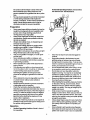
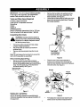
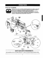
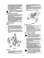
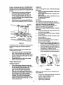
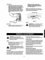
Owner's Manual
CRRFTSMRN
°
33 Ton Hydraulic
Log Splitter
Model Nos'
247.794520
CAUTION: Before using this product,
read this manual and follow all Safety
Rules and Operating Instructions.
Sears, Roebuck And Co., Hoffman Estates, IL 60179, U.S.A.
Printed in U.S.A.
770-10032
(9/98)
Content
Page
Content
Page
Warranty Information ......................................... 2
Service & Adjustment ........................................
15
Safe Operation Practices................................... 3
Off-Season Storage ...........................................
17
Accessories .......................................................
6
Trouble-Shooting ...............................................
18
Assembly ...........................................................
7
Parts Ust............................................................
20
Operation ...........................................................
9
Maintenance ......................................................
13
Spanish version ...............................................
.. 27
ONE-YEAR WARRANTY ON CRAFTSMAN
LOG SPLI'I-I'ER
For one year from the date of purchase, when this Craftsman log splitter is maintained, lubricated, and tuned up
according to the operating and maintenance instructions in the operator's manual, Sears will repair, free of
charge, any defect in material or workmanship.
This warranty excludes the tires, spark plug, oil filter and air cleaner, which are expendable parts and become
worn during normal use.
If this log splitter is used for commercial or rental purposes, this warranty applies for only 30 days from the date
of purchase.
Warranty service is available by contacting the nearest Sears service center in the United States. This warranty
applies only while this product is in use in the United States.
This warranty gives you specific legal rights, and you may also have other rights which vary from state to state.
Sears, Roebuck And Co., DEPT. 817WA, Hoffman Estates, IL 60179
Model Number...247.79452..0. ...................................
Sedal Number ...........................................................
Date of Purchase ......................................................
Record model number, serial number and date of
purchase of the log splitter and keep in a safe place
for futura reference.
Horsepower: ............ :_........... 9
Engine Oil .............................. SAE 30/26 ounces
Fuel Capacity: ....................... unleeded/1 gallon
Hydraulic Fluid ...................... Daxron III/7 gallons
Tire Pressure......................... 30 p.s.i, max.
' Spark Piug(Gap .030") .......... Champion RJ19LM
2
!
This symbol points out important safety instructions which, if not followed, could endanger the personal safety and/or property of yourself and others. Read and follow all instructions in this manual before
attempting to operate your log splitter. Failure to comply with these instructions may result in personal injury.
When you see this symbol--heed its warning.
I
DANGER:
I_lb
manual. As with any type of powerequipment, carelessness or error on the part of the operYourlog
injury tosplitterwas
yourself orbuiltto
others.
be operated according to the rules for safe operation In this
ator can resultin serious njury.If you vio ate any of these ru es, you may cause eer ous
i_
The engine
from
thisreproductive
product contains
cancer,
birthexhaust
defects or
other
harm.chemicals
•
•
•
•
•
•
•
•
This unit should not be towed on any street,
highway or publicroad without checking the
existing federal, local or state requirements.
Such informationmay be obtained by callingyour
state or local bureau of motor vehicles. Any
licensing or modificationsneeded to comply with
federal, local or state vehicle requirements is the
sole responsibilityof the purchaser.*
Make sure you follow the wiring diagram color
codes when installingthe light kit on the log
splitter. (e.g. ground to ground, leftturn to left
turn, etc.). Failure to wire unitcorrectly may
cause the tow vehicle wiringto overheat and/or
the log splitter lights to operate incorrectly.It may
be necessary to replace the turn signal flasher
unit in your tow vehicle if it is not capable of
operating the additional lights on the log splitter.
Before towing the log splitter on a street, highway
or publicroad, vedfy that all lights are functioning
properly and the yellow side reflectors are in
position.Replace bulbs if they are burntout.
Before towing, always check to be certain the log
splitter is correctly and securely attached to the
tow vehicle, and safety chains are in place.
Leave slack in chains for turning allowance.
Use a class I or higher hitchwith a 1-7/8' ball.
Keep ball socket and clamp face lubricated with
chassis grease.
Be sure the coupler is secured to the hitchball
and the lock lever is down tight and locked.
Checkvehicle hitch, ball and couplerfor signs of
wear or damage. Replace any parts that are worn
or damaged before towing.
The coupler must be secured to the log splitter
tongue tube with the original equipment bolts and
nuts. See your authorized service dealer for
replacement parts. Coupler nuts should be
tightened securely (20 foot pounds).
Make sure beam assembly is securely latched in
known to the state of California to cause
the horizontal position and jack stand (if provided)
is pivoted and secured In the up positionbefore
towing log splitter. Never tow with the beam in
vertical position.
Towing
•
I
•
•
•
•
Do not tow the log splitter faster than 45 MPH.
Higher speeds may damage log splitter.
Excessive high speeds may cause the log splitter
to "fishtail" or otherwise become unstable.
Check the tire pressure on the logsplitter tires. It
should not exceed 30 p.s.i, for highway travel.
When parking, storing or usingyour log splitter,
keep the coupler off the ground so dirt will not
build up in the ball socket.
Do not allow anyone to sit or ride on your log
splitter. They can easily fall off and be seriously
injured.
Training
•
•
•
Before operating this log splitter, read and
understand this operator's manual completely.
Become familiar with it for your own safety.To fail
to do so may cause serious injury. Do not allow
anyone to operate your log splitter who has not
read this manual. Keep this manual in a safe
place for future and regular reference and for
ordering replacement parts.
Never use your splitter for any other purposethan
splitting wood. It is designed for this use and any
other use may cause an injury. Your logsplitter is
a precision piece of power equipment, not a toy.
Therefore, exemise extreme caution at all times.
Never allow children to operate your logsplitter.
Do not allow adults to operate it without proper
instruction. Only persons well acquainted with
these rules of safe operation shouldbe allowed to
use your log splitter.
Only the operator is to be near your log splitter
during use. Keep all others, including pets and
children, a minimum of 20 feet away from your
work zone. Flying wood can be hazardous. If a
helper is assisting in loading logs, never activate
thecontroluntilthehelperisclearofthearea.
Moreaccidents occur when more than one
Horizontal Operating Position: Stand behind
the reservoir tank. See illustrations.
person operates the logsplitter than at any other
time.
No one should operate this unitwhile intoxicated
or while taking medication that impairs the
senses or reactions. A clear mind is essential for
safety. Never allow a person who istired or
otherwise not alert to use your log splitter.
Preparation
•
•
•
•
•
•
•
•
•
•
Never wear loose clothing or jewelry that can be
caught by moving parts of your log splitter and
pull you into it. Keep clothing away from all
moving pads of your log splitter.
Wear proper head gear to keep hair away from
moving parts. Always wear protective hearing
devices as needed.
Always wear safety shoes. A dropped log can
seriously injure your foot.
Always wear safety glasses or goggles while
operating your splitter. A piece of splitting log
could fly off and hit your eyes.
Wear leather work gloves. Be sure they are tight
fitting without loose cuffs or draw strings.
Use your log splitter in daylight, or under good
artificial light.
Never operate your splitter on slippery, wet,
muddy or icy surfaces. Safe footing is essential
in preventing accidents.
Never operate your splitter while attached to a
towing vehicle.
Only operate your splitter on level ground and
not on the side of a hill. Itcould tip, or rollinglogs
or poor footing could cause an accident.
Operating the splitter on level ground also
prevents the spillage of gasoline from the fuel
tank.
Never attempt to move the log splitter over hilly
or uneven terrain without a tow vehicle or
adequate help.
Always block the wheels to prevent movement
of log splitter while in operation.
Check the fuel before starting the engine.
Gasoline is an extremely flammable fuel. Do not
fill the gasoline tank indoors, when the engine is
running, or while the engine is still hot. Replace
gasoline cap securely and wipe off any spilled
gasoline before starting the engine as it may
cause a fire or explosion.
Bothends of each log must be cut as square as
possible to help prevent the log from ridingout of
the splitter during operation.
Operation
Vertical Operating Position: Stand in front of
the log splitter.
•
Know how to stop the unit and disengage the
controls.
•
Never place hands or feet between log and
splittingwedge or between log and end plate
dudng forward or reverse stroke.To do so may
resultin crushed or amputated fingers or toes, or
worse, you may lose an arm or foot.
Do not straddle the splitterwhen using it. A slip
in any positioncould resultin a serious injury.
Do not step over your log splitterwhen the
engine is running. You may trip or accidentally
activate the splittingwedge ifyou step over. If
you need to get to the other side, walk around.
Never try to splittwo logson top of each other.
One may fly out and injureyou.
When loading the log splitter,place your hands
on the side of the log, not at the ends. Never
attempt to load your splitterwhile the splitting
wedge is in motion. You may get caught by the
wedge and injured.
Only use your hand to operate the splitting
wedge or control lever. Never use your foot or a
rope or any other extension device. This could
resultin your inabilityto stop your splitter quickly
enough to avoid injury.
Always keep fingers away from any cracksthat
open in the log duringsplittingoperation. They
can quickly close and pinch or amputate your
fingers.
Never attempt to splitwoods across the grain.
Some types of wood may burstor fly out of your
splitter and result in injury to you or a bystander.
•
•
•
•
•
•
•
•
•
•
•
•
•
•
Customer
•
•
•
•
•
Perform all recommended maintenance
procedures before you use your splitter.
Do not service or repair your log splitter without "
disconnectingthe spark plug wire and moving it
away from the spark plug.
Never store the equipment with gasoline in the
tank inside of a buildingwhere ignitionsources
are present, such as hot water and space
heaters, clothesdryers and the like. Allow the
engine to cool before stodng in any enclosure.
Always store gasoline in an approved, tightly
sealed container. Store the container in a cool,
dry place. Do not store in a buildingwhere
ignitionsources are present.
To reduce fire hazard, keep engine free of grass,
leaves, wood chips, and excessive grease and
oil.
For logs that are not cut square, the longest
portion of the log should be rotated down and
the most square end placed against the splitting
wedge.
Keep your work area clean. Immediately
remove split wood around your splitter sothat
you do not stumble over it. Clean chips and dirt
off end plate (wood platform) after each log is
split, or whenever necessary to maintain flat
contact between wood and end plate (platform).
Never move the log splitter while the engine is
running.
Never leave your log splitter unattended withthe
engine running. Shut off the engine if you are
leaving your splitter, even for a short periodof
time. Someone could accidentally activatethe
splitting wedge and be injured.
Do not run engine In an enclosed area. Exhaust
gases contain carbon monoxide. This ododess
gas can be deadly when inhaled.
Be careful not to touch the muffler afterthe
engine has been running. It will be HOT!
If the equipment should start to vibrate
abnormally, stop the engine and check
immediately for the cause. Vibration is generally
a warning of trouble.
When cleaning, repairing or inspecting,make
certain all moving parts have stopped.
Disconnect the spark plug wire and keep the
wire away from the plug to prevent accidental
starting.
The hydraulic system of your log splitter requires
careful inspection,along with the mechanical
parts. Be sure to replace frayed, kinked, or
otherwise damaged hydraulic components.
Fluid escaping from a vary small hole can be
almost invisible. Do not check for leaks with your
hand. Escaping fluid under pressure can have
sufficient force to penetrate skin, causing
serious personal injury. Leaks can be located by
passing a piece of cardboard or wood over the
suspected leak and looking for discoloration.
Should it become necessary to loosen or
remove any hydraulicfitting or line, be sure to
relieve all pressure by shuttingoff the engine
and moving the controlhandle back and forth
several times.
Do not remove the cap from the hydraulic tank or
reservoirwhile your log splitter is running. Hot oil
under pressure could cause injury.
The pressure relief valve on your splitter is
preset at the factory. Do not adjust the valve.
Only a qualified sentice technician should
perform this adjustment.
Completely drain fuel tank priorto storage. This
guards against accumulation of fuel fumes
which could result in a fire hazard.
Never store log splitteroutside without a
waterproof cover. Rain will cause rust on the
inside of the cylinder.
Responsibilities
Do not operate your splitter in poor mechanical
condition or when in need of repair.
Periodically check that all nuts, bolts, screws,
hose clamps and hydraulic fittings are tight to be
sure equipment is in safe working condition.
Where appropriate, check all safety guards and
shields to be sure they are in the proper position.
Never operate your splitter with safety guards,
shields or other protective features removed.
These safety devices era for your protection.
Replace all damaged or worn parts such as
hydraulic hoses and fittings immediately with
manufacturer approved replacement parts.
Do not change the engine governor settings or
over_peed the engine. This increases the
hazard of personal injury. The maximum engine
speed is preset by the manufacturer and is
within safety limits.
Do not alter your log splitter in any manner such
as attaching a rope or extension to the control
lever or adding to the width or height of the
wedge. Such alterations may cause your splitter
to be unsafe.
Important Information
Always:
5
•
•
Use clean fluid and check fluid level regularly
Use Daxron III Automatic Transmission Fluid or
•
10W non-foaming hydraulic fluid.
Use a filter (clean or replace regularly)
Use a breather cap on fluid reservoir
•
•
•
•
•
•
•
•
Make certain pump is mounted and aligned
properly
Use a flexible "spider" type coupling between
engine and pump drive shafts
Keep hoses clear and unblocked
Bleed air out of hoses before operating
Flush and clean hydraulic system before startup after any malfunctionor servicing
Use "pipe dope" on all hydraulicfittings
Allow time for warm-up before splittingwood
Prime the pump before initialstart-up by turning
over the engine with spark plug disconnected
•
Split wood with the grain (lengthwise) only
Never:
•
•
•
•
•
•
•
Use when fluid is below 20 ° F, or above 150 ° F.
Use a solid engine/pump coupling
Force pump when mounting
Operate through relief valve for several seconds
Attempt to adjust unloading or reliefvalve
settings without pressure gauges
Operate with air in hydraulic system
Use Teflon tape on hydraulic fittings
Attempt to cut wood across the grain.
These accessodas were available when the log
splitter was purchased. These are also available at
most Sears retail outlets, catalog and service centers.
Most Sears stores can order repair parts for you when
you provide the model number of your log splitter.
Tailight Kit
IMPORTANT: This unit is shipped without gasoline
in the engine. After assembly, see OPERATION
section of this manual for proper fuel fill-up.
Remove the two bolts, lock washers and hex
nuts that Secure the tongue assembly to the
beam assembly. See Figure 2.
Unlock the two beam locks by pullingout on the
beam locks and pivotingthem down. Remove
the tongue assembly.
Tools and Other Items Required
Crowbar or large screwdriver
A pair of 9/16' or adjustable wrenches*
Screwdriver
Cutters
Engine oil
Unleaded gasoline
Dexron III automatic transmission fluid or 10W nonfoaming hydraulic fluid (approximately 7 gallons)
Itl ,ongue
Unpacking from Crate
WARNING: Exercise extreme caution as
parts are very heavy. Mechanical handling
equipment or sufficient manpower should
be used to prevent injury.
•
•
•
Pry the top, sides and ends off crate using a
crowbar or large screwdriver.
Set panels aside to avoid tire punctures or
personal injury.
Remove and discard plastic bag that covers
unit.
Lock Washers
and Hex Nuts
Note: Do not remove the banding from around the
tank until the log splitter is assembled.
Disconnecting
•
i
II
Figure 2
Spark Plug
Place the end of the tongue assembly in
between the brackets on the wheel and the
reservoir tank assembly. Secure with hardware
removed earlier. See Figure 3.
Before you start the assembly procedure,
disconnectthe spark plug wire from the spark
plug on the log splitter engine and move the wire
away from the spark plug. This witl prevent
accidental starting. See Figure 1.
Disconnect spark
plug
Bracket
Tongue
Assembly
Hex
Botts
Lock
Figure 1
Setting Up Log Splitter
NOTE: All hardware needed for assembling your
Craftsman log splitter has been placed in position on
the equipment.
Figure 3
Pull spring lever outward and rotate the jack
stand counter-clockwise tillit locks intothe
7
•
upright position. Release spring lever. See
Figure 4.
Spring
Lever
Jack Stand
•
Lower the beam assembly to its horizontal
position.Make certain the beam is locked
securely with the horizontal beam lock. See
Figure 5.
Pull the log splitter off the pallet.
Final Assembly
Tire Pressure
The tires may have been over-inflated for shipping
purposes.
•
Check tire pressure regularly.The tire pressure
should not exceed 30 p.s.L
Preparing Log Splitter
•
•
Place the log splitter on a firm, level surface.
Lubricate the beam area where the splitting
wedge will slide with engine oil (do not use
grease). Make certain to oil bothfront and back
of the beam face.
•
Fill the reservoirwith hydraulicfluid following
instructionson page 10.
Check engine oil level and refill, if necessary.
Followinstructionsfor oil fill-up on page 10.
Figure 4
•
•
Cut the two straps from around the reservoir
tank assembly.
Remove the leg screw and washer which
secures the beam assembly to the bottom ofthe
crate.
•
inthisdirection
Beam
Assembly
"
HorizontalBeam Lock
Figure 5
Know Your Log Splitter
"
Read this owner's manual and safety rules before operating your log splitter.Compare the
illustrationson this page with your equipment to familiarize yourself with the locationof
various controlsand adjustments.Save this manual for future reference.
The operation of any logsplittercan result in foreign objects being thrown intothe eyes,
which can result in severe eye damage. Always wear safety glasses, for operating your
log splitter, or while performingany adjustments or repairs on it.
Splitting
End
Beam
kedg
e
Beam
Lock
Beam
Lock
Reservoir
Tank
Jack Stand
Fuel Cap
Rlter
Starter
Handle
Figure 6
MEETS ANSI SAFETY REQUIREMENTS
Sears log splitters conform to the safety standards B71.7-1985 of the Amedcan National Standards institute.
9
OPERATING
CONTROLS
the oil's viscosity grade according tothe
expected operating temperature. Followthe
chart below.
(See Figure 6.)
again
refer to the
safety
rules
onlog
pages
3-6
WARNING:
Before
using
your
splitter,
of this manual. Always be careful.
Colder _1_
__
5W30
Do not operate the !og splitter withoutthe
proper amount of hydraulic oil in the
reservoirtank. Failure to refillthe tank will
void your warranty.
Beam Locks
Located on the tongue and reservoirtank assemblies,
these are used to secure the beam in the horizontal or
the vertical position.
Choke Lever
Used to enrich the fuel mixture in the carburetor when
starting a cold engine.
Starter Handle
40°F
I
I
Warmer
SAE 30
NOTE: Although multi-viscosityoils(5W30, 10W30,
etc.) improve starting in cold weather, these
multiviscosity oils will result in increased oil
consumption when used above 40°F. Check the oil
level more frequently to avoidpossible engine
damage from running low on oil.
A
WARNING: SAE 30 oil, if used below 40°F,
will result in hard starting and possible
engine bore damage due to inadequate
lubrication.
NOTE: Iftheunitwasshippedwithoilintheengine,
check the oil level and refill if necessary.
Used to manually start the engine.
Fill engine with the appropriate oil as follows:
•
Remove oilfill dipstick.
•
With log splitter on level ground, use a funnel to
fill engine oil to FULL mark on dipstick. Capacity
is approximately 26 ounces. Be careful not to
overfill.
Replace the dipstick on to the engine and
tighten. Then remove the dipstick again and
wipe off the oil from the end of the dipstick with a
clean cloth.
•
Screw the dipstick firmly back to place. Remove
to check the oil level.
Refill oil to FULL mark on dipstick if necessary.
Replace dipstick and tighten.
Throttle Control
Permits selection of fast or slow engine speed.
Control Handle
The controlhandle has three positions.See Figure7.
Gasoline Fill-Up
Remove fuel cap. See Figure 6.
Make certain the gasoline container is clean and
free from rust or foreign particles. Never use
gasoline that may be stale from long periods of
storage in the container.
Fill fuel tank with about one gallon of clean,
fresh, lead-free grade automotive gasoline. DO
NOT use Ethyl or high octane gasoline.
Replace fuel cap.
it wood
Control
I
Handle Forward
Figure 7
Move controlhandle FORWARD or DOWN to
split wood.
WARNING: Do not fill closerthan 1/2 inch of
top of fuel tank to prevent spills and to allow
for fuel expansion. If gasoline is accidently
spilled, move logsplitter away from area of
spill.Avoid creating any source of ignition
until gasoline vapors have disappeared.
NOTE: Control handle willreturn to neutral position
from forward position as soon as handle is released.
•
•
Release the controlhandle to stop the wedge
movement.
Move control handle BACK or UP to return the
wedge.
Before
Reservoir Fill-Up
Starting
Remove reservoir vent plug. See Figure 8.
Fill the reservoir tank to about 2"from the top
with 7 gallons of Dexron III automatic
transmission fluid, or 10W non-foaming
hydraulic fluid. Replace vent plug securely.
Oil Fill-Up
•
Only use high quality detergent oil rated with
API service classificationSF, SG or SH. Select
10
•
•
•
•
•
Make sure the spark plug wire is disconnected.
Pdme the pump by pullingthe recoil starter as
far as it will go. Repeat approximately 10 times.
Reconnect the spark plug wire and start engine.
Use the control handle to engage the wedge to
the far extended position. Refer to Figure 7.
Retract the wedge.
Fill tank to within 1-1/2" to 2" from the top of the
tank.
•
•
•
Fillhydraulic
fluid here
•
•
Reservoir
Tank
Grasp starter handle and pull rope out slowly
until engine reaches start of compression cycle
(rope willpull slightlyharder at this point). Let the
rope rewind slowly.
Pull rope with a rapid, continuous, full arm
stroke. Keep a firm grip on starter handle. Let
rope rewind slowly. Do not let starter handle
snap back against starter.
Repeat preceding two instructionsuntilengine
fires. When engine starts, move choke lever on
engine halfway to Halt Choke positionand then
graduallyto No Choke position.
If engine falters, move choke lever to Half Choke
until engine runs smoothly and then move itto
No Choke position.
Run wedge up and down beam 6 to 8 times to
circulate the hydraulic fluid, which willwarm and
thin the fluid.
Stopping
Bseerv
Yen,
Plug
•
•
9
Figure 8
Extend and retract the wedge 12 complete
cycles to remove trapped air in the system
(system is "self-bleeding").
•
Refill the reservoir to within 1-1/2" to 2" from the
top of the tank. Much of the original fluid has
been drawn intothe cylinder and hoses. Make
certain to refill the reservoir to prevent extreme
damage to the hydraulic pump.
NOTE: Some fluid may overflow from the ventplug as
the system builds heat and the fluid expands and
seeks a balanced level.
•
•
•
Beam
Place log splitteron a firm, level surface. To
raise the beam for vertical operation, pull out the
beam lock on the tongue and pivot it down to
release the beam.
Move the beam to the vertical position. Secure it
with the beam lock on the reservoirtank
assembly. See Figure 10.
Move control handle BACK or UP to return the
wedge. See Figure 7.
Starting
•
Move throttle control lever to STOP position.
Disconnectspark plug wire and move away from
spark plug to prevent accidental starting while
equipment is unattended.
Raising and Lowering
•
•
Engine
Engine
Attach spark plug wire and rubber bootto spark
plug. See Figure 9.
Place the throttle control lever in FAST position.
See Figure 6 and Figure 9.
Move choke lever to FULL CHOKE position.
Ve_ica!
Beam
Lock
Attachspark
_ Raise beam assembly
in this direction
Lock
Movechoke
Move throttle
controlto FAST
rope
/
Figure 9
Figure 10
11
•
Tolowerthebeam,pulloutthebeamlockonthe
•
reservoir tank and pivotit down to release the
beam. Carefully pull back on beam and lower it
to the horizontal position.See Figure 10.
PUllout the beam lock on the tongue, pivot it
upwards and release itto hold the beam. Make
certain it is latched securely.
•
•
pulling out on the horizontal beam lockand
pivoting it upwards. Refer to Figure5 for location
of beam locks.
Stand behind the reservoirtank. See Figure 12.
Operate the control handle with your righthand
and stabilize the log, if necessary, withyour left
hand.
Attach spark plug wire to the spark plug.
vertical
position
onlyuse
when
heavy
WARNING:
Always
thesplitting
logsplitter
in the
logs.
Transporting
•
•
•
•
the Log Splitter
Lowerthe beam to its horizontal position. Make
certain the beam is lockedsecurely with the
horizontal beam lock.
Raise or lower jack stand to attachthe hitchto a
towing vehicle. Make certainto latch securely.
Pull spring lever on jack stand outward and
rotate the jack stand clockwisetill it is parallel
with the tongue assembly. Release the spring
leverafter it locks intoposition.
Attach the safety chainsto the towing vehicle.
Operating
L
Position
Figure 12
Vertical
•
•
•
Before Each Use
For vertical operation, pullout the horizontal
beam lock and pivot itdown to release the
beam. Pivot the beam to the vertical position.
Lock the beam in the vertical position,by pulling
out on the verticalbeam lock and pivotingitto
the left.
Stand in front of the log splitter.Operate the
.
control handle with your right hand and stabilize
the log, if necessary, with your left hand. See
Figure 11.
•
•
•
Remove the vent plug and check hydraulicfluid
level. Refill if necessary.
Check engine oil level. Refill ifnecessary.
Fill up gasoline if necessary.
Lubricate with engine oil the beam area where
splittingwedge will slide. Do not use grease to
lubricate. Make sure to lubricateboththe front
and the back of the beam face.
Operating
the Log Splitter
WARNING: Wear leather work gloves,
safety shoes and safety glasses to operate
the log splitter.Watch your footing during
operation and while handlingthe log.
•
•
•
•
•
•
•
Figure 11
A
Horizontal
•
•
Place the log splitteron a dry, firm, level surface.
Block the front and back of the wheels when
operating (and when storing) to prevent it from
moving or rollingaway.
Lock in either the horizontal or the vertical
position.
Set the engine throttle at maximum speed.
Place the log against the end plate. Only split
wood in the direction of the grain.
Stabilize the log on its sides, never on the end
between the log and the splittingwedge.
Only one adult should stabilize the log and
operate the control handle so that the operator
has full control over the log and the wedge.
For horizontal operation, pullout the vertical
beam lock and pivot it down. Pivot the beam to
the horizontal position.
Lock the beam in the horizontal position,by
12
WARNING: If the hydraulicfluid becomes
very hot at any time duringthe operation,
stop the unit and allow the fluid to cool
down. Otherwise the performanceof your
log splitter will be affected.
Maintenance
Schedule
:ooOi
,ooo/U
service dates here
l
Check reservoirfluid
"6
,-z
"O
O
Change hydraulic fluid
Change hydraulic filter
O.
Lubricate beam and wedge
Check engine oil
V/
Change engine oil
G)
t=m
_
Service air cleaner foam filter
Service air cleaner paper filter
LLI Clean engine
Service spark plug
Remove combustion deposits
Service muffler
'_
General Recommendations
•
•
•
•
•
•
be 1.5" to 2" from the top of the tank (seven
gallonsapproximately).
•
Change the hydraulicfluid in the reservoir every
100 hours of operation. Disconnectthe suction
hose from the bottomof the reservoirtank, and
drain the fluid into a suitable container. Refill
usingonly Dexmn III automatic transmissionfluid
or 10W non-foaminghydraulicfluid. Also, make
sure to change the hydraulic filter.
NOTE: Drain the fluid and flush the reservoir tank and
hoses with kerosene whenever any repair work is
performed on the tank, hydraulicpump or valve.
Contaminants in the fluid will damage the hydraulic
components. Any repair to the hydraulic components
should be performed by Sears service center.
Always observe safety rules when performing
any maintenance.
The warranty on this log splitter does not cover
items that have been subjected to operator
abuse or negligence. To receive fullvalue from
the warranty, operator must maintain the log
splitter as instructed in this manual.
Some adjustments will need to be made
periodically to maintain your unitproperly.
All adjustments in the Service and Adjustments
section of this manual should be checked at least
once each season.
Follow the maintenance schedule given below.
Periodically check all fasteners and make sure
these-are tight.
Hydraulic Filter
4_
Hydraulic
•
Change the hydraulic filter every 50 hoursof
operation. Use only a 10 micron hydrsulicfilter.
disconnect
plug
wire
performWARNING: spark
Always
stop
thebefore
engine
and
ing any maintenance or adjustments.
Beam And Splitting
Fluid
•
Check the hydraulicfluid level in the logsplitter
reservoir tank before each use. Fluid level should
13
Wedge
Lubricate beth sides of the beam (where it
contacts the splittingwedge) with engine oil
before each use.
However,
normalwearwilloccur.Pedodically
adjust
theboltsonthesideofthewedgeplateasfollowsto
eliminate
excessspacebetween
thewedgeplateand
thebeam.
•
•
Loosen the lock nuts on the two adjustment
bolts on the side of the gib plate, located
beneath the splittingwedge. See Figure 13.
Turn the adjustment bolts in untilsnug, then
backthem off slowly until the wedge assembly
will slide on the beam.
Tighten the lock nuts securely against the gib
plate to holdthe adjustment bolts in this position.
Hex Bolt
Wedge Plate
Ad't
Figure 13
Periodicallyremove and replace the "gibs" (spacers)
between the wedge plate and the back plate as
follows.
NOTE: If desired, the gibs may be rotated and/or
turned over for even wear.
•
•
•
Remove the center bolt on top of the wedge
plate. Slide the gib plate out. See Figure 13.
Remove and replace the gibs. Reassemble the
gib plate, making certain flat washer is in place
above the gib plate.
Readjust the bolts on the side of the wedge
plate as instructedpreviously.
To drain oli
Drain oil while engine iswarm. Followthe instructions
given below.
•
Remove oil drain plug and dipstick. Catch oil in a
suitable container.
•
When engine is drained of all oil, replace drain
plug securely.
•
Refill with fresh oil. Refer to GAS AND OIL FILLUP section of this manual.
•
Replace dipstick.
Air Cleaner
The air cleaner prevents damaging dirt, dust, etc.,
from entering the carburetor and being fomed intothe
engine and is impodant to engine life and
performance. The air cleaner consists of a precleaner or foam filter, and a paper filter.
Never run the engine without air cleaner completely
assembled.
1.
Service pre-cleaner after every 25 hours of use,
or at least once a season.
2.
Service filter every 100 hours of use, or at least
once a season.
3.
Service pre-cleaner and filter more often under
dusty conditions.
•
Remove wing nut and cover.
•
Slide pre-cleaner off filter. Clean the inside of
base and cover thoroughly.
•
Clean pre-cleaner as follows: (See Figure 14.)
a. Wash in water and detergent solution,and
squeeze (do nottwist)untilandirfisremoved.
b. Rinse thoroughly in clear water. Wrap in a
clean cloth and squeeze (do not twist) until
completely dry, or allow if to air dry.
c. Saturate with engine oil and squeeze (don't
twist) to distributeoil and remove excess oil.
°mt3
u
Engine Maintenance
Changing engine oil
•
•
•
_Base
Only use high quality detergent oil rated with
API service classificationSF, SG or SH. Select
the oil's viscositygrade accordingto the
expected operating temperature. Refer to
page 10 of this manual for viscositychart.
Stop engine and wait several minutes before
checking oil level. With engine on level ground,
the oil mustbe to FULL mark on dipstick.
Change engine oil after the first five hours of
operation, and every 50 hours thereafter.
Change oilevery 25 hours of operation if the
engine is operated under heavy load, or in high
ambient temperatures.
--
Paper Filter
--Cover
Figure 14
NOTE: If the pre-cleaner is tom or damaged in any
way, replace it.
•
•
•
14
If necessary, replace paper filter (do not attempt
to clean). Install new filter on base.
Slide pre-cleaner over filter.
Install cover and wing nut.
Tighten wing nut securely.
Cleanengine
Cleanengineperiodically.
Remove
dirtand
debdswithaclothorbrush.Cleaning with a
operation. See Figure 16. Spark plug
replacement is recommended at the start of
each season. Refer to engine parts list for
correct spark plug type.
forceful spray of water is net recommended as
water could contaminate the fuel system.
Frequently remove grass clippings, dirt and
debds from cooling fins, air intake screen and
levers and linkages. See Figure 15. This will
ensure adequate cooling and correct engine
speed.
NOTE: Do not sandblast spark plug. Spark plug
should be cleaned by scrapingor wire brushing and
washing with a commercialsolvent.
.030" Feeler Gauge
€Plug
Figure 16
Cooling Find
Muffler
Figure 15
A
Spark Plug
•
Clean spark plug and reset the gap to .030" at
least once a season or every 50 hours of
WARNING: Always stop engine,
disconnect spark plug wire, and move it
away from spark plug before performing any
adjustments or repairs.
WARNING: Do not operate the log splitter
without a muffler, or tamper with the
exhaust system. Damaged mufflers or spark
arresters could create a fire hazard.
install a High AltitudeAdjustment Kitwhich is
available at any authorizedTecumseh service outlet.
Engine Speed
The engine speed on your logsplitter has been set at
the factory. Do not attempt to increase engine speed
or it may result in personalinjury. Ifyou believe the
engine is runningtoo fast or too slow,take the
equipment to the nearest Sears service center for
repair and adjustment.
Tires
See sidewall of tire for recommended pressure.
Maximum tire pressure under any
cimumstances is 30 p.s.i. Equal tire pressure
should be maintained on all tires.
WARNING: Excessive pressure (over 30
p.s.i.) when seating beads may cause tire/
rim assembly to burst with force sufficientto
cause serious injury.
Important: Changing of engine governed speed will
void engine warranty.
Flexible Pump Coupling
The flexible pump couplinghas a "spider" which is a
nylon insert located between the pump and engine
shaft. Over a period oftime, this insertwill harden and
deteriorate. Replace the spider insertand/or the
coupling halves if you detectvibrationor noisecoming
from the area between the engine and the pump. If the
Carburetor
If you think the carburetor on your log splitter engine
needs to be adjusted, contact Sears service center.
Engine performance may be affected in altitudes
above 4,000 feet. To improve engine performance,
15
spiderfailscompletely,
youwillexperience a loss of
between end of the engine support bracket and
the couplinghalf.) Apply LoctifeTM to threads of
set screw and torque to 78 inch-pounds.
Inspectthe pump coupling halfjaws for signs of
wear. Replace if necessary.
To replace pump coupling half: Loosen set
screw using 1/8 inch allen wrench. Slide
coupling half off pump shaft.
Install new couplinghalf on pump shaft making
sure to align key way in coupling half with key in
pump shaft. Rotate coupling half until set screw
faces down. Do not tighten set screw now.
Install new spider insert on to the engine
coupling half.
Align pumpcoupling half with nylon "spider" by
rotatingengine using starter handle.
Slide couplinghalf intoplace while guiding three
mounting bolts through holes in pump support
bracket.
power.
_lb
any
manner,Never
as a blow
willcause
ARNING:
hitthe
engine permanent
shaft in
damage to the engine or the pump.
Follow the instructionscarefully as the alignmentof
the couplings is critical.
•
Disconnect the spark plug wire from the spark
plug, and keep it away from the spark plug.
•
Using a 112inch wrench, remove three nuts and
look washers which secure the pumpto the
coupling shield. Two nuts are at the bottom
comers and one is in the top center. See Figure
17. Remove the pump.
•
Remove the nylon spider insertfrom the
coupling and inspect for wear. Replace if
necessary.
•
Inspect the engine couplinghalf jawsfor signsof
wear. Replace if necessary.
Rear Coupling
Support Bracket
Coupling Shield
Note: The pump couplinghalf can be rotated by hand
to aid in alignment, ff the twoparts are not aligned
dght, the unit willnot operate propedy and damage
could occur.
•
•
Lock
Washer
Hex
•
•
Coupling
Half
Secure with nuts and washers removed earlier.
Set .035 to .060 inchclearance between the
nylon=spider" and the engine coupling half by
sliding a matchbox cover between the nylon
"spider" and the engine couplinghalf and
moving pump couplinghalf as needed. See
Figure 18.
Apply LoctiteTM to threads of set screw. Tighten
set screw to torque 78 inch-lbs. This should
secure the pump couplinghalf.
Reattach spark plug wire to spark plug.
PUMP
lo
ck
Washer
Set Screw
Figure 17
•
•
•
To replace engine coupling half: Rotate the
engine by pulling starter handle untilengine
coupling half set screw is at bottom.Loosen set
screw using 1/8 inch allen wrench. Slide
coupling half off engine shaft. See Figure 17.
install new coupling half on engine shaft making
sure to align key way in coupling half with key in
the engine shaft.
Slide coupler half along engine shaft until the
end of the shaft is flush with the inner portion of
the coupling half. (There must be space
16
Nylon
Insert
• Steel
Halves
Clearance
ENGINE
Figure
18
Prepare
yourlogsplitterforstorage
attheendofthe
seasonor ifthelogsplitterwillnotbeusedfor30days
or more.
A
•
Occur.
•
Use fresh fuel next season.
NOTE: Fuel stabilizar is an acceptable alternative in
minimizing the formation of fuel gum deposits during
storage.
WARNING: Never store machine with fuel
in the fuel tank inside of buildingwhere
fumes may reach an openflame or spark, or
where ignitionsources are present such as
hot water and space heaters, furnaces,
clothes dryers, stoves, electric motors, etc.
•
•
NOTE: A yearly check-up byyour local Sears service
center is a good way to make certain your log splitter
will provide maximum performance for the next
season.
•
•
LOG SPLITTER
•
•
Never use engine or carburetor cleaner products
in the fuel tank or permanent damage may
Clean the log splitter thoroughly.
Wipe unitwRh an oiled rag to prevent rust,
especially wedge and beam.
•
ENGINE
•
IMPORTANT: It is importantto prevent gum deposits
from forming in essential fuel system parts such as
carburetor, fuel filter, fuel hose, or tank during
storage. Also, experience indicatesthat alcohol
blended fuels (called gasohol or using ethanol or
methanol) can attract moisture which leads to
separation and formation of acids during storage.
Acidic gas can damage the fuel system of an engine
while in storage.
•
Add stabilizer to gasoline in fuel tank or storage
container.
Always follow the mix ratio found on stabilizer
container.
Run engine at least 10 minutes after adding
stabilizerto allow the stabilizer to reach the
carburetor.
Do not drain the gas tank and carburetor if using
fuel stabilizer. Drain all the oil from the
crankcase (thisshould be done after the engine
has been operated and is stillwarm) and refill
the crankcase with fresh oil.
If you have drained the fuel tank, protectthe
inside ofthe engine as follows.
Remove spark plug, pour approximately 112
ounce (approximatelyone tablespoon) of engine
oil into cylinderand crank slowly to distribute oil.
Replace spark plug.
OTHER
•
Drain the fuel tank.
Start the engine and let it run untilthe fuel lines
and carburetor are empty.
Drain carburetor by pressingupward on bowl
drain which is located below the carburetor.
Do not store gasoline from one season to
another.
Replace your gasoline can if it starts to rust.
Rust and/or dirt in the gasoline will cause
problems. Store unit in a clean, dry area. Do not
store nextto corrosive materials, such as
fertilizer.
NOTE: ff storingin an unventilated or metal storage
shed, be certainto rustproofthe equipment by coating
with a light oil or silicone.
17
Problem
Possible Cause
Corrective
Action
Cylinderrodwill not move
1. Broken ddva shaft.
1. Return unit to Sears service center.
2. Shippingplugs left in hydraulic hoses, 2. Disconnect hydraulic hose, remove
shipping plugs, and reconnect hose.
3. Set screws in coupling not adjusted
3. Refer to adjustment secfion of this
properly.
manual and adjust the oouplers
4. Loose shaft coupling.
4. Correct engine/pump alignment.
5. Return unit to Sears service center.
5. Gear sections damaged.
6. Return unit to Sears service center.
6. Damaged relief valve.
7. Flush and clean hydraulicsystem.
7. Hydraulic lines blocked.
8. InsorrectoUlevel.
I 8. Check oil level. Refill if necessary.
9. Return unit to Sears servise osnter
9. Damaged or blockeddirectional
valve.
Cylindershaft speed slowwhile
extendingand retracting
1. Gear sections damaged.
2. Excessive pump inlet vacuum.
3.
4.
5.
I 6.
Slow engine speed.
Damaged relief valve.
Incorrectoil level.
Contaminated oil.
7. Directionalvalve leaking internally.
8. Internallydamaged cylinder.
Engine runsbutwoodwill notsplit,or
splitstooslowly
1. Small gear section damaged.
2. Pump check valve leaking.
3. Excessive vacuum in pump inlet.
4. Incorrectoil level.
5. Contaminated oil.
6. Directionalvalve leaking internally.
7. Internallydamaged cylinder.
8. Overloaded cylinder.
1. Return unit to Sears service center.
2. Make certain that the pump inlet
hoses are clear and unblocked. Use
short, large diameter inlet hoses.
3. Return unit to Sears service center.
4. Return unit to Sears service center.
5. Check oil level. Refill if necessary.
6. Drain oil, clean reservoir, refill, make
certain oil return tube is below oil
level.
7. Return unit to Sears service center.
8. Return unit to Sears service center.
1. Return unit to Sears service center.
2. Return unit to Sears service center.
3. Make certain that the pump inlet
hoses are clear and unblocked. Use
short, large diameter inlet hoses.
4. Check oil level. Refill it necessary.
5. Drain oil, clean reservoir, refill, make
certain oil return tube is below oil
level.
6. Return unit to Sears service center.
7. Return unit to Sears service center.
8. Do not attempt to split wood against
the grain.
Engine stalls during splitting wood
1. Low homepower/weak engine.
2. Overloaded cylinder
1. Return unitto Sears service center.
2. Do not attempt to split wood against
the grain. If engine stalls repeatedly,
contact Sears service center.
Enginewillnotturnor staFIsunderlow
load
1.
2.
3.
4.
5.
Engine/pump misaligned.
Frozen or seized pump.
Weak engine.
Hydraulic lines blocked.
Blocked directionalvalve.
1.
2.
3.
4.
5.
Correct alignment.
Return unit to Sears service center.
Return unit to Sears service center.
Flush and clean hydraulic system."
Return unit to Sears service center
Leakingpumpshaft seal
1.
2.
3.
4.
5.
Broken drive shaft.
Engine/pump miselignsd.
Gear sections damaged.
Poody positionedshaft seal.
Oil breather plugged.
1.
2.
3.
4.
5.
Return unit to Sears service center.
Correct alignment.
Return unit to Sears service center.
Return unit to Sears service center.
Make certain reservoir is properly
vented.
18
Trouble-Shooting
Guide continued
Problem
Engine failsto stad
Possible Causes
1. Serviceair cleanerfollowingInstruction,=
on page 14 of thismanual.
2.
3.
4.
5.
2.
3.
4.
5.
Fuel tank empty, or stale fuel.
Choke not in ON position.
BIcoked fuel line.
Spark plug wire disconnected.
1. Unitrunningon choke.
2. Spark plug wire loose.
3. Blocked fuel line or stale fuel.
4. Dirty air cleaner.
5. Carburetor out of adjustment
Engine overheats
Action
1. Dirty air cleaner.
6. Faulty spark plug.
Enginerunserratic,
Correctlve
1. Engineoil level low.
2. D)rtyair oleaner,
3. Carburetor out of adjustment.
4. Air flow restricted,
Fill tank with fresh fuel.
Move choke to ON.
Clean fuel line.
Connect spark plug wire to spark
plug.
6. Service spark plug following
ir'.strucflonson page 15.
1. Move chokelever toOFF position.
2. Connect and tighten spark plug wire,
3. Clean fuel line. Fill tank with fresh
fuel.
4. Service air cleaner following
instructions on page 14.
5. Contact Sears service center.
1. Fillcrankcasewith properoil.
2. Service air cleaner following
instructionson page 14.
3.
Contact Sears service center.
4. Stop engine, disconnectspark plug
wire, move blower housing,and
clean.
Will not split logs
1. Reservoir fluid level low.
1.
Refill with Dexron III automatic
transmission fluid.
Leaking cylinder
1. Brokenseals.
2. Scored cylinder
1. Retum unitto Sears servicecenter.
2. Return unit to Sears service center.
please contact your nearest SEARS service center.
For repairs beyond the minor adjustments listed above,
19
Craftsman
9 H.P. Log Splitter Model 247.794520
20
8
1713
14
18
38
35
43
42
96
44
46
72
69
86
\
82
2O
78
82
81
Craftsman
KEY
NO.
5
6
7
8
9
10
11
12
13
14
15
16
17
18
19
20
21
22
23
24
25
26
27
28
29
30
31
32
33
34
35
36
37
38
39
40
41
42
43
44
45
46
47
9 H.P. Log Splitter Model 247.794520
PART
NO,
781-0323B
712-0239
716-1018
781-0351
781-0352A
781-0350A
781-0537
736-0921
781-0366
716-0459A
712-3001
750-0760
736-0192
781-0525
710-0514
681-0129
714-0211
718-0313
711-1135
727-0471
727-0443
781-0526
726-0132
737-0153
737-0192
737-0235
718-0481
737-0306
723-0405
727-0502
781-0538
714-0470
738-0805
726-0214
732-0683
736-0116
781-0690
737-0236
681-0138
736-0159
710-0157
681-0103A
736-0119
DESCRIPTION
Wedge Assembly
Lock Nut 1/2-20
Hax Cap Screw 1/2-20 x 2.75
Adjustable Gib
Adjustable Gib Shim
Fixed Gib
Back Bracket
Lock Washer 1/2
Floating Gib Plate
Hex Cap Screw 3/8-24 x 1.5
Hax Jam Nut 3/8-24
Spacer
Flat Washer.531 x.93 x.090
KEY
NO.
48
49
58
59
60
61
62
63
64
65
66
67
68
PART
NO.
712-0123
710-0409
710-1253
781-0098
710-0237
719-0315
714-0114
717-O462
781-0097
737-0264
718-0477
726-0174
727-0451
69
70
71
72
74
75
77
78
79
80
81
82
86
88
89
90
91
92
93
94
95
96
97
710-0521
712-0798
736-0169
781-0680A
710-0411
781-0398
710-0944
736-0262
713-0433
756-0497
727-0311
712.0375
681-0006
721-0168
741-0987
634-0186
634-0180
734-0872
734.0255
741-0988
736-0351
712-0359
714-0162
734-0873
681-0110
--
98
770-10032
Dislodger Bracket
Hex Screw 3/8-16 x 1.0" Gr.5
Beam Assembly w/Tray
Cotter Pin
Hydraulic Cylinder
Clevis Pin
Hydraulic Tube
Return Hose 3/4" ID x 44" Lg
Hose Guard
Hose Clamp 5/8"
Return Elbow
90 Degree Solid Male Adapter
3/4" Hose Adapter
Control Valve
Filter Housing
Oil Filter
High Pressure HydraulicHose
Hose Guard
Cotter Pin 1/8" Dta
Hinge Pin 1/2 x 4.8" Lg.
Push Cap
Comp. Spring4" Lg.
Flat Washer .635 ID x.93 OD
Locking Rod
Pipe Plug
Fender Assembly
5/16 Washer
Hex Cap Screw 5/16-24 x.75
Frame Assembly
Lock Washer 5/16
DESCRIPTION
Hex Nut 5/16-24
Hex Cap Screw 5/16,24 x 1.75
PlexScrew 5/16-24 x 5.25"
Front Coupling Support Bracket
Hex Cap Screw 5/16-24
_,oupling Shield
Square Key
Flexible Coupling
Rear Coupling Support Bracket
_.dapter
Sear Pump (16 gpm)
Hose Clamp
Suction Hose
Hex Cap Screw 3/6-16 x 3.0
Hex Nut 3/8-16
LockWasher 3/8
1"enguaTube
Hex Cap Screw 3/8-16 x 4.0
Support Beam Assembly
Hex Cap Screw 3/8-16 x 4.25
Flat Washer.385 ID x.870 OD
Chain
Spacer
Hitch Coupler
Lock Nut 3/8-16
Adjustable Jack Stand
E3earingSeal Only
ECearingCone
Nheel Asm Comp - Grey
Rim Asm - Gray
Tire 16 x 4.8
Air Valve
ECearingCup
Flat Washer.76" ID x 1.5" OD
Slotted Nut 3/4-16
Cotter Pin 5/32" x 1-1/4" Lg.
Hub Cap
Beam Support Assembly
Tecumseh Hodz. Shaft 9 h.p. Engine
Model HM90-156017
not shown)
Owner's Manual
(not shown)
NOTE: FoJ;painted parts, please refer to the listof color codes below. Please add the applicable color code, wherever needed,
to the part number to order a replacement part. For instance, if a part, numbered 700-xxxx, is painted polo green, the part number to order would be 700-x:<xx-0689.
Polo Green:
0689
Oyster Grey:
0662
Powder Black: 0637
21
Craftsman 9 H.P. Horizontal Shaft Engine Model No. 143.999003 for Craftsman Log Splitter Model 247.794520
>3OO
I
I
2gO
75
• 342
/
87
89
70
_1"_.151
1
69
--5
101
_:32.5
110
/261282
25
26
182
184 <"
275
276
38O
277
186
178
238
/
r-,d
240
245
370G_]
250
251
245A
22
Craftsman 9 H.P. Horizontal Shaft Engine Model No. 143.999003 for Craftsman Log Splitter Model 247.794520
•
Key
No.
0
Part No.
Description
Qty.
Key
No.
Part No.
Description
Qty.
RPM
Low 1700
75
35319
Oil Seal
1
RPM
High 3450 to 3750
80
31845
Governor Shaft
1
35385
Cylinder (Incl. 2, 20 & 72)
81
30590A
Washer
1
2
27652
Dowel Pin
82
35378
Govemor Gear Ass'y.(Incl. 81)
1
4
32678
Oil Drain Extension
83
30588A
Governor Spool
1
5
30969
Extension Cap
1
84
29193
Retaining Ring
1
86
650833
Screw, 1/4-20 x 1-3/16"
7
650832
Screw, 114-20 x 1-11/16"
1
15
30699C
Governor Rod (ind. 15A & 1513)
1
15A
30700
Governor Yoke
1
87
15B
650494
Screw, 6-40 x 5/16"
1
89
32589
Flywheel Key
1
9o
611090
Flywheel
1
92
650880
Lock Washer
1
16
33454
Govemor Lever
1
17
29916
Govemor Lever Clamp
1
18
651028
Screw, Torx T-15, 8-32 x 3/8"
1
93
650881
Flywheel Nut
1
lOO
19
34663
Speed Contml Spring
1
35135
Solid State Ignition
1
2O
35319
Oil Seal
1
lOl
610118
Spark Plug Cover
1
25
36460
Blower Housing Baffle
1
102
651024
Solid State Mounting Stud
Screw, 1/4-20 x 5/8"
2
103
651007
Screw, TorxT-15, 10-24 x 15/16"
2
Lock Nut, 8-32
1
110
35187
Ground Wire
1
Crankshaft
1
119
36448
Cylinder Head Gasket
1
12o
36449
26
650561
28
30322
30
35372A
35
29826
Screw, 10-32 x 3/4"
1
Cylinder Head
1
36
29918
Lock Washer
1
125
27878A
Exhaust Valve (Std.) (Incl. 151)
1
37
29216
Lock Nut, 10-32
1
125
27880A
Exhaust Valve (1/32" OS) (Incl.
151)
1
38
29642
Retaining Ring
1
40
40011
Piston, Pin & Ring Set (Std.)
1
126
34035
Intake Valve (Std.) (Incl. 151)
126
34036
Intake Valve (1/32" OS) (Incl.
!151)
127
650691
lWasher
128
650690
40
40012
Piston, Pin & Ring Set (.010" OS'
1
41
40009
Piston & Pin Ass'y. (Std.) (Incl.
1
43)
41
40010
42
40013
42
Piston & Pin Ass'y. (.010" OS)
(Incl. 43)
9
Belleville Washer
9
130
650694A
Screw, 5116-18 x 2"
9
Ring Set (Std.)
1
130A
651031
Screw, 1/4-20 x 9/16"
1
40014
Ring Set (.010" OS)
1
135
33636
Resistor Spark Plug (RJ17LM)
1
43
27888
Piston Pin Retaining Ring
2
139
33369
Govemor Gear Bracket
1
45
36897
Connecting Rod Ass'y. (Incl. 47 &
49)
1
140
650836
Screw, 10-24 x 1/2"
2
149
27882
Valve Spring Cap
1
47
651033
Connecting Rod Bolt
2
149A
35862
Valve SpringCap
1
48
34034
Valve Ufter
2
150
27881
Valve Spring
2
49
36896
Oil Dipper
1
151
32581
Valve Spring Keeper
2
50
35375
Camshaft (MCR)
1
169
27896A
Valve Cover Gasket
2
60
33273A
Blower Housing Extension
1
170
28423
Breather Body
1
65
650128
Screw, 10-24 x 1/2"
1
171
28424
Breather Element
1
69
35262A
Cytinder Cover Gasket
1
172
28425
Valve Cover
1
70
35376
Cylinder Cover (Incl. 71, 75 & 801
1
173
36675A
Breather Tube
1
71
35377
iCrankshaft Bushing
1
173A
32446
Breather Tube Grommet
2
72
28582
foil Drain Plug
1
174
650128
Screw, 10-24 x 1/2"
2
23
Craftsman 9 H.P. Horizontal Shaft Engine Model No. 143.999003 for Craftsmen Log Splitter Model 247.794520
Key
No.
Part No.
178
29752
Description
Nut & LockWasher, 114-28
Qty.
Key
No.
Part No.
2
280
36799A
Heat Shield
1
Starter Bubble Cover
1
1
Description
Qty.
182
30088A
Screw, 1/4-28 x 1'
2
281
33013
184
33263
Carburetor To Intake Pipe Gasket
1
282
65076O
Screw, 6-32 x 3/8"
185
34707
Intake Pipe
1
285
35985B
Starter Cup
1
186
34667
P-ovemor Unk
1
287
29752
Nut & Lock Washer, 1/4-28
4
200
34677
Control Bracket (Incl. 19,203,204
8,206)
1
290
292
30962
Fuel Line
1
26460
Fuel Line Clamp
2
203
31342
Compression Spring
1
298
650665
Screw, 1/4-15 x 3/4"
2
204
651029
Screw, TorxT-1O, 5-40 x 7/16"
1
300
34186A
Fuel Tank (Incl. 292 & 301)
1
206
610973
Terminal
t
301
36246
Fuel Cap
1
207
33878
Throttle Link
t
305
35554
Oil Fill Tube
1
209
650821
Screw, 10-32 x 1/2"
2
307
35499
"O" Ring
1
215
35882
Control Knob
1
308
35540
Fill Tube Clip
1
223
650378
Screw, TorxT-30, 5/16-16 x 1-1/8'
2
310
36205
Dipstick
1
224
27915A
Intake Pipe Gasket
1
325
29443
Wire Clip
1
238
28820
Screw, 10-32 x 1/2"
2
327
35392
Starter Plug
1
239
27272A
Air Cleaner Gasket
1
339
35880
Spacer
2
240
37104
Air Cleaner Body
1
340
34259
Fuel Tank Bracket
1
242
33267
Air Cleaner Bracket
1
341
34258A
Fuel Tank Bracket
1
245
33268
Air Cleaner Filter
1
342
650273
Screw, 5/16-18 x5/8"
2
245A
35881
._ir Cleaner Filter
1
370G
35274
Oil Instruction Decal
1
250
33269A
Air Cleaner Cover
1
370J
35703
Throttle Decal
1
251
650513
Wing Nut, 114-20
1
380
640112
Carburetor (Incl. 184)
1
260
36250
Blower Housing
1
390
590746
Rewind Starter
1
261
650788
Screw, 5/16-18x3/4"
(NOTE:
262
29747B
Screw, Torx T-4O,5/16-24 x 21/
32"
2
2
This engine cound have been
built with 590704 starter.)
264A
30063
Screw, Torx T-30, 1/4-20 x 1/2"
265
33272B
Cylinder Head Cover
275
34185B
Muffler
276
31588
277
400
36454
1
GaxsketSet (Incl. Items Marked
PK in Notes)
Incl. part #'s 27272A (1),27896A (2), 27915A
(1), 29673 (1), 33263 (1),
33629 (1), 346.9eA (1), 35262 (1), 36448 (11
Locking Plate
1
650729
Screw, 5/16-18 x 3-3/16"
1
277A
651036
Screw, 5/16-18 x 3-31/32"
1
278
36908
Spacer
1
24
416
34479A
900
900
Spark Arrestor Kit (Optional)
1
0
Rep. Short Block 756321, order
from 71-999
O
0
Replacement Engine None
0
Craftsman 9 H.P. Horizontal Shaft Engine Model No. 143.999003 for Craftsman Log Splitter Model 247.794520
Key
No.
o
Part No.
!64Oll 2
Description
Qty.
Carburetor(Incl. 184 of Engine 1
Parts Ust)
I
25
1
;31776A
Throttle Shaft & Lever Assembly
2
631970
Throttle Return Spdng
4
631184
Dust Seal Washer
5
631183
Dust Seal (Throttle)
6
640109
Throttle Shutter
10
632740
Choke Shaft & Lever Assembly
11
632O43
Choke Return Spring
12
631184
Dust Seal Washer
1
11
13
631183
Dust Seal (Choke)
11
14
631753
Choke Shutter
1
15
630735
Choke Positioning Spring
1
16
632164
Fuel Fitting
1
17
651025
Throttte Crack Screw/Idle Speed 1
Screw
18
630766
Tension Spnng
1
20
640027
Idle Restdctor Screw
1
2OA 640053
idle Restdctor Screw Cap
1
25
631867
Float Bowl
1
27
631024
Float Shaft
1
28
632019
Float
1
29
631028
Float Bowl "O" Ring
1
30
631021
Inlet Needle, Seat & Clip (Incl.
31)
1
31
631022
Spring Clip
1
36
640113
Main Nozzle Tube
1
37
632547
"O" Ring, Main Nozzle Tube
2
40
640114
High Speed Bowl Nut
1
44
27110
Bowl Nut Washer
1
47
630748
Welch Plug, Idle Mixture Well
1
48
631027
Welch Plug, Atmeaphedc Vent
1
Craftsman 9 H.P. Horizontal Shaft Engine Model No. 143.999003 for Craftsmen Log Splitter Model 247.794520
Key
No,
Part No.
1590704
12
Key
No.
Part No.
Description
1
590599A
2
_90600
1
590599A
Spring Pin (Incl. 4)
1
2
590600
Washer
1
3
590679
Retainer
1
4
590601
Washer
1
5
590678
Brake Spring
1
6
590680
Starter Dog
2
7
590412
Dog Spring
2
8
_90681
Pulley & Rewind Spring Assembly
1
11
590747
Starter Housing Assembly
1
12
590535
Starter Rope (Length 98" x 9/64" dia.)
1
13
590701
Starter Handle
1
Recoil Starter
Spring Pin (Incl. 4)
1"
Washer
1
590696
Retainer
1
4
590601
Washer
1
5
590697
Brake Spring
1
6
590698
Starter Dog
2
7
590699
Dog Spring
2
8
590700
Pulley & Rewind Spring Ass'y.
1
11
590705
Starter Housing Ass'y.
1
12
590535
Starter Rope ( 98" X 9/64" dia.)
1
13
590701
Starter Handle
1
13
Recoil Starter
12
O
O--2
26
aty,
3
Qty.
590746
Description
4
For in-home major brand repair service:
Call 24 hours a day, 7 days a week
1-800-4-MY-HOME
(1-800-469-4663)
Para pedir servicio de reparaci6n a domicilio -- 1-800-676-5811
In Canada for all your service and parts needs call 1-800-665-4455
Au Canada pour tout le service ou les pi_ces 1-800-665-4455
For the repair or replacement parts you need:
Call 7 am - 7 pm, 7 days a week
1-800-366-PART
(1-800-366-7278)
Para ordenar piezas con entrega a domicllio -- 1-800-659-7084
For the location of a Sears Parts and Repair Center in your area:
Call 24 hours a day, 7 days a week
1-800-488-1222
For information on purchasing e Sears Maintenance Agreement
or to inquire about an existing Agreement:
Call 9 am - 5 pro, Monday - Saturday
1-800-827-6655
omeCentral
TheServiceSideofSearss=