1
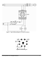
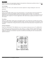
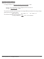
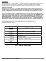
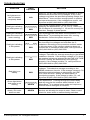
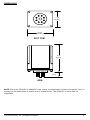
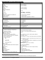
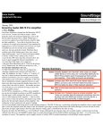
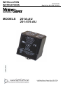
INSTALLATION
INSTRUCTIONS
201A-AU
201-575-AU
II_201A-AU_B1
MODELS
Revision B1
Rapid City, SD, USA, 02/2010
222
Disk
Drive,
Rapid
57701
2880 North
Plaza
Drive,
Rapid
City,City,
SouthSD
Dakota
57702
(800) 843-8848
www.symcom.com
(800) 843-8848
· (605) 348-5580
· fax (605) 348-5685
BE SURE POWER IS DISCONNECTED PRIOR TO INSTALLATION!
FOLLOW NATIONAL, STATE AND LOCAL CODES.
READ THESE INSTRUCTIONS ENTIRELY BEFORE INSTALLATION.
®
SymCom’s MotorSaver Model 201A-AU is an auto ranging plug-in voltage / phase monitor
designed to protect 3-phase motors regardless of size. It is used on 190-480VAC (475-600 for
Model 201-575-AU), 50/60 Hz motors to prevent damage caused by single-phasing, low voltage,
high voltage, phase reversal, or voltage unbalance conditions.
CONNECTIONS
1.
Locate a convenient location in or near the motor control panel. If the location is wet or
®
dusty, the MotorSaver should be mounted in a NEMA 4 or 12 enclosure.
2.
Mount an 8-pin socket to the motor control back panel (SymCom P/N OT08-PC, sold
separately, is required for UL rating).
3.
Connect L1, L2 and L3 (terminals 3, 4 & 5 on the relay socket) to the LINE SIDE of the
motor starter as shown in Figure 1.
4.
Connect the output relay to the circuitry to be controlled. For motor control, connect the
normally open contact in series with the magnetic coil of the motor starter, and for alarm
operation, connect the normally closed contact in series with the control circuit. See Figure
1 for details.
5.
Plug the MotorSaver into the socket.
®
© 2010 SymCom, Inc. All Rights Reserved
2
Figure 1: Typical Wiring Diagram for Control and Alarm
Figure 2: Pin-Out Diagram
© 2010 SymCom, Inc. All Rights Reserved
3
SETTINGS
Rotate the knobs to the appropriate setting for the application following the guidelines below. Do not
apply excessive force when adjusting settings.
Line Voltage
Rotate the VOLT ADJ. (VAC) knob to the nominal 3-phase line voltage feeding the motor to be
protected.
Restart Delay
Rotate the RESTART (SEC) knob to the desired position. The restart delay is the time between the
MotorSaver® measuring acceptable voltage and closing its output contacts. For compressor
applications, the restart delay should be set for the approximate time it takes for the head pressure to
bleed off of the compressor. For other applications, the restart delay is typically set between 10 and
20 seconds.
Trip Delay
Rotate the TRIP DELAY (SEC) knob to the desired setting. This setting does not affect the trip delay
on single-phasing faults (See SPECIFICATIONS Table). Typically, the trip delay is set between 1 and
5 seconds. In areas where voltage fluctuations are frequent, the trip delay may be set greater than 10
seconds.
Voltage Unbalance
Rotate the UNBALANCE TRIP (NEMA%) knob to the desired unbalance trip level. The NEMA MG1
standard does not recommend operating a motor above 1% voltage unbalance without derating the
motor. The NEMA MG1 standard also recommends against operating a motor above a 5% voltage
unbalance under any circumstances. SymCom recommends consulting the motor manufacturer for
specific tolerances.
Figure 3: Adjustment Knobs
© 2010 SymCom, Inc. All Rights Reserved
4
Calculating Voltage Unbalance
NEMA MG1 Unbalance Formula
% Voltage Unbalance = Maximum Deviation from the Average x 100%
Average
Example: The measured line-to-line voltages are 203, 210, and 212.
Average = 203 + 210 + 212 = 208.3
3
The maximum deviation from the average is the largest difference between the average voltage
(208.3) and any one voltage reading.
208.3 - 203 = 5.3
210 - 208.3 = 1.7
212 - 208.3 = 3.7
The maximum deviation from the average is 5.3.
% voltage unbalance = 5.3 x 100 = 2.5% unbalance
208.3
© 2010 SymCom, Inc. All Rights Reserved
5
OPERATION
®
After applying power to the MotorSaver , the green RUN light will blink during the restart delay. After
®
the restart delay time has expired, the MotorSaver will energize its output contacts (open the
normally closed and close the normally open contacts) and the RUN light will turn solid green.
Automatic Reset Mode
Set the RESTART (SEC) knob to the desired restart delay time. Apply 3-phase power to the motor.
The MotorSaver’s green RUN light will blink during the restart delay. Once the restart delay time has
expired, the MotorSaver® will energize its output contacts and the green RUN light will illuminate.
Manual Reset Mode
Once power has been applied to the MotorSaver®, set the RESTART (SEC) knob to M to operate in
®
manual reset mode. When the MotorSaver trips on a fault, the red STATUS light will display the fault
code until the condition clears and the unit is reset by turning the RESTART (SEC) knob away from
the M position until the STATUS light turns green. The RESTART (SEC) knob can then be turned
back to the M position, requiring a manual reset after the next fault occurs. If power is lost before the
MotorSaver® is reset, the fault code will again be displayed once power is reapplied. This allows for
identification of the last fault even after power conditions have returned to normal.
If the contacts do not energize and the RUN light does not turn solid green, see the
TROUBLESHOOTING section.
STATUS
GREEN
GREEN
GREEN
RED
RED
RED
RED
INDICATOR LIGHT
RUN
RESTART DELAY (Automatic Reset Mode)
MANUAL RESET REQUIRED (Manual Reset Mode)
REVERSE PHASE
UNBALANCE / SINGLE PHASE
HIGH VOLTAGE
LOW VOLTAGE
Table 1: Diagnostic Indicator Lights
© 2010 SymCom, Inc. All Rights Reserved
6
TROUBLESHOOTING
SYMPTOM
No lights are on the unit seems
completely dead
Red light is blinking
(on initial power-up)
Red light is blinking
(after the motor has
been running)
Red light is blinking
in this pattern
Red light is blinking
in this pattern
Red light is on
steady
LIGHT
PATTERN
SOLUTION
N/A
Verify L1, L2 & L3 are connected to terminals 3, 4 & 5.
Measure the three line-to-line voltages. If any of the
voltages are below the specified operating voltage, the
®
MotorSaver does not have enough power to operate
its internal electronics. If the voltages are correct, call
SymCom at (800) 843-8848 or (605) 348-5580.
RED
RED
RED
RED
RED
Turn off the 3-phase power. Swap any two leads
®
powering the MotorSaver (L1, L2, or L3). There is a
50-50 chance of connecting L1, L2 and L3 correctly the
first time. Reapply 3-phase power.
The incoming lines have been reverse-phased. The
®
MotorSaver is preventing the motor from running
backwards. Correct the phase sequence.
The voltage is unbalanced or single-phased. Measure
the incoming line voltages and calculate the %
unbalance according to the procedure outlined earlier
in this document. If the voltage unbalance does not
exceed the % unbalance reset value, call SymCom at
(800) 843-8848 or (605) 348-5580.
The voltage is high. Measure the three line-to-line
voltages. Calculate the average according to the NEMA
unbalance formula. If the average voltage is 7% above
the nominal voltage as selected by the LINE VOLTAGE
®
ADJUST setting, the MotorSaver is functioning
properly. If the voltage is within 7%, call SymCom at
(800) 843-8848 or (605) 348-5580.
The voltage is low. Measure the three line-to-line
voltages. Calculate the average according to the
NEMA unbalance formula. If the average voltage is 7%
below the nominal voltage as selected by the LINE
®
VOLTAGE ADJUST setting, the MotorSaver is
functioning properly. If the voltage is within 7%, call
SymCom at (800) 843-8848 or (605) 348-5580.
®
Green light blinks
and motor is not
running
Green light is on
steady, but motor
does not start
GREEN
The MotorSaver is timing through the restart delay
and will energize its contacts when finished, or the
®
MotorSaver is in manual reset mode and requires a
manual reset to energize its contacts.
®
GREEN
© 2010 SymCom, Inc. All Rights Reserved
The MotorSaver is in run mode. Ensure other control
devices are allowing the motor to start. Check control
circuit for loose wires or malfunctioning switches.
7
DIMENSIONS
1.75
(44.55)
2.375
(60.331)
BOT TOM
3.15
(80.01)
.5
(12.7)
SIDE
NOTE: Use of the OT08-PC or RB08-PC octal socket, manufactured by Custom Connector Corp., is
required for the MotorSaver to qualify as a UL Listed device. The OT08-PC is 35mm DIN rail
compatible.
© 2010 SymCom, Inc. All Rights Reserved
8
MOTORSAVER® 201A-AU SPECIFICATIONS
Functional Characteristics
Low Voltage
Trip
Reset
High Voltage
Trip
Reset
Voltage Unbalance
Trip
Reset
Trip Delay
High/Low Voltage and Unbalance
Single-Phasing
Restart Delay
90% of setting
93% of setting
110% of setting
107% of setting
2-8%
Trip setting - 1% (5-8%)
Trip setting - 0.5% (2-4%)
1-30 seconds, adjustable
1 second, fixed
1-500 seconds, adjustable; Manual
Input Characteristics
Line Supply Voltage
201A-AU
201-575-AU
Frequency
190-480VAC
475-600VAC
50/60Hz
Output Characteristics
Output Contact Rating
Pilot Duty
General Purpose
480VA @ 240VAC
10A @ 240VAC
General Characteristics
Environmental
Ambient Operating Temperature 1
Relative Humidity
Maximum Input Power
Standards Passed
Electrostatic Discharge (ESD)
Radio Frequency Immunity, Radiated
Fast Transient Burst
Surge Immunity
IEC
ANSI/IEEE
Hi-Potential Test
Safety Marks
UL listed (OT08 octal socket required)
CE
Dimensions
Weight
Enclosure
Mounting Method
Wire Gauge
Terminal Torque for P/N OT08 Socket
1
-40° to 70°C (-40° to 158°F)
10-95%, non-condensing per IEC 68-2-3
5W
IEC 61000-4-2, Level 3, 6kV contact, 8kV air
150 MHz, 10V/m
IEC 61000-4-4, Level 4, 4kV input power and controls
IEC 61000-4-5, Level 4, 4kV line-to-line; Level 4, 4kV
line-to-ground
C62.41 Surge and Ring Wave Compliance to a level of
6kV line-to-line
Meets UL508
(2 x rated V +1000 V for 1 minute)
UL508 (File #E68520)
IEC 60947-6-2
1.750” H x 2.375” W x 4.125” D (with socket)
9 oz.
Polycarbonate
Plugs into OT08 Socket
12-22 AWG Solid or Stranded
12 in. - lb
The ambient air temperature is the air temperature directly surrounding the product.
© 2010 SymCom, Inc. All Rights Reserved
9
NOTES
© 2010 SymCom, Inc. All Rights Reserved
10
NOTES
© 2010 SymCom, Inc. All Rights Reserved
11
For warranty information, please see Terms and Conditions at
www.symcom.com
Visit us at www.symcom.com to see
our complete product listing!
Need something special?
Contact SymCom today
for your custom solution!
800-843-8848
© 2010 SymCom, Inc. All Rights Reserved
12