1
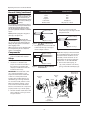
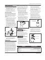
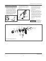
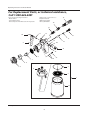
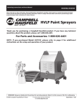
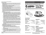
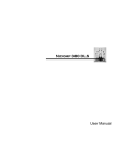
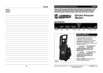
HVLP Spray Gun
Operating Instructions & Parts Manual
Please read and save these instructions. Read carefully before attempting to assemble, install, operate or maintain the product described. Protect yourself and
others by observing all safety information. Failure to comply with instructions could result in personal injury and/or property damage! Retain instructions for
future reference.
HVLP Spray Gun
Attention: Campbell Hausfeld recommends that servicing other than that shown in the instruction manual should be performed by an
authorized service facility.
Description
High volume, low pressure (HVLP)
paint sprayers are designed to deliver
a fine finish with low overspray. The
sprayer can be used to apply various
acrylics, stains, sealers, lacquers, latexes,
and primers. This unit can be used for
painting cabinets, furniture, machinery,
equipment, walls and trim work. Sprayers of this type are not recommended
for automotive final coat. This portable
unit is an ideal alternative to conventional spray guns. The HVLP’s high transfer
efficiency provides professional results
with much less material waste and environmental contamination than other
conventional spray painting systems.
Quick Connect Fitting
Air Flow Control
Oval To Round
Pattern Adjustment
Material Flow
Control Knob
Locking Lever For
Quick-Release Paint Cup
1 Quart Cup
Unpacking
When unpacking the sprayer, inspect
carefully for any damage that may
have occurred during transit. Make
sure any loose fittings, bolts, etc., are
tightened before putting sprayer into
service. Each sprayer has been tested
before shipment.
NOTE: The packing nut may need
additional adjustment due to the
packing material relaxing during
shipment.
The fluid used for testing the sprayer
has been drained, but some of this fluid
will remain in the spray gun. This fluid
should be flushed from the spray gun to
prevent contamination of the coating
material. Use a solvent compatible with
the coating to be sprayed.
Table Of Contents
Description . . . . . . . . . . . . . . . . . . . . 1
Unpacking. . . . . . . . . . . . . . . . . . . . . 1
General Safety Information. . . . . . . 1
Setup . . . . . . . . . . . . . . . . . . . . . . . .2-3
Operation . . . . . . . . . . . . . . . . . . . . . 4
Maintenance. . . . . . . . . . . . . . . . . .4-5
Troubleshooting . . . . . . . . . . . . . . . . 6
Warranty. . . . . . . . . . . . . . . . . . . . . 10
Figure 1 - Features
General Safety
Danger means a
hazard that will cause
death or serious injury if the warning is ignored.
!
DANGER
! WARNING Warning means a
hazard that could cause death or serious
injury if the warning is ignored.
Caution means a
hazard that may cause
minor or moderate injury if the warning is
ignored. It also may mean a hazard that will
only cause damage to property.
!
CAUTION
Notice means any
additional
information pertaining to the product or its
proper usage.
NOTICE
Read all instructions and safety
precautions before operating the unit.
Risk
! WARNING of fire
or explosion! Solvent and
paint fumes can explode or
ignite, causing severe injury
and property damage.
Paints and solvents containing
HALOGENATED HYDROCARBONS can react
explosively with aluminum. Always check
the product’s label before using these
materials in the unit.
Make sure the room is well-ventilated.
Avoid all ignition sources, such as static
electricity sparks, open flames, hot objects,
sparks from connecting and disconnecting
power cords, and working light switches.
Follow the material and solvent
manufacturers’ safety precautions and
warnings. Do not use liquids with flash
points less than 100 degrees Fahrenheit (38
degrees Celsius).
Do not carry TURBINE while spraying.
Keep the turbine at the maximum distance
from the spraying area.
Static electricity can be produced by
HVLP spraying. Make sure any electrically
conductive object being sprayed is
grounded to prevent static sparking. The
sprayer is grounded through the electric
cord. If an extension cord is necessary, the
cord must be a grounded, 115 volt, three
wire type cord.
IN206701AV 9/07
©2007 Campbell Hausfeld/ Scott Fetzer
For parts, product & service information
visit www.chpower.com
Operating Instructions and Parts Manual
General Safety (continued)
SPRAYING MATERIAL
NEEDLE/NOZZLE
Acrylics
Stains
Sealers
Lacquers
Latex Paint
Oil Base Paint
All purpose or Thin
Thin
Thin
Thin
All purpose
All purpose or Thick
Hazardous vapors: Paints,
solvents, insecticides, and
other materials may be
harmful if inhaled, causing
severe nausea, fainting, or
poisoning.
Use a respirator or mask whenever there is
a chance that vapors may be inhaled. Read
all instructions with the mask to ensure
that the mask will provide the necessary
protection against the inhalation of harmful
vapors.
Chart 1 - Material Needle/Nozzle Combination
4. The thick material needle and
nozzle have 2 groove rings as shown
in Figure 4 below.
(1) Groove Ring
NEVER point the spray gun at any part of
the body, or at anyone else.
(2) Groove Rings
!
CAUTION
Tipping the gun
causes the gun to clog. Dried spray material
also clogs the pressure delivery tube and
fittings. The spray gun does not function
when clogging occurs.
When not in use, be sure to disconnect the
hose and place the gun on a solid, level
surface to avoid tipping.
(1) Groove Ring
Figure 2 - Thin Material Needle And
Nozzle Kit
3. The all purpose material needle and
nozzle have three groove rings as
shown in Figure 3 below.
Components
Setup
IMPORTANT: The needle and nozzle
are a matched assembly. It is very
important that both the needle and
nozzle are correctly selected and
installed. The needle/nozzle kits are
identified by groove rings machined
into both the needle, and the nozzle.
Make sure that the number of rings
in the nozzle and the needle match.
Failure to match these two components
properly results in poor finish quality.
2. The thin material needle and nozzle
have a single groove ring as shown
in Figure 2 below.
Figure 4 - Thick Material Needle Kit
Note: The all-purpose material needle
kit is included with the unit. The thick
and thin material needle kits are not
included, however these kits can be
purchased from the retail outlet that
sold the unit or call 1-800-626-4401.
(3) Groove Rings
(1) Gun - fully assembled, with all
purpose needle/nozzle installed
NEEDLE AND NOZZLE ASSEMBLY
1. Use Chart 1 to determine the
proper size nozzle and needle for
the material to be applied. The
all purpose needle and nozzle are
installed at the factory.
(2) Groove Rings
(3) Groove Rings
Figure 3 - All Purpose Material Needle
And Nozzle Kit
5. Remove the retaining ring, air
cap, nozzle, material control knob,
spring, and needle assembly (Fig. 5).
Material Flow
Control Knob
Air Flow
Ring
Retaining
Ring
Nozzle
Spring
Needle
Assembly
Air Cap
Wrench
(located inside
storage
compartment)
Figure 5 - Needle/Nozzle Installation
www.chpower.com
2
Operating Instructions and Parts Manual
Setup (continued)
6. Install the appropriate needle/nozzle
assembly selected for the material to
be sprayed (Fig. 2, 3 & 4 ).
7. Reassemble the needle assembly,
spring, material control knob,
nozzle, air cap, and retainer ring.
ADJUSTING PACKING
Occasionally the packing nut, located
forward of the trigger assembly, will
require adjustment. The packing nut
will also require adjustment when the
needle/nozzle assembly is changed
(Figure 6).
1. Turn the material flow control knob
clockwise at least 3/4 of the way in.
2. Tighten the packing nut with
the wrench by turning the nut
clockwise until the needle will
not return to the closed position
when the trigger is released. Do
not overtighten the packing nut.
To properly adjust the packing, the
nut should be tightened no further
than is required to stop the needle
from returning. (See Figure 6).
Material Flow
Control Knob
NOTICE: Some latex finishes are very
thick and require the greatest amount
of thinning and mixing. A latex paint
conditioner can be added to the
paint to improve spray performance
(available at most home centers).
1. Strain paint before spraying.
Unstrained paint may affect
material flow and spray pattern.
When spraying thin materials such
as lacquer or stains, consult with
the material supplier for the proper
strainer mesh number.
2. Pour material into the paint cup.
Fill the material cup only 1/2 to 3/4
full if thinning of the material is
required. (See Figure 7). Refer to
the material chart below for proper
thinning instructions.
b. Estimate the time interval between
each of the first three drips of
material. The time between the
first three drips of material will vary
depending on the thickness or the
“viscosity” of the material.
c. The material is adequately thinned if
the first three drips from the viscosity
stick are about one second apart.
d. As a general rule, if the time
between drips is more than one
second, the material is too thick.
Add thinning agent, stir thoroughly
and repeat the above procedure
until the proper viscosity is attained.
Viscosity Stick (Located
Inside The Storage
Compartment)
Figure 8 - Viscosity Stick
Figure 7 - Filling The Paint Cup
Follow the
material
manufacturer’s recommendation for the
proper thinning solvent.
NOTICE
Tighten
Packing
Nut
Figure 6 - Adjusting The Packing Nut
3. Loosen the packing nut (approx.
1/4 turn) until the needle returns
freely to the closed position.
Preparation
PREPARING TO SPRAY
Some manufacturers specify that their
materials should not be thinned. In
general, these instructions apply only
when a brush or roller is used. It may
be necessary to thin these materials if
they are to be sprayed. Check with the
paint supplier for specific details when
purchasing the material to be sprayed.
Be sure to stir the material thoroughly
after adding a thinning agent, and
before checking the viscosity. Failure to
properly mix the material results in a
poor finish.
3. Using the following procedure,
check the viscosity of the material
before locking the gun onto the
material cup (Figure 8).
4. To tighten and lock the cup, place
the retainer arms securely around
the retaining pins on the paint cup.
5. Move the locking lever clockwise to
the locked position. (See Figure 9).
Locking Lever
The viscosity stick
is located in the
storage compartment.
Retaining Arm
a. Dip the viscosity stick into the
material. As the viscosity stick is
removed from the material, the
material will initially run off the stick
as a stream. The material stream will
break up and begin to drip after
running off the stick for a short time.
Retaining Pin
NOTICE
MATERIAL
Figure 9 - Locking The Cup
PERCENT REDUCED
Acrylics.............................................................. Follow Manufacturer’s Instructions
Stains ......................................................................................No Thinning Required
Clear Sealers ...........................................................................No Thinning Required
Lacquers ........................................................... Follow Manufacturer’s Instructions
Oil-Base Paint ............................................................................................... 10 - 40%
Latex Paints .................................................................................................. 15 - 20%
www.chpower.com
3
Operating Instructions and Parts Manual
CREAS
IN
Retaining
Ring
E
Preparation (continued)
6. Attach the air hose quick-connect
fitting to the gun.
The quick-connect
fitting outer sleeve is
spring loaded and must be pulled back to
attach or remove it from the gun (See
Figure 10).
NOTICE
=
Operation
Always practice first. Make the gun
adjustments on a test surface such as
cardboard before spraying the project.
=
Vertical Pattern
Use right to left or
left to right strokes
=
Round Pattern
Stroke in any
direction
Figure 12 - Adjusting The Spray
Patterns “Type”
5. To adjust the material flow, turn the
material control knob clockwise to
decrease and counterclockwise to
increase. (See Figure 13).
The turbine air
hose can be used to
blow-dry those areas that are too heavily
coated, or slow in drying.
NOTICE
The air from the turbine is warm as a
result of normal operation. This can
affect the finish quality on hot dry
days due to premature drying of some
coatings such as lacquer. Retarding
agents can be added to the material
to resolve this condition. Consult the
material supplier for the proper retarding agent, and mixing procedures.
Maintenance
CLEANING
Make sure the room
D
EC
when using solvents. Dispose of all
materials properly, in accordance with all
local regulations.
R E AS
Figure 13 - Adjusting The Material Flow
Right
Reducing the air flow also reduces
overspray.
! WARNING is well ventilated
CREAS
IN
E
1. Keep the gun 4" - 9" from, and
parallel to the surface of the object
being sprayed. (See Figure 11). If
the material delivery is adjusted
for a small narrow pattern, it may
be necessary to move as close as 2"
from the work surface.
Horizontal Pattern
Use up and down
strokes
E
Figure 10 - Attaching The Air Hose
Figure 14 - Fine Pattern Adjustment
Spring
6. For fine pattern adjustment, turn
the air flow control knob clockwise
to decrease and counterclockwise to
increase air flow (See Figure 14).
1. Remove the material control knob,
spring, and needle. (Pull the trigger
to help remove the needle). NOTICE:
Removing the needle prior to
removing the nozzle will prevent
needle damage.
2. Using the supplied wrench, unscrew
and remove the retainer ring, nozzle,
and airflow ring (See Figure 15).
Wrong
Wrench
Figure 11 - Painting Strokes
2. Move the gun in a smooth even
stroke. Begin the stroke before
pulling the trigger and continue the
stroke after releasing the trigger.
3. For best results overlap each stroke
by 25 to 50%.
4. To adjust the spray pattern “type”,
turn the air cap to the desired
pattern position (See Figure 12).
Air
Flow
Ring
Material Flow
Control Knob
Retaining ring
Spring
Needle
Nozzle
Air Cap
Figure 15 - Preparation For Cleaning
www.chpower.com
4
Operating Instructions and Parts Manual
Maintenance (continued)
3. Place the parts and the paint cup in
a bucket or other suitable container.
Soak the parts in a suitable solvent,
or in soap and water if latex was
used (See Figure 16). To clean the
gun, flush a suitable cleaning solvent
through the material tube until the
solution begins to clear. Repeat the
procedure from the nozzle end of
the gun (See Figure 16).
4. Use the brush (saturated with solvent) between flushes to clean the
material tube and the nozzle (See
Figure 17).
Material
Tube
Cleaning
Brush
Figure 17 - Cleaning The Material Tube
Figure 16 - Cleaning The Spray Gun
Parts
Blow
dry
Blow
dry
Blow
dry
5. Reinstall the components in reverse
order of disassembly (See Figure
18). Always install nozzle before
installing the needle to prevent
needle damage.
6. When the gun and all parts are
thoroughly cleaned, use the turbine
hose to dry the parts and blow the
passages dry. Thorough drying of
the gun and all components prior to
reassembly prevents coating contamination during the next operation
of the unit, and inhibits oxidation
of internal gun components (See
Figure 18).
The four raised
knobs on the air flow
ring must be facing forward (toward the
nozzle) when assembled. (See Figure 18).
NOTICE
Blow dry
Air
Flow
Ring
Material Flow
Control Knob
Spring
Needle
Nozzle
Knob
(Forward)
See Note
Above
Blow
dry
Figure 18 - Blow Drying Components
www.chpower.com
5
Operating Instructions and Parts Manual
Troubleshooting Chart
Symptom
Possible Cause(s)
Corrective Action
No material flow
1. Clogged nozzle/air cap
2. Clogged cup pressure tube or fittings
1. Disassemble and clean
2. Disassemble and clean (a straight pin
can be used to clean fittings)
3. Disassemble and clean
4. Disassemble and clean gun, and check
valve
5. Inspect cup seal, cup cap, and clean or
replace as necessary
6. Strain paint
3. Clogged gun
4. Clogged material tube
5. Cup seal leaking
6. Material not properly mixed, or
improperly filtered
Slow material flow
1. Material too thick
2. Improper material adjustment
3. Wrong needle/nozzle
4. Air filter clogged
5. Material not properly mixed, or
improperly filtered
6. Material too cold
1. Clear material tube, gun, fittings, and
thin the material
2. Adjust material control knob
3. Refer to material application chart for
correct needle/nozzle
4. Remove and replace air filter
5. Strain paint
6. Raise material temp. to 60°F (15°C)
8. Damaged needle
9. Loose material control knob
10. Cup seal leaking
1. Check cup gun and replace damaged
parts
2. Adjust packing nut
3. Remove and replace
4. Remove and replace
5. Tighten
6. Tighten
7. Refer to material application chart for
correct needle/nozzle
8. Replace
9. Properly adjust by turning clockwise
10. Clean and dry before use
Spray will not shut off
1. Dirty needle
2. Packing too tight
3. Loose material control knob
1. Clean or replace needle
2. Adjust packing nut
3. Tighten
Pulsating spray
1. Cup seal or check valve leaking
2. Packing improperly adjusted
1. Disassemble and clean
2. Adjust packing nut, or replace packing
3. Tighten
4. Tighten
5. Tighten
6. Replace
7. Strain paint
Material leak
1. Cup or gun damaged
2. Loose packing
3. Worn or damaged packing
4. Worn or damaged cup seal
5. Loose cup fittings
6. Loose nozzle
7. Wrong needle/nozzle assembly
3. Loose fittings on cup or gun
4. Loose air cap retainer ring
5. Loose nozzle
6. Damaged air flow ring
7. Material not properly mixed, or
improperly filtered
Excessive overspray
1. Material too thin
2. Excessive air flow
3. Wrong needle/nozzle
4. Gun too far from project
5. Spray blown by wind
6. Excessive material flow
7. Material not properly mixed, or
improperly filtered
www.chpower.com
6
1. Check material viscosity (add nonthinned material)
2. Adjust air flow
3. Wrong needle/nozzle assembly
4. Move gun closer to surface
5. Move to an area without wind
6. Adjust material flow control knob
7. Strain paint
Operating Instructions and Parts Manual
Troubleshooting Chart
Symptom
Spray not uniform
(spitting)
Possible Cause(s)
Corrective Action
1. Material too thick
1. Check material viscosity (Thin
per instructions)
2. Change to proper needle/nozzle
3. Tighten cup, replace seal or check
valve
4. Adjust or replace packing
5. Strain paint
2. Wrong needle/nozzle assembly
3. Cup seal leaking
4. Loose packing
5. Material not properly mixed, or
improperly filtered
Poor pattern
1. Material buildup on nozzle or air cap
2. Worn nozzle/needle
3. Clogged air cap
4. Material not properly mixed, or
improperly filtered
1. Clean nozzle and air cap
2. Replace
3. Clean
4. Strain paint
Overheating
1. Clogged filter
1. Replace
Poor air flow
1. Clogged filter
2. Air flow control improperly adjusted
1. Replace filter
2. Adjust air flow control
Spray tip clogs
1. Improper material flow adjustment
2. Cup seal leaking
3. Wrong needle/nozzle
1. Adjust material control
2. Replace cup seal
3. Change to proper needle/nozzle
Troubleshooting Chart - Finish Quality
Symptom
Possible Cause(s)
Orange Peel
(Rough rolling
appearance similar
to an actual orange
peeling)
1. Material drying too fast
Runs and sags
1. Material too thin
2. Moving gun too slow
3. Excessive material flow
Corrective Action
1. Use a slower solvent, or add a retarding agent
2. Move gun closer to surface
3. Thin material per thinning instructions
2. Gun too far from surface
3. Material too thick
1. Add material to increase thickness
2. Move gun more quickly
3. Turn material control knob clockwise
to reduce flow
4. Move gun further from surface
4. Gun too close to surface
Pin-holing and solvent
pops
1. Apply material in lighter coats, allowing solvents time to evaporate
2. Possible bad material
3. Thoroughly clean all parts
1. Trapped solvents
2. Pigment settling
3. System contamination
Fish eye
1. Possible silicone contamination
1. Use solvent to clean all parts and
projects
Blistering
1. Moisture in/on surface
2. Incompatible top coats or undercoats
1. Dry surface
2. Make sure coatings are compatible
Lumpy, coarse surface
1. Dirt on surface
1. Thoroughly clean surface
Mottled surface finish
1. Too much thinner
2. Poor spray technique
1. Reduce thinner
2. Refer to “Operation” for spraying
instructions
NOTICE:
• Weather conditions can cause unsatisfactory results when spraying some coatings.
• High humidity prolongs set, and cure times.
• High temperatures decrease set, and cure times.
• Cold temperatures extend set, and cure times.
• Variations in temperature, and humidity can cause variations in finish quality.
• Coating manufacturers can recommend additives to resolve some of these problems, and should be contacted for
assistance with particular problem resolutions.
www.chpower.com
7
Operating Instructions and Parts Manual
For Replacement Parts, or technical assistance,
Call 1-800-626-4401
Address parts correspondence to:
Campbell Hausfeld
100 Production Drive
Harrison, OH 45030
Please provide following information:
-Model number
-Serial number (if any)
-Part descriptions and number as shown in parts list
15
14
13
11
10
12
16
17
19
9
20
18
21
22
8
23
24
7
6
3
5
4
2
1
25
www.chpower.com
8
Operating Instructions and Parts Manual
Replacement Parts List
Ref
No.
1
2
3
4
5
Description
Canister assembly (as shown)
■ Check valve
■ Canister seal kit (Includes 3)
■ Pressure tube
Retainer ring
6
7
7
9
10
11
12
13
14
15
Qty
SK205800AJ
HV004400AV
SK206401AJ
SK105100AJ
HV000901AV
1
1
1
1
1
HV011000SV
See chart below
HV001201AV
✦❉
✦
1
1
1
1
1
✦
▲
HV003500AV
HV002200AV
MP310600AJ
1
1
1
1
1
HV003400SV
HV002900AV
See chart below
▲
▲
1
1
1
1
1
▲❉
✦
HV003200SV
HV002800SV
DH077900AV
1
1
1
2
1
Description
Part Number
Qty
Canister assembly (Includes items 2-4)
Trigger assembly (Includes items 9-11 & 22)
Air flow control knob assembly (Includes items 12, 19-21)
Gun body assembly (as shown, includes 9-13, & 16-24)
SK205800AJ
SK206100AJ
SK206200AJ
SK600000AJ
1
1
1
1
Air cap kit
Nozzle
Air flow ring
Trigger
E-ring
Trigger pin
Retaining ring
❉ Male quick connect fitting
Quick connect fitting
Hose
16
17
18
19
20
21
22
23
24
25
Part Number
Material flow control knob
Spring
Needle
O-ring
O-ring
Air control valve
E-ring
❉ Packing nut
❉ Packing
Canister
Replacement Parts Kit
Ref
No.
■
✦
▲
❉
Note:
Air Cap Kit includes #5, 6 & 8
Air Cap only (guns with Campbell Hausfeld embossed in handle)
HV000801AV
Needle/Nozzle Set
CH Embossed Gun
Smooth Handle Gun
Thin Material
HV7005
MP3018
All-Purpose
HV7004
MP3017
Thick Material
HV7006
MP3019
www.chpower.com
9
Operating Instructions and Parts Manual
Limited Warranty
1.DURATION: From the date of purchase by the original purchaser as follows: Standard Duty Paint Application Systems and
all Paint Application Accessories - 1 year, Serious Duty Paint Application Systems - 3 years, Extreme Duty Paint Application
Systems - 5 years.
2.WHO GIVES THIS WARRANTY (WARRANTOR): Campbell Hausfeld/A Scott Fetzer Company, 100 Production Drive, Harrison,
Ohio, 45030, Telephone: 1-800-626-4401.
3.WHO RECEIVES THIS WARRANTY (PURCHASER): The original purchaser (other than for purposes of resale or rental) of the
Campbell Hausfeld Product.
4.WHAT PRODUCTS ARE COVERED BY THIS WARRANTY: All non-compressor driven paint application systems, HVLP spraying
systems, and paint application accessories supplied or manufactured by the Warrantor.
5.WHAT IS COVERED UNDER THIS WARRANTY: Defects in material and workmanship which occur within the duration of the
warranty period. Warrantor will also cover normal wear items for a period of thirty days from the date of original purchase
against defects in material and workmanship. These wear items are: HVLP-filters, motor brushes, gun packing, gun canister
seal, gun check valve and gun air flow ring; Airless-inlet valve, outlet valve, gun valve, filters, tips, all seals and o-rings.
6. WHAT IS NOT COVERED UNDER THIS WARRANTY:
A. Implied warranties, including those of merchantability and FITNESS FOR A PARTICULAR PURPOSE ARE LIMITED FROM
THE DATE OF ORIGINAL PURCHASE AS STATED IN THE DURATION. If standard duty product is used for commercial or
industrial purposes, the warranty will apply for ninety (90) days from the date of original purchase. If product is used
for rental purposes, the warranty will apply for ninety (90) days from the date of original purchase. Some states do not
allow limitation on how long an implied warranty lasts, so the above limitations may not apply to you.
B. ANY INCIDENTAL, INDIRECT, OR CONSEQUENTIAL LOSS, DAMAGE , OR EXPENSE THAT MAY RESULT FROM ANY
DEFECT, FAILURE, OR MALFUNCTION OF THE CAMPBELL HAUSFELD PRODUCT. Some states do not allow the exclusion
or limitation of incidental or consequential damages, so the above limitation or exclusion may not apply to you.
C. Any failure that results from an accident, purchaser’s abuse, neglect or failure to operate products in accordance with
instructions provided in the owner’s manual(s) supplied with product. Accident, purchaser’s abuse, neglect or failure
to operate products in accordance with instructions shall also include the removal or alteration of any safety devices. If
such safety devices are removed or altered, this warranty is void.
D. Normal adjustments which are explained in the owner’s manual(s) provided with the product.
E. Items or services that are normally required to maintain the product: HVLP-filters, motor brushes, gun packing, gun
canister seal, gun check valve and gun air flow ring; Airless-inlet valve, outlet valve, gun valve, filters, tips, all seals and
o-rings., or any other expendable part not specifically listed, will only be covered for thirty days from date of original
purchase.
7. RESPONSIBILITIES OF WARRANTOR UNDER THIS WARRANTY: Repair or replace, at Warrantor’s option, products or
components which are defective, have malfunctioned and/or failed to conform within duration of the warranty period.
8. RESPONSIBILITIES OF PURCHASER UNDER THIS WARRANTY:
A. Provide dated proof of purchase and maintenance records.
B. Deliver or ship the Campbell Hausfeld product or component to the nearest Campbell Hausfeld Authorized Service
Center. Freight costs, if any, must be borne by the purchaser.
C. Use reasonable care in the operation and maintenance of the products as described in the owner’s manual(s).
9. WHEN WARRANTOR WILL PERFORM REPAIR OR REPLACEMENT UNDER THIS WARRANTY:
A. Repair or replacement will be scheduled and serviced according to the normal work flow at the servicing location, and
depending on the availability of replacement parts.
B. If the purchaser does not receive satisfactory results from the Authorized Service Center, the purchaser should contact
Campbell Hausfeld (see paragraph 2)
This Limited Warranty applies in the U.S. and Canada only and gives you specific legal rights. You may also have other rights
which vary from state to state, or country to country.
www.chpower.com
10