1
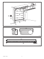
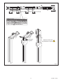
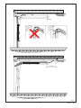
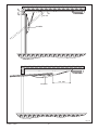
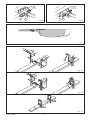
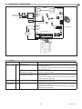
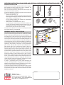
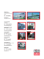
GLOBE
IP1839 - rev. 2006-07-24
I
Manuale di installazione
e manutenzione per porte
basculanti a molle e
sezionali.
GB
Installation and maintenance
manual for spring balanced
up and over door and
sectional overhead doors.
F
D
E
P
DITEC S.p.A.
Via Mons. Banfi, 3 - 21042 Caronno Pertusella (VA) - ITALY
Tel. +39 02 963911 - Fax +39 02 9650314
www.ditec.it - [email protected]
Manuel d’installation et
d’entretien pour portes
basculantes a ressort et
sectionneles.
Montage und
Wartungsanleitung für
Garagentorantriebe.
Manual de instalaciòn
y mantenimiento para
puertas basculante de
resortes y seccionales.
Manual de instalação e
manutenção para portas
basculantes a molas e
seccionadas.
3
7
4
6
12
2
8
1
RX - 4x0.5 mm²
11
TX - 4x0.5 mm²
5
9
10
9
Fig. 1
490
208
124
Fig. 2
30
500
3
20 10
Fig. 3
GLOBE - IP1839
2
X
370
X
4
205
X
3
370
X
2
1
205
Stringere!
Tighten!
Attenzione alle mani!
Pay attention to hands!
Fig. 4
3
GLOBE - IP1839
Fig. 5a
Fig. 5b
Fig. 5c
3000
GLOBEGF - GLOBEGA
Fig. 5d
Y
K
H
Fig. 5e
E
Fig. 5f
H E
1÷2 mm
GLOBE - IP1839
4
Fig. 6
M
30
10÷100
30
min. 680
Fig. 7a
5
GLOBE - IP1839
max. 210
30
min. 20
GLOBEC
min. 900
GLOBEC
Fig. 7b
GLOBE - IP1839
6
H E
1÷2 mm
Fig. 7c
max. 200
Fig. 7d
J
L
H
E
20÷100
M
G
Fig. 8a
TYPE
RE
DOOR
FACTU
OF
MANU
YEAR
Y
GE
SUPPL
VOLTA
ER
L NUMB
SERIA
Fig. 8b
7
GLOBE - IP1839
P
P
G
Fig. 8c
G
Fig. 8d
Fig. 9
GLOBESI
30
8
75
220
42
Fig. 10a
30
8
75
220
42
Fig. 10b
YES
NO
Fig. 10c
GLOBE - IP1839
8
GENERAL SAFETY PRECAUTIONS
MACHINERY DIRECTIVE
This installation manual is intended for professionally
competent personnel only.
Installation, electrical connections and adjustments must be
performed in accordance with Good Working Methods and in
compliance with applicable regulations. Before installing the
product, carefully read the instructions. Bad installation could
be hazardous.
The packaging materials (plastic, polystyrene, etc.) should not
be discarded in the environment or left within reach of children,
as these are a potential source of hazard. Before installing the
product, make sure it is in perfect condition.
Do not install the product in an explosive environment and atmosphere: gas or inflammable fumes are a serious hazard risk.
Before installing the motors, make all structural changes relating
t o safety clearances and protection or segregation of all areas
where there is risk of being crushed, cut or dragged, and danger
areas in general.
Make sure the existing structure is up to standard in terms of
strength and stability.
The motor manufacturer is not responsible for failure to use
Good Working Methods in building the frames to be motorised
or for any deformation occurring during use.
The safety devices (photocells, safety edges, emergency stops,
etc.) must be installed taking into account: applicable laws and
directives, Good Working Methods, installation premises, system
operating logic and the forces developed by the motorised door
or gate.
The safety devices must protect any areas where the risk exists
of being crushed, cut or gragged, or where there are any other
risks generated by the motorised door or gate. Apply hazard
area notices required by applicable regulations.
Each installation must clearly show the identification details of
the motorised door or gate.
Before making power connections, make sure the plate
details correspond to those of the power mains.
Fit an omnipolar disconnection switch with a contact opening
gap of at least 3 mm. Make sure an adequate residual current
circuit breaker and overcurrent cutout are fitted upstream of
the electrical system. When necessary, connect the motorised
door or gate to a reliable earth system made in accordance with
applicable safety regulations. During installation, maintenance
and repair, interrupt the power supply before opening the lid to
access the electrical parts.
To handle electronic parts, wear earthed antistatic conductive bracelets.
The motor manufacturer declines all responsibility in the event
of component parts being fitted that are not compatible with the
safe an correct operation.
For repairs or replacements of products only original spare parts
must be used.
The installer shall provide all information relating to automatic,
manual and emergency operation of the motorised door or gate,
and provide the user with operating instructions.
Pursuant to Machine Directive (98/37/EC) the installer who motorises a door or gate has the same obligations as a machine
manufacturer and shall:
- prepare technical documentation containing the documents
indicated on Schedule V of the Machine Directive;
(The technical documentation shall be kept and placed at
the disposal of competent national authorities for at least ten
years starting on the date of manufacture of the motorised
door);
- draw up the EC declaration of conformity according to Schedule II-A of the Machine Directive;
- affix the CE mark on the motorised door pursuant to para.
1.7.3 of Schedule I of the Machine Directive.
For more details, refer to the “Guidelines for producing technical
documentation” available on Internet at the following address:
www.ditec.it
OPERATING INSTRUCTIONS
Service class: 3 (minimum 30 cycles a day for 10 years or 60
cycles a day for 5 years)
Use: FREQUENT (for multi-family entrances or small condominiums with frequent car or pedestrian transit)
- The operating performance specifications refer to the recommended weight (about 2/3 of maximum allowed weight).
Use with maximum allowed weight could reduce the above
performance specifications.
- The service class, operating times and number of consecutive cycles are merely approximate. These have been
statistically determined in average conditions of use and
are not certain for each single case. They refer to the period when the product operates without the need for special
maintenance.
- Each automatic entrance features variable factors such as:
friction, balancing and environmental conditions that can
substantially change both the duration and operating quality
of the automatic entrance or part of its components (including
automatic system). It is up to the installer to adopt adequate
safety coefficients for each single installation.
MANUFACTURER’S DECLARATION
(Directive 98/37/EC, Schedule II, part B)
Manufacturer:
DITEC S.p.A.
Address:
via Mons. Banfi, 3
21042 Caronno P.lla (VA) - ITALY
Declares that the automatic system for spring balanced up and
over doors and sectional overhead doors of the GLOBE series:
- is manufactured to be incorporated into a machine or to be
assembled with other machines to make a machine considered
by Directive 98/37/EC;
- is in conformity with the conditions of the following other EC
directives:
R&TTE Directive 1999/5/EC,
Electromagnetic compatibility directive 89/336/EEC;
Low-voltage directive 73/23/EEC;
and further certifies that the machine shall not be commissioned
until the machine into which it is to be incorporated or of which
it is to become a component part has been identified and has
been declared in conformity with the conditions of the Directive
98/37/EC and the transposing national legislation.
Caronno Pertusella,
27-07-2000
17
Fermo Bressanini
(President)
GLOBE - IP1839
GB
GB 1.
TECHNICAL DETAILS
Power supply
Absorption
Fuse F1
Thrust
Max stroke
Max load
Opening speed
Closing speed
Service class
Intermittence
Temperature
Degree of protection
Control Panel
2.
GLOBE7
230 V~ / 50-60 Hz
0,7 A
F1,6A
500 N
2500 mm
7 m²
0,15 m/s (chain)
0,18 m/s (belt)
GLOBE7J
120 V~ / 50-60Hz
1,4 A
F3,15A
500 N
2500 mm
7 m²
0,15 m/s (chain)
0,18 m/s (belt)
0,10 m/s (chain)
0,12 m/s (belt)
3 - FREQUENT
S2 = 30 min / S3= 50%
-20° C / +55° C
IP10
70R
0,10 m/s (chain)
0,12 m/s (belt)
3 - FREQUENT
S2 = 30 min / S3= 50%
-20° C / +55° C
IP10
70R
REFERENCE ILLUSTRATIONS AND ACCESSORIES
3.2 Belt type GLOBE assembly (fig.5)
-
The given operating and performance features can only be guaranteed with the use of DITEC accessories and safety devices.
2.1 Standard installation references (fig. 1)
[1]
[2]
[3]
[4]
[5]
[6]
[7]
[8]
[9]
[10]
[11]
[12]
Radio
Drive unit
Retention bracket
Slide
Release cord
Guide
Guide coupling
Transmission
Photocells
Sensitive edge
Transmitter support
Connect the power supply to an omnipolar switch with contact opening
distance of at least 3 mm (not supplied by us) or by means of power plug.
Connection to supply mains must be carried out in an independent racewayseparatefromcontrolconnectionsandsafetydeviceconnections.
-
-
3.
-
Correct tensioning is achieved by leaving 1÷2 mm between
the spring retainer [E] and stop [H] to enable the spring [E]
to work in the best possible way.
Attention: over-tightening could affect proper operation of the
automatic system.
3.4 GLOBE installation (fig. 7-8)
-
Establish and trace the retention point of the guide on the
wall and ceiling (fig. 7a).
Attention: in the case of spring balanced up and over doors with
counterweights use GLOBEC (fig. 7b). With the off-board drive
unit, fit the guide to the wall using the transmission bracket (fig. 7c).
(fig. 7d) Fit the bracket [3] and secure using the screws
provided. Lift the unit and bend the brackets to measure (if
necessary eliminate the excess parts), then fasten to the ceiling.
Attention: (fig. 8) to fully open sectional doors with special
heights, the arm [M] can be shortened and the coupling point
[L] can be moved from 20 mm to 100 mm further in than [G].
If necessary, fit a shim [J] (not supplied by us, max 200 mm)
between the wall and the tightener [L]. This way the stroke of the
slide will be increased by exploiting all the available guide.
Manually release (see OPERATING INSTRUCTIONS)
and move the slide up to the closed door, then fit the retention bracket [G] on the top edge, possibly interposing
the supplied reinforcing angular [P] (fig.8c-d); afterwards,
re-lock the slide by moving the door manually.
(Fig. 9) Fit the stop in the guide and secure in the desired
opening position.
(Fig. 10) For stronger fastening the intermediate support
GLOBESI can be installed.
Battery kit
Adapter for up and over doors with counterweights
External release kit with cord and lock L=900 mm
Cord release device L= 2000 mm
Extension set for 1120 mm chain
Extension set for 1120 mm belt (for steel guide only)
Additional close stop
Intermediate support
Iron track L=3000 mm
Aluminium track L=3000 mm
INSTALLATION
3.1 Chain type GLOBE assembly (fig. 4)
-
Extend the chain.
Fit the coupling [1] as far as the guide stop. Fit the guide [2] as
far as the stop. Fit the coupling [3] as far as the guide stop [2].
Superimpose the guide [4] on the coupling [3], correctly fit
the transmission in the guide [4]: lift the guide as shown in
the detail to permit fitting the transmission.
Move the coupling [3] towards the transmission as far as
the guide stop [4].
Note: the guides must be fitted in a specific direction (see stops
[x] shown in illustration).
GLOBE - IP1839
(fig. 5a) Fit the belt to the transmission and slide.
(fig. 5b) Fit the belt stop as shown in the illustration.
(fig. 5c) Fasten the two ends of the belt to the release pin
by means of the couplings keeping to the pin direction
shown in the illustration.
(fig. 5d) Fit the drive pin (belt - transmission - slide) in the guide.
(fig. 5e) Pass the belt around the pulley and secure by
means of the pin [Y]. Fit the guide as shown in fig. 3, lock
in the drive unit as far as the stop and tighten screw [K].
(fig. 5f) Push the transmission towards the outside of the
guide and fasten the retention bracket to the wall.
3.3 Chain or belt tensioning (fig.6)
2.2 Accessories
BATK1
GLOBEC
ASB1
ASB2
GLOBEL
GLOBELV
GLOBEFM
GLOBESI
GLOBEGF
GLOBEGA
GLOBE10
230 V~ / 50-60 Hz
1,2 A
F1,6A
900 N
2500 mm
10 m²
0,12 m/s (belt + 71RC1)
0,15 m/s (chain)
0,18 m/s (belt)
0,10 m/s (chain)
0,12 m/s (belt)
3 - FREQUENT
S2 = 30 min / S3= 50%
-20° C / +55° C
IP10
71R (71RC1)
18
4.
ELECTRICAL CONNECTIONS
GB
OPEN
70R-71R
ANT
TRANSF.
24 V~ BAT
PRG
JR4
F1
BATK1
-M
Blu / Blue
+M
Motor
24V=
JR3
Luce di cortesia
Courtesy light
Nero / Black
ENC
SIG
SO
BIXMR2
Alimentazione
Power supply
JR2
COM
ON
OFF
1 2 3 4 5 6
POWER
ALARM
Only GLOBE10
SA
R1
TC
Passo-passo / Step by step
Sicurezza di inversione /
Reversal safety contact
Stop
Uscita / Output 24 V= / 0,3 A
Lampeggiante / Flashing light
Elettroserratura / Electric lock
Lampada / Lamp
1513 14 0 1 5 8 9
Only GLOBE10
ATTENTION: Make a jumper all the N.C. contacts if not used. Use only DITEC accessories and safety devices.
4.1 Controls
Control
Function
1
5
N.O.
1
8
N.C.
1
9
N.C.
Description
STEP-BY-STEP
With DIP1=OFF the closure of the contact activates the sequence:
open-stop-close-open.
Note: if automatic closing is enabled, the STOP is not permanent but at
a time that is set by TC.
OPEN WITH
With DIP1=ON and the automatic closure on, the closure of the contact
AUTOMATIC CLOSING
activates an opening operation.
OPEN WITHOUT
With DIP1=ON and TC=MAX, the closure of the contact activates an
AUTOMATIC CLOSING
opening operation.
With the automation idle, the closure of the contact performs the operation
opposite to that prior to the stop.
REVERSAL SAFETY CONTACT The closing of the contact during the closure manoeuvre causes the
movement to invert (re-opening).
STOP
The opening of the contact causes the movement to stop and the automatic closure to be disabled.
Resetting the command, the door remains still until a 1-5 command or
a radio command is received.
19
GLOBE - IP1839
GB
4.2 Output and accessories
Output
Value
1
0
+
-
24 V= / 0,3 A (nominal)
24 V= / 0,5 A (peak)
0
14
24 V= / 30 W max.
24 V= / 25 W
BAT
71R
0
15
24 V= / 1,2 A max
0
15
8,2 Ω / 5 W
1
13
5.
12 V / 15 W
24 V= / 3 W
Description
Accessories power supply. External accessories power supply output.
Flashing light (LAMPH). It is activated both on opening and on closing.
Courtesy light. It is activated for 3 minutes on every opening and closing command.
Battery operation. An optional battery kit is available (BATK1). With power supply
on, the batteries are kept charged. Without power supply, the panel is powered
by the batteries until power returns or until battery power falls below the safety
threshold. In this latter case, the control panel goes off.
Attention: to allow recharging, the batteries kit must always be connected to the
control panel. Periodically, verify the battery efficiency.
Note: the operating temperature of the rechargeable batteries is +5°C/+40°C
approximately. To ensure proper battery operation rooms should be airconditioned.
Electric lock. It is avtivated at each opening command given from closed door.
Electric lock. With a 12 V electric lock, connect the 8,2 Ω / 5 W resistor. It is
activated at each opening command given from closed door.
Open door light (analogic output). Light comes on and only goes off when door
is closed.
SETTINGS
5.1 Trimmer
Output
TC
120 s
MIN=0 s
MAX=disabled
R1
MIN
MAX=disabled
GLOBE - IP1839
Description
Automatic closing time. From 0 to 120 s, with TC<MAX.
With TC=MAX automatic closing is disabled.
The count starts with door stopped for time set with TC.
After the intervention of a safety (1-8), the countdown begins with the open door and lasts for the whole
time set with TC.
With TC=MAX or contact 1-9 open, automatic closing is disabled.
If disabled with 1-9, automatic closing is re-enabled, once the contact 1-9 has been closed again, only
after a control 1-5 or a remote control.
Obstacle thrust adjustment. The control panel is equipped with a safety device that stops the opening
operation and stops and inverts the closing operation in the presence of an obstacle.
With R1=MIN there is maximum obstacle sensitivity (minimum thrust).
With R1=MAX the detection function is deactivated (maximum thrust).
20
5.2 Dip-Switches
Description
OFF
DIP1 Control 1-5 function.
Step by step.
DIP2 Selection of direction.
Opening towards gearmotor.
DIP3 Disengagement on the closing 2 mm
stop with JR2=ON
Disengagement on the closing
stop with JR2=OFF
DIP4 State of door at start.
Indicates how the electronic panel
considers the door at the time of
start.
71R
DIP5 Electric lock release.
DIP6 Pre-flashing light.
GB
ON
Opening.
Closing towards gearmotor.
0,5 mm
Note: use this selection to prevent an incomplete closing of the sectional doors.
5 mm
Open.
With DIP1=OFF the first control 1-5 closes
the door.
With DIP1=ON the first control 1-5 opens
the door.
Disabled.
Disabled during opening.
Enabled only with automatic closure with
TC>3 s.
Close.
The first control 1-5 opens the door.
Note: automatic closing cannot be the first
control even if enabled.
Enabled.
Before opening from closed door, a thrust
is included in closing to facilitate electric
lock release.
Enabled for both opening and closing.
5.3 Jumpers
SO
Description
Safety operation.
JR2 Automation type.
OFF
ON
The opening of contact 1-8 with door The opening of contact 1-8 with door
stopped enables opening manoeuvre. In stopped prevents any operation.
the last 30 mm before closing stop, this
causes stop.
Up and over door with counterweight.
Sectional and up and over door with springs.
JR3 Maximum limit manoeuvering Normal closing force.
forces.
Note: use safety edge.
JR4 Built-in radio receiver.
Disabled.
Reduced closing force.
Enabled.
5.4 Signals
LED
POWER ALARM
SA
SIG
ON
Flashing
24 V= power supply.
Encoder / automation fault.
Indicates that at least one of the N.C. safety con- Upon starting the LED flashes indicating the count
tacts is open.
of the operations which have been carried out:
each quick flashing = 1000 operations
each slow flashing = 10000 operations
During radio transmitter enabling/storing phase. During radio transmission reception.
21
GLOBE - IP1839
GB
6.
RADIO
The control panel is equipped with a radio receiver with a frequency of 433.92 MHz. The antenna is a 173 mm long rigid wire.
The range of the radio receiver can be increased by connecting the external antenna on the flashing light or by installing a tuned
BIXAL antenna.
Note: use a RG58 (max 10 m) coaxial cable to connect the external antenna to the control panel.
Up to 200 transmitters can be memorised in the BIXMR2 memory.
Consult the L series remote control use instructions for the memorisation, cloning and cancellation of transmitters.
From one to four CH buttons of the same transmitter can be memorised on the control panel.
If just one transmitter CH button (any) is memorised command 1-5 (step-by-step/open) is performed.
If from two to four CH buttons of the same transmitter are memorised, the operations associated to the CH buttons are as follows:
CH1 = command 1-5 step-by-step/open ;
CH2 = partial opening command, causes the automation to open for 1 min.;
CH3 = courtesy light on/off command ;
CH4 = stop command, equal to the 1-9 impulsed command.
If the control panel is replaced, the BIXMR2 memory in use can be introduced to the new control panel.
Attention: the insertion and extraction of the BIXMR2 memory must be carried out in the absence of a power supply.
7.
STARTING
7.7
ATTENTION: The operations relating to 7.3 are performed without safety devices.
The trimmer can only be adjusted with the door stopped.
The 70R-71R electronic control panels do not need limit switches as they are provided with an encoder.
After each start, the electronic control panel is RESET and the first operation is carried out at reduced speed (automation
position learning).
The automation automatically slows down near the stops.
Make a jumper between the safety devices 1-8, 1-9.
Set the TC trimmer and R1 at maximum
Switch on power: have the closing and opening stops learnt with subsequent step-by-step controls.
Remove the jumpers and connect the safety devices (1-8) and the stop (1-9) and check correct operation.
If desired, adjust the automatic closing with the TC trimmer.
Set the thrust on obstacles with R1.
Check that the manoeuvering force and the scattering force between the door and the obstacle is lower than the values
indicated by standards EN12453 e EN12445.
Connect any accessories and check operation.
8.
MAINTENANCE SCHEDULE (every 6 months)
7.1
7.2
7.3
7.4
7.5
7.6
Without 230 V~ and battery power supply:
Clean and lubricate the moving parts (above all the internal edges of the guide where the trolleys run).
Check the stability of the automation system and check the tightness of all the screws.
Check battery efficiency.
Restore the 230 V~ and battery power:
Check the correct operation of the lock/release system (if fitted).
Check the stability of the door and that movement is smooth and friction-free.
Check the correct operation of all the control and safety functions.
Note: if the position of the door stops is changed or, more in general, after maintenance operations, interrupt and restore power
(batteries included if these are fitted) to repeat the learning process.
IMPORTANT: For the spare parts, refer to the spare parts list.
GLOBE - IP1839
22
8.
TROUBLESHOOTING
Problem
Possible cause
The automation does not open No power.
and close.
Accessories in short circuit.
(LED POWER ALARM flashing)
Line fuse burnt out.
The stop contact is open
The automation opens but does The safety contacts are open.
not close
(LED SA on).
The photocells (if fitted) are triggered.
(LED SA on).
Automatic closing does not work.
The automation fails to open. The automation is closed and the photocells (if
fitted) are operative.
(LED SA on).
Remote control does not work.
The external safety devices (if
fitted) fail to operate.
The automation opens/closes
for a short distance and then
stops.
The radio remote control has a
low range and does not work
with the automation in motion.
Remedy
Check that the control panel is on (the POWER
ALARM led must be on).
Disconnect all the accessories from the terminals
0-1 (24 V= are required) and reconnect these one
at a time.
Replace the fuse F1.
Check terminal 9 of the control panel
Check terminal 8 of the control panel.
Make sure the photocells are clean and working
properly.
Check the setting of the TC trimmer
Make sure the photocells are clean and working
properly.
See jumper SO.
Make sure the transmitters have been properly
stored on the built-in radio receiver. In case of
failure of the radio receiver built in the control
panel, the remote control codes can be accessed
by extracting the memory module.
Command devices faulty or connections Check opening by means of jumper 1-5 of the
interrupted.
terminal board control panel.
Wrong connections between the photocells and Connect the N.C. safety contacts together in series
the control panel
and remove any jumpers on the terminal board of
the control panel.
Encoder faulty.
Replace the encoder.
(LED POWER ALARM flashing).
Motor leads reversed.
Check the motor leads.
(LED POWER ALARM flashing).
There are frictions.
Manually make sure the automation is moving
freely.
Encoder not connected.
Check the connection.
False encoder contacts.
Clean the contacts by engaging and disengaging
the encoder plug on the contacts.
R1 set too low.
Check R1 adjustment.
Radio transmission is hampered by metal Install the antenna outside. Replace the batteries
frameworks and reinforced concrete walls.
of the transmitters.
23
GLOBE - IP1839
GB
OPERATING INSTRUCTION UP AND OVER AND SECTIONAL OVERHEAD DOOR AUTOMATION GLOBE
RELEASE INSTRUCTION
Perform the lock and release operations with the motor stopped.
Keep outside the range of action of the door. If released, the
door could move in an independent manner.
Note: to disconnect the door, interrupt the power supply and
disconnect the batteries (if fitted).
In case of an emergency, to open the up and over door manually,
perform the following operations:
- Internal cord release (fig. 1):
pull the cord with a downward movement until the lock release
lever is triggered. Keeping the cord pulled, open the door manually.
- ASB2 external cord release (fig. 2):
turn the release handle by 90° clockwise or anticlockwise
and open the door manually.
- ASB1 external cord release with key (fig. 3):
turn the key by 90° anticlockwise, remove the lock block and
pull the cord until the release lever trips and then move the
door slightly; fit the block in the lock and turn by 90° clockwise,
remove the key and open the door manually.
To restore motor operation, move the door manually: the release
mechanism fastens on automatically.
Fig. 1
Fig. 2
Fig. 3
The following precautions are an integral and essential part of the
product and must be supplied to the user. Read them carefully
as they contain important indications for the safe installation, use
and maintenace. These instruction must be kept and forwarded
to all possible future user of the system. This product must be
used only for that which it has been expressely designed. Any
other use is to be considered improper and therefore dangerous.
The manufacturer cannot be held responsible for possible damage caused by improper, erroneous or unresonable use. Avoid
operating in the proximity of the hinges or moving mechanical
parts. Do not enter the field of action of the motorised door or
gate while in motion. Do not obstruct the motion of the motorised door or gate as this may cause a situation of danger. Do
not lean against or hang on to the barrier when it is moving. Do
not allow children to play or stay within the field of action of the
motorised door or gate. Keep remote control or any other control
devices out of the reach of children, in order to avoid possible
involuntary activation of the motorised door or gate. In case of
breack down or malfunctioning of the product, disconnect from
mains, do not attempt to repair or intervene directly and contact
only qualified personnel. Failure to comply with the above may
create a situation of danger. All cleaning, maintenance or repair
work must be carried out by qualified personnel.
In order to guarantee that the system works efficiently and
correctly it is indispensable to comply with the manufacturer’s
indications thus having the periodic maintenance of the motorised door or gate carried out by qualified personnel.
In particular regular checks are recommended in order to verify
that the safety devices are operating correctly. All installation,
maintenance and repair work must be documented and made
available to the user.
TEAR OFF AND DELIVER TO USER
GENERAL SAFETY PRECAUTIONS
ON
OFF
Installer:
DITEC S.p.A.
Via Mons. Banfi, 3
21042 Caronno Pertusella (VA) - ITALY
Tel. +39 02 963911 - Fax +39 02 9650314
www.ditec.it - [email protected]
DITEC S.p.A.
Via Mons. Banfi, 3
21042 Caronno P.lla (VA)
ITALY
Tel. +39 02 963911
Fax +39 02 9650314
www.ditec.it
[email protected]
Quarto d’Altino (VE)
Caronno Pertusella (VA)
DITEC BELGIUM
LOKEREN
Tel. +32 (0)9 356 00 51
Fax +32 (0)9 356 00 52
www.ditecbelgium.be
DITEC DEUTSCHLAND
OBERURSEL
Tel. +49 61719141550
Fax +49 61719141555
www.ditec-germany.de
Lokeren
Oberursel
DITEC FRANCE
PALAISEAU
Tel. +33 1 64532860
Fax +33 1 64532861
www.ditecfrance.com
DITEC SVIZZERA
BALERNA
Tel. +41 91 6463339
Fax +41 91 6466127
www.ditecswiss.ch
Palaiseau
DITEC AMERICA
ORLANDO - FLORIDA - U.S.A.
Tel. +1 407 8880699
Fax +1 407 8882237
www.ditecamerica.com
DITEC CHINA
SHANGHAI
Tel. +86 21 62363861
Fax +86 21 62383863
www.ditec.cn
Orlando
Balerna