1
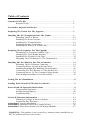
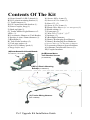
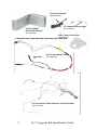
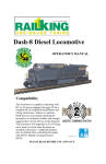
STEAM LOCOMOTIVE UPGRADE KIT
INSTALLATION MANUAL
3rd Edition
Compatibility
This Proto-Sound 2.0 Steam Locomotive Upgrade Kit is compatible with any
AC or DC Powered locomotive equipped with a DC can motor and motor
flywheel. The locomotive must be large enough to house the electronics. The
instructions herein are generic in nature and will not provide the installer with
specific installation details for specific locomotives. Consult the individual
item’s operator’s manual for specific instructions on how to disassemble the
locomotive prior to installing the upgrade kit.
WARNING: This product is not covered by a warranty unless installed by an
M.T.H. Authorized Conversion Center.
PLEASE READ BEFORE USE AND SAVE FOR REFERENCE
Table of Contents
Contents Of The Kit............................................................................................ 3
Required Tools...................................................................................... 6
Locomotive Inspection & Review.......................................................................7
Preparing The Tender For The Upgrade .......................................................... 8
Installing The Ps-2 Components Into The Tender........................................... 9
Mounting The Ps-2 Board..................................................................... 10
Installing The Proto-Coupler................................................................. 13
Installing The Tender Harness............................................................... 14
Soldering Speaker Connections............................................................. 17
Installing The Battery & Volume Pot.................................................... 18
Preparing The Locomotive For The Upgrade ...................................................20
Determing The Locomotive Motor Type...............................................21
Installing The Tach Reader Bracket...................................................... 21
Installing The Flywheel Tach Tape........................................................22
Mounting The Tach Reader To The Tach Bracket.................................23
Installing The Ps-2 Harness Into The Locomotive........................................... 24
Mounting The Ps-2 Harness Connector................................................ 24
Connecting Motor, Ground & Pickup Wires........................................ 25
Installing Headlight Into RailKing Steam Engines............................... 26
Connecting The Ps-2 Harness To The Smoke Unit.............................. 27
Connecting Power To The Constant Voltage Board............................. 28
Wire Management/Short Circuit Prevention......................................... 29
Testing The Ps-2 Installation ...............................................................................30
Loading Proto-Sound 2.0 Files Into Locomotive...............................................31
Proto-Sound 2.0 Operation Instructions............................................................34
Conventional Operation......................................................................... 34
Self-Recharging Battery.........................................................................40
Troubleshooting..................................................................................... 41
Service & Warranty Information.......................................................................44
Warranty Coverage & Service Options................................................. 44
Limited 90-Day Warranty..................................................................... 44
Addendum 1 Coupler Installation........................................................................ 45
Addendum 2 Optional Front Proto-Coupler Wiring............................................ 46
Addendum 3 Other Proto-Smoke Circuit Wiring Methods..................................47
WARNING: This product is not covered by a warranty unless installed by an
M.T.H. Authorized Conversion Center.
Contents Of The Kit
A) Proto-Sound 2.0 (PS-2) board (1)
B) PS-2 plastic mounting bracket (1)
C) Tender harness (1)
D) PS-2 metal heat sink bracket (1)
E) Proto-Coupler, long (1)
F) Back-up light (1)
G) Tender Marker Light Harness w/2
LEDs (1)
H) Locomotive Harness w/Tach Reader
I) Speaker, 4 ohm 50mm diameter (1)
J) Headlight (1)
K) Tach reader brackets (2)
L) Tach tape stripes (4)
M) AA Ni-Cd battery pack (1)
(Charge before use)
N) Screws M2 x 4 mm (2)
O) Screws 6/32 x 6 mm (3)
P) Nuts 6/32 (3)
Q) Screw 6/32 x 8 mm (1)
R) Plastic Wire Sleeve (for wire managment) (1)
S) Shrink tubing (1)
T) Foam tape (1)
U) Wire Ties (7) (6) 4”, (1) 7”
V) Inductor (1)
W) Headlight Grommet
X) Battery Recharging Port/Harness
Y) Battery Recharging Port Hardware
(2) Screws M3 x 12, (2) Nuts M3, (2) Spacers
Z) Locomotive Harness Spacer/Insulator
AA) Pittman Tach Reader Screws (2)
EE) Coupler Insulator
(A)Proto-Sound 2.0 Circuit Board
(AA)Pittman
Motor
E
Tach Bracket Screws
AE-0000010, AE-0000011
(IA-0000375)
(B)Ps-2 Plastic Mounting
Bracket (IH-0000391)
(C) Tender Wiring Harness
(BC-1000005)
Ps-2 Upgrade Kit Installation Guide
3
(E) Proto-Coupler
(DD-0000032)
(F) Tender Backup Light
(D) Ps-2 Metal
Heat Sink Bracket
(CF-0000030)
(IH-0000390)
(EE) Coupler Insulator
(ID-0000123)
(G) Tender Marker LEDs
(CC-0000062)
(H) Locomotive Wire Harness w/Tach Reader
(BC-1000003)
4
Ps-2 Upgrade Kit Installation Guide
(I) Speaker
(BF-0000034)
(N) M2 Screws
(O) 6/32 x 6mm Screws
(IA-0000058)
(IA-0000027)
(P) Nuts
(Q) 6/32 Screw x 8mm
(TP-M500075)
(IA-0000050)
(J) Locomotive Headlight
(CA-00000078)
(K) Tach Reader Brackets
(R) Plastic Wire Sleeve
Pittman
(IH-0000154)
Mabuchi / IDG
(IH-0000389)
(L) Tach Tape
(S) Shrink Tubing
(BE-0000151)
(T) Foam Tape
(U) Wire Ties
(M) AA Battery Pack (Charge before use)
(BG-4000003)
(V) Inductor
(W) Headlight Grommet
(AI-0000044)
(IH-0000010)
(Y) Recharging Port Hardware
(Spacer: ID-0000071)
(Screw: IA-0000035)
(Nut: IC-000006)
(X) Battery Recharging
Port & Harness
(Z) Loco Harness
Spacer (BD-0000065)
(BC-1000004)
Ps-2 Upgrade Kit Installation Guide
5
Required Tools
-
Soldering iron
ESD safe work area
White thermally conductive grease
Screw drivers, Philips #2 & #00
Wire cutters
Drill
Drill bits (1/8”, 5/32”)
Drill bit (3/8” or ½”) or de-burring tool
Allen key (1.5 mm for Pittman motor
flywheel set screw)
Electrical Tape
Razor Saw
ESD Mat
What Is An ESD?
As ESD safe work area is an area
set aside in your workshop that is
electrically grounded and
includes anti-static mats and
grounding straps
Grounding Strap
Work Only in an ESD Safe Zone
6
Ps-2 Upgrade Kit Installation Guide
Inspection & Review
Before beginning the installation, Inspect the engine and tender to be upgraded and verify
the following are in good working order:
-
Motor w/flywheel
Smoke unit
Speaker mounting hardware
Volume pot
Coupler mounting hardware, “T” bar,
spring, c-clip
Constant voltage lighting board and
connected bulbs.
Note: Before beginning
installation, see discussion on
page 29 on “wire management”
which should be planned as you
proceed during the installation.
Part of the plastic wire tube (R)
may be used for this purpose.
Note: If any of the above items are missing or
not in working order, procure the required
parts before continuing.
Make sure pickup rollers are clean & lubed and roll freely.
Ps-2 Upgrade Kit Installation Guide
7
Preparing The Tender For The
PS-2 Upgrade
Before you can install the PS-2 components into your tender, any existing sound
boards or reversing units must be removed. The PS-2 Kit contains all the
necessary electronics your locomotive requires to operate. Some existing
mounting brackets may be utilized during the installation of the PS-2
components. Follow the instructions below taking care to save the parts when
Remove The Following Items From The Tender Chassis
-
Tender shell (save the mounting screws).
-
Proto-Sound 1, DCRU Reverse Unit, Mechanical Whistle, Electronic
Whistle, any other electronics and tender harnesses.
-
Speaker (save mounting hardware).
-
Existing coupler (save the “T” bar, spring, and c-clip).
-
Any lights including the rear back-up light and marker LEDs (if present).
These will likely be mounted inside the tender shell.
-
Do NOT remove the volume pot used on Proto-Sound 1 models.
Remove the old coupler by slipping off the “C”-clip from the coupler
“T”-Bar.
If your locomotive does not have a volume pot, order BI-0000040 (volume pot),
IA-0000035 (screw), and ID-000071 (spacer), and IC-0000006(nut).
8
Ps-2 Upgrade Kit Installation Guide
Installing The PS-2
Components Into The Tender
Required Upgrade Kit Components
A) Proto-Sound 2.0 (PS-2) board (1)
B) PS-2 plastic mounting bracket (1)
C) Tender harness (1)
D) PS-2 metal heat sink bracket (1)
E) Proto-Coupler, long (1)
F) Back-up light (1)
G) Tender Marker Light Harness w/2
LEDs (1)
I) Speaker, 4 ohm 50mm diameter (1)
M) AA Ni-Cd battery pack (1)
O) Screws 6/32 x 6 mm (3)
P) Nuts 6/32 (3)
Q) Screw 6/32 x 8 mm (1)
R) Plastic Wire Sleeve (for wire managment) (1)
S) Shrink tubing (1)
T) Foam tape (1)
U) Wire Ties (7) (6) 4”, (1) 7”
X) Battery Recharging Port/Harness
Y) Battery Recharging Port Hardware
(2) Screws M3 x 12, (2) Nuts M3, (2) Spacers
EE) Coupler Insulator
Typical component arrangement on tender floor. Note position of heat sink.
100mm
30mm
39mm
27mm
60mm
18mm
50mm
Ps-2 Upgrade Kit Installation Guide
9
Mounting The Ps-2 Board
-
Remove the PS-2 Board (A) from the sealed
anti-static bag
-
Verify PS-2 board is securely inserted into the
plastic mounting bracket (B)
NOTE: If you are not a
participating MTH
Authorized Service Center
there is NO warranty once
the bag is opened
NOTE: Use ESD safe
work area and procedures
when handling the PS-2
board.
Make sure the Ps-2 board is firmly inserted into the plastic
mounting bracket. If not, gently push the board into the bracket
until fully “captured” by the bracket. DO NOT REMOVE THE
BOARD FROM THE BRACKET.
-
Remove the speaker (K)
from the protective
packaging (NOTE: be
careful not to damage
the speaker cone)
-
Place the PS-2
board/plastic mounting
bracket (A/B) in the
tender to verify the best
location to mount the
plastic mounting bracket
(B) and the metal heat Place the components on the tender floor in the best position
sink bracket (C) to the given the space. It may be necessary to turn the battery pack
tender floor. Also locate on its side as seen above.
a place to put the battery
pack (M) and battery
charging jack (X).
10
Ps-2 Upgrade Kit Installation Guide
Mounting The Ps-2 Board
-
Once you have determined the best locations for mounting the
plastic bracket (B), metal heat sink bracket (D), battery pack
(M), and battery charging jack (X), mark the tender floor
locations using a pencil or silver marker so you can drill the
holes in the proper locations.
Drill the appropriate mounting holes as determined from positioning the Ps-2 board and other
components
-
Remove the PS-2 board (A) with
plastic mounting bracket (B), metal
heat sink bracket (D), speaker and
battery from the tender and place
on an ESD safe area on your
workbench.
-
Drill the holes as marked with the
proper drill size. A 5/32” bit will
be required for the PS-2 plastic
mounting bracket (B) and heat sink
bracket (C). Use a 1/8” bit for the
battery charging jack mounting
holes.
-
De-burr the holes slightly using a
larger drill bit (3/8”) or a deburring
tool.
Carefully remove any metal burrs resulting
from drilling the mounting holes. Loose metal
burrs can damage the Ps-2 circuit board!
Ps-2 Upgrade Kit Installation Guide
11
Mounting The Ps-2 Board
-
Mount the plastic mounting bracket (B)
containing the PS-2 board (A) using the 2
of the screws (O) and nuts (P)
Mount the Ps-2 plastic mounting braket
-
Apply white thermally conductive grease to the bridge rectifier on the
PS-2 board.
Apply white thermally conductive grease to bridge rectifier & metal heat sink bracket.
12
Ps-2 Upgrade Kit Installation Guide
-
Secure the metal heat sink bracket (D) to the bridge rectifier using screw
(Q)
Note, if screw is too long, cut it down so it does not hit the relay
-
Apply thermal conductive grease to the metal heat sink bracket surface that
contacts the frame and mount to the tender frame using screw (O) and nut
(P).
Installing The Proto-Coupler
-
Install the proto-coupler (E) onto the
existing tender trailing truck or
coupler mount location using the
existing hardware. Be sure to route
the coupler wire harness through the
tender floor.
-
Connect black Proto-Coupler
connector to black tender harness
connector on the brown & purple
wires.
-
Note: Use coupler insulator (EE) as
required to prevent shorts from
coupler solder connections to tender
truck axle. Reference detailed
instructions on Page 45.
The Proto-Coupler installs in the same
location as the original engine coupler.
Ps-2 Upgrade Kit Installation Guide
13
Installing The Tender Harness, Speaker, Switches & Lights
14
Ps-2 Upgrade Kit Installation Guide
5 PIN
7 PIN
4 PIN
12 PIN
2 PIN
8 PIN
Ps-2 Upgrade Kit Installation Guide
15
Installing The Tender Harness, Speaker, Switches & Lights
-
Attach tender harness (C) to the PS-2 board (A) noting the connectors all
should fit in their respective locations. See previous pages for locations.
Take care to insert the correct plug into the correct connector on the Ps-2 board. Each plug is
polarized and has a different number of pins..
-
Install the speaker (I) into the previous speaker mounting location using
the existing hardware.
-
Install the smoke unit switch (attached to the tender harness) in the tender
frame cut out using screws (N). (If one does not exist, locate the switch
in the best possible location.)
Mount the smoke unit switch into the existing switch hole on the tender floor using srews (N).
16
Ps-2 Upgrade Kit Installation Guide
-
Install the rear back up light (F) with green connector and marker lights (G)
with yellow connector as required in the model. Connect the backup light
green connector and marker light yellow connector to the green and yellow
PS-2 harness connectors, respectively. (Note if only 1 marker light is
required, secure one of the LEDs from the wire harness inside the tender.)
Ensure proper wire management by using pieces of plastic sleeve (R) to hold various cables in place.
Solder Speaker Connections
-
Solder the yellow and white wires to the speaker (I) making sure to get the
polarity correct, yellow(+) and white (-) and soldered wires do not short to
speaker frame.
CAUTION:
If either wire shorts to the speaker frame the PS-2 electronics will be
damaged.
Ps-2 Upgrade Kit Installation Guide
17
Installing The Battery And Volume Pot
-
Plug the 2 pin battery pack connector into the Ps-2 board.
The battery pack connector comes pre-mounted to the recharging port
(X) and battery pack cable. It plugs into the PS-2 Circuit board as
indicated by the arrow.
-
Mount the 2 pin battery recharging jack (X) to tender floor as shown
below.
Insert the spacers (Y) between the recharging jack board and the tender floor to
prevent the recharging jack port from extending below the tender floor. Secure
with screws from underside of frame and nuts (Y).
18
Ps-2 Upgrade Kit Installation Guide
-
Solder the wires to the existing volume POT. Red wire to the center
terminal, blue to one outer terminal and gray to the other outer terminal.
Note: Volume pot not required for command operation. Solder gray and
red wires together to get full volume in conventional mode and insulate
the blue wire from chassis ground.
Solder the red, blue and gray volume pot wires to the volume pot. Red to the center terminal and
blue and gray to the outside terminals.
-
Place the double-sided foam tape (T) on the tender floor in the proper
location established previously.
-
Secure the AA rechargeable Ni-Cd battery pack (M) using double-sided
foam tape.
Use the double-sided tape to secure the battery pack to the tender floor. Connect the battery harness
to the battery pack. Note in the example above how the foam tape is also located beween the volume
pot and the battery pack.
Ps-2 Upgrade Kit Installation Guide
19
Preparing The Locomotive For
The PS-2 Upgrade
Remove The Following Items From The Engine
Note: Do not remove the
constant voltage board & bulbs
connected to it. These will be
reused later as detailed on pg. 28.
-
Boiler (save the mounting screws).
-
Headlight bulb and wire harness plug from
the constant voltage board if present.
-
4 pin connector at the rear of the engine that connects to the tender
harness (save the mounting screws).
-
Remove motor and unsolder the wires connected to the motor.
-
Remove the smoke unit (if present and retain all mounting hardware).
Unsolder wires to the smoke unit (if present).
-
Unsolder the wires to a smoke switch if present.
Note: This would be a good time to
Unsolder the motor leads at the motor and
grease the chassis gearbox and rotate the remove the 4-pin connector mounted at the back
drive wheel assembly to verify that the
of the locomotive chassis
drive assembly rotates freely. Follow the
lubrication instructions in the
locomotive’s operator’s manual. If some
binding is found, correct before
proceeding.
20
Ps-2 Upgrade Kit Installation Guide
Determine Engine Motor Type
-
-
Verify which type of motor is
present (Pittman or Mabuchi)
If the motor is a Pittman model (the
Pittman name is printed on the
motor label), remove the flywheel
by loosening the set screw with the
Allen Key.
Identify which type of motor the locomotive is
equipped with. There are two Mabuchi sizes
(middle and right) and one Pittman size.
Installing Tach Reader Bracket
-
Based on the motor type, install
the correct tach reader mounting
bracket. The bracket is screwed
into place on a Pittman motor or
snapped into place on a Mabuchi
motor. The bracket is snapped into
place by spreading it open and
sliding it under the flywheel. It
may be necessary to use tape or
expoxy glue to hold in position.
Unscrew the top motor mount screws so that
the tach reader bracket can be installed onto
the Pittman motor.
The flywheel on the Pittman motor must be
removed so that the Tach Reader bracket can
be installed on the motor. It is not necessary
to remove the flywheels on the Mabuchi
motors.
Screw the Tach Reader bracket onto the top of
the Pittman motor using screws (AA) as
shown.
Ps-2 Upgrade Kit Installation Guide
21
Installing Tach Reader Bracket
Small Mabuchi Motor
Large Mabuchi Motor
Cut Bracket Straps
Spread the Tach Reader bracket apart and slip
between the flywheel and motor for engines
equipped with Mabuchi motors.
Some Mabuchi motors are larger than others
and will require that the tach reader bracket
be modified in order to fit around the motor.
Cut the bracket straps as shown.
Push the bracket all way onto the top of the
motor. The small tabs extending down will
“lock” onto motor casing.
Slip the modified bracket around the motor
and snap into place. It may be necessary to
glue or tape the bracket in place.
Installing Tach Tape Onto Motor Flywheel
-
Clean the flywheel with a cleaning
solution and then install the tach
tape to the flywheel (measure
flywheel diameter and select proper
tape) Apply tape end with the
largest white portion first, wrap the
tape around the flywheel until it
overlaps.
-
Reassemble the flywheel onto the
drive shaft (Pittman motors only).
Wrap the tach tape around the flywheel by
starting with white end first.
22
Ps-2 Upgrade Kit Installation Guide
Mounting Tach Reader To Tach Reader Bracket
-
Insert the tach reader into the tach
reader bracket.
-
The gap between the optical sensor
and flywheel should be 0.5 mm
(0.022”) – 1.5 mm (0.060”);
0.75mm (0.030”) is optimum.
-
If the gap is too small, remove the
tach reader spacer as detailed
below. This increases the gap by
2.2mm.
-
When inserted into the tach reader bracket,
the distance between the tach reader and the
flywheel should be between .5mm & 1.5mm.
Spark plug feeler gauges are useful to
establish the proper gap.
Check the distance between the flywheel and tach reader. Adjust if necessary as detailed below.
The tach reader spacer can be removed by
unsoldering the tach reader prongs on either
side of the spacer as seen above.
Once the spacer has been removed, resolder
the tach reader to the tach reader circuit
board.
Ps-2 Upgrade Kit Installation Guide
23
Installing The Ps-2 Harness
Into The Locomotive
Mounting Harness Connector
-
Mount the 10-pin connector to the back of
the chassis using the screws that held the
previous 4-pin connector in place. It may
be necessary to use the spacer (Z) as a
shim if the connnector doesn’t properly
line up with the opening at the back of the
boiler.
Check the alignment of the 10-pin connector with the plug cut-away at the back of the boiler. Use
the spacer (Y) if neccessary.
Spacer (Z) will prevent gap from appearing above
plug.
24
If needed, the spacer goes beneath the 10Pin connector. It may need to be cut to fit.
Ps-2 Upgrade Kit Installation Guide
Connecting Motor, Ground & Pickup Wires
-
Solder the yellow and white wires to the motor. (Note if the engine starts
out in the reverse direction, you will later need to reverse the yellow and
white wires to the motor. This will not be tested until installation is
complete - see page 30)
-
Connect the red wire to the pick-up roller using the existing wire nut.
You will also need to connect the constant voltage board power lead to
this wire as detailed later.
-
Connect the black wire to chassis ground.
-
*Note: If front Proto-Coupler control is desired see page 46 for Optional
Front Proto-Coupler Wiring
(Red) Smoke Unit
Heating Element
Ps-2 Tender Plug
Boiler Connector
(Blue) Headlight
Leads
(Green) Smoke
Unit Fan Motor
*
Ground Lead
Motor Leads
Pickup Roller
Leads
Tach Reader
(Top View)
Tach Reader
(Bottom View)
Connecting Headlight Bulb & Wire Harness
-
Install the Headlight bulb (J) into the proper engine location and connect
the headlight bulb wire connector (blue) to the engine harness connector
(blue) attached to the sky blue and purple wires.
Ps-2 Upgrade Kit Installation Guide
25
Installing The Headlight Into RailKing Steam Engines
-
On RailKing steam locomotives, the headlight is usually a screw
based bulb inserted into a bracket mounted to the chassis. This bulb
must be replaced and the screw base bracket drilled out with a 3/8”
Drill Bit. Insert the headlight bulb grommet (W) into the drilled out
hole followed by the headlight bulb (J).
Drill out the bottom of the screw base for the Once the screw base has been drilled out,
original headlight bulb used in RailKing steaminsert the rubber headlight grommet (W) into
the hole.
engines.
After the rubber grommet has been inserted,
push the headlight bulb through the grommet
from the bottom of the bracket.
26
Ps-2 Upgrade Kit Installation Guide
Connecting The Ps-2 Harness To The Smoke Unit
-
Solder Gray and Green wires to the
Green Wire
smoke unit fan motor. If the smoke
unit motor terminals are hooked up
backward, the impeller will spin in Gray Wire
reverse and fail to pump out the
smoke. When properly wired, most
impellers should rotate clockwise.
-
Cut through the traces on the top of
the smoke unit board. The heating
elements MUST be isolated from
the electronics on the board or
the Ps-2 board will be
permanently damaged. Another
alternative is to cut the printed
circuit board such that the electrical
components are no longer present
since the Ps-2 hardware will be
managing the smoke unit heating
elements and motor.
-
Solder the heating pads together at
both sides on the top of the board
by adding more solder. Then
solder the Brown wire to one pad
and the Purple to the other (the
pads are interchangeable).
Soldering to the trace for each end
of the element is also acceptable.
CRITICAL STEP!! Solder together
the pads connecting the heating element to the
circuit board as shown above. Make sure the
heating elements are in parallel. You should
measure 8 ohms across the pads. Failure to
place the heating elements in parallel will
permanently damage the PS-2 board.
Follow the above wiring directions to the
smoke unit motor .
CRITICAL STEP!!
Use a razor saw to cut the bottom of the smoke
unit circuit board, isolating the no longer
required components on the left. FAILURE
TO CUT TRACE COMPLETELY WILL
PERMANENTLY DAMAGE Ps-2 BOARD.
Connect the purple and brown wires to the
solder pad locations as seen above.
If your smoke unit does not look like one shown above, see page 47.
Ps-2 Upgrade Kit Installation Guide
27
Connect Power To The Constant Voltage Board
-
Use one of the previous red power wires to provide track power to the
locomotive’s original constant voltage board (if present). The constant
voltage board is used to power all lights in the boiler EXCEPT the
headlight.
Locate the engine’s constant voltage board power pickup wire as shown.
-
An inductor (V) must be placed “in-line” between the red power wire and
the track power wire originally used to power the constant voltage board.
Install the inductor between the engine’s
power pickup lead and the power lead going to
the constant voltage board.
28
After soldering the inductor into place, use
shrink tubing and electrical tape to insulate
the inductor completely.
Ps-2 Upgrade Kit Installation Guide
Wire Management/Short Circuit Protection
-
Route the wires around the motor and chassis such that the wires will not
be pinched when the boiler is installed.
NOTE: The wires may need to be cut and spliced together to shorten the
length of the wires. Use the shrink tubing (S) supplied in the kit for this
purpose whenever necessary.
Add 7” wire tie (U) to tender cable to
provide “strain” relief. Place the wire tie
about 4” from the plug.
Ps-2 Upgrade Kit Installation Guide
29
Testing The Ps-2 Upgrade
Installation
Connect the tender (without the tender shell on) to the engine (chassis only) by
inserting the tender harness into the 10 pin plug at the rear of the engine.
-
Apply 12 volts of power (in conventional mode) to the engine and tender.
If you have a Z4000 look at the current display. The engine should not
draw more than 1.5 amps. If the engine draws more than 1.5 amps, shut
down power to the engine and tender immediately and check your wiring
for any pinched or cut wires. Turn the smoke unit switch off and power
up again in conventional mode. The engine without the smoke unit on
should not draw more than 1.0 amp. Troubleshoot any problem in the
smoke unit or wire harness accordingly.
-
Check the smoke unit for operation. If no smoke is coming out or you
can’t feel the fan blowing air out, the gray/green wires connected to the
fan motor may be reversed.
-
Press the direction button and verify the locomotive moves in the forward
direction. Reverse the white and yellow motor wires if the engine starts
in reverse. If the engine does not move, the battery most likely needs to
be charged. (See battery charging instructions on page 39)
-
Press the whistle button and verify the whistle test sound. The sound is
not a normal whistle but a test tone.
-
Press the bell button and verify the bell test sound. The sound is not a
normal bell but a test tone.
-
Fire the coupler using the combination signal in conventional mode or the
digital signal with the DCS remote.
-
Press the direction button and verify the engine stops.
-
Press the direction button again and verify the engine moves in reverse
direction and that the headlight and back-up lights work properly.
-
Install the tender and boiler shells on the tender and engine chassis being
very careful not to pinch any wires in the process and repeat the tests
above.
30
Ps-2 Upgrade Kit Installation Guide
Loading The Ps-2 Sound File
Into The Upgraded Engine
Before your upgraded locomotive will play locomotive sounds, the Ps-2 circuit
board needs to be programmed with the appropriate Ps-2 Conversion File for
your engine type. Programming can only be accomplished with the M.T.H.
DCS Digital Command System and the free DCS Loader Program. Both the
Loader Program and the Ps-2 Conversion Files can be found on the Proto-Sound
website (www.protosound2.com). Complete instructions for downloading the
Loader Program and the Ps-2 Conversion files are found on the website.
Note: It is important to remember that only the Ps-2 Conversion Files can be
used to program your Ps-2 Upgrade circuit board. The sound files found on the
regular M.T.H. Website will not work in the Ps-2 Upgrade circuit board.
Once you have the DCS equipment and have downloaded the DCS Loader
Program, you will need to visit the Ps-2 Upgrade page on the Proto-Sound 2
website and search for your locomotive model or one similar to it in order to
find the sound file you will need to download. Each Ps-2 Conversion File has
been optimized for its intended locomotive and takes into consideration the type
of motor, the gear ratio and most importantly, the size of the drive wheels to
govern the speed of the locomotive. Users trying to install a steam switcher
locomotive (i.e.: 0-6-0) Ps-2 Conversion File into a large mainline steam engine
(ie: 4-8-4 Northern), for example, will find that the locomotive cannot run at the
same scale speed as other engines and that the chuff rate will not be properly
timed with the driver revolutions. This is because the driver sizes of the two
different locomotives are drastically different from one another.
Follow the illustrations on the following pages to learn how to search for the
locomotive you are upgrading and download the appropriate sound file. Once
the sound file has been downloaded into the engine, it will be necessary to
program the engine name using the DCS remote. Follow the DCS instructions
for renaming a locomotive.
Note: If you are upgrading a non-M.T.H. Locomotive, pick a model in the search engine
similar to the model you are upgrading. It is possible that the scale speeds and chuff
rates may be slightly off for the reasons discussed above.
Ps-2 Upgrade Kit Installation Guide
31
STEP 1:
Go to the Sound Sets
page on the Proto-Sound
website
Go to the Sound Sets page of the Proto-Sound 2.0 Website
(www.protosound2.com/upg/soundsets.htm) to search for the correct
sound set for your locomotive.
STEP 2:
Fill out the Search Fields
to find the locomotive
you are upgrading.
Fill out the appropriate search fields to search for your locomotive. It
is not necessary to fill out all the fields.
32
Ps-2 Upgrade Kit Installation Guide
STEP 3:
Click on the photo of the
engine you are
upgrading.
Select your locomotive from the search results by clicking on the
appropriate photo.
STEP 4:
Scroll to the bottom of
the page and right click
the Proto-Sound 2.0
Conversion File link to
download it to your
computer.
Scroll to the bottom of the page and right click on the bottom sound
file link to download the file to your computer. You will be
prompted for the location where you want to save the file prior to the
download beginning.
Ps-2 Upgrade Kit Installation Guide
33
Conventional Ps-2 Operation
The Throttle knob controls how fast your train will travel.
Turn the throttle knob up ½-way, until the engine and caboose lights shine bright.
Put the engine into motion by pressing the Direction button on your transformer once.
(hold it for approximately 1 second)
If the engine does not begin to move as soon as you firmly press the Direction button,
you may not have sent enough voltage to the track to make the train move. Turn the
throttle up a bit higher until the train begins to move.
Activating Features
Throttle To increase or decrease track voltage, and therefore train speed, turn the
throttle control knob. Turning clockwise will increase voltage and speed, while turning
counterclockwise will decrease voltage and speed. The engine will maintain the speed
you set after you release the throttle until you turn it again to change the voltage and
speed.
Bell - To sound the bell, in an engine equipped with a bell firmly press and release the
Bell button. To turn the bell off, press and release the Bell button again. The bell will
continue to ring from the time you turn it on until you press and release the button again
to turn it off.
Horn/Whistle - To sound the whistle, firmly press the Horn/Whistle button. The whistle
will sound for as long as you continue to depress the button. It will stop when you
release the button.
Direction Your train is programmed to start in neutral. The train will always cycle
neutral-forward-neutral-reverse with each press and release of the direction button. The
engine is programmed to restart in neutral each time the track voltage is turned off for 25
seconds or more.
Manual Volume Control
To adjust the volume of all sounds made by
this engine, turn the master volume control
knob located under the left water hatch on
the tender deck clockwise to increase the
volume and counter-clockwise to decrease
the volume.
34
Cycle Phases
Neutral
Reverse
Forward
Neutral
Ps-2 Upgrade Kit Installation Guide
Proto-Sound 2.0
Operating Instructions
This manual contains the operating instructions for Proto-Sound 2.0 in conventional
mode only. Instructions for accessing DCS command mode features accompany the DCS
Remote Control System equipment.
Activating Proto-Sound 2.0 Conventional
Mode Features
Proto-Sound 2.0 features are activated by sequences of Bell and Horn button pushes
described below. Please read the full descriptions of each feature before using it. To use
these buttons to activate features rather than to blow the horn or ring the bell, you should
tap the buttons very quickly with a ½-second pause between button presses. You may
need to practice your timing to make this work smoothly.
Timing Chart
Press
Horn
Short &
Firm
Press
½ Sec.
Pause
Bell
Short &
Firm
Total Time Lapse: 1 ½ Seconds
½ Sec.
Pause
Press
Bell
Short &
Firm
Feature to Be Activated
Button Code:
Passenger Station Announcements
Fire the Rear Coupler
Fire the Front Coupler
Speed Control On/Off
Lock into a Direction
Reset to Factory Defaults
1 Bell, 2 Horns
1 Bell, 3 Horns
1 Bell, 4 Horns
1 Horn, 2 Bells (from Neutral only)
1 Horn, 3 Bells
1 Horn, 5 Bells (from Neutral only)
Ps-2 Upgrade Kit Installation Guide
35
Passenger Station Announcements (PSA)
Your engine is equipped with a sound package of passenger station announcements that
you can play when you pull into a station. Each sequence described below will play as
long as it is left on, randomly generating sounds, but be sure to allow approximately 30
seconds between the button pushes described below to allow the PSA sufficient time to
run through each sequence.
•
To cue the sound system to play the PSA, quickly but firmly tap the Bell button
once followed by 2 quick taps of the Horn button while the engine is moving.
Tap the buttons quickly but allow approximately ½ second between each press.
•
Press the Direction button once to stop the engine. This will trigger the first
sequence of PSA. The reverse unit is temporarily disabled so that the train will
not move as you use the Direction button to trigger the sounds, and Proto-Sound
2.0 has disabled operator control over the Horn and Bell buttons until the full
PSA sequence is complete.
After waiting about 30 seconds for that sequence to run, press the Direction
button again to trigger the second sequence of PSA.
After about 30 seconds, press the Direction button again to trigger the third PSA
sequence.
•
•
•
Bell
Again, after allowing about 30 seconds for that sequence to run, press the
Direction button one more time to trigger the fourth and final PSA sequence.
The PSA will continue, and within a few seconds, the engine and bell will start
and move out on its own at the current throttle setting, in the same direction it
was traveling when you began the sequence. Once the bell turns off, the operator
regains control of the transformer's bell and Horn buttons and can ring the bell or
blow the Horn as usual.
Horn
Horn
+
Direction
+
Direction
+
Direction
+
Direction
Operator
Controls
= When
Bell
Turns Off
Sound System Cued
to Play Passenger
Station Announcements (PSA)
36
1st
Sequence
PSA
2nd
Sequence
PSA
3rd
Sequence
PSA
4th
Sequence
PSA
Ps-2 Upgrade Kit Installation Guide
Tips on Using PSA
•
•
•
•
You can terminate PSA at any time by turning off power to the track for 15
seconds.
You do not have to be in Forward to use PSA. At the conclusion of the full
sequence, the train will pull away from the station in whatever direction you
were going when you activated the feature.
You can use PSA even if you are double-heading with another engine. If the
second engine is not equipped with Proto-Sound 2.0, you must remember
not to leave the throttle at a high voltage level once you have stopped the
engine to run the PSA. Otherwise, the engine without PSA will begin
vibrating on the track as its motors strain to move the train, since they
cannot be automatically disabled during the PSA cycle (or if an original
Proto-Sound engine, PSA are triggered differently and that engine's
motor-disable feature will not be active when you run PSA in
Proto-Sound 2.0).
PSA can be triggered from Neutral. It will operate the same as if triggered
while in motion except that, at the conclusion of the PSA, the engine will
depart in the next direction of travel, as opposed to the direction it was
traveling before entering Neutral.
Proto-Coupler® Operation
This locomotive is equipped with one or more coil-wound Proto-Couplers for remote
uncoupling action. Because Proto-Couplers are controlled through the Proto-Sound 2.0
microprocessor, they do not require an uncoupling track section or modification to your
layout to function. You can fire a coupler from neutral or while in motion. Use the code
shown below (and in the chart on p. 7) to fire the coupler(s).
Rear Coupler:
To fire the rear coupler, quickly tap the Bell button once followed by three quick taps of
the Horn button, allowing approximately ½ second to lapse between each quick button
press. The sound of the liftbar and air line depletion will play, and the knuckle will be
released.
Fire
Bell
Horn
Horn
Horn
Rear
= Coupler
Ps-2 Upgrade Kit Installation Guide
37
Front Coupler:
To fire the front coupler (if your engine has one), quickly tap the Bell button once
followed by four quick taps of the Horn button, allowing approximately ½ second to
lapse between each quick button press. The sound of the liftbar and air line depletion
will play, and the knuckle will be released.
Fire
Horn
Bell
Horn
Horn
Horn
Front
= Coupler
Speed Control
M.T.H. engines equipped with Proto-Sound 2.0 have speed control capabilities that allow
the engine to maintain a constant speed up and down grades and around curves, much
like an automobile cruise control. You can add or drop cars on the run, and the engine
will maintain the speed you set.
While the engine is programmed to start with the speed control feature activated, you can
opt to turn it off. This means the engine's speed will fall as it labors up a hill and increase
as it travels downward. It is also affected by the addition or releasing of cars while on the
run. Because the engine will run more slowly at a given throttle voltage when speed
control is on than when it is off, you should adjust the throttle to a lower power level for
operation with speed control off to avoid high-speed derailments. When speed control is
off, the volume will drop to allow for better low voltage operation.
To turn speed control on and off, put the engine in neutral, then quickly tap the
transformer's Horn button one time then quickly tap the Bell button two times, allowing
approximately ½ second to lapse between each quick button press. Two horn blasts will
indicate that the engine has made the change. Repeat the 1 horn, 2 bells code to return it
to the other condition. You will want to do this during the initial neutral upon start-up if
you ever couple this engine to another engine that is not equipped with speed control to
avoid damaging the motors in either engine. Each time you shut down the engine
completely, it will automatically turn speed control on.
Place
Engine into
Neutral
38
Horn
Bell
Bell
=
Speed Control
Two Horn Blasts
( indicates change is made)
Repeat to Return
to Normal Condition
Ps-2 Upgrade Kit Installation Guide
Locking Locomotive Into A Direction
You can lock your engine into a direction (forward, neutral, or reverse) so that it will not
change directions. To do this, put the engine into the direction you want (or into neutral
to lock it into neutral), run it at a very slow crawl (as slowly as it will move without
halting), and quickly but firmly tap the Horn button once followed by three quick taps of
the Bell button, allowing approximately ½ second to lapse between each quick button
press. Two horn blasts will indicate that the engine has made the change. The engine will
not change direction (including going into neutral) until you repeat the 1 horn, 3 bells
code to return the engine to its normal condition, even if the engine is kept without power
for extended periods of time.
Place
Engine into
Desired
Direction
Bell
Horn
Horn
Bell
Bell
=
Direction Lock
Two Horn Blasts
(indicates change is made)
Repeat to Return
to Normal Condition
Reset To Factory Default
To override the settings you currently have assigned to the engine and reset it to its
factory defaults, while in Neutral tap the Horn button quickly once, followed by five
quick taps of the Bell button, allowing approximately ½ second to lapse between each
quick button press. Two horn blasts will indicate that the engine has made the change.
Place
Engine in
Neutral
Horn
Bell
Bell
Bell
Bell
Bell
=
Reset
Two Horn Blasts
(indicates change is made)
Repeat to Return
to Normal Condition
Automatic Sound Effects
Certain Proto-Sound 2.0 sound effects automatically play in programmed conventional
mode conditions:
•
•
•
Squealing Brakes play any time the engine's speed decreases rapidly.
Cab Chatter plays at random intervals when the engine idles in neutral.
Engine Start-up and Shut-down sounds play when the engine is initially powered
on or is powered off for five seconds or more.
Ps-2 Upgrade Kit Installation Guide
39
Self Charging Battery Back-Up
The two special AA size 1.5v NiCad self-charging batteries recharges continuously
during train operation and should last for up to five years. The batteries are dry battery
that should not leak or cause any damage to your engine. Depending upon when your
engine was built, they may need to be charged right out of the box.
If engine sounds seem distorted or garbled at low voltages or become silent when power
from the transformer is turned off, test the batteries to determine whether they should be
recharged or replaced.
Test: Put the engine in neutral and leave the track voltage at 10-12 volts (high enough for
the lights toshine brightly and the engine to move steadily) for 15 minutes.
Recharge: If the sounds are improved at the end of the 15-minute test charge, the
batteries charge has run down and can be recharged. There are a number of ways you can
do this:
Leave the engine in neutral with track voltage at 10-12 volts for 6-7 hours so the batteries
can fully recharge (if your engine has a smoke unit, be sure it is turned off).
Use M.T.H.'s battery recharger (sold separately) that plugs into a wall outlet and a special
port under the tender water hatch to recharge the batteries overnight without leaving it on
the track. (See figure 9)
Replace: If the sounds are not improved at the end of the 15-minute test charge, it is time
to replace the batteries. Available through M.T.H. Parts. (See figure 8)
DO NOT substitute alkaline batteries for these NiCad batteries. Using alkaline batteries
in this system will result in damage to the PS 2.0 circuit board and/or the batteries.
40
Ps-2 Upgrade Kit Installation Guide
Troubleshooting Proto-Sound® 2.0 Problems
Although Proto-Sound 2.0 has been designed and engineered for ease of use, you may
have some questions during initial operation. The following table should answer most
questions. If your problem cannot be resolved with this table, contact M.T.H. for
assistance (telephone: 410-381-2580; fax: 410-423-0009; [email protected],
7020 Columbia Gateway Drive, Columbia MD 21046-1532).
Starting Up
Remedy
When I first turn the power on, the
engine will not begin to run. I have to
turn the throttle off and then on again
to get the engine to operate.
This is normal behavior. To prevent
accidental high-speed start-ups,
Proto-Sound 2.0 is programmed to
start up in neutral anytime track power
has been turned off for several
seconds. See the "Basic Operation"
section for more details.
Whistle/Horn
Remedy
When I press the whistle/horn button,
the bell comes on instead.
Reverse the transformer leads.
I can’t get the horn to blow when I
press the whistle button.
You may be pressing the button too
Remedy
quickly. Try pressing the whistle/horn
button more slowly, taking approximately
one full second to fully depress the
button.
Bell
Remedy
When I press the whistle button, the
bell sounds.
Reverse the transformer leads.
I can’t get the bell to ring when I press You may be pressing the button too
quickly. Try pressing the bell button
the bell button.
more slowly, taking approximately one
full second to fully depress the button.
The bell won’t work on a separate bell Check the wiring of the separate
button.
button.
Coupler
Remedy
When I try to fire the coupler, FYS
starts.
You are waiting too long between
whistle button presses.
The Proto-Coupler won’t let the engine Try lubricating the coupler knuckle
uncouple on the fly.
with a dry graphite lubricant. Do NOT
use oil.
The coupler does not fire or stay
coupled.
The coupler needs to be cleaned.
Wipe with denatured alcohol (not
rubbing alcohol) and let dry.
Ps-2 Upgrade Kit Installation Guide
41
Cab Chatter
Remedy
Sometimes the Cab Chatter sounds
don’t play.
Lock-out
Cab Chatter plays only in neutral at
random intervals.
Remedy
I can’t get the engine to run after I
power up the transformer. It sits still
with the engine sounds running.
The engine is locked into the neutral
position. Follow the procedure in the
“Lock into a Direction” section.
The engine won’t lock into forward,
neutral, or reverse.
Engine speed must be below 10 scale
mph (approx. 10 volts or less in
conventional mode).
Volume
Remedy
The sounds seem distorted, especially Proto-Sound 2.0 volume is set too
high. Turn the volume control knob on
when the whistle or bell is activated.
the bottom of the chassis counterclockwise to reduce the volume.
Battery
Remedy
The engine will not leave the initial
neutral setting.
Check to be sure the battery is
installed and fully charged. See the
“Self-Charging Battery Back-Up”
section.
I get no sounds when the engine shifts The battery may be dead or need to
be charged. See the “Self-Charging
between directions.
Battery Back-Up” section.
After I turn off my transformer, my
engine continues to make sounds
before quitting.
FYS
Proto-Sound 2.0 is designed to
continue to sound for a few seconds
after power to the track has been shut
off.
Remedy
The FYS sounds occasionally repeat
themselves.
42
Proto-Sound 2.0 has a built-in random
number generator that randomly
selects each sound clip to play.
Because there are a limited number of
sound clips available in each FYS
sequence, it is probable that some of
these sound clips will be repeated
from time to time.
Ps-2 Upgrade Kit Installation Guide
FYS
Remedy
Once in FYS, the engine doesn’t go
into reverse.
So that FYS effects can be as realistic
as possible, Proto-Sound 2.0
disables the reversing unit
whenever FYS is enabled. This
way the engine remains still at its
stop as the operator cycles
through the FYS sequences.
When the FYS enters its last
sequence the bell automatically
comes on.
FYS is programmed to start
ringing the bell at that point. After
approximately 12 rings of the bell,
it will automatically turn off.
Because FYS must control various
When FYS is enabled, pressing the
whistle and bell buttons has no effect. effects in each sequence, ProtoSound 2.0 takes control of these
sound effects until you exit FYS.
I push the direction button but the next
sound clip in the sequence does not
play or the engine does not come out
of FYS after fourth press of the
direction button.
Each FYS clip must play for approx.
30 seconds before FYS will advance
to the next step in the FYS cycle.
Wait at least 30 seconds in each FYS
sound clip before pressing the
direction button.
Ps-2 Upgrade Kit Installation Guide
43
Service & Warranty Information
How to Get Service Under the Terms of the Limited Warranty
When you suspect an item is defective, please check the operator's manual for standard
operation and trouble-shooting techniques that may correct the problem. Additional
information may be found on the M.T.H. Website. Should you still require service, follow
the instructions below to obtain warranty service.
First, e-mail, write, call or fax the M.T.H. Authorized Proto-Sound 2.0 Conversion Center that inst alled the kit to
obtain Repair Authorization. You can find the list of conversion centers on the M.T.H. Website, www.mthrailking.com. These center that installed the kit will provide service during the warranty period. Should the
warranty no longer apply, you may choose either an ASC or NASC retailer to service your M.T.H. Product. A
reasonable service fee will be charged.
CAUTION: Make sure the product is packed in its original factory packaging including its foam and plastic
wrapping material to prevent damage to the merchandise. There is no need to return the entire set if only one of
the components is in need of repair unless otherwise instructed by the Service Center. The shipment must be
prepaid and we recommend that it be insured. A cover letter including your name, address, daytime phone
number, e-mail address (if available), Return Authorization number (if required by the service center, a copy of
your sales receipt and a full description of the problem must be included to facilitate the repairs. Please include
the description regardless of whether you discussed the problem with a service technician when cont acting the
Service Center for your Return Authorization.
Please make sure you have followed the instructions carefully before returning any merchandise for service.
Authorized M.T.H. Service Centers are independently owned and operated and are not agents or repres entatives of
M.T.H. Electric Trains. M.T.H. assumes no responsibility, financial or otherwise, for material left in their
possession, or work done, by privately owned M.T.H. Authorized Service Centers.
If you installed the Ps-2 Upgrade Kit yourself, there is no warranty. Conact M.T.H. for replacement parts. Any
required parts, plus shipping and handling fees will be charged. If you need assistance at any time email MTH
Service at [email protected], or call 410 381-2580.
Limited 90-Day Warranty
This product, when installed by an Authorized M.T.H. Proto-Sound 2.0 Conversion Center, is covered by this warranty.
See our website at www.protosound2.com or call 1-888-640-3700 to identify an Authorized M.T.H. Proto-Sound 2.0 Conversion
Center near you.
M.T.H. Proto-Sound 2.0 Upgrade Kits are warrantied for 90 Days from the date of installation by an Authorized M.T.H. Protosound 2.0 Conversion Center against defects in material or workmanship. We will repair or replace (at our option) the defective
part without charge for the parts or labor, if the item is returned to the M.T.H. Authorized Proto-Sound 2.0 Conversion Center who
installed the kit within 90 Days of the installation. This warranty does not cover damages caused by improper care, handling, or
use. Transportation costs incurred by the customer are not covered under this warranty. This warranty does not cover any
installation charges incurred from installing the conversion kit.
Items sent for repair must be accompanied by a return authorization number, a description of the pr oblem, and a copy of the
original sales receipt from an Authorized M.T.H. Proto-Sound 2.0 Conversion Center, which gives the date of purchase and
installation of the kit.. If you are sending this product to an Authorized Proto-Sound 2.0 Conversion Center, contact that Center for
their return authorization. This warranty gives you specific legal rights, and you may have other rights that vary from state to state.
Specific questions regarding the warranty may be forwarded to M.T.H. directly.
Service Department
M.T.H. Electric Trains
7020 Columbia Gateway Drive
.Columbia MD 21046-1532
PS-2 Upgrade Kit- Coupler Installation
A plastic insulator, item EE in the parts list of your Proto-Sound 2.0 Upgrade Kit, has
been included with the rest of your Ps2 Upgrade Kit parts.
The insulator should be inserted between the
coupler and the spring, washer and the C clip
that holds the coupler to the T-Bar and truck
bolster. The insulator prevents the coupler
wiring from contacting and short circuiting
against the truck’s axle. Failure to insert the
insulator could permanently damage the coupler
and Ps2 board.
Shown above is the coupler unassembled
Shown here is the insulator attached to the
truck and coupler. Ensure that the part of
the insulator which protects the coupler’s
wires extends up not down when installed.
Ps-2 Upgrade Kit Installation Guide
45
PS-2 Upgrade Kit- Optional Front Proto-Coupler Wiring
*If front proto-coupler is desired purchase a coupler DD-0000032 and give up
Headlight Control. Power headlight as it was powered prior to PS-2 upgrade. Use the
headlight connector (Blue) to control the front proto-coupler.
(Red) Smoke Unit
Heating Element
Ps-2 Tender Plug
Boiler Connector
*
(Blue) Headlight
Leads
(Green) Smoke
Unit Fan Motor
Ground Lead
Motor Leads
Pickup Roller
Leads
Tach Reader
(Top View)
Tach Reader
(Bottom View)
Engine Harness
**Move the purple wire in the tender 12 pin connector from pin 5 location (purple wire
next to green wire) to pin 9 location (between brown and blue wires).
46
Ps-2 Upgrade Kit Installation Guide
PS-2 Upgrade Kit- Other Proto-Smoke Circuit Wiring Methods
Please keep in mind the objective when modifying Original ProtoSound fan driven
smoke unit is to place the heating elements in parallel and isolate the heating
elements from the smoke unit circuit board components. Please see the picture
below showing one other style found in RK Allegheny, Big Boy, and Challengers.
Solder
Solder
Ps-2 Upgrade Kit Installation Guide
Cut traces here to put heating
elements in parallel
47