1
Tome 3
Operating manual
System management- Operation administration- Installer data
M6501 IP PBX / M6540 IP PBX / NeXspan C-S-L
PS8149KENAA01
09/2004
.
EADS Defence and Security Networks SAS
Rue JP Timbaud - Montigny Le Bretonneux
78063 St Quentin Yvelines Cedex - France
Tél : (0)1 34 60 80 00 - Fax : (0)1 34 60 72 41
Email : Technical-Support @eads.com
Page 2
15/09/2004
PS8149KENAA01
Ce document est la propriété de EADS et ne doit pas être reproduit ou communiqué sans autorisation.
This document is the property of EADS and may not be copied or circulated without authorisation.
.
CONTENTS
1.
ABOUT THIS DOCUMENT...............................................................................11
1.1
PURPOSE OF THIS DOCUMENT .............................................................................11
1.2
TARGET AUDIENCE OF THIS DOCUMENT ............................................................11
1.3
SCOPE OF THIS DOCUMENT ..................................................................................11
1.4
CONTENTS OF THIS DOCUMENT...........................................................................11
1.5
TERMINOLOGY.........................................................................................................11
1.5.1
1.5.2
TERMS AND EXPRESSIONS............................................................................................ 11
ABBREVIATIONS .............................................................................................................. 11
1.6
REFERENCE DOCUMENTS .....................................................................................12
1.7
REMINDER CONCERNING THE LAW ON INFORMATION TECHNOLOGY ..........12
2.
MENUS .............................................................................................................13
2.1
SYSTEM MANAGEMENT MENU ..............................................................................13
2.2
OPERATION ADMINISTRATION MENU ..................................................................15
2.3
INSTALLER DATA MENU.........................................................................................16
2.4
DATA MANAGEMENT (MENU 2) .............................................................................17
3.
SYSTEM MANAGEMENT (MENU 3) ...............................................................18
3.1
DATE AND TIME MANAGEMENT (MENU 3-1) ........................................................19
3.1.1
3.1.2
3.2
CARD MANAGEMENT (MENU 3-2)..........................................................................21
3.2.1
3.2.2
3.2.3
3.2.4
3.2.5
3.3
CARD TYPE AND STATUS ............................................................................................... 21
PROCEDURE FOR INSTALLING A CARD....................................................................... 22
M6501L/R IP PBX CARDS................................................................................................. 24
M6504/M6540 CARDS ....................................................................................................... 26
XL/XS/XC CARDS .............................................................................................................. 35
MENU 3 -3). ...............................................................................................................53
3.3.1
3.3.2
3.3.3
3.3.4
3.4
DATE AND TIME DEFINITION .......................................................................................... 19
PROGRAMMING A CHANGE OF TIME............................................................................ 20
HARDWARE CONFIGURATION (M6501 L/R IP PBX AND M6504/M6540 IP PBX)
(MENU 3-3-1)...................................................................................................................... 54
RECORD ANNOUNCEMENTS.......................................................................................... 57
SVF-BVF BOARD ACCESS CONFIGURATION (F6) (MENU 3-3-2) ............................... 59
GENERAL CHARACTERISTICS OF IVS IVB (F6) (MENU 3-3-3).................................... 60
TERMINAL MANAGEMENT (MENU 3-4)..................................................................61
3.4.1
3.4.2
TERMINAL CONNECTION ................................................................................................ 61
M6501L/R IP PBX (OCT4), M6504/M6540 IP PBX AND XL/XS/XC ................................ 62
PS8149KENAA01
15/09/2004
Ce document est la propriété de EADS et ne doit pas être reproduit ou communiqué sans autorisation.
This document is the property of EADS and may not be copied or circulated without authorisation.
Page 3
.
3.5
PASSWORD MANAGEMENT (MENU 3-5) ...............................................................65
3.5.1
3.5.2
M6501L/R IP PBX, M6504/M6540 IP PBX, XL, XS, XC .................................................... 65
COMPACT FORMAT WITH PASSWORD......................................................................... 68
3.6
PARAMETER MANAGEMENT (MENU 3-6) .............................................................69
3.7
MULTI-SITE MANAGEMENT (MENU 3-7) ................................................................72
3.8
SOFTWARE LOCK MANAGEMENT (MENU 3-8) ....................................................72
3.8.1
3.8.2
3.9
INTEGR. BUFFER MANAGEMENT (MENU 3-9) ......................................................79
3.9.1
3.9.2
4.
UNLOCK SA FUNCTIONS (MENU 3-8-1) ......................................................................... 73
DISPLAY SA FUNCTIONS (MENU 3-8-2)......................................................................... 76
PARAMETER MANAGEMENT (MENU 3-9-1) .................................................................. 79
RESET FLASH (MENU 3-9-2)............................................................................................ 81
OPERATION ADMINISTRATION (MENU 4) ....................................................82
4.1
ADMINISTRATION PARAMETERS (MENU 4-1) ......................................................83
4.2
OVERALL DISPLAY OF CHARGE COUNTERS (MENU 4-2) ....................................95
4.2.1
4.2.2
4.2.3
4.2.4
4.2.5
4.2.6
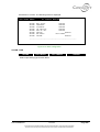
DISPLAY EXTENSION COUNTERS (MENU 4-2-1).......................................................... 95
DISPLAY TRUNK LINE COUNTERS (MENU 4-2-2)......................................................... 97
DISPLAY TRUNK GROUP COUNTERS (MENU 4-2-3).................................................... 98
DISPLAY OPERATOR CONSOLE COUNTERS (MENU 4-2-4) ....................................... 98
DISPLAY DEPARTMENT COUNTERS (MENU 4-2-5) ..................................................... 99
RESET COUNTERS (MENU 4-2-6) ................................................................................. 100
4.3
CHARGING OF INDIVIDUAL SUBSCRIBERS (MENU 4-3) ...................................102
4.4
LOGBOOK DISPLAY (MENU 4-4) ..........................................................................105
4.4.1
4.4.2
HARDWARE EVENTS RECORDED IN THE LOGBOOK............................................... 107
LOGICAL SECURITY BLOCKS ...................................................................................... 108
4.5
DELETE LOGBOOK (MENU 4-5) ...........................................................................109
4.6
DISPLAY STATUSES (MENU 4-6) .........................................................................110
4.6.1
4.6.2
4.6.3
4.6.4
4.6.5
4.6.6
4.6.7
4.6.8
4.6.9
4.7
TRAFFIC OBSERVATION (MENU 4-7)...................................................................135
4.7.1
4.7.2
4.7.3
4.7.4
4.7.5
4.7.6
4.7.7
Page 4
STATUS OF EXTENSIONS (MENU 4-6-1)...................................................................... 111
STATUS OF EXTERNAL TRUNKS (MENU 4-6-2) ......................................................... 116
STATUS OF DYNAMIC TRUNK GROUPS (MENU 4-6-3).............................................. 118
STATUS OF DATA LINKS (MENU 4-6-4) ....................................................................... 119
MAINTENANCE STATUS (MENU 4-6-5) ........................................................................ 120
ROAMING STATUS OF MOBILES (MENU 4-6-6) .......................................................... 122
FILLING STATUS OF TABLES (MENU 4-6-7)................................................................ 124
STATUS OF TCP TUNNEL CONNECTIONS (MENU 4-6-8) .......................................... 125
STATUS OF INTEGRATED VOICE BOXES (MENU 4-6-9)............................................ 125
DEFINE TRUNK GROUP OBSERVATION (MENU 4-7-1).............................................. 136
DISPLAY TRUNK GROUP OBSERVATION (MENU 4-7-2) ........................................... 137
BASE STATION OBSERVATION (MENU 4-7-3)............................................................ 139
BASE STATION TRUNK OBSERVATION (MENU 4-7-4) .............................................. 140
MOBILE OBSERVATION (MENU 4-7-5) ......................................................................... 141
RESET WIRELESS OBSERVATION (MENU 4-7-6)....................................................... 142
INTEGRATED VOICE BOX PARAMETERS (MENU 4-7-7)............................................ 143
15/09/2004
PS8149KENAA01
Ce document est la propriété de EADS et ne doit pas être reproduit ou communiqué sans autorisation.
This document is the property of EADS and may not be copied or circulated without authorisation.
.
4.7.8
5.
CAC SERVER MONITORING (MENU 4-7-8) .................................................................. 147
INSTALLER DATA (MENU 5) ........................................................................154
5.1
PROCESSOR ACCESS (MENU 5-1) ......................................................................155
5.1.1
5.1.2
5.1.3
5.2
FORMAT OF PAS FILES (MENU 5-1-1) ......................................................................... 155
DISPLAY OF PAS FILES (MENU 5-1-2) ......................................................................... 156
RESTART REQUEST (MENU 5-1-3) ............................................................................... 157
CONFIGURATION TRANSFER (MENU 5-2) ..........................................................160
5.2.1
5.2.2
SERIAL PORT CONFIGURATION TRANSFER ............................................................. 161
PARALLEL PORT CONFIGURATION TRANSFER ....................................................... 162
5.3
CONNECTION MANAGEMENT (MENU 5-3) NOT IN VALUES.............................163
5.4
IDENTIFICATION (MENU 5-4) ................................................................................165
5.4.1
5.4.2
5.4.3
5.4.4
5.5
TONE AND ANNOUNCEMENT DEFINITION (MENU 5-5) .....................................174
5.5.1
5.5.2
5.5.3
5.5.4
5.5.5
5.5.6
5.5.7
5.5.8
5.6
TONE AND ANNOUNCEMENT DEFINITION (MENU 5-5-1).......................................... 176
ANNOUNCEMENTS (MENU 5-5-2) ................................................................................. 184
DEFINITION OF SPOKEN LANGUAGES (MENU 5-5-3)................................................ 196
ALLOCATION OF TONES TO LANGUAGES (MENU 5-5-4) ......................................... 197
COMPANY/DEPARTMENT SPECIFIC TONES (MENU 5-5-4)....................................... 199
DEFINITION OF DIRECT ACCESS MESSAGES (MENU 5-5-6) .................................... 201
DISPLAY DEFINABLE TONES (MENU 5-5-7)................................................................ 202
EXTENNAL MUSIQUE LEVEL ADJUST. (MENU 5-5-8) (F1 AND F6) .......................... 204
SIGNALLING MANAGEMENT (MENU 5-6) ............................................................205
5.6.1
5.6.2
5.6.3
5.6.4
5.6.5
5.6.6
5.7
SOFTWARE IDENTIFICATION (MENU 5-4-1) ............................................................... 166
HARDWARE IDENTIFICATION (MENU 5-4-2) .............................................................. 169
DISPLAY DIGITAL SET NAMES (MENU 5-4-2 ON F1/F2 AND 5-4-3 ON F6) .............. 171
MANAGEMENT OF DIGITAL SET NAMES (MENU 5-4-3 ON F1/F2
AND 5-4-4 ON F6) ............................................................................................................ 173
SIGNALLING ACTIVATION (MENU 5.6.1)...................................................................... 205
NON ISDN SIGNALLING PARAMTERS (MENU 5-6-2).................................................. 209
ISDN SIGNALLING PARAMETERS (MENU 5.6.3)......................................................... 213
INITIALIZE A SIGNALLING TYPE (MENU 5-6-4) ........................................................... 216
RECORDING PARAMETERS (MENU 5-6-5) .................................................................. 217
IP SIGNALING PARAMETERS (MENU 5-6-6)................................................................ 219
ALARM CONFIGURATION (MENU 5-7) .................................................................221
5.7.1
5.7.2
INDIVIDUALIZED CONFIGURATION (MENU 5-7-1) ...................................................... 221
GLOBAL RESET (MENU 5-7-2) ...................................................................................... 224
PS8149KENAA01
15/09/2004
Ce document est la propriété de EADS et ne doit pas être reproduit ou communiqué sans autorisation.
This document is the property of EADS and may not be copied or circulated without authorisation.
Page 5
.
FIGURES
Figure 1: Menu 3 (System management - F1) ...................................................................................... 18
Figure 2: Menu 3 (System management - F6) ...................................................................................... 18
Figure 3: Time and date management .................................................................................................. 19
Figure 4: Date and time management (continued)................................................................................ 20
Figure 5: Card management (M6501L/R) ............................................................................................. 24
Figure 6: Card management (M6501L/R) (continued) .......................................................................... 24
Figure 7: Card management (M6504/M6540)....................................................................................... 26
Figure 8: "Equipment" card management (M6504/M6540)................................................................... 26
Figure 9: "Equipment" card management (M6504/M6540) (continued) ............................................... 27
Figure 10: "Equipment" card management (M6504/M6540) (continued) ............................................. 27
Figure 11: "Multibus" card management (M6504/6540) ....................................................................... 30
Figure 12: "Multibus" card management (M6504/6540) (continued) .................................................... 30
Figure 13: Link selection ....................................................................................................................... 33
Figure 14: Link selection (continued) .................................................................................................... 34
Figure 15: Link selection (continued) .................................................................................................... 34
Figure 16: Card management (XL, XS and XC)................................................................................... 35
Figure 17: Common boards management (XL)..................................................................................... 36
Figure 18: Common boards management (XL) (continued) ................................................................. 37
Figure 19: Common boards management (XL) (continued) ................................................................. 37
Figure 20: Common boards management (XL) (continued) ................................................................. 38
Figure 21: Common boards management (XL) (continued) ................................................................. 38
Figure 22: Common boards management (XL) (continued) ................................................................. 39
Figure 23: Card management (XS) ....................................................................................................... 40
Figure 24: XL hardware and software configurations – Migration (menu 3-2-2) .................................. 42
Figure 25: XS hardware and software configurations – Migration (menu 3-2-2) .................................. 44
Figure 26: XC hardware and software configurations – Migration (menu 3-2-2).................................. 47
Figure 27: IP board parameters management (menu 3-2-3) ................................................................ 49
Figure 28: IP card selection................................................................................................................... 50
Figure 29: ISDN board switches status (menu 3-2-4)........................................................................... 52
Figure 30: Configuration and recording (Menu 3-3) (F1) ...................................................................... 53
Figure 31: SVF-BVF configuration (Menu 3-3) (F6) ............................................................................. 53
Figure 32: Hardware configuration (M6501L/R IP PBX) ....................................................................... 54
Figure 33: Hardware configuration (M6504/M6540) ............................................................................. 56
Figure 34: Record announcements....................................................................................................... 57
Figure 35: SVF-BVF board access configuration (F6) (Menu 3-3-2) .................................................... 59
Figure 36 : Displaying IVS general characteristics (F6) (Menu 3-3-3)................................................. 60
Figure 37: Terminal management ......................................................................................................... 62
Figure 38: Menu 3-5 (Password management F1/F2/F6)..................................................................... 65
Figure 39: Compact format with password management ..................................................................... 68
Figure 40: Menu 3-6 (Parameter management).................................................................................... 69
Figure 41: Menu 3-8 (Software lock management)............................................................................... 72
Page 6
15/09/2004
PS8149KENAA01
Ce document est la propriété de EADS et ne doit pas être reproduit ou communiqué sans autorisation.
This document is the property of EADS and may not be copied or circulated without authorisation.
.
Figure 42: Selection of the SA function ................................................................................................. 73
Figure 43: Unlock hospital/hotel ............................................................................................................ 75
Figure 44: Display SA functions (F6)..................................................................................................... 76
Figure 45: Display SA functions (F6) (continued) ................................................................................. 77
Figure 46: Display SA functions (F6) (continued) ................................................................................. 77
Figure 47: Display SA functions (F6) (continued) ................................................................................. 78
Figure 48: Menu 3-9 (Integrated buffer management).......................................................................... 79
Figure 49: Integr. buffer parameter management (1)............................................................................ 79
Figure 50: Integr. buffer parameter management (2)............................................................................ 79
Figure 51: Reset flash ........................................................................................................................... 81
Figure 52: Administration password ...................................................................................................... 82
Figure 53: Menu 4 (Operation administration). ..................................................................................... 82
Figure 54: Menu 4-1 (Administration parameters). ............................................................................... 83
Figure 55: Administration parameters (continued) ................................................................................ 85
Figure 56: Administration parameters (continued) ................................................................................ 87
Figure 57: Administration parameters (continued) ................................................................................ 89
Figure 58: Administration parameters (continued) ................................................................................ 91
Figure 59: Administration parameters (continued - alarm validation on F6) ......................................... 92
Figure 60: Administration parameters (continued - alarm validation on F1) ......................................... 93
Figure 61: Administration parameters (continued - alarm validation on F2) ......................................... 93
Figure 62: Menu 4-2 (Overall charge data) ........................................................................................... 95
Figure 63: Display extension meters ..................................................................................................... 95
Figure 64: Extension counters............................................................................................................... 96
Figure 65: Display of trunk line counters (F2) ....................................................................................... 97
Figure 66: Display of trunk group counters (F2).................................................................................... 98
Figure 67: Display operator console counters....................................................................................... 98
Figure 68: Display department counters ............................................................................................... 99
Figure 69: Selection of counters to be reset ....................................................................................... 100
Figure 70: Reset counter password .................................................................................................... 100
Figure 71: Message indicating that the counters have been reset ..................................................... 101
Figure 72: Menu 4-3 (Directory number selection) ............................................................................. 102
Figure 73: Charging subscriber 28...................................................................................................... 102
Figure 74: Menu 4-4 (Logbook)........................................................................................................... 105
Figure 75: Password for deleting the logbook..................................................................................... 109
Figure 76: Delete logbook ................................................................................................................... 109
Figure 77: Menu 4-6 (Display statuses). ............................................................................................. 110
Figure 78: Status of extensions........................................................................................................... 111
Figure 79: Selection of a status to monitor.......................................................................................... 111
Figure 80: Display extensions (F1) (any status).................................................................................. 112
Figure 81: Display extensions (F6) (any status).................................................................................. 112
Figure 82: IP subscribers status - selection ........................................................................................ 113
Figure 83: IP subscribers status - display non-connected applicative sessions................................. 114
Figure 84: IP subscribers status - display connected applicative sessions ........................................ 114
Figure 85: Selection of a status to monitor.......................................................................................... 116
Figure 86: External trunk lines on the trunk group .............................................................................. 117
Figure 87: Selection of a status to monitor.......................................................................................... 118
Figure 88: Status of dynamic trunk groups ......................................................................................... 118
PS8149KENAA01
15/09/2004
Ce document est la propriété de EADS et ne doit pas être reproduit ou communiqué sans autorisation.
This document is the property of EADS and may not be copied or circulated without authorisation.
Page 7
.
Figure 89: Status of data links (F6) ..................................................................................................... 119
Figure 90: Status of data links (F6) (continued) .................................................................................. 119
Figure 91: Selection of a status to monitor.......................................................................................... 120
Figure 92: Display any maintenance status ........................................................................................ 121
Figure 93: Display any maintenance status (continued) ..................................................................... 121
Figure 94: Mobile localisation status ................................................................................................... 122
Figure 95: Mobile localisation (menu 4-6-6-1)..................................................................................... 122
Figure 96: Mobile localisation (cell basis) (menu 4-6-6-2) .................................................................. 123
Figure 97: Mobiles localised on cell xxxxxx ........................................................................................ 123
Figure 98: Filling status of tables......................................................................................................... 124
Figure 99: Filling status of tables (cont.) ............................................................................................. 124
Figure 100: Status of TCP tunnel connections.................................................................................... 125
Figure 101: Status of integrated voice boxes...................................................................................... 125
Figure 102: Overall view of voice mailboxes....................................................................................... 126
Figure 103: Displaying voice mailboxes from a directory number ...................................................... 126
Figure 104: Displaying voice mailboxes belonging to the same service class ................................... 127
Figure 105: Displaying voice mailboxes depending on operating mode............................................. 127
Figure 106: Displaying voice mailboxes by status .............................................................................. 128
Figure 107: Selecting a voice mailbox................................................................................................. 130
Figure 108: Displaying voice mailbox messages ................................................................................ 130
Figure 109: View messages involved in audit ..................................................................................... 132
Figure 110: Display general characteristics ........................................................................................ 133
Figure 111: Displaying voicemail busy statistics ................................................................................. 134
Figure 112: Displaying voicemail busy statistics (cont.)...................................................................... 134
Figure 113: Menu 4-7 (Traffic observation)......................................................................................... 135
Figure 114: Define trunk group observation........................................................................................ 136
Figure 115: Display trunk group observation ...................................................................................... 137
Figure 116: Observation of trunk group table...................................................................................... 138
Figure 117: Base station observation.................................................................................................. 139
Figure 118: Base station observation table......................................................................................... 139
Figure 119: Selection of trunk group to be observed .......................................................................... 140
Figure 120: Observation of the selected trunk group.......................................................................... 140
Figure 121: Mobile observation table .................................................................................................. 141
Figure 122: Rest wireless observation ................................................................................................ 142
Figure 123: Integrated voice box parameters ..................................................................................... 143
Figure 124: Audit start-up criteria ........................................................................................................ 144
Figure 125: Message deletion criteria ................................................................................................. 145
Figure 126: Reset voice mailbox flash ................................................................................................ 146
Figure 127: CAC server monitoring..................................................................................................... 147
Figure 128: Display flows towards other centres ................................................................................ 147
Figure 129: Display flows by CAC class ............................................................................................. 149
Figure 130: Reset the centre counters................................................................................................ 150
Figure 131: Reset class counters........................................................................................................ 152
Figure 132 : CAC servers status ......................................................................................................... 153
Figure 133: Password for access to installer data .............................................................................. 154
Figure 134: Menu 5 (Installer data). .................................................................................................... 154
Figure 135: Menu 5-1 (Processor access). ......................................................................................... 155
Page 8
15/09/2004
PS8149KENAA01
Ce document est la propriété de EADS et ne doit pas être reproduit ou communiqué sans autorisation.
This document is the property of EADS and may not be copied or circulated without authorisation.
.
Figure 136: Format of PAS files .......................................................................................................... 155
Figure 137: Display of PAS files.......................................................................................................... 156
Figure 138: Restart request................................................................................................................. 157
Figure 139: Menu 5-2 (Configuration transfer).................................................................................... 160
Figure 140: Serial port configuration transfer...................................................................................... 161
Figure 141: Parallel transfer of the configuration ................................................................................ 162
Figure 142: Menu 5-3 (Connection management) .............................................................................. 163
Figure 143: Identification (F1) ............................................................................................................. 165
Figure 144: Identification (F6) ............................................................................................................. 165
Figure 145: Software identification (F1) .............................................................................................. 166
Figure 146: Software identification (F2) .............................................................................................. 167
Figure 147: Software identification (XL) .............................................................................................. 168
Figure 148: Hardware identification (F6)............................................................................................. 169
Figure 149: Hardware identification (example of an XL cabinet) ........................................................ 169
Figure 150: Hardware identification (example of an XL cabinet) ........................................................ 170
Figure 151: Display digital set names ................................................................................................. 171
Figure 152: Display digital set names (continued) .............................................................................. 171
Figure 153: Display digital set names (continued) .............................................................................. 172
Figure 154: Display digital set names (end)........................................................................................ 172
Figure 155: Modification of digital set names...................................................................................... 173
Figure 156: Voice cards of the various PBX families (F1/F2) ............................................................. 174
Figure 157: Menu 5-5 (Tone and announcement definition - F1). ...................................................... 174
Figure 158: Menu 5-5 (Tone and announcement definition - F2). ...................................................... 175
Figure 159: Menu 5-5 (Tone and announcement definition - F6). ...................................................... 175
Figure 160: Selection of tone type....................................................................................................... 176
Figure 161: Normal dial tone ............................................................................................................... 180
Figure 162: Busy tone ......................................................................................................................... 183
Figure 163: Call accepted tone ........................................................................................................... 183
Figure 164: Menu 5-5-2 (Announcements on F1) ............................................................................... 184
Figure 165: Menu 5-5-2 (Announcements on F2) ............................................................................... 184
Figure 166: Summary of voice cards installed in F1/F2 PBXs............................................................ 185
Figure 167: Menu 5-5-2 (Announcements on XL/XS/XC)................................................................... 185
Figure 168: Summary of voice cards installed in F6 PBXs ................................................................. 185
Figure 169: Select music on hold ........................................................................................................ 186
Figure 170: Record RAM message ..................................................................................................... 186
Figure 171: Voice card recording duration .......................................................................................... 186
Figure 172: Listen to ROM messages................................................................................................. 187
Figure 173: Announcement message loading connection .................................................................. 188
Figure 174: View announcements (F1) ............................................................................................... 189
Figure 175: View announcements (F6) ............................................................................................... 189
Figure 176: Announcement distribution .............................................................................................. 191
Figure 177: Observe counters (F6) ..................................................................................................... 192
Figure 178: Reset counters (F6) ......................................................................................................... 193
Figure 179: Record announcements................................................................................................... 194
Figure 180: Definition of spoken languages........................................................................................ 196
Figure 181: Allocation of tones to languages ...................................................................................... 197
Figure 182: Allocation of tones to languages (continued)................................................................... 197
PS8149KENAA01
15/09/2004
Ce document est la propriété de EADS et ne doit pas être reproduit ou communiqué sans autorisation.
This document is the property of EADS and may not be copied or circulated without authorisation.
Page 9
.
Figure 183: Specific tone (single-company)........................................................................................ 199
Figure 184: Company/department specific tones................................................................................ 200
Figure 185: Company/department specific tones (cont.) .................................................................... 200
Figure 186: Definition of direct access messages .............................................................................. 201
Figure 187: Display of definable tones in single-company configuration............................................ 202
Figure 188: Display of definable tones in multi-company configuration.............................................. 203
Figure 189: Adjust external music level (F1)....................................................................................... 204
Figure 190: Adjust external music level (F6)....................................................................................... 204
Figure 191: Menu 5-6 (Signalling management)................................................................................. 205
Figure 192: Signalling activation ......................................................................................................... 205
Figure 193: Signalling for digital TRK.................................................................................................. 206
Figure 194: Signalling for analogue TRK ............................................................................................ 206
Figure 195: Signalling for tie-line......................................................................................................... 207
Figure 196: Signalling for ISDN:T0...................................................................................................... 207
Figure 197: Signalling for ISDN:T2...................................................................................................... 208
Figure 198: Signalling for voice IP....................................................................................................... 208
Figure 199: Non ISDN signalling parameters...................................................................................... 209
Figure 200: Non ISDN signalling parameters (continued) .................................................................. 210
Figure 201: Non ISDN signalling parameters (continued) .................................................................. 211
Figure 202: Non ISDN signalling parameters (end) ............................................................................ 211
Figure 203: ISDN signalling parameters ............................................................................................. 213
Figure 204: ISDN signalling parameters (continued) .......................................................................... 213
Figure 205: ISDN signalling parameters (continued) .......................................................................... 214
Figure 206: ISDN signalling parameters (continued) .......................................................................... 214
Figure 207: Initialise a signalling type ................................................................................................. 216
Figure 208: R2 Standard recorder parameters ................................................................................... 217
Figure 209: IP signalling parameters .................................................................................................. 219
Figure 210: Alarm configuration .......................................................................................................... 221
Figure 211: Configure the alarms: selection ....................................................................................... 221
Figure 212: Alarm configuration .......................................................................................................... 223
Figure 213: Configure the alarms: global reset ................................................................................... 224
Page 10
15/09/2004
PS8149KENAA01
Ce document est la propriété de EADS et ne doit pas être reproduit ou communiqué sans autorisation.
This document is the property of EADS and may not be copied or circulated without authorisation.
.
1.
1.1
ABOUT THIS DOCUMENT
PURPOSE OF THIS DOCUMENT
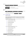
This document describes the MMCs of the PBX from software release 3.2, with the
exception of the MMCs relating to data transmission which are dealt with in a separate
manual.
1.2
TARGET AUDIENCE OF THIS DOCUMENT
This document is intended for installation technicians who configure the PBX and
implement the telephone features introduced by this software release.
1.3
SCOPE OF THIS DOCUMENT
This document applies to M6501 IP PBX, M6501L IP PBX, M6501R IP PBX, M6504 IP
PBX, M6540 IP PBX, NeXspan C-S-L running software release 3.2 or later.
1.4
CONTENTS OF THIS DOCUMENT
This document describes all the means available to the operator for management of the
M6501 IP PBX, M6501L IP PBX, M6501R IP PBX, M6504 IP PBX, M6540 IP PBX and
NeXspan C-S-L from an operating terminal.
The set of Man Machine Commands (MMCs) described in this manual enable you to
operate and manage M6501 IP PBX, M6501L IP PBX, M6501R IP PBX, M6504 IP PBX,
M6540 IP PBX and NeXspan C-S-L.
This manual is composed of chapters ordered according to the tree structure of the MMCs
as presented on the screen of the operating console.
1.5
TERMINOLOGY
1.5.1
TERMS AND EXPRESSIONS
Not applicable.
1.5.2
ABBREVIATIONS
F1
PBX range comprising M6501 L/R IP PBX
F2
PBX range comprising M6504 IP PBX, M6504 L IP PBX, M6540 IP PBX
F5
Software application (Call Manager)
F6
PBX range comprising NeXspan C (XC), NeXspan S (XS) and NeXspan L (XL)
PS8149KENAA01
15/09/2004
Ce document est la propriété de EADS et ne doit pas être reproduit ou communiqué sans autorisation.
This document is the property of EADS and may not be copied or circulated without authorisation.
Page 11
.
1.6
REFERENCE DOCUMENTS
The information contained in this manual refers to the following documents:
1.7
♦
M6501L/R IP PBX
Installation manual
♦
M6504
Installation manual
♦
M6504L IP PBX
Installation manual
♦
M6540 IP PBX
Installation manual
♦
NeXspan range (XL/XS/XC)
Installation and Maintenance Manual
♦
Telephone sets manual
REMINDER CONCERNING THE LAW ON INFORMATION
TECHNOLOGY
The user is reminded that commissioning PBXs in the workplace must comply with
the recommendations of the IT law in force.
The user's attention is also drawn to any clauses applicable in laws relating to the
confidentiality of calls transmitted by means of telecommunications.
Page 12
15/09/2004
PS8149KENAA01
Ce document est la propriété de EADS et ne doit pas être reproduit ou communiqué sans autorisation.
This document is the property of EADS and may not be copied or circulated without authorisation.
.
2.
2.1
MENUS
SYSTEM MANAGEMENT MENU
PBX MANAGEMENT
1 - TELEPHONY MANAGEMENT
2 - DATA MANAGEMENT
3 - SYSTEM MANAGEMENT
4 - OPERATION ADMINISTRATION
5 - INSTALLER DATA
Password "INSTA"
SYSTEM MANAGEMENT
1 – DATE AND TIME MANAGEMENT
2 – CARD MANAGEMENT
3 - CONFIGURATION AND RECORDING (F1)
3 – HARDWARE CONFIGURATION MANAGEMENT
(F2)
3 - FVS-BVS CONFIGURATION (F6)
4 – TERMINAL MANAGEMENT
5 – PASSWORD MANAGEMENT
6 – PARAMETER MANAGEMENT
7 – MULTI-SITE MANAGEMENT
8 – SOFTWARE LOCK MANAGEMENT
9 – INTEGRAT. BUFFER MANAGEMENT
MANAGEMENT OF DATE AND TIME
Menu 3-1
CARD MANAGEMENT (F1)
Menu 3-2
CARD MANAGEMENT (F2)
1 - EQUIPMENT CARD SLOTS
2 - MULTIBUS SLOTS
Menu 3-2
CARD MANAGEMENT (F6)
1 – COMMON BOARDS MANAGEMENT
2 - MOTHER BOARD MANAGEMENT - MIGRATION
3 - IP BOARD PARAMETERS MANAGEMENT
4 - ISDN BOARD SWITCHES STATUS
Menu 3-2
CONFIGURATION AND RECORDING (F1)
1 - HARDWARE CONFIGURATION
2 - BVF: RECORDING MESSAGES
Menu 3-3
HARDWARE CONFIGURATION MANAGEMENT (F2)
Menu 3-3
FVS-BVS CONFIGURATION (F6)
1 - SVF-BVF: RECORDING MESSAGES
2 - SVF-BVF BOARD ACCESS CONFIGURATION
Menu 3-3
TERMINAL MANAGEMENT
PS8149KENAA01
Menu 3-4
15/09/2004
Ce document est la propriété de EADS et ne doit pas être reproduit ou communiqué sans autorisation.
This document is the property of EADS and may not be copied or circulated without authorisation.
Page 13
.
MANAGEMENT PASSWORD
PARAMETER MANAGEMENT
MULTI-SITE MANAGEMENT
1 - DEFINITION OF CENTERS AND SITES
2 – MESSAGE ROUTING
3 – CIRCUIT MANAGEMENT
4 – PERMANENT LINK MANAGEMENT
5 - RESOURCES ON OTHER SITES
6 - SITE CONFIGURATION TOOL
7 – VOICE OVER IP PARAMETERS
Page 14
Menu 3-5
Menu 3-6
Menu 3-7
SOFTWARE LOCK MANAGEMENT
1 – UNLOCK SA FUNCTIONS
2 – DISPLAY SA FUNCTIONS
Menu 3-8
INTEGR. BUFFER MANAGEMENT
1 – PARAMETER MANAGEMENT
2 – RESET FLASH
Menu 3-9
15/09/2004
PS8149KENAA01
Ce document est la propriété de EADS et ne doit pas être reproduit ou communiqué sans autorisation.
This document is the property of EADS and may not be copied or circulated without authorisation.
.
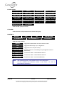
2.2
OPERATION ADMINISTRATION MENU
PBX MANAGEMENT
1 - TELEPHONY MANAGEMENT
2 - DATA MANAGEMENT
3 - SYSTEM MANAGEMENT
4 - OPERATION ADMINISTRATION
5 - INSTALLER DATA
Password "INSTA"
OPERATION ADMINISTRATION
1 – ADMINISTRATION PARAMETERS
2 - OVERALL DISPLAY OF CHARGE COUNTERS
3 – CHARGING OF INDIVIDUAL SUBSCRIBERS
4 - LOGBOOK DISPLAY
5 - DELETE LOGBOOK
6 – DISPLAY STATUSES
7 – TRAFFIC OBSERVATION
ADMINISTRATION PARAMETERS
OVERALL DISPLAY OF CHARGE COUNTERS
1 – DISPLAY EXTENSION COUNTERS
2 – DISPLAY TRUNK LINE COUNTERS
3 – DISPLAY TRUNK GROUP COUNTERS
4 – DISPLAY OPERATOR CONSOLE COUNTERS
5 – DISPLAY DEPARTMENT COUNTERS
6 – RESET COUNTERS
Menu 4-2
CHARGING OF INDIVIDUAL SUBSCRIBERS
Menu 4-3
LOGBOOK
Menu 4-4
DELETE LOGBOOK
DISPLAY STATUSES
1 – STATUS OF EXTENSIONS
2 – STATUS OF EXTERNAL TRUNKS
3 – STATUS OF DYNAMIC TRUNK GROUPS
4 – STATUS OF DATA LINKS
5 – MAINTENANCE STATUS
6 – ROAMING STATUS OF MOBILES
7 – FILLING STATUS OF TABLES
8 – STATUS OF TUNNEL TCP CONNECTIONS
9 – STATUS OF INTEGRATED VOICE BOXES
TRAFFIC OBSERVATION
1 – DEFINE TRUNK GROUP OBSERVATION
2 – DISPLAY TRUNK GROUP OBSERVATION
3 – BASE STATION OBSERVATION
4 – BASE STATION TRUNK OBSERVATION
5 – MOBILE OBSERVATION
6 - RESET WIRELESS OBSERVATION
7 – INTEGRATED VOICE BOX PARAMETERS
8 - CAC SERVER MONITORING
PS8149KENAA01
Menu 4-1
Menu 4-5
Menu 4-6
Menu 4-7
15/09/2004
Ce document est la propriété de EADS et ne doit pas être reproduit ou communiqué sans autorisation.
This document is the property of EADS and may not be copied or circulated without authorisation.
Page 15
.
2.3
INSTALLER DATA MENU
PBX MANAGEMENT
1 - TELEPHONY MANAGEMENT
2 - DATA MANAGEMENT
3 - SYSTEM MANAGEMENT
4 - OPERATION ADMINISTRATION
5 - INSTALLER DATA
Password "INSTA"
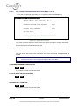
INSTALLER DATA
1 – PROCESSOR ACCESS
2 – CONFIGURATION TRANSFER
3 – CONNECTION MANAGEMENT
4 – IDENTIFICATION
5 – TONE AND ANNOUNCEMENT DEFINITION
6 – SIGNALLING MANAGEMENT
7 – ALARM CONFIGURATION
PROCESSOR ACCESS
1 – FORMAT OF PAS FILES
2 – DISPLAY OF PAS FILES
3 – RESTART REQUEST
CONFIGURATION TRANSFER
Menu 5-2
CONNECTION MANAGEMENT
Menu 5-3
IDENTIFICATION (F1)
1 – SOFTWARE IDENTIFICATION
2 – DISPLAY DIGITAL SET NAMES
3 – MANAGEMENT OF DIGITAL SET NAMES
Menu 5-4
IDENTIFICATION (F6)
1 – SOFTWARE IDENTIFICATION
2 - HARDWARE IDENTIFICATION
3 – DISPLAY DIGITAL SET NAMES
4 – MANAGEMENT OF DIGITAL SET NAMES
Menu 5-4
TONE AND ANNOUNCEMENT DEFINITION
1 – TONE DEFINITION
2 – ANNOUNCEMENTS
3 – DEFINITION OF SPOKEN LANGUAGES
4 – ALLOCATION OF TONES TO LANGUAGES
5 – COMPANY/DEPARTMENT SPECIFIC TONES
6 – DEFINITION OF DIRECT ACCESS MESSAGES
7 – DISPLAY DEFINABLE TONES
8 – EXTENNAL MUSIQUE LEVEL ADJUST.
Page 16
Menu 5-1
15/09/2004
Menu 5-5
PS8149KENAA01
Ce document est la propriété de EADS et ne doit pas être reproduit ou communiqué sans autorisation.
This document is the property of EADS and may not be copied or circulated without authorisation.
.
SIGNALlING MANAGEMENT
1 - SIGNALLING ACTIVATION
2 - NON ISDN SIGNALLING PARAMETERS
3 - ISDN SIGNALLING PARAMETERS
4 - INITIALIZE A SIGNALLING TYPE
5 - RECORDING PARAMETERS
6 - IP SIGNALLING PARAMETERS
ALARM CONFIGURATION
1 - INDIVIDUALIZED CONFIGURATION
2 - GLOBAL RESET
2.4
Menu 5-6
Menu 5-7
DATA MANAGEMENT (MENU 2)
Since the data management functions are of great importance, they are not described in
this manual, and are dealt with in a separate manual (reference PS8720ENJAA01).
PS8149KENAA01
15/09/2004
Ce document est la propriété de EADS et ne doit pas être reproduit ou communiqué sans autorisation.
This document is the property of EADS and may not be copied or circulated without authorisation.
Page 17
.
3.
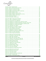
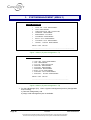
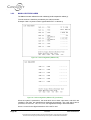
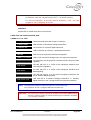
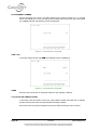
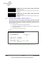
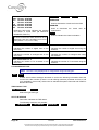
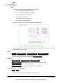
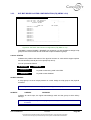
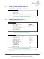
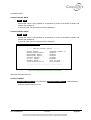
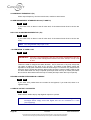
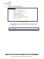
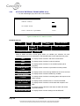
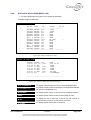
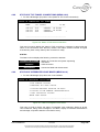
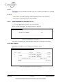
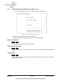
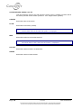
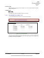
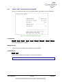
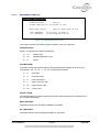
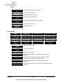
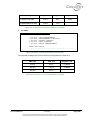
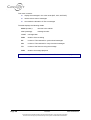
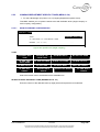
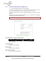
SYSTEM MANAGEMENT (MENU 3)
SYSTEM MANAGEMENT
1
2
3
4
5
6
7
8
9
DATE AND TIME MANAGEMENT
CARD MANAGEMENT
CONFIGURATION AND RECORDING
TERMINAL MANAGEMENT
MANAGEMENT PASSWORD
PARAMETER MANAGEMENT
MULTI-SITE MANAGEMENT
SOFTWARE LOCK MANAGEMENT
INTEGR. BUFFER MANAGEMENT
ENTER YOUR CHOICE
.
---------------------------------------------Figure 1: Menu 3 (System management - F1)
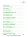
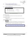
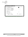
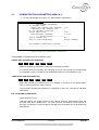
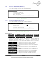
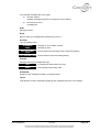
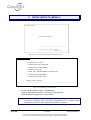
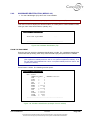
SYSTEM MANAGEMENT
1 DATE AND TIME MANAGEMENT
2 CARD MANAGEMENT
3.SVF-BVF CONFIGURATION
4 TERMINAL MANAGEMENT
5 PASSWORD MANAGEMENT
6 PARAMETER MANAGEMENT
7 MULTI-SITE MANAGEMENT
8 SOFTWARE LOCK MANAGEMENT
9 INTEGRAT. BUFFER MANAGEMENT
ENTER YOUR CHOICE
.
----------------------------------------
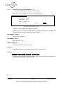
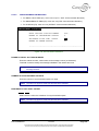
Figure 2: Menu 3 (System management - F6)
For the Call Manager (F5): Menu 3 (System management) levels 3 (Configuration
and recording),
4 (Terminal management), and
9 (Integr. buffer management) are not available.
Page 18
15/09/2004
PS8149KENAA01
Ce document est la propriété de EADS et ne doit pas être reproduit ou communiqué sans autorisation.
This document is the property of EADS and may not be copied or circulated without authorisation.
.
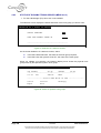
3.1
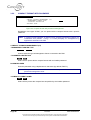
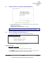
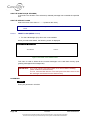
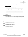
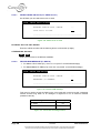
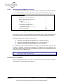
DATE AND TIME MANAGEMENT (MENU 3-1)
For the Call Manager (F5): Menu 3-1 (Date and time management).
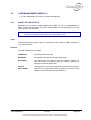
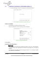
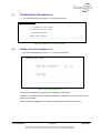
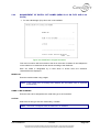
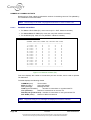
3.1.1
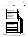
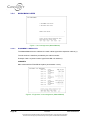
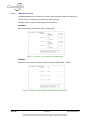
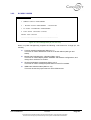
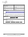
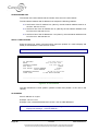
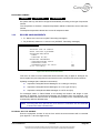
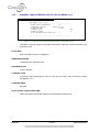
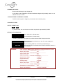
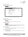
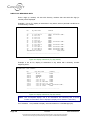
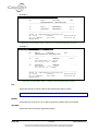
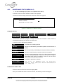
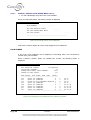
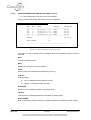
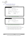
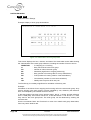
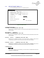
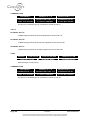
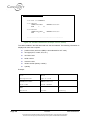
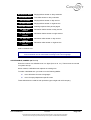
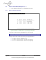
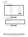
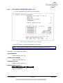
DATE AND TIME DEFINITION
MANAGEMENT OF DATE AND TIME
PRESENT TIME AND DATE
- TIME (format hh mm ss)
- DATE (format dd mm yyyy)
15 51 46
30 06 2003
NEXT PROGRAMMED TIME CHANGE
NO
------------------------------------------------------
Figure 3: Time and date management
TIME (FORMAT HH MM SS)
Enter the hour (hh), minutes (mm) and seconds (ss) using 2 digits for each value.
DATE (FORMAT DD MM YYYY)
Enter the day (dd) and month (mm), using 2 digits for each value, and the year (yyyy),
using 4 digits.
NEXT PROGRAMMED TIME CHANGE
NO
YES
This menu is used to switch to day light-saving time or to local standard time on the
requested date: this avoids having to carry out these changes on the customer site on the
day in question.
When you select this option, 3 other fields are displayed (see the section below).
Note: In this release, the customer can make the change himself using the interactive
menu on an attendant console or a digital set declared as a maintenance set.
PS8149KENAA01
15/09/2004
Ce document est la propriété de EADS et ne doit pas être reproduit ou communiqué sans autorisation.
This document is the property of EADS and may not be copied or circulated without authorisation.
Page 19
.
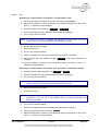
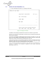
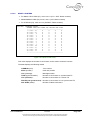
3.1.2
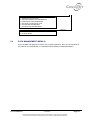
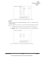
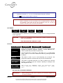
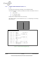
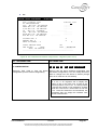
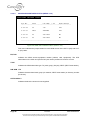
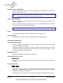
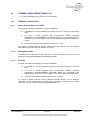
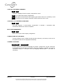
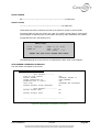
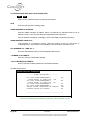
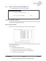
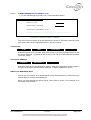
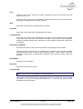
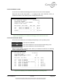
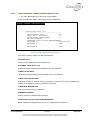
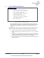
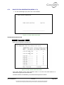
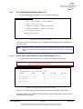
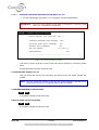
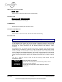
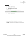
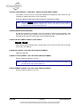
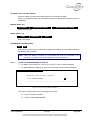
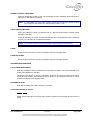
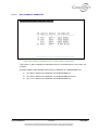
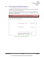
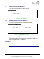
PROGRAMMING A CHANGE OF TIME
MANAGEMENT OF DATE AND TIME
PRESENT TIME AND DATE
- TIME (format hh mm ss)
- DATE (format dd mm yyyy)
15 53 14
30 06 2003
NEXT
- on
- At
- IT
YES
.....
.....
.....
PROGRAMMED TIME CHANGE
(date format dd mm)
(time format hh mm)
WILL BE (time format hh mm)
------------------------------------------------------
Figure 4: Date and time management (continued)
ON (DATE FORMAT DD MM)
Enter the date of the change: the day (dd) and month (mm), using 2 digits for each value.
AT (TIME FORMAT HH MM)
Enter the time of the change: the hour (hh) and minutes (mm), using 2 digits for each
value.
IT WILL BE (TIME FORMAT HH MM)
Enter the desired time for the change: the hour (hh) and minutes (mm), using 2 digits for
each value.
Note: The date and time can be updated on an attendant console or on a 520 or 640
digital set declared as a maintenance set in its extension characteristics. In
menu 1-7-2 (Miscellaneous Parameters), select YES for date and time
management.
Programming on telephone sets is as follows:
FUNCT. → SERVER → MORE → SYSTEM MANAGEMENT → ACCESS →
DATE and TIME.
The date and time are updated on the sets after any operation (Example: offhook/on-hook), after passing 8 p.m. or midnight, by unplugging or plugging in the
sets following an automatic reset.
Page 20
15/09/2004
PS8149KENAA01
Ce document est la propriété de EADS et ne doit pas être reproduit ou communiqué sans autorisation.
This document is the property of EADS and may not be copied or circulated without authorisation.
.
3.2
CARD MANAGEMENT (MENU 3-2)
For the Call Manager (F5): Menu 3-2 (Card management).
3.2.1
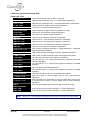
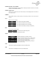
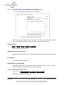
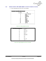
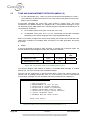
CARD TYPE AND STATUS
Depending on the system installed (M6501L/R IP PBX, XL, XS, XC M6504/M6540 IP
PBX), a screen which displays the various cards installed on the PBX appears: the card
type and status are displayed.
Note: Menu 3-2 (Card management) proposes 4 sub-menus for the X range. To declare
a card in an XL/XS/XC, select menu 3-2-1 (see section 3-2-5) .
TYPE
This field indicates the type of card in the specified location when the PBX is powered on
or on TOTAL RESET.
STATUS
This field indicates the card status:
IN SERVICE:
Card being used in the PBX.
DISABLED:
Card disabled because of a change being made.
NOT EQUIP.:
Card absent from the system or used by an MMC to replace one
card with another of a different type (for example, replacing an
analogue card with a digital card).
FAULTY:
Card previously in service and has been removed from the system.
NET ALARM:
LSB status for NETWORK cards (in particular PTx/PVI) which
indicates network disconnection (IP, ISDN, etc.).
PS8149KENAA01
15/09/2004
Ce document est la propriété de EADS et ne doit pas être reproduit ou communiqué sans autorisation.
This document is the property of EADS and may not be copied or circulated without authorisation.
Page 21
.
3.2.2
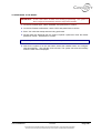
PROCEDURE FOR INSTALLING A CARD
Warning:
♦
Before disabling a card, all the equipment interfaces on that card must first be
disabled.
♦
A card which supports an attendant console, a night console trunk group
declared in a trunk group cannot be changed to the status NOT EQUIP. This
equipment must be deleted beforehand.
♦
If no network link is connected to the PTx card, no TCP gateway link can be
enabled.
IMPORTANT: Always switch off your device before installing or uninstalling a card,
unless it is an LA16X or LN16X card in an XL cabinet (F6).
3.2.2.1
F1/F2
1. Set all the equipment interfaces on the card out of service (DISABLED).
2. Delete all the directory numbers assigned to the equipment interfaces on the card in
menu 1-1-1 (Extension characteristics).
3. Change the status of the carte from In service to Not equip.
4. Power off the PBX (Switch on the face plate of the power supply module) in the main
cabinet or the expansion cabinet.
5. Remove the card from the PBX.
6. Insert the new card.
7. Power on the PBX (Switch on the face plate of the power supply module) in the main
cabinet or the expansion cabinet.
8. Select the card type and validate the status In service (wait until the download is
complete).
9. If you are installing a subscriber card, redefine the directory numbers in menu 1-1-1
(Extensions characteristics).
Note: Changing the status of the card from In service to Not equip. destroys all the
links previously created. For a PT2 card to keep the links created when changing
from x channels to y channels, change the status of the card from In service to
Disabled (instead of Not equip.).
Page 22
15/09/2004
PS8149KENAA01
Ce document est la propriété de EADS et ne doit pas être reproduit ou communiqué sans autorisation.
This document is the property of EADS and may not be copied or circulated without authorisation.
.
3.2.2.2
F6
Replacing an "old generation" card with an "old generation" card:
1. Set all the equipment interfaces on the card out of service (DISABLED).
2. Delete all the directory numbers assigned to the equipment interfaces on the card in
menu 1-1-1 (Extension characteristics).
3. Change the status of the carte from In service to Not equip.
4. Power off the PBX (the main cabinet and the expansion cabinet(s)).
5. If it is an XS, open the cabinet.
Note: For further information on installing and replacing a card in an XL, XS or XC
cabinet, refer to “X-range Installation and Maintenance Guide”.
6. Remove the card from the PBX.
7. Insert the new card.
8. If it is an XS, close the cabinet.
9. Power on the PBX again (the main cabinet and the expansion cabinet(s).
10. Select the card type and validate the status In service (wait until the download is
complete).
11. If you are installing a subscriber card, redefine the directory numbers in menu 1-1-1
(Extensions characteristics).
Replacing an "old generation" card with a "new generation" card (LA16X, LN16X):
1. Change the (LA8, LN8) card status from In service to Disabled.
2. Power off the PBX (the main cabinet and the expansion cabinet(s)).
3. If it is an XS, open the cabinet.
Note: For further information on installing and replacing a card in an XL, XS or XC
cabinet, refer to “X-range Installation and Maintenance Guide”.
4. Remove the card from the PBX.
5. Insert the new card.
Note: In an XL cabinet, you can hot plug or unplug an LA16X or LN16X card. For further
information on an XL, XS or XC cabinet, refer to “X-range Installation and
Maintenance Guide”.
6. If it is an XS, close the cabinet.
7. Power on the PBX again (the main cabinet and the expansion cabinet).
8. Select card type and confirm the status In service.
9. Define all the directory numbers for the additional equipment interfaces on the card in
menu 1-1-1 (Extension characteristics).
PS8149KENAA01
15/09/2004
Ce document est la propriété de EADS et ne doit pas être reproduit ou communiqué sans autorisation.
This document is the property of EADS and may not be copied or circulated without authorisation.
Page 23
.
3.2.3
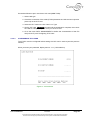
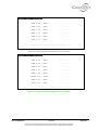
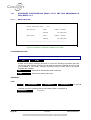
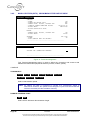
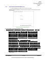
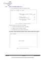
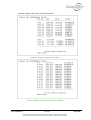
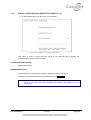
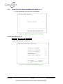
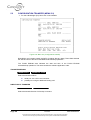
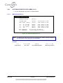
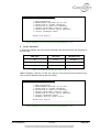
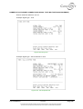
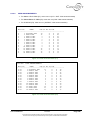
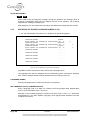
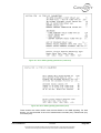
M6501L/R IP PBX CARDS
The M6501L has two cabinets: the main cabinet (0) and the expansion cabinet (1).
The slot number is therefore preceded by the cabinet number.
Example: Card 0-2 (second card of type 8 MIXD EXT. in cabinet 0)
Figure 5: Card management (M6501L/R)
Figure 6: Card management (M6501L/R) (continued)
When the system is powered on, the cards which do not have a processor, and which are
installed in the PBX, are identified and displayed automatically. The cards which have a
processor, such as CA1, LS1, CP1, CS1, are signalled as being in download status.
Slot 0-7 is used for the digital extensions of the OCT4 card.
Page 24
15/09/2004
PS8149KENAA01
Ce document est la propriété de EADS et ne doit pas être reproduit ou communiqué sans autorisation.
This document is the property of EADS and may not be copied or circulated without authorisation.
.
Slots 2-0 to 3-7 are used on the M6501L IP PBX (double cabinet).
If the equipment interface has LD4 or LT2 cards, these must be put in service using this
menu. The LT2 card is fitted for T2 or S2 (PRI).
The LS2 or LT2 card can only be installed in slot 04 or 05 (and 00 and 01 for 4 T2). You
can therefore use the LS2 card in two ways:
♦
ISDN:T2 Signalling - (telephone mode)
♦
QSIG signalling - (multi-site links)
Example:
You can use an LS2 card for ISDN:T2 in slot 5 and another LS2 card for QSIG
signalling in slot 04.
CAUTION:
An LT2 or LS2 card placed in eq1 requires a TMOCT4 card.
CARD (CABINET NUMBER – SLOT NUMBER): TYPE
••••••••
4 AB. ANAL.
Use the terminal space bar to select a card type.
LA4 card for 4 analogue extensions.
4 AB. BOTHWAY
LM4 card for 4 mixed extensions.
4 AB. COMMON
LN4 card for 4 digital extensions.
8 AB. ANAL.
8 AB. BOTHWAY
8 AB. COMMON
2 ANAL TK
4 ANAL TK
ISDN 2S0
ISDN T0-S0
ISDN 2T0
LD4
TIE LINE
CA1
CS1
CP1
LB4
LS2
LT2
LA8 card for 8 analogue extensions.
LM8 card for 8 mixed extensions.
LN8 card for 8 digital extensions.
LR1 card with 2 analogue trunk line equipment interfaces.
LR4 card with 4 analogue trunk line equipment interfaces.
LS1 card, 2 S0 equipment interfaces configuration.
LS1 card, 1 T0 + 1 S0 equipment interface configuration.
LS1 card, 2 T0 equipment interfaces configuration.
T0/S0 card for 2- or 4-channel radio base stations.
IA1/LI1 card for 2- or 4-wire tie-line equipment interfaces.
Card for 4 V24 asynchronous links.
Card for 2 X25 asynchronous links.
Packet circuit coupler card with two equipment interfaces.
Card with 4 CT2 radio base station equipment interfaces.
LS2 card with ISDN T2 (PRI) and QSIG signalling.
Card fitted for S2, T2 (PRI), PCM or reduced.
CC1
BVF
PTx
Card with synchronous announcements.
Card with IVB and synchronous announcements.
PTx card which manages links (maximum 16) and carries out
gateway functions (TCP/IP-X25) and tunnelling (X25 over IP).
CAUTION: No PTx card can be enabled unless the network cable is
connected.
PS8149KENAA01
15/09/2004
Ce document est la propriété de EADS et ne doit pas être reproduit ou communiqué sans autorisation.
This document is the property of EADS and may not be copied or circulated without authorisation.
Page 25
.
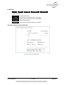
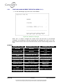
3.2.4
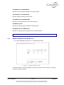
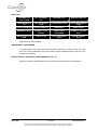
M6504/M6540 CARDS
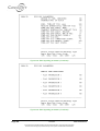
Figure 7: Card management (M6504/M6540)
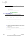
3.2.4.1
EQUIPMENT CARD SLOTS
The M6504/M6540 has two cabinets: the main cabinet (0) and the expansion cabinet (1).
The slot number is therefore preceded by the cabinet number.
Example: Card 0-2 (second card of type PCM LRN-2 in cabinet 0).
CABINET 0
Main cabinet with an FP04PD back plane (TELEPHONE + DATA).
Figure 8: "Equipment" card management (M6504/M6540)
Page 26
15/09/2004
PS8149KENAA01
Ce document est la propriété de EADS et ne doit pas être reproduit ou communiqué sans autorisation.
This document is the property of EADS and may not be copied or circulated without authorisation.
.
Figure 9: "Equipment" card management (M6504/M6540) (continued)
CABINET 1
Expansion cabinet with an FP04MD (TELEPHONE + DATA) or a FP04ER back plan
(TELEPHONE only).
For card management in the system, the main cabinet back plane (FP04MD) is divided in
two:
♦
EQUIPMENT side for the EQT card type. (example: LRN or LAE type cards),
♦
MULTIBUS side for CLX card type (example: ADP (T2) or ADB (T0/S0) type
cards.
Figure 10: "Equipment" card management (M6504/M6540) (continued)
PS8149KENAA01
15/09/2004
Ce document est la propriété de EADS et ne doit pas être reproduit ou communiqué sans autorisation.
This document is the property of EADS and may not be copied or circulated without authorisation.
Page 27
.
CARD TYPE ON TELEPHONE BUS SIDE
CARD X-XX: TYPE
••••••••
Use the terminal space bar to select a card type.
LRN – 1 PCM
LRN card with 2 PCM (64 TSs), in 1 PCM (PCM0) configuration.
LRN – 2 PCM
LRN card with 2 PCM (64 TSs), in 2 PCM (PCM0-PCM1) configuration.
16 AB. ANAL.
LAB card FOR 16 Z interface analogueue extensions.
16 AB. COMMON
LAI card for 16 I interface digital extensions.
16 AB. NUM + DATA
LAN.D card with 16 digital extensions (telephone + data).
32 AB. ANAL.
LAE card for 32 Z interface analogue extensions.
32 AB. COMMON
LAJ card for 32 I interface digital extensions.
ISDN 8T0
LAS card, 8 T0 equipment interfaces configuration.
ISDN 6T0 - 2S0
LAS card, 6 T0 + 2 S0 equipment interfaces configuration.
ISDN 4T0 - 4S0
LAS card, 4 T0 +4 S0 equipment interfaces configuration.
ISDN 2T0 - 6S0
LAS card, 2 T0 +6 S0 equipment interfaces configuration.
ISDN 8S0
LAS card, 8 S0 equipment interfaces configuration.
8 AN / 4 DIG / 4 TK
LAR card with 8 analogue extensions + 4 digital extensions + 4 analogue
trunk line equipment interfaces.
8 ANAL. TK.LRA/LRD
LRD or LRA card with 8 analogue trunk line equipment interfaces.
8 ANAL.TK.LRB
LRB or LRA card with 8 analogue trunk line equipment interfaces.
4 TIE LINE-A
LIA card with four 2-wire tie-line equipment interfaces.
4 TIE LINE-B
LIB card with four 2- or 4-wire tie-line equipment interfaces, and voice
frequency signalling.
4 TIE LINE-C
LIC card with four 2- or 4-wire tie-line equipment interfaces, and E&M
signalling.
4 TIE LINE-D
LID card, specific AVS 2000 application.
8 TIE LINE-E
LIE card with eight 2- or 4-wire tie-line equipment interfaces, and E&M
signalling.
16 RADIO BASES
LAC card, used to connect 16 CT2 wireless base stations.
CONFER 1 PCM
CCB card Used to connect digital sets for the multi-conference
application.
CONFER 2 PCM
CCB card where one PCM used to connect a digital tape recorder and
a second PCM is used to connect digital sets for multi-conference
application.
CCA 16
ANNOUNCEMENT
CCA card with spoken announcements and conference circuits.
CCS 1 PCM
CCS card with synchronised messages, in 1 PCM configuration.
CCS 2 PCM
CCS card with synchronised messages, in 2 PCM configuration.
Note: The LRN 1 or 2 PCM field only appears for card slots 01 and 02 in the main cabinet.
Page 28
15/09/2004
PS8149KENAA01
Ce document est la propriété de EADS et ne doit pas être reproduit ou communiqué sans autorisation.
This document is the property of EADS and may not be copied or circulated without authorisation.
.
Reminder: The LAS card is used to connect 8 BRIs (type T0 or S0) to ISDN terminals
(8 interfaces, each with 2 B channels (64 kb/s) + 1 D channel (16 kb/s).
For LAS card operation, an IFS link must be declared (+ LAS - CLF wire
plugged in): see "Configuring "IFS" links".
CABINET 2
Cabinet with an FP04E back plane (TELEPHONE).
CARD TYPE ON TELEPHONE BUS SIDE
CARDS 01 TO 16: TYPE
• • • • • • • • •
Use the terminal space bar to select a card type.
16 ANALOG EXT.
LAB card with 16 Z interface analogue extensions.
16 DIGITAL EXT.
LAI card with 16 I interface digital extensions.
DIGITAL EXT.+TDD
LAN.D card with 16 I interface + data digital extensions.
ISDN 8S0
LAS card, 8 S0 equipment interfaces configuration.
8 ANAL. TK.LRA/LRD
LRD or LRA card with 8 analogue trunk line equipment interfaces.
4 TIE LINE–A
LIA card with 4 tie-line equipment interfaces and 50 Hz type or E&M
signalling.
4 TIE LINE-B
LIB card with four 2- or 4-wire tie-line equipment interfaces and
voice frequency signalling.
4 TIE LINE-C
LIC card with four 2- or 4-wire tie-line equipment interfaces and
E&M signalling.
8 TIE LINE-E
LIE card with eight 2- or 4-wire tie-line equipment interfaces and
50 Hz, E&M or 2E&2M signalling.
8 AN / 4 DIG / 4 TK
LAR card with 8 Z interface analogue extensions, 4 I interface
digital extensions, and 4 analogue trunk line equipment interfaces.
Note: The telephone expansion cabinet 2 supports LAS 8S cards only.
EQT positions 13 and 14 support LRD and LIX cards only.
Reminder: The LAS card is used to connect 8 T0 BRIs to the ISDN (NUMERIS) or
type S0 to ISDN terminals. 8 circuits each having 2 B channels (64 kbit/s)
+ 1 D channel (16 kbit/s).
PS8149KENAA01
15/09/2004
Ce document est la propriété de EADS et ne doit pas être reproduit ou communiqué sans autorisation.
This document is the property of EADS and may not be copied or circulated without authorisation.
Page 29
.
3.2.4.2
"MULTIBUS" SLOTS
The M6504/M6540 has two cabinets: the main cabinet (0) and the expansion cabinet (1).
The slot number is therefore preceded by the cabinet number.
Example: Card 0-2 (second card of type CCP in cabinet 0).
CABINET 0
Main cabinet with an FP04P back plane (TELEPHONE).
Figure 11: "Multibus" card management (M6504/6540)
CABINET 1
Expansion cabinet with an FP04PD mixed back plane (TELEPHONE + DATA).
Figure 12: "Multibus" card management (M6504/6540) (continued)
Page 30
15/09/2004
PS8149KENAA01
Ce document est la propriété de EADS et ne doit pas être reproduit ou communiqué sans autorisation.
This document is the property of EADS and may not be copied or circulated without authorisation.
.
CARD TYPE ON MULTIBUS SIDE
CARDS 0-C1 TO 0-C4: TYPE
• • • • • • • • •
Use the terminal space bar to select the CLx card type.
ISDN ADP T2
ADP card, in T2 configuration with 30 equipment interfaces, each with
its own 64 kb/s B channel + (64 kb/s D channel).
ISDN ADP S2
ADP card, in S2 configuration with 1 equipment interfaces to which the
thirty 64 kb/s channels + (64 kb/s D channel) are allocated.
ISDN ADQ T2
ADQ card with T2 interface for the public network.
ISDN ADQ S2
ADQ card with S2 interface for a terminal in the system.
ADQ1 T1
ADQ card with 1 T1 interface for the public network.
ADQ2 T1
ADQ card with 2 T1 interface for the public network.
ADQ1 PRI
ADQ card with PRI (Primary Rate Interface).
ADB 4T0-1S0
ADB card, 4 T0 + 1 S0 equipment interfaces configuration.
ADB 4T0-2S0
ADB card, 4 T0 + 2 S0 equipment interfaces configuration.
ADB 5T0
ADB card, 5 T0 equipment interfaces configuration.
ADB 5T0-1S0
ADB card, 5 T0 + 1 S0 equipment interfaces configuration.
ADB 6T0
ADB card, 6 T0 equipment interfaces configuration.
8ACCES LDS
LDSB card with 8 T0/S0 interfaces and 2/4 channel DECT base
stations.
16ACCES LDS
LDSA card with 16 T0/S0 interfaces and 2- or 4 channel DECT base
stations.
CLD CARD
CLD card with 16 V24 asynchronous interfaces, V28 electrical mode.
CLM CARD
CLM card with 16 V24 asynchronous interfaces, V28 electrical mode,
(replaces the CLD card).
CLE CARD
CLE card with 4 asynchronous or synchronous line interfaces (HDLC,
X25, SNA type), V11 electrical mode.
CLF CARD
CLF card with 4 serial asynchronous or synchronous line interfaces
(HDLC, X25, SNA type), V10 electrical mode (compatible with V28).
CCP CARD
CCP card: packet circuit coupler with four 64 kb/s synchronous serial
interfaces.
LAT CARD
LAT card with 4 Z interface analogue extensions + 4 I interface digital
extensions + 4 asynchronous line interfaces (electrical mode) and 2 T0
equipment interfaces.
CRI CARD
CRI card which manages links (maximum 16), and carries out gateway
functions (TCP/IP-X25) and tunnelling (X25 over IP).
PVI card, 1 Ethernet/IP interface and voice over IP gateway (VOIP48/16/32 daughter cards).
PVI
CAUTION: No PVI card can be enabled unless the network cable is
connected.
PS8149KENAA01
15/09/2004
Ce document est la propriété de EADS et ne doit pas être reproduit ou communiqué sans autorisation.
This document is the property of EADS and may not be copied or circulated without authorisation.
Page 31
.
Note: The CLA card is a reduced version of the CLM card, with 4 asynchronous V24
interfaces (channels: 0, 1, 14, 15). It is downloaded using the CLM field
The CCP card can only be fitted in cabinet 0.
Reminder: The ADB card is used to connect 6 T0 BRIs to the ISDN (NUMERIS), of
which 2 interfaces can be converted to S0 for ISDN terminals. There are
six interfaces, each with two 64 kb/s B channels and one 16 kb/s D
channel. This card is put in service automatically.
SOFTWARE
SW. CLD
CARD
SW. CLE
CARD
SW. CLM
CARD
SW. CLF
CARD
This field indicates the software to be downloaded according to the CLx card type selected
on the Type field.
CAUTION:
There is no compatibility check between the software requested and the
card to be downloaded.
THIS FIELD MUST BE USED WITH CARE.
STATUS
OUT OF SERVICE
IN SERVICE
IN SERVICE
NOT EQUIP.
NET. ALARM
Status assigned automatically on Total Reset: this only applies to cards
identified as ANALOG, DIGITAL, DIGITAL + DATA, ANALOG TK.,
ISDN T0 (ADB card) and ISDN T2 (ADP card).
For the PCM LRN-1, PCM LRN- 2, TIE-LINE A, B, C, D, ISDN T0/S0
(LAS), T2/S2, or CLX cards, validate the status by pressing RETURN
or ENVOI.
OUT OF
SERVICE
This status is used to put a card temporarily out of service. The
equipment interfaces connected are also put OUT OF SERVICE.
NOT EQUIP.
This status is important because it is used to replace one card with
another of a different type (for example, replacing an analogue card
with a digital one, etc.).
NET. ALARM
LSB status for NETWORK cards (in particular PVI)
which indicates network disconnection (IP, ISDN,
etc.).
PUTTING THE LAS CARD IN SERVICE
IMPORTANT:
Page 32
Before putting the LAS card in service, you must first configure the
IFS link (see below).
15/09/2004
PS8149KENAA01
Ce document est la propriété de EADS et ne doit pas être reproduit ou communiqué sans autorisation.
This document is the property of EADS and may not be copied or circulated without authorisation.
.
Proceed as follows to put in service an LAS card (ISDN T0/S0):
1. Select card type.
2. Check the connection of the cable (IFS link) between the LAS card and a junction
(00 to 03) on the CLF card.
3. Select the CLF card on the line: Card x-xx: Type
4. Set the CLF card In service and wait until the download is complete, then check
the LED VC Temps réel ("Real Time") on the CLF card.
5. Go to the menu DATA MANAGEMENT to define the characteristics of the IFS
link (LAS-CLF): see "Configuring "IFS" links".
3.2.4.3
CONFIGURING "IFS" LINKS
The IFS link must be configured before setting the LAS card in service (see the previous
section).
When you enter your password, display menu 2-1-1-1 (Link selection).
Figure 13: Link selection
PS8149KENAA01
15/09/2004
Ce document est la propriété de EADS et ne doit pas être reproduit ou communiqué sans autorisation.
This document is the property of EADS and may not be copied or circulated without authorisation.
Page 33
.
BY EQUIPMENT NUMBER
Enter a link name (CLF card) in this field, defined by the cabinet number (0 or 1), the card
slot in the cabinet (C1 to C4), and the junction number (00 to 03) on the CLF card. When
you validate this field, the following screen is displayed:
Figure 14: Link selection (continued)
LINK TYPE
In this field, select the link type IFS: The following screen is displayed:
Figure 15: Link selection (continued)
NAME
Enter the name of the link: 8 characters maximum (for example: LASIFS).
LAS LOCATION (CABINET CARD)
In this field, enter the location of the LAS card (cabinet number and card slot in cabinet):
the link is set service when the last parameter has been entered.
Go back to menu 3.2 (Card management) to put an ISDN T0/S0 type card in service.
Page 34
15/09/2004
PS8149KENAA01
Ce document est la propriété de EADS et ne doit pas être reproduit ou communiqué sans autorisation.
This document is the property of EADS and may not be copied or circulated without authorisation.
.
3.2.5
XL/XS/XC CARDS
CARD MANAGEMENT
1 COMMON BOARDS MANAGEMENT
2 - MOTHER BOARD MANAGEMENT - MIGRATION
3 IP BOARD PARAMETERS MANAGEMENT
4 ISDN BOARD SWITCHES STATUS
ENTER YOUR CHOICE
.
----------------------------------------
Figure 16: Card management (XL, XS and XC)
Menu 3-2 (Card management) proposes the following 4 sub-menus for X range (XL, XS
and XC):
♦
Common boards management (Menu 3-2-1)
This menu is used to declare the cards in an XL/XS cabinet (card type and
status).
♦
Mother board management – Migration (Menu 3-2-2)
This menu is used to display device hardware and software configurations, and
change from one device to another.
♦
IP board parameters management (Menu 3-2-3)
This menu is used to modify the parameters for each PTx installed.
♦
ISDN board switches status (Menu 3-2-4)
This menu shows the jumper status for each ISDN access.
PS8149KENAA01
15/09/2004
Ce document est la propriété de EADS et ne doit pas être reproduit ou communiqué sans autorisation.
This document is the property of EADS and may not be copied or circulated without authorisation.
Page 35
.
3.2.5.1
COMMON BOARDS MANAGEMENT (MENU 3-2-1)
♦
XL
XL consists of one main cabinet and, if necessary, one or two expansion cabinets.
The equipment number is, therefore, preceded by the number of the cabinet in which it is
located:
♦
1 = main cabinet
♦
2 = 1st expansion cabinet
♦
3 = 2nd expansion cabinet
Example: Card 1-03 (card in slot 03 of the main cabinet)
each cabinet contains 14 slots numbered from 00 to 13, corresponding to the following
physical positions:
UCT-L (RUCT-L)
01
03
05
07
09
11
13
00
02
04
06
08
10
12
COMMON BOARDS MANAGEMENT
CARD 1-00 : TYPE
LT2 ISDN T2
: FAULTY
..........
CARD 1-01 : TYPE
32-CHANNEL PTx
: IN SERVICE
..........
CARD 1-02 : TYPE
...........
CARD 1-03 : TYPE
08-CHANNEL PTx
: NOT EQUIPPED
..........
CARD 1-04 : TYPE
...........
CARTD 1-05 : TYPE
...........
CARD 1-06 : TYPE
LN16X 16 DS.SUB.
: IN SERVICE
..........
CARD 1-07 : TYPE
LA16X 16 ANAL.SUB
: IN SERVICE
..........
---------------------------------------Figure 17: Common boards management (XL)
Page 36
15/09/2004
PS8149KENAA01
Ce document est la propriété de EADS et ne doit pas être reproduit ou communiqué sans autorisation.
This document is the property of EADS and may not be copied or circulated without authorisation.
.
COMMON BOARDS MANAGEMENT
CARD 1-08 : TYPE
...........
CARD 1-09 : TYPE
...........
CARD 1-10 : TYPE
...........
CARD 1-11 : TYPE
...........
CARD 1-12 : TYPE
...........
CARD 1-13 : TYPE
...........
----------------------------------------
Figure 18: Common boards management (XL) (continued)
COMMON BOARDS MANAGEMENT
CARD 2-00 : TYPE
...........
CARD 2-01 : TYPE
...........
CARD 2-02 : TYPE
...........
CARD 2-03 : TYPE
...........
CARD 2-04 : TYPE
...........
CARTD 2-05 : TYPE
...........
CARD 2-06 : TYPE
...........
CARD 2-07 : TYPE
...........
---------------------------------------Figure 19: Common boards management (XL) (continued)
PS8149KENAA01
15/09/2004
Ce document est la propriété de EADS et ne doit pas être reproduit ou communiqué sans autorisation.
This document is the property of EADS and may not be copied or circulated without authorisation.
Page 37
.
COMMON BOARDS MANAGEMENT
CARD 2-08 : TYPE
...........
CARD 2-09 : TYPE
...........
CARD 2-10 : TYPE
...........
CARD 2-11 : TYPE
...........
CARD 2-12 : TYPE
...........
CARD 2-13 : TYPE
...........
----------------------------------------
Figure 20: Common boards management (XL) (continued)
COMMON BOARDS MANAGEMENT
CARD 3-00 : TYPE
...........
CARD 3-01 : TYPE
...........
CARD 3-02 : TYPE
...........
CARD 3-03 : TYPE
...........
CARD 3-04 : TYPE
...........
CARTD 3-05 : TYPE
...........
CARD 3-06 : TYPE
...........
CARD 3-07 : TYPE
...........
---------------------------------------Figure 21: Common boards management (XL) (continued)
Page 38
15/09/2004
PS8149KENAA01
Ce document est la propriété de EADS et ne doit pas être reproduit ou communiqué sans autorisation.
This document is the property of EADS and may not be copied or circulated without authorisation.
.
COMMON BOARDS MANAGEMENT
CARD 3-08 : TYPE
...........
CARD 3-09 : TYPE
...........
CARD 3-10 : TYPE
...........
CARD 3-11 : TYPE
...........
CARD 3-12 : TYPE
...........
CARD 3-13 : TYPE
...........
----------------------------------------
Figure 22: Common boards management (XL) (continued)
When the system is powered on, the cards which do not have a processor, and which are
installed in the PBX, are identified and displayed automatically. The cards which have a
processor, such as CA1, LS1, CP1, CS1, are signalled as being in download status.
PS8149KENAA01
15/09/2004
Ce document est la propriété de EADS et ne doit pas être reproduit ou communiqué sans autorisation.
This document is the property of EADS and may not be copied or circulated without authorisation.
Page 39
.
♦
XS
XS consists of one main cabinet and possibly one expansion cabinet.
The equipment number is, therefore, preceded by the number of the cabinet in which it is
located:
♦
1 = main cabinet
♦
2 = expansion cabinet
Example: Card 1-01 (card in slot 01 of the main cabinet)
Each cabinet contains 3 slots numbered from 00 to 02, corresponding to the following
physical positions:
02
01
00
UCT-S (RUCT-S)
COMMON BOARDS MANAGEMENT
CARD 1-00 : TYPE
.........
CARD 1-01 : TYPE
: IN SERVICE
CARD 1-02 : TYPE
: IN SERVICE
LN16X 16 DS.SUB
.........
32-CHANNEL PTX
.........
CARD 2-00 : TYPE
.........
CARD 2-01 : TYPE
.........
CARD 2-02 : TYPE
.........
---------------------------------------------------
Figure 23: Card management (XS)
Page 40
15/09/2004
PS8149KENAA01
Ce document est la propriété de EADS et ne doit pas être reproduit ou communiqué sans autorisation.
This document is the property of EADS and may not be copied or circulated without authorisation.
.
♦
XC
XC consists of one main cabinet. It cannot be fitted with expansion cards, the subscriber
sockets and the T0/S0 interfaces are built into the CPU card.
Menu 3-2-1 "Common boards management" is, therefore, empty.
CARD (CABINET NUMBER – SLOT NUMBER): TYPE
••••••••
Use the terminal space bar to select a card type.
LN8 8DG.EXT.
LN8 card for 8 digital extensions.
LN16X 16DS.SUB.
LN16 card for 16 digital extensions.
LM8 8MIXD. EXT.
LM8 card for 4 digital extensions and 4 analogue extensions.
LA8 8ANAL.EXT.
LA8 card for 8 analogue extensions.
LA16X 16ANAL.SUB LA16X card for 16 analogue extensions.
LR4 4ANAL.TK.
LR4 card with 4 analogue trunk line equipment interfaces.
LR4A 4SUPPL.LR
LR4 card with 4 analogue trunk line equipment interfaces.
TIE LINE
LI1 card for 2- or 4-wire tie-line equipment interfaces.
CA1
Card for 4 V24 asynchronous links.
CS1
Card for 2 X25 asynchronous links.
CP1
Packet circuit coupler card with two equipment interfaces.
LT2 ISDN T2 (24tS)
LT2 card in T2 configuration.
REDUCED LT2
LT2 card in reduced configuration (limited to 16TS).
S2 ISDN LT2
LT2 card in S2 configuration.
PRI ISDN LT2 (24 ts) LT2 card in PRI ISDN configuration
PCM LT2 (32it)
LT2 card in PCM configuration
T1 PCM LT2
LT2 card in T1 PCM configuration
LD4
LD4 card for T0/S0 access, 2- or 4-channel radio base stations.
00 CHANNEL PTx
PTx card which performs gateway (TCP/IP-X25) and tunnelling (X25
tun. over IP) functions.
CAUTION: No PTx card can be enabled unless the network cable is
connected.
08 CHANNEL PTx
PTx card which performs gateway (TCP/IP-X25), tunnelling (X25
tun. over IP) and 8 voice over IP circuit management functions.
CAUTION: No PTx card can be enabled unless the network cable is
connected.
PS8149KENAA01
15/09/2004
Ce document est la propriété de EADS et ne doit pas être reproduit ou communiqué sans autorisation.
This document is the property of EADS and may not be copied or circulated without authorisation.
Page 41
.
3.2.5.2
16-CHANNEL PTx
16-channel PTx card which performs gateway (TCP/IP-X25),
tunnelling (X25 tun. over IP) and 16 voice over IP circuit
management functions.
CAUTION: No PTx card can be enabled unless the network cable is
connected.
32-CHANNEL PTx
32-channel PTx card which performs gateway (TCP/IP-X25),
tunnelling (X25 tun. over IP) and 32 voice over IP circuit
management functions.
CAUTION: No PTx card can be enabled unless the network cable is
connected.
MOTHER BOARD MANAGEMENT – MIGRATION (MENU 3-2-2)
This MMC is used to display device hardware and software configurations, and change
from one device to another. The hardware view corresponds to the actual platform and
cannot be modified. The software view corresponds to the database content and cannot be
modified. In general, the hardware and software configurations are identical. They may
vary in the following cases:
♦
♦
if you add or remove an XS or XL expansion cabinet
♦
if you carry out a back-up / restore operation (for instance XS configuration backup and restore on an XL)
♦
if you change from one device to another.
XL
MOTHER BOARD MANAGEMENT - MIGRATION
UCT: HARDWARE VIEW
XL CONFIGURATION
SOFTWARE VIEW
XL
PTX
EN 0-04: IN SERVICE
HSCX EN 0-05 : IN SERVICE
BVF EN 0-06 : IN SERVICE
..........
..........
..........
CLASS SERVICE TYPE
V23
TMS VC5409
TYPE
5409:SUBSC.+SUBSC.
STAT: IN SERVICE
..........
---------------------------------------Figure 24: XL hardware and software configurations – Migration (menu 3-2-2)
Page 42
15/09/2004
PS8149KENAA01
Ce document est la propriété de EADS et ne doit pas être reproduit ou communiqué sans autorisation.
This document is the property of EADS and may not be copied or circulated without authorisation.
.
UCT: HARDWARE VIEW
SOFTWARE VIEW
XL CONFIGURATION
Read-only field. Used to view the device
hardware configuration (one XL-cabinet, two
XXL-cabinet, three XXXL-cabinet
configuration).
PTX
EN 0-04: STATUS
HSCX EN 0-05: STATUS
MEVO EN 0-06: STATUS
XL
XXL
Used to view the device software configuration
(one XL-cabinet, two XXL-cabinet, three
XXXL-cabinet configuration). You can modify
this field in order to change from one device to
another (add or remove one expansion
cabinet).
IN SERVICE
Read-only field which indicates the position
and status of virtual cards (IN SERVICE,
DISABLED, FAULTY).
XXXL
DISABLED
………...
IN SERVICE
Used to activate the virtual card in the PBX.
DISABLED
A virtual card has the same functions as
an expansion card but is installed on the
CPU card (HSCX = CP1).
Used to deactivate the virtual card for
replacement.
.............
Used to maintain the virtual card status.
CLASS SERVICE TYPE
Note: This line is only displayed for a configuration using both set types.
V23
DTMF
CLASS service allows analogue terminals to receive the following information about the
current call: Caller number (if there is no call offering restriction) and date and time of call
(only available in V23 mode). Select V23 for standard European class sets and DTMF for
Danish class sets.
TMS VC5409: TYPE
5409 : EXTENSION
5409 : SUBSC. + SOCOTEL
5409 : SUBSC. + R2
………..
Select the right TMS type.
STAT: IN SERVICE
Field which indicates the TMS status.
The following transitions are possible:
IN SERVICE
PS8149KENAA01
NOT EQUIP.
DISABLED
………..
15/09/2004
Ce document est la propriété de EADS et ne doit pas être reproduit ou communiqué sans autorisation.
This document is the property of EADS and may not be copied or circulated without authorisation.
Page 43
.
♦
XS
MOTHER BOARD MANAGEMENT - MIGRATION
UCT: hardware view
XXS CONFIGURATION
DIG. EN 0-00: IN SERVICE
ANAL EN 0-01: IN SERVICE
S/T0 EN 0-02: IN SERVICE
T0
EN 0-03 : IN SERVICE
PTX
EN 0-04: IN SERVICE
HSCX EN 0-05: IN SERVICE
BVF EN 0-06: IN SERVICE
software view
XXS
.........
.........
.........
.........
.........
.........
..........
DIGITAL SET: 8
ANALOG SET: 8
ONLY T0 ACCESS : 2
8
8
2
CLASS SERVICE TYPE
V23
TMS VC5402
TYPE
5402 : EXTENSION
STAT: IN SERVICE
.........
---------------------------------------------------
Figure 25: XS hardware and software configurations – Migration (menu 3-2-2)
Page 44
15/09/2004
PS8149KENAA01
Ce document est la propriété de EADS et ne doit pas être reproduit ou communiqué sans autorisation.
This document is the property of EADS and may not be copied or circulated without authorisation.
.
UCT: HARDWARE VIEW
SOFTWARE VIEW
XXS CONFIGURATION
XS
XXS
XL XXL
XXXL
GX-GLOBAL
Used to view the device software configuration
(one
XS-cabinet
or
two
XXS-cabinet
configuration). You can modify this field in order
to change from one device to another (add or
remove one expansion cabinet, change from an
XS cabinet to an XL cabinet).
Read-only field. Used to view the device
configuration (one XS-cabinet or two XXScabinet configuration)
GX-GLOBAL is a software view used for XS
=> XL migration and to display the position of
XS on the CPU card, as well as the common
positions of XL. It is thus possible to request
the transfer of the extensions located on the
XS CPU card to a new location on the XL.
Once the extensions are transferred, we
recommend that you realign the software
view and the hardware view.
NUM
ANAL
S/T0
T0
PTX
HSCX
BVF
DIG. EN 0-00: STATUS
EN 0-01: STATUS
EN 0-02: STATUS
EN 0-03: STATUS
EN 0-04: STATUS
EN 0-05: STATUS
EN 0-06: STATUS
IN SERVICE
………...
IN SERVICE
Used to activate the virtual card in the PBX.
Read-only field which indicates the position
and status of virtual cards (IN SERVICE,
DISABLED, FAULTY).
A virtual card has the same functions
as an expansion card but is installed on
the CPU card (HSCX = CP1, S/T0 and
T0 = LD4).
DISABLED
Used to deactivate
replacement.
the virtual card for
………...
Used to maintain the virtual card status.
DIGITAL SETS: 8
8
Indicates the number of digital sets on the
CPU card.
PS8149KENAA01
DISABLED
Indicates the number of digital sets using the
software.
15/09/2004
Ce document est la propriété de EADS et ne doit pas être reproduit ou communiqué sans autorisation.
This document is the property of EADS and may not be copied or circulated without authorisation.
Page 45
.
UCT: HARDWARE VIEW
SOFTWARE VIEW
ANALOGUE SETS: 8
8
Indicates the number of analogue sets on the
CPU card.
ACCES UNIQUEMENT T0 : 2
Indicates the number of analogue sets using
the software.
2
Indicates the number of T0 accesses on the
CPU card.
Indicates the number of T0 accesses using the
software.
CLASS SERVICE TYPE
Note: This line is only displayed for a configuration using both set types.
V23
DTMF
CLASS service allows analogue terminals to receive the following information about the
current call: Caller number (if there is no call offering restriction) and date and time of call
(only available in V23 mode). Select V23 for standard European class sets and DTMF for
Danish class sets.
TMS VC5402: TYPE
5402 : EXTENSION
………..
Select the right TMS type.
STAT: IN SERVICE
Field which indicates the TMS status.
The following transitions are possible:
IN SERVICE
Page 46
NOT EQUIP.
15/09/2004
DISABLED
………..
PS8149KENAA01
Ce document est la propriété de EADS et ne doit pas être reproduit ou communiqué sans autorisation.
This document is the property of EADS and may not be copied or circulated without authorisation.
.
♦
XC
MOTHER BOARD MANAGEMENT - MIGRATION
UCT: hardware view
XC CONFIGURATION
DIG. EN 0-00: IN SERVICE
ANAL EN 0-01: IN SERVICE
S/T0 EN 0-02: IN SERVICE
T0
EN 0-03: DISABLED
PTX
EN 0-04: IN SERVICE
HSCX EN 0-05: IN SERVICE
BVF EN 0-06: IN SERVICE
software view
XC
.........
.........
.........
.........
.........
.........
..........
DIGITAL SET: 4
ANALOG SET: 4
ONLY T0 ACCESS : 0
4
4
0
CLASS SERVICE TYPE
V23
TMS VC5402
TYPE
5402 : EXTENSION
STAT: IN SERVICE
.........
---------------------------------------------------
Figure 26: XC hardware and software configurations – Migration (menu 3-2-2)
UCT: HARDWARE VIEW
SOFTWARE VIEW
XC CONFIGURATION
XC XS XXS XL XXL XXXL
Read-only field. Used to view the device
configuration (one XC-cabinet configuration).
GX-GLOBAL
Used to view the device software configuration (one
XC-cabinet configuration). You can modify this field in
order to change from one device to another (change
from an XC cabinet to an XS cabinet).
GX-GLOBAL is a software view used for XC =>
XS or XC => XL migration and to display the
position of XC on the CPU card, as well as the
common positions of XS or XL. It is thus possible
to request the transfer of the extensions located
on the XC CPU card to a new location on the XS
or XL. Once the extensions are transferred, we
recommend that you realign the software view
and the hardware view.
PS8149KENAA01
15/09/2004
Ce document est la propriété de EADS et ne doit pas être reproduit ou communiqué sans autorisation.
This document is the property of EADS and may not be copied or circulated without authorisation.
Page 47
.
NUM
ANAL
S/T0
T0
PTX
HSCX
BVF
DIG. EN 0-00: STATUS
EN 0-01: STATUS
EN 0-02: STATUS
EN 0-03: STATUS
EN 0-04: STATUS
EN 0-05: STATUS
EN 0-06: STATUS
IN SERVICE
DISABLED
………...
IN SERVICE
Used to activate the virtual card in the PBX.
DISABLED
Used to deactivate the virtual card for
Read-only field which indicates the position
replacement.
and status of virtual cards (IN SERVICE,
………...
DISABLED, FAULTY).
Used to maintain the virtual card status.
A virtual card has the same functions as an
expansion card but is installed on the CPU
card (HSCX = CP1, S/T0 = LD4).
DIGITAL SETS: 4
4
Indicates the number of digital sets on the
CPU card.
ANALOGUE SETS: 4
Indicates the number of digital sets using the
software.
4
Indicates the number of analogue sets on the
CPU card.
ONLY TO ACCESS T0 : 0
Indicates the number of analogue sets using
the software.
0
Indicates the number of T0 accesses on the
CPU card.
Indicates the number of T0 accesses using the
software.
CLASS SERVICE TYPE
Note: This line is only displayed for a configuration using both set types.
V23
DTMF
CLASS service allows analogue terminals to receive the following information about the
current call: Caller number (if there is no call offering restriction) and date and time of call
(only available in V23 mode). Select V23 for standard European class sets and DTMF for
Danish class sets.
TMS VC5402: TYPE
5402 : EXTENSION
………..
Select the right TMS type.
STAT: IN SERVICE
Field which indicates the TMS status.
The following transitions are possible:
IN SERVICE
Page 48
NOT EQUIP.
DISABLED
15/09/2004
………..
PS8149KENAA01
Ce document est la propriété de EADS et ne doit pas être reproduit ou communiqué sans autorisation.
This document is the property of EADS and may not be copied or circulated without authorisation.
.
3.2.5.3
IP BOARD PARAMETERS MANAGEMENT (MENU 3-2-3)
IP BOARD PARAMETERS MANAGEMENT
EQUI IP ADDRESS
SUB-NETWORK ADD
---------------------------------------0-04
131.129.255.53
255.255.255.224
1-01
131.129.255.54
255.255.255.224
SELECT THE IP BOARD
004
----------------------------------------
Figure 27: IP board parameters management (menu 3-2-3)
This menu is used to view all the declared PTX cards (including the virtual card fitted on
the UCT card corresponding to position 0-04), the IP addresses and the associated subnetwork masks. The last line is used to select one of the cards in order to display and
modify its characteristics.
LOC
Indicates the card's position in the cabinet.
The equipment number is preceded by the number of the cabinet in which it is located:
♦
0 : position on the CPU card (PTx virtual card in 0-04)
♦
1 : position in the main cabinet (XL and XS)
♦
2 : position in the expansion cabinet (XXL and XXS)
♦
3 : position in the second expansion cabinet (XXXL)
Example:
EQUIP 0-04 (position 04 in the CPU card)
EQUIP 2-03 (position 03 in the expansion cabinet)
IP ADDRESS
Card IP address over 4 bytes. This address is displayed as decimal values separated by
points.
Note: The integrated IP port on the UCT CPU card is declared automatically (predefined IP address = 192.168.65.01 and sub-network mask = 255.255.255.0).
This function is used to manage the PBX (after a TOTAL Reset) internally via a
management tool (M7420 or M7425) connected to the Ethernet port of the UCT
CPU card using a twisted cable. You can then re-configure the UCT IP address.
PS8149KENAA01
15/09/2004
Ce document est la propriété de EADS et ne doit pas être reproduit ou communiqué sans autorisation.
This document is the property of EADS and may not be copied or circulated without authorisation.
Page 49
.
SUB-NETWORK ADD
The number of the sub-network and the number of the set on the sub-network.
The sub-network address and IP address must respect the following relations:
♦ if the first bit of the IP address is 0 (class A), the sub-network address must be in
the form: 255.xxx.xxx.xxx,
♦ if the first 2 bits of the IP address are 10 (class B), the sub-network address must
be in the form: 255.255.xxx.xxx,
♦ if the first 3 bits of the IP address are 110 (class C), the sub-network address must
be in the form: 255.255.255.xxx.
SELECT THE IP BOARD
Using the space bar, select in this drop-down menu the position of a card to display and
modify its characteristics. Press Enter to confirm.
Note: Position 0-04 indicates the IP address position on the CPU card.
IP BOARD PARAMETRES 0-04
IP ADDRESS
131.129.255.53.
MASK
255.255.255.224
DEFAULT ROUTER
131.129.255.33.
UDP PORT
40000
TCP PORTS: FIRST NUMBER
41000
LAST NUMBER
41999
ETHERNET ADDRESS
08-00-71-09-80-2D
LINK TYPE
10 Mb HALF DUPLEX
----------------------------------------
Figure 28: IP card selection
The title indicates the card's position (cabinet number and position of the card in the
cabinet).
IP ADDRESS
Card IP address on 4 bytes.
Example: 192.42.11.154
Example: 0.0.0.0, 255.255.255.255 and 127.0.0.1 are not valid addresses.
Note: The decimal value of the first byte must not be greater than 223; if it is, the MMC
displays the message: ‘ SYNTAX ERROR ’.
Page 50
15/09/2004
PS8149KENAA01
Ce document est la propriété de EADS et ne doit pas être reproduit ou communiqué sans autorisation.
This document is the property of EADS and may not be copied or circulated without authorisation.
.
PTX CARD SLOT :
The IP address mask which comprises the number of the sub-network and the number of
the set on the sub-network.
The mask and IP address must respect the following rules:
♦ if the first bit of the IP address is 0 (class A), the mask must be in the form:
255.xxx.xxx.xxx,
♦ if the first two bits of the IP address are 10 (class B), the mask must be in the form:
255.255.xxx.xxx,
♦ if the first three bits of the IP address are 110 (class C), the mask must be in the
form: 255.255.255.xxx.
DEFAULT ROUTER
Router address. Only the IP address is mandatory: non provided data are at 0.
UDP PORT
Port number (5 digits maximum): value between 2050 and 65000 (by default, the port is set
at 40000).
TCP PORTS
- FIRST NUMBER
Port number (5 digits maximum): value between 0 and 65534 (by default, the port is set at
41000).
- LAST NUMBER
Port number (5 digits maximum): value between 0 and 65534 (by default, the port is set at
41999).
The difference between the first and last number of the port must be at least equal to 500.
If this difference is not respected, the second number is automatically updated to restore
this difference.
ETHERNET ADDRESS
ETHERNET or MAC address of card over 6 bytes.
This address is displayed as hexadecimal values separated by dashes. Example: 08-0071-03-00-0F
If the card is not in service, the Ethernet address is replaced by: "................"
LINK TYPE
Indicates the type of IP link connected to a PTx card:
♦
♦
♦
♦
♦
PS8149KENAA01
………. (no link present, card “not connected” or “disabled”)
10 Mb Half Duplex
10 Mb Full Duplex
100 Mb Half Duplex
100 Mb Full Duplex
15/09/2004
Ce document est la propriété de EADS et ne doit pas être reproduit ou communiqué sans autorisation.
This document is the property of EADS and may not be copied or circulated without authorisation.
Page 51
.
3.2.5.4
ISDN BOARD SWITCHES STATUS (MENU 3-2-4)
ISDN BOARD SWITCHES STATUS
EQT NO.
TYPE
DIR NUM. / FX
AUTO-SUPPLY
------------------------------------------------------0-02-00
S0
300
YES
0-02-01
DECT
FBORNE0
YES
0-02-02
T0
FT0-ETSI
NO
0-02-03
T0
FT0-ETSI
NO
----------------------------------------------------
Figure 29: ISDN board switches status (menu 3-2-4)
This menu indicates the jumper status for each ISDN access of the UCT-S (XS) and UCTC (XC) cards.
EQT NO.
Indicates the ISDN access equipment number (cabinet, card, equipment). The S/T0
subscribers on the CPU card (XS and XC) are used in positions 0-02-00 to 0-02-03.
TYPE
Indicates the ISDN subscriber type: T0 (trunk group), S0 (set), DECT (DECT base station).
DIR NUM. / FX
Indicates the associated trunk group (for network, DECT base station) or directory number
(for S0 set).
AUTO-SUPPLY
Indicates whether the access is auto-supplied.
Page 52
15/09/2004
PS8149KENAA01
Ce document est la propriété de EADS et ne doit pas être reproduit ou communiqué sans autorisation.
This document is the property of EADS and may not be copied or circulated without authorisation.
.
3.3
MENU (3-3)
For the Call Manager (F5): this menu is not available.
F2: Menu 3-3 (Hardware configuration management)
F1: Menu 3-3 (Configuration and recording)
CONFIGURATION AND MESSAGE
1 HARDWARE CONFIGURATION
2 BVF: RECORD ANNOUNCEMENTS
ENTER YOUR CHOICE
.
Figure 30: Configuration and recording (Menu 3-3) (F1)
F6 (XL/XS/XC): Menu 3-3 (SVF-BVF configuration)
SVF-BVF CONFIGURATION
1 SVF-BVF: RECORD ANNOUNCEMENTS
2 SVF-BVF BOARD ACCESS CONFIGURATION
GENERAL CHARACTERISTICS OF IVS IVB
ENTER YOUR CHOICE
.
----------------------------------------
Figure 31: SVF-BVF configuration (Menu 3-3) (F6)
PS8149KENAA01
15/09/2004
Ce document est la propriété de EADS et ne doit pas être reproduit ou communiqué sans autorisation.
This document is the property of EADS and may not be copied or circulated without authorisation.
Page 53
.
3.3.1
HARDWARE CONFIGURATION (M6501 L/R IP PBX AND M6504/M6540 IP
PBX) (MENU 3-3-1)
3.3.1.1
M6501L/R IP PBX
CONFIG. MANAGEMENT
CLASS SERVICE TYPE
TMS BASIC:
TMS TOCT:
V23
:
TYPE
:
STATUS
:
TYPE
:
STATUS
SUBSC.+SUBSC.
IN SERVICE
SUBSC.+SUBSC.
IN SERVICE
--------------------------------------------
Figure 32: Hardware configuration (M6501L/R IP PBX)
CLASS SERVICE TYPE
Note: This line is only displayed for a configuration using both set types.
V23
DTMF
CLASS service allows analogue terminals to receive the following information about the
current call: Caller number (if there is no call offering restriction) and date and time of call
(only available in V23 mode). Analogue terminals using the Class service are special
terminals with a display.
V23
Selection for standard European Class sets
DTMF
Selection for Danish Class sets
TMS BASIC:
TYPE
••••••
EXTENSION
NETWORK 1
NETWORK 2
For OCT4B
This field cannot be modified because the standard TMS is configured as
EXTENSION
Page 54
For OCT4
15/09/2004
PS8149KENAA01
Ce document est la propriété de EADS et ne doit pas être reproduit ou communiqué sans autorisation.
This document is the property of EADS and may not be copied or circulated without authorisation.
.
STATUS
IN SERVICE
OUT OF SERVICE
NOT EQUIP.
This state is selected automatically on Total Reset. The system takes account of the TMS
and downloads them.
OUT OF SERVICE Put 1 TMS out of service.
IN SERVICE
Used for downloading new TMS software.
TMS TOCT:
TYPE
••••••
EXTENSION
NETWORK 1
NETWORK 2
For OCT4
The TMS TOCT is an additional TMS for a TOCT daughter card TMOCT4 (OCT4).
For the configuration, select TMS TOCT: EXTENSION RAM or NETWORK 2.
3.3.1.2
M6504/M6540 IP PBX
Hardware description
The OCI is equipped by default with a TOCH2 card (HJ2723A), with 2 RAM TMSs and one
MOCI card. These 2 TMSs can be downloaded by programming either in EXTENSION
RAM code (DTMF transmitters and receivers) or in NETWORK RAM code (MF SOCOTEL
transmitters and receivers).
On system start up, the 2 TMs are automatically configured EXTENSION RAM. The TMS
configured as EXTENSION RAM can manage:
♦
1 x 330 Hz tone generator (-8 dBmo)
♦
2 x 440 Hz tone generators (-11 dBmo)
♦
1 x 330/440 Hz tone generator
♦
2 x 330/440 Hz tone detectors
♦
2 x 4-party conferences
♦
2 x DTMF transmitters
♦
2 x DTMF receivers
The TMS configured as NETWORK RAM 2 can manage:
♦
1 x 330 Hz tone generator (-8 dBmo)
♦
1 x 440 Hz tone generator (-11 dBmo)
♦
1 x 330/440 Hz tone detector
♦
2 x 4-party conferences
♦
2 MF SOCOTEL transmitters
♦
2 MF SOCOTEL receivers
♦
2 x R2 code receivers
♦
2 x R2 code transmitters
PS8149KENAA01
15/09/2004
Ce document est la propriété de EADS et ne doit pas être reproduit ou communiqué sans autorisation.
This document is the property of EADS and may not be copied or circulated without authorisation.
Page 55
.
The TMS configured as NETWORK RAM can manage:
♦ 1 x 330 Hz tone generator (-8 dBmo)
♦ 1 x 440 Hz tone generator (-11 dBmo)
♦ 2 x 330/440 Hz tone detectors
♦ 2 x 4-party conferences
♦ 4 MF SOCOTEL transmitters
♦ 4 x MF SOCOTEL receivers
A second TOCH2 card can be fitted to the OCI card (optional).
Figure 33: Hardware configuration (M6504/M6540)
For each TMS TOCH1 (DSP2 and DSP3), TMS TOCH2 (DSP4 and DSP5), you must
select the DSP type and state.
TYPE
••••••
EXTENSION RAM
NETWORK RAM
NETWORK RAM 2
For the DSP2, do not modify the default field EXTENSION RAM.
STATUS
IN SERVICE
OUT OF SERVICE
IN SERVICE
Takes into account the TSMs and downloads them.
OUT OF SERVICE
NOT EQUIP.
ST
LRN SYNC FOR 1
NO
NOT EQUIP.
Put 1 TMS out of service.
Used for downloading new TMS software.
PCM ONLY
YES
Set YES for a public operator PCM and a PRIVATE PCM.
Page 56
15/09/2004
PS8149KENAA01
Ce document est la propriété de EADS et ne doit pas être reproduit ou communiqué sans autorisation.
This document is the property of EADS and may not be copied or circulated without authorisation.
.
EXTENSION CABINET
ABSENT
DATA + TEL.
TELEPHONE
On system start up, this field is configured automatically according to the type of expansion
cabinet.
The composition of the data + telephone expansion cabinet is identical to that of the basic
cabinet.
The telephone expansion cabinet has 14 slots for telephone cards.
3.3.2
RECORD ANNOUNCEMENTS
F1: Menus 3-3-2 and 5-5-2-8 (BVF: Recording messages)
F6 (XL/XS/XC): Menus 3-3-1 and 5-5-2-5 (SVF-BVF: Recording messages)
RECORD ANNOUNCEMENTS
PHYSICAL SLOT OF SOURCE
…
BOARD PHYSICAL EQUIPMENT
CATALOGUE NUM/GUIDE
- LABEL
- DURATION IN SEC.
…
…
……..
…
RECORDING PARAMETERS
- CATALOGUE-MIXED GUIDE
- RECORDING LEVEL
- ATTENUATE MUSIC BY VOICE
start recording
…
…
YES
YES
Figure 34: Record announcements
This menu is used to record customised announcements using a digital or analogue set,
and to replace the pre-configured announcements on the card with new announcements.
Updating messages (also called announcements):
♦
requires the utility MCTOOLS Messages, on a CSS type card (F2)
♦
requires the utility MCTOOLS Messages, on a CC1 type card (F1)
♦
requires the utility M7420 Music Manager on a UTC card (F6).
For messages written in Flash PROM, a list showing the location and length of each
message is displayed. Synchronised messages are broadcast from the beginning. This
menu can therefore be used to listen to the different message on the card without having
to temporarily define a definable tone.
Note: Accessing this menu puts the set out of service: it is therefore not recommended
to access this menu unnecessarily.
PHYSICAL SLOT OF SOURCE
Enter the equipment number of the set from which the announcement will be recorded
(four digits for F1 and five digits for F6).
PS8149KENAA01
15/09/2004
Ce document est la propriété de EADS et ne doit pas être reproduit ou communiqué sans autorisation.
This document is the property of EADS and may not be copied or circulated without authorisation.
Page 57
.
BOARD PHYSICAL EQUIPMENT
Enter the equipment number of the card containing the pre-configured announcements (4
digits for F1 and 006 for F6).
Note: For F6, the voice mail system's virtual card on the UCT card contains preconfigured annoncements. Its equipment number is 006.
CATALOGUE NUM/GUIDE
Enter the catalogue number (if different from 0) and the announcement number (value
between 1 and 255).
When the bothway connection is made with the first time interval allocated to the message
function, you can listen to the selected message.
Note: To view the number of an announcement, display the announcement list.
LABEL
When the announcement number is validated, enter the message name.
DURATION IN SEC.
When the announcement number is validated, enter the message duration.
RECORDING PARAMETERS
CATALOGUE-MIXED GUIDE
Enter the catalogue number (if different from 0) and the number of the announcement to be
mixed (value between 1 and 255).
This field is only filled in if mixing is requested. Therefore, the announcement which will be
combined with another announcement must logically be a background melody on which
another message is to be superimposed.
RECORDING LEVEL
Enter the recording level (value between 1 and 255).
ATTENUATE MUSIC BY VOICE
NO
YES
Select YES to lower the music level when someone speaks: this parameter is also known
as fading.
START RECORDING
NO
YES
Select YES to start recording the message. During the operation, the message "Work In
Progress" is displayed. When the card detects the end of the operation, the recording
stops and the message is played back.
After playback, you can make further recordings with different recording and sound levels.
Page 58
15/09/2004
PS8149KENAA01
Ce document est la propriété de EADS et ne doit pas être reproduit ou communiqué sans autorisation.
This document is the property of EADS and may not be copied or circulated without authorisation.
.
3.3.3
SVF-BVF BOARD ACCESS CONFIGURATION (F6) (MENU 3-3-2)
SVF-BVF BOARD ACCESS CONFIGURATION
0-06-00 DIR. IN SERVICE
0-06-01 IVS. DISABLED
SCRIPT GROUP
..........
..........
0
USED BY
IN GROUP
SCRIPT 0 74050
.
SCRIPT 1
.
SCRIPT 2
.
SCRIPT 3
.
SCRIPT 4
.
SCRIPT 5
.
SCRIPT 6
.
SCRIPT 7
.
SCRIPT 8
.
SCRIPT 9
.
SCRIPT 11
.
----------------------------------------
Figure 35: SVF-BVF board access configuration (F6) (Menu 3-3-2)
This MMC is used to ENABLE / DISABLE IVS accesses. It is also possible to assign script
groups to the IVS accesses and to divide the scripts into different groups.
0-06-xx: STATUS
Indicates the position and status of the physical access on cards which support spoken
announcements (0-06-00) and voice prompts (0-06-01).
You can proceed as follows:
IN SERVICE
DISABLED
IN SERVICE
Physical access being used in the PBX.
DISABLED
Physical access disabled.
SCRIPT GROUPS
A script group is a set of scripts present on a card. Assign a script group to the physical
accesses.
Note: By default, the number of group "0" is assigned to the physical accesses.
SCRIPTX
USED BY
IN GROUP
Indicates for each script, the logical subscriber(s) used and the group to which it/they
belongs.
Note: To assign or modify the script group numbers, you need to DISABLE the IVS
accesses.
PS8149KENAA01
15/09/2004
Ce document est la propriété de EADS et ne doit pas être reproduit ou communiqué sans autorisation.
This document is the property of EADS and may not be copied or circulated without authorisation.
Page 59
.
3.3.4
GENERAL CHARACTERISTICS OF IVS IVB (F6) (MENU 3-3-3)
DISPLAY IVS GENERAL CHARACTERISTICS
BVF BOARD SLOT: 0-06
--------------------------------------------- FLASH SIZE (MEGABYTES)
15...
- FIRMWARE VERSION
NEF31034 104
- RECORDING LAW
A LAW
- COUNTRY CODE
XF
- COUNTRY INDEX
0
- ECHO CANCELLATION DEPTH (MS)
0
---------------------------------------------
Figure 36 : Displaying IVS general characteristics (F6) (Menu 3-3-3)
This MMC is used to display the hardware information of the BVF board's interactive voice
response server.
FLASH SIZE
Size of the flash memory in megabytes.
FIRMWARE VERSION
16 alphanumeric characters max.
RECORDING LAW
A law or MU law.
COUNTRY CODE
2-character value indicating the country's code (XF for France, GE for Germany, GB for
Great Britain, etc.).
COUNTRY INDEX
Not used.
ECHO CANCELLATION DEPTH (MS)
Value associated to the DTMF detector and expressed in milliseconds.
Page 60
15/09/2004
PS8149KENAA01
Ce document est la propriété de EADS et ne doit pas être reproduit ou communiqué sans autorisation.
This document is the property of EADS and may not be copied or circulated without authorisation.
.
3.4
TERMINAL MANAGEMENT (MENU 3-4)
For the Call Manager (F5): this menu is not available.
3.4.1
TERMINAL CONNECTION
3.4.1.1
M6501L/R IP PBX WITH OCT4 CARD
The OCT4 card offers the following connection possibilities:
♦
a CONSOLE in VT100 emulation connected to the J10 connector of the OCT4
card
♦
or a PC in VT100 Emulation with communication software (example:
CROSSTALK, HYPERTERMINAL, PROCOM+, BBTH, etc.) connected to the J10
connector of the OCT4 card to carry out configuration programming, backup or
restore
♦
a printer connected to the J2 connector of the OCT4 card
To connect a Minitel terminal (French Videotex terminal) directly, use an analogue
subscriber line by calling from the modem (79 or 799).
3.4.1.2
M6504/M6540 IP PBX
The terminals are connected to the IOCK card via the multi-purpose connector on the
distribution frame (see M6504/M6540 installation manual).
3.4.1.3
XL/XS/XC
The UCT card offers the following connection possibilities:
♦
a CONSOLE in VT100 emulation connected to the J6A connector of the UCT
card
♦
or a PC in VT100 Emulation with communication software (example:
CROSSTALK, HYPERTERMINAL, PROCOM+, BBTH, etc.) connected to the
J9B connector of the UCT card to program, back up or restore the configuration
♦
a printer connected to the J6B connector of the UCT card.
To connect a Minitel terminal (French Videotex terminal) directly, use an analogue
subscriber line by calling from the modem (799). For further information on terminal
connection, refer to the Maintenance and Installation Manual.
PS8149KENAA01
15/09/2004
Ce document est la propriété de EADS et ne doit pas être reproduit ou communiqué sans autorisation.
This document is the property of EADS and may not be copied or circulated without authorisation.
Page 61
.
3.4.2
M6501L/R IP PBX (OCT4), M6504/M6540 IP PBX AND XL/XS/XC
TERMINAL MANAGEMENT
CONSOLE:
- SPEED
- DONGLE ON SERIAL PORT
- REMOTE OPER. ACCESS, VIRTUAL PAD
- COMPACT_FORMAT HANDLING ACCESS
- ACCESS MODE
- ACTIVE SERVICE AT INIT.
NO
YES
YES
VT100 OR PC
RHM VT100
MODEM:
- REMOTE OPER. ACCESS, VIRTUAL PAD
- ACCESS MODE
NO
VT100
PRINTER:
V24.9600
- SPEED
40
- FLOW CONTROL WAIT IN SECONDS
---------------------------------------------
TERMINAL MANAGEMENT
VIRTUAL PAD CONNECTION REMAINS
NO
---------------------------------------------
Figure 37: Terminal management
This Terminal Management menu is used to define the connection and access mode
between the PBX and its peripherals devices (console, modem, printer).
CONSOLE
THROUGHPUT
V24.300 V24.1200 V24.2400 V24.4800 V24.9600 V24.19200
V24.38400 V24.57600
V24.115200
Select a transmission speed.
Note: By default, the PBX is configured to operate at a transmission speed of
9600 bauds. However, this speed can be changed to synchronise the link with the
terminal connected (see the installation manual).
DONGLE ON SERIAL PORT
NO
YES
Select YES to declare a demonstration dongle.
Page 62
15/09/2004
PS8149KENAA01
Ce document est la propriété de EADS et ne doit pas être reproduit ou communiqué sans autorisation.
This document is the property of EADS and may not be copied or circulated without authorisation.
.
REMOTE OPER. ACCESS, VIRTUAL PAD
NO
YES
Select YES for remote access to the console.
The QUIT command (Escape + Q, then Y to confirm) is displayed on screen:
♦
10 operation VT100 ↔ (11 Minitel terminal operation)
♦
30 remote operation VT100 ↔ (31 remote Minitel terminal operation) is used to
call the remote site (multi-site operation) to carry out remote operation via the
MMC server
♦
40 remote server VT100 ↔ (41 remote server Minitel = used to call certain PBX
internal servers (AFISER, SRVRHM, KITAXE, MUFACT, SRVANN) .
Note: The operation of VT100, Minitel, or Windows depends on the choice made in
ACCESS MODE.
COMPACT FORMAT HANDLING ACCESS
NO
YES
This line is specific to the Management Centre.
ACCESS MODE
VT100
VT100 or PC
MINITEL or VT100
MINITEL or PC or VT100
This field is used to define the console access mode.
ACTIVE SERVICE AT INIT.
VT100 MMC
----------
Selecting "--------" connects the Management Centre to the PBX as soon as the latter
initialises.
MODEM
REMOTE OPER. ACCESS, VIRTUAL PAD
NO
YES
Select YES for remote access to the modem.
ACCESS MODE
MINITEL
MINITEL or VT100
MINITEL or PC or VT100
VT100
This field defines the remote access mode.
PS8149KENAA01
15/09/2004
Ce document est la propriété de EADS et ne doit pas être reproduit ou communiqué sans autorisation.
This document is the property of EADS and may not be copied or circulated without authorisation.
Page 63
.
PRINTER
RATE
V24.1200 V24.2400 V24.4800
V24.9600
Transmission speed selection for the printer.
FLOW CONTROL WAIT IN SECONDS
Wait duration is seconds, set by default at 40 seconds (maximum 99 seconds).
The wait duration must be selected according to the printer connected and its management
type. Some printers only reply with code "XON" (character transmission restart) after a total
dump of their internal buffers. In this case, transmission is suspended for 20 or 30 seconds
or more. Other printers authorise transmission restart as soon as there is memory space
available.
The message "printer unavailable" only appears at the end of the wait period. If a value is
too small, the printout is aborted, and the diagnostic message is displayed (incorrectly). It
is therefore advisable to adjust this parameter according to the configuration encountered.
VIRTUAL PAD CONNECTION REMAINS
NO
YES
Select YES to maintain a virtual-PAD in "inactive" status: this PAD is disconnected at the
end of non-use timeout.
Page 64
15/09/2004
PS8149KENAA01
Ce document est la propriété de EADS et ne doit pas être reproduit ou communiqué sans autorisation.
This document is the property of EADS and may not be copied or circulated without authorisation.
.
3.5
PASSWORD MANAGEMENT (MENU 3-5)
For the Call Manager (F5): Menu 3-3 (Password management).
3.5.1
M6501L/R IP PBX, M6504/M6540 IP PBX, XL, XS, XC
Figure 38: Menu 3-5 (Password management F1/F2/F6)
This screen is used to define passwords to protect operation: access to management
(telephony, data , system) and operation administration.
The system has 4 passwords which are used to access the defined menus:
♦ DONNE
> Password for telephony management (menu 1), data management
(menu 2), and system management (menu 3).
♦ SUIVI
> Password for operation administration (menu 4).
♦ INSTA
> Password only for PBX installers (menu 5).
♦ 12345
> Password for mobile phone management.
This configuration operation is strongly recommended to guard against other users
modifying your programming options using the password INSTA.
Note: If you accidentally lose or forget your password, contact your technical assistance
department.
On TOTAL RESET of the system, the password is reset as INSTA.
PS8149KENAA01
15/09/2004
Ce document est la propriété de EADS et ne doit pas être reproduit ou communiqué sans autorisation.
This document is the property of EADS and may not be copied or circulated without authorisation.
Page 65
.
MANAGEMENT PASSWORD
READ-PROTECTED WRITE-PROTECTED
Enter the password using 5 alphanumeric characters (by default, DONNE).
Note: The date and time of the last access are displayed as read access.
READ-PROTECTED WRITE NOT PROTECTED
Enter the password using 5 alphanumeric characters (by default, DONNE).
READ-PROTECTED WRITE FORBIDDEN
Enter the password using 5 alphanumeric characters (by default, DONNE).
READ NORMAL WRITE NORMAL
Enter the password using 5 alphanumeric characters (by default, DONNE).
READ NORMAL WRITE FORBIDDEN
Enter the password using 5 alphanumeric characters (by default, DONNE).
ADMINISTRATION PASSWORD
READ: CHARGE COUNTER + LOG RESET
Enter the password using 5 alphanumeric characters (by default, SUIVI).
Note: The date and time of the last access are displayed as read access.
LIRE. REINIT TAXES
Enter the password using 5 alphanumeric characters (by default, SUIVI).
READ: CLEAR FORBIDDEN
Enter the password using 5 alphanumeric characters (by default, SUIVI).
INSTALLER PASSWORD
Enter the password using 5 alphanumeric characters (by default, INSTA).
Note: The date and time of the last access are displayed as read access.
Page 66
15/09/2004
PS8149KENAA01
Ce document est la propriété de EADS et ne doit pas être reproduit ou communiqué sans autorisation.
This document is the property of EADS and may not be copied or circulated without authorisation.
.
PASSWORD RECORD. MOBILE
Enter the password using 5 alphanumeric characters (by default, 12345).
Note: This password gives access to wireless management.
MANAGEMENT PASSWORD
MANUFACTURER PASSWORD
*****
- LAST ACCESS DD/MM/YY at HH :mm
MANUFACTURER PASSWORD
LAST ACCESS ON DD /MM/YY AT HH:MM
As of release 2.1 it is possible to change the manufacturer password.
Enter the 5-character password.
IMPORTANT: These lines only appear if the user enters the menu using an MPC or
MPP password (privileged access rights)
PS8149KENAA01
15/09/2004
Ce document est la propriété de EADS et ne doit pas être reproduit ou communiqué sans autorisation.
This document is the property of EADS and may not be copied or circulated without authorisation.
Page 67
.
3.5.2
COMPACT FORMAT WITH PASSWORD
MANAGEMENT PASSWORD
COMPACT FORMATS MANAGEMENT (CF)
- MANAGEMENT CENTER TYPE
- PASSWORD PROTECTION
PASSWORD USED
M7425
NO
…..
Figure 39: Compact format with password management
Regardless of the type of PBX, you can protect all the compact formats with a specific
password.
Note: A compact format indicates an ASCII format, grouping parameters together in a
condensed form (header + body): it is used principally for management by
applications external to the PBX.
COMPACT FORMATS MANAGEMENT (CF)
- MANAGEMENT CENTER TYPE
M7425
M7430
Used to select the type of Management Centre connected to the PBX.
- PASSWORD PROTECTION
NO
YES
Select YES to protect all the compact formats with an installer password.
PASSWORD USED
Enter the password using 5 alphanumeric characters (by default, EXPFC).
Note: This password can be modified if the installer password was used for the
password management value.
<COMPACT FORMAT NAME>
NO
YES
Select YES to protect the compact format specified by the installer password.
Page 68
15/09/2004
PS8149KENAA01
Ce document est la propriété de EADS et ne doit pas être reproduit ou communiqué sans autorisation.
This document is the property of EADS and may not be copied or circulated without authorisation.
.
3.6
PARAMETER MANAGEMENT (MENU 3-6)
For the Call Manager (F5): Menu 3-4 (Parameter management).
PARAMETER MANAGEMENT
MULTI-COMPANY MANAGEMENT
YES
- TEL. CALL BETWEEN COMPANIES
YES
- DATA CALL BETWEEN COMPANIES
NO
MULTI-SITE MANAGEMENT
YES
OPERATOR GROUP AUDIT ACTIVATED
NO
TYPE OF WIRELESS MANAGEMENT
DECT
CONSOLE TIME-OUT (SECONDS)
600
CURRENT LANGUAGE
LANGUAGE 1
INSTALL. NAME
..............
NUMBER OF RECORDS (current) (requested)
- TELEPHONY TYPE
1956
- DATA TYPE
10
10..
- SERVICE TYPE
10
10..
- SUPERVISION TYPE
24
24..
- OBSERVATION TYPE
40
40..
------------------------------------------Figure 40: Menu 3-6 (Parameter management).
This menu is used to define management and the desired language.
MULTI-COMPANY MANAGEMENT
NO
YES
Select YES to display all the multi-company menus.
On start up, the system is configured in single-company configuration.
Note: If you select NO, the single-company configuration characteristics are reestablished:
♦ no company other than company 0
♦ no department other than department 0 of company 0
♦ no routing code other than code 0
♦ no abbreviated number code other than code 0
If you select these conditions, you will have to make other modifications before
you can delete the created names.
This field is only changed from YES to NO in very rare circumstances.
PS8149KENAA01
15/09/2004
Ce document est la propriété de EADS et ne doit pas être reproduit ou communiqué sans autorisation.
This document is the property of EADS and may not be copied or circulated without authorisation.
Page 69
.
COM. CALL BETWEEN COMPANIES
NO
YES
This field is displayed if multi-company configuration is used.
YES
NO
for a real multi-company configuration.
this option means that the multi-company type is false: there is no consistency check
carried out on the company extension numbers which can be in a call.
COM. DATA CALL BETWEEN COMPANIES
NO
YES
This field appears if multi-company configuration is selected: it authorises data
transmission between the various companies.
MULTI-SITE MANAGEMENT
NO
YES
Select YES to open multi-company configuration.
CONSOLE TIME-OUT (SECONDS)
Time-out duration set by a default as 600 seconds maximum (10 minutes). At the end of
this period the idle menu is displayed automatically.
CURRENT LANGUAGE
LANGUAGE 1
LANGUAGE 2
Press the space bar to select the language you require. To begin with, only the current line
is translated, then all the text in the menus. After this operation is complete, the shortcut
commands change to correspond with the language selected (ESC + first letter of
command).
Page 70
15/09/2004
PS8149KENAA01
Ce document est la propriété de EADS et ne doit pas être reproduit ou communiqué sans autorisation.
This document is the property of EADS and may not be copied or circulated without authorisation.
.
Example:
ENGLISH
FRENCH
Session
Session
Delete field
Delete
Delete
Delete repeated line
Clear
Clear
Return to first menu
Origin
Source
Hardcopy
Hardcopy
First line of menu
Begin
Begin
Go to next screen
More
More
Last line of menu
End
End
Select printout
Type
Type
Select value
Find
Value
Repeat
Repeat
Load session
Print menu
Repetition
Print all menus
Listing
Listing
Previous / Next
Previous /Next
Yes
Yes
Add / Delete
Add/Delete
First
Begin
Change session
Jump
Jump
Agent log out
Leave
Exit
Previous element /Next element
Simple validation
Add/Delete
Begin
INSTALL. NAME -------------------------This field is used to enter the name of your systems, using 24 ASCII characters.
The system name is then displayed at the bottom of the screen and acts as a separator
between the Menu part and the Title part on all screens. In remote operation (by Modem or
X25 server), it reminds the operator of the site he is connected to.
NUMBER OF RECORDS (CURRENT) (REQUESTED)
The storage buffers can hold a maximum of 128 records.
The request is only taken into account after restarting the system: the current values then
become equal to the requested values.
PS8149KENAA01
15/09/2004
Ce document est la propriété de EADS et ne doit pas être reproduit ou communiqué sans autorisation.
This document is the property of EADS and may not be copied or circulated without authorisation.
Page 71
.
3.7
MULTI-SITE MANAGEMENT (MENU 3-7)
Since the multi-site management functions are of great importance, they are not described
in this manual, and are dealt with in a separate manual (reference PS8719AHA01).
3.8
SOFTWARE LOCK MANAGEMENT (MENU 3-8)
For the Call Manager (F5): Menu 3-8 (Software lock management).
This menu is menu 3-7 when the PBX is used with mono-site configuration (see
PARAMETER MANAGEMENT menu).
This menu is menu 3-8 when the PBX is used with multi-site configuration (see
PARAMETER MANAGEMENT menu).
Figure 41: Menu 3-8 (Software lock management).
Page 72
15/09/2004
PS8149KENAA01
Ce document est la propriété de EADS et ne doit pas être reproduit ou communiqué sans autorisation.
This document is the property of EADS and may not be copied or circulated without authorisation.
.
3.8.1
UNLOCK SA FUNCTIONS (MENU 3-8-1)
For the Call Manager (F5): Menu 3-8-1 (Unlock SA functions).
This menu allows the installer to unlock the functions acquired by the customer (SA: Sales
Administration)
Figure 42: Selection of the SA function
BY CODE (M6501 L/R IP PBX AND M6540 IP PBX)
HOSPITAL/HOTEL
IAE_DE_RENVOI
RECORD > 128
AVS2000
CALL DIST
LISTEN/INTRUSION
MULTISITE
LCR
DISA
BASIC DIRECTORY
4-DEVICE CSTA
8-DEVICE CSTA
INTEGRATED BUFFER
16-DEVICE CSTA
32-DEVICE CSTA
64-DEVICE CSTA
128-DEVICE CSTA
256-DEVICE CSTA
512-DEVICE CSTA
1024-DEVICE CSTA
2048-DEVICE CSTA
IVB
IVS V24 2 ACCESSES
IVS V24 4 ACCESSES
IVS V24 8 ACCESSES
IVS V24 16 ACCESSES
IVS V24 S2 32 ACCESSES
IVS DTMF 2 ACCESSES
IVS V24 S2 64 ACCESSES
IVS DTMF 4 ACCESSES
IVS DTMF 8 ACCESSES
IVS DTMF 16 ACCESSES
IVS DTMF 32 ACCESSES
IVS DTMF 64 ACCESSES
IVS DTMF +2 ACCESSES
IVS DTMF +4 ACCESSES
IVS DTMF +8 ACCESSES
IVS DTMF +16 ACCESSES
IVS DTMF +32 ACCESSES
IVS DTMF +64 ACCESSES
SGML/OPCO 2 SESSIONS
SGML/OPCO 4 SESSIONS
SGML/OPCO 8 SESSIONS
SGML/OPCO 16 SESSIONS
SGML/OPCO 32 SESSIONS
SGML/OPCO 64 SESSIONS
10 IP TERMINALS
25 IP TERMINALS
50 IP TERMINALS
75 IP TERMINALS
100 IP TERMINALS
150 IP TERMINALS
200 IP TERMINALS
250 IP TERMINALS
Select a code.
PS8149KENAA01
15/09/2004
Ce document est la propriété de EADS et ne doit pas être reproduit ou communiqué sans autorisation.
This document is the property of EADS and may not be copied or circulated without authorisation.
Page 73
.
BY CODE (FOR CALL MANAGER)
HOSPITAL
HOTEL
RECORD > 128
CALL DIST
DIRECTORY 5000
LISTEN/INTRUSION
DIRECTORY 10000
FORWARD IAE
4-DEVICE CSTA
8-DEVICE CSTA
16-DEVICE CSTA
32-DEVICE CSTA
64-DEVICE CSTA
128-DEVICE CSTA
10 IP TERMINALS
25 IP TERMINALS
50 IP TERMINALS
75 IP TERMINALS
100 IP TERMINALS
150 IP TERMINALS
200 IP TERMINALS
250 IP TERMINALS
300 IP TERMINALS
350 IP TERMINALS
400 IP TERMINALS
450 IP TERMINALS
500 IP TERMINALS
600 IP TERMINALS
700 IP TERMINALS
750 IP TERMINALS
800 IP TERMINALS
900 IP TERMINALS
960 IP TERMINALS
Select a code.
BY CODE (XL/XS/XC)
HOSPITAL/HOTEL
IAE_DE_RENVOI
LCR
DISA
CALL DIST
LISTEN/INTRUSION
RECORD > 128
AVS2000
MULTISITE
4-DEVICE CSTA
8-DEVICE CSTA
16-DEVICE CSTA
32-DEVICE CSTA
64-DEVICE CSTA
128-DEVICE CSTA
256-DEVICE CSTA
512-DEVICE CSTA
1024-DEVICE CSTA
2048-DEVICE CSTA
IVB
IVS V24 2 ACCESSES
IVS V24 4 ACCESSES
AUTOMATED ATTENDANT
IVS V24 8 ACCESSES
IVS V24 16 ACCESSES
IVS V24 S2 32 ACCESSES
IVS DTMF 2 ACCESSES
IVS V24 S2 64 ACCESSES
IVS DTMF 4 ACCESSES
IVS DTMF 8 ACCESSES
IVS DTMF 16 ACCESSES
IVS DTMF 32 ACCESSES
IVS DTMF 64 ACCESSES
IVS DTMF +2 ACCESSES
IVS DTMF +4 ACCESSES
IVS DTMF +8 ACCESSES
IVS DTMF +16 ACCESSES
IVS DTMF +32 ACCESSES
IVS DTMF +64 ACCESSES
SGML/OPCO 2 SESSIONS
SGML/OPCO 4 SESSIONS
SGML/OPCO 8 SESSIONS
SGML/OPCO 16 SESSIONS
SGML/OPCO 32 SESSIONS
SGML/OPCO 64 SESSIONS
10 IP TERMINALS
25 IP TERMINALS
50 IP TERMINALS
75 IP TERMINALS
100 IP TERMINALS
150 IP TERMINALS
200 IP TERMINALS
250 IP TERMINALS
Select a code.
Page 74
15/09/2004
PS8149KENAA01
Ce document est la propriété de EADS et ne doit pas être reproduit ou communiqué sans autorisation.
This document is the property of EADS and may not be copied or circulated without authorisation.
.
BY STATUS
••••
LOCK
CLE CARD
ALLOWED
UNLOCK
Select a status.
••••
LOCK
indicates all statuses.
functions are not open and have no key code.
CLE CARD
the key code is entered (function not available).
ALLOWED
functions are allowed.
UNLOCK
functions are unlocked and the key is entered.
UNLOCK HOSPITAL/HOTEL FUNCTION
Figure 43: Unlock hospital/hotel
PS8149KENAA01
15/09/2004
Ce document est la propriété de EADS et ne doit pas être reproduit ou communiqué sans autorisation.
This document is the property of EADS and may not be copied or circulated without authorisation.
Page 75
.
ID NUMBER
Corresponds to the machine identification number (code stored in the dongle).
STATUS OF FUNCTION
••••
LOCK
CLE CARD
ALLOWED
UNLOCK
Used to select the status of SA functions.
••••
LOCK
indicates all statuses.
functions are not open and have no key code.
CLE CARD the key code is entered (function not available).
ALLOWED functions are allowed when there is a demonstration dongle installed.
UNLOCK
functions are unlocked and the key is entered.
LIST OF ELEMENTARY FEATURES
The list of elementary features which are part of the function.
3.8.2
DISPLAY SA FUNCTIONS (MENU 3-8-2)
For the Call Manager (F5): Menu 3-8-2 (Display SA functions).
DISPLAY SA FUNCTIONS
FUNCTION
STATUS
---------------------------------------HOSPITAL/HOTEL
ALLOWED
FORWARD IAE
ALLOWED
C. DIST.
ALLOWED
LISTEN/INTERVENTION
ALLOWED
LCR
ALLOWED
DISA
ALLOWED
RECORD > 128 BYTES
ALLOWED
AVS2000
ALLOWED
MULTISITE
ALLOWED
4-DEVISE CSTA
ALLOWED
8-DEVISE CSTA
ALLOWED
16-DEVISE CSTA
ALLOWED
32-DEVISE CSTA
ALLOWED
64-DEVISE CSTA
ALLOWED
----------------------------------------
Figure 44: Display SA functions (F6)
Page 76
15/09/2004
PS8149KENAA01
Ce document est la propriété de EADS et ne doit pas être reproduit ou communiqué sans autorisation.
This document is the property of EADS and may not be copied or circulated without authorisation.
.
DISPLAY SA FUNCTIONS
128-DEVISE CSTA
ALLOWED
256-DEVISE CSTA
ALLOWED
512-DEVISE CSTA
ALLOWED
1024-DEVISE CSTA
ALLOWED
2048-DEVISE CSTA
ALLOWED
IVB
ALLOWED
AUTOMATIC OPERATOR
ALLOWED
IVS V24 2 ACCESSES
ALLOWED
IVS V24 4 ACCESSES
ALLOWED
IVS V24 8 ACCESSES
ALLOWED
IVS V24 16 ACCESSES
ALLOWED
IVS V24 S2 32 ACCESSES ALLOWED
IVS V24 S2 64 ACCESSES ALLOWED
IVS DTMF 2 ACCESSES
ALLOWED
IVS DTMF 4 ACCESSES
ALLOWED
IVS DTMF 8 ACCESSES
ALLOWED
----------------------------------------
Figure 45: Display SA functions (F6) (continued)
DISPLAY SA FUNCTIONS
IVS DTMF 16 ACCESSES
ALLOWED
IVS DTMF 32 ACCESSES
ALLOWED
IVS DTMF 64 ACCESSES
ALLOWED
IVS DTMF+ 2 ACCESSES
ALLOWED
IVS DTMF+ 4 ACCESSES
ALLOWED
IVS DTMF+ 8 ACCESSES
ALLOWED
IVS DTMF+ 16 ACCESSES
ALLOWED
IVS DTMF+ 32 ACCESSES
ALLOWED
IVS DTMF+ 64 ACCESSES
ALLOWED
SGML/OPCO 2 SESSIONS
ALLOWED
SGML/OPCO 4 SESSIONS
ALLOWED
SGML/OPCO 8 SESSIONS
ALLOWED
SGML/OPCO 16 SESSIONS
ALLOWED
SGML/OPCO 32 SESSIONS
ALLOWED
SGML/OPCO 64 SESSIONS
ALLOWED
10 IP TERMINALS
ALLOWED
----------------------------------------
Figure 46: Display SA functions (F6) (continued)
PS8149KENAA01
15/09/2004
Ce document est la propriété de EADS et ne doit pas être reproduit ou communiqué sans autorisation.
This document is the property of EADS and may not be copied or circulated without authorisation.
Page 77
.
DISPLAY SA FUNCTIONS
25 IP TERMINALS
50 IP TERMINALS
75 IP TERMINALS
100 IP TERMINALS
150 IP TERMINALS
200 IP TERMINALS
250 IP TERMINALS
ALLOWED
ALLOWED
ALLOWED
ALLOWED
ALLOWED
ALLOWED
ALLOWED
----------------------------------------
Figure 47: Display SA functions (F6) (continued)
Page 78
15/09/2004
PS8149KENAA01
Ce document est la propriété de EADS et ne doit pas être reproduit ou communiqué sans autorisation.
This document is the property of EADS and may not be copied or circulated without authorisation.
.
3.9
INTEGR. BUFFER MANAGEMENT (MENU 3-9)
For the Call Manager (F5): this menu is not available.
INTEGR. BUFFER MANAGEMENT
1 PARAMETER MANAGEMENT
2 RESET FLASH
ENTER YOUR CHOICE
.
--------------------------------------------------
Figure 48: Menu 3-9 (Integrated buffer management)
3.9.1
PARAMETER MANAGEMENT (MENU 3-9-1)
For the Call Manager (F5): this menu is not available.
PARAMETER MANAGEMENT
FUNCTIONAL STATUS
STAT: OPERATIONAL mode
MODE: NORMAL
TOTAL MEMORY CAPACITY
SIZE REQUIRED FOR BACKUP
SUSPENDED
FALLBACK (Fold)
6 MB
2 MB
MUFACT CALL NUMBER
MUFACT CALL PROFILE
START/END MARKER
……
.
Figure 49: Integr. buffer parameter management (1)
PARAMETER MANAGEMENT
STORAGE BLOCKS OF RECORD TYPES
- TELEPHONY TYPE
- PACKET DATA TYPE
- CIRCUIT DATA TYPE
- SERVICE TYPE (AND ALARMS)
- SUPERVISION TYPE
- MONITORING TYPE
BLOCK
BLOCK
BLOCK
BLOCK
BLOCK
BLOCK
BLOCK n CHARACTERISTICS
- TOTAL SIZE (KB)
- FALLBACK MODE SIZE (KB)
- FILLING RATE (%)
- MANAGEMENT MODE
- SATURATION THRESHOLD(%)
6 MB
2 MB
50
.
75
DELETE ALL RECORDS
YES
0
1
2
3
4
5
Figure 50: Integr. buffer parameter management (2)
These screens are used to configure the integrated buffer and in particular the different file
blocks it contains.
PS8149KENAA01
15/09/2004
Ce document est la propriété de EADS et ne doit pas être reproduit ou communiqué sans autorisation.
This document is the property of EADS and may not be copied or circulated without authorisation.
Page 79
.
FUNCTIONAL STATUS
STATUS
OPERATIONAL mode
SUSPENDED
Select a functional status for the integrated buffer.
Note: You must select the status SUSPENDED if you want to modify the integrated
buffer parameters.
MODE
NORMAL
FALLBACK EST
FALLBACK IN PROG.
Select a mode for the integrated buffer.
MUFACT CALL NUMBER
Enter a directory number.
MUFACT CALL PROFILE
Enter the record type.
START/END MARKER
NO
YES
Select YES to validate the presence of a start marker and an end marker.
STORAGE BLOCKS OF RECORD TYPES
Note: There can only be one record type in a single storage block.
- TELEPHONY TYPE
Enter the storage block for the call records.
- PACKET DATA TYPE
Enter the storage block for the packet data communication records.
- CIRCUIT DATA TYPE
Enter the storage block for the circuit data communication records.
- SERVICE TYPE (AND ALARMS)
Enter the storage block for the service records.
- SUPERVISION TYPE
Enter the storage block for the supervision records.
Page 80
15/09/2004
PS8149KENAA01
Ce document est la propriété de EADS et ne doit pas être reproduit ou communiqué sans autorisation.
This document is the property of EADS and may not be copied or circulated without authorisation.
.
- OBSERVATION TYPE
Enter the storage block for the observation records.
BLOC N CHARACTERISTICS (0 TO 5)
- TOTAL SIZE
Enter the total size of the buffer (in Kbytes).
- SIZE IN FALLBACK MODE
Enter the size of the buffer in fallback mode (in Kbytes).
Note: The fallback size is the reduced size of the block, to enable software
downloading.
- FILLING RATE
Enter the saturation rate as a percentage.
- MANAGEMENT MODE
PERM. CONNECTION
NON PERM. CONNECTION
Enter the block management mode.
- SATURATION THRESHOLD
Enter the saturation threshold as a percentage (by default, 75%).
DELETE ALL RECORDS
NO
YES
If you select YES, all records are deleted.
Note: You must confirm the operation by entering the Installer password.
3.9.2
RESET FLASH (MENU 3-9-2)
For the Call Manager (F5): this menu is not available.
RESET INTEGRATED BUFFER FLASH
PASSWORD
INSTA
Figure 51: Reset flash
When you validate the password, a reset of the flash memory on the integrated buffer is
activated: the message "Reset requested" appears.
PS8149KENAA01
15/09/2004
Ce document est la propriété de EADS et ne doit pas être reproduit ou communiqué sans autorisation.
This document is the property of EADS and may not be copied or circulated without authorisation.
Page 81
.
4.
OPERATION ADMINISTRATION (MENU 4)
Figure 52: Administration password
Figure 53: Menu 4 (Operation administration).
For the Call Manager (F5): Menu 4 (Operation administration).
Page 82
15/09/2004
PS8149KENAA01
Ce document est la propriété de EADS et ne doit pas être reproduit ou communiqué sans autorisation.
This document is the property of EADS and may not be copied or circulated without authorisation.
.
4.1
ADMINISTRATION PARAMETERS (MENU 4-1)
For the Call Manager (F5): Menu 4-1 (Administration parameters).
ADMINISTRATION PARAMETERS
------ PRE-PAYMENT PARAMETERS ------IN CURRENCY UNIT
- CREDIT AND CHARGE UNIT (ROUNDED) 1/10
- CUMULATIVE SUM (ROUNDED OFF)
1
No. OF DECIMALS DISPLAYED
2
CHARGE UNIT PRICE
0.00....
. EURO/NATIONAL CURRENCY
6.55957.
---------- CHARGE RECORDS --------USE OF FORMAT 4500
NO
STEP BY STEP DEFINITION
OUTPUT CHANNEL
SITE NUMBER OVERRIDDEN IN RECORD
...
----------------------------------------
Figure 54: Menu 4-1 (Administration parameters).
PREPAYMENT PARAMETERS IN CURRENCY UNIT
CREDIT AND CHARGE UNIT (ROUNDED)
1/10
1
10
100
1/100
1/20
Select the measuring scale before modifying the prepayment counters.
In countries where the monetary unit is divisible by 100, the unit charge can be expressed
in hundredths (1/100), rounded off to 5 hundredths (1/20) or to 10 hundredths (1/10).
CUMULATIVE SUM (ROUNDED OFF)
1
10
100
1/100
1/20
1/10
Select the rounded off cumulative sums. For example, to round off to the nearest dollar,
enter 1; to the nearest cent, enter 1/100 etc.
The cumulative prepayment instalments is displayed in menu 4-3: Charging of individual
subscribers.
NO. OF DECIMALS DISPLAYED
Value between 0 and 4.
This field defines the display format for the various amounts, independently from the
specified value to be rounded off to. You must check the consistency of your request. In
the USA, for example, if the unit charge is rounded off to the nearest cent, 2 decimals must
be displayed.
PS8149KENAA01
15/09/2004
Ce document est la propriété de EADS et ne doit pas être reproduit ou communiqué sans autorisation.
This document is the property of EADS and may not be copied or circulated without authorisation.
Page 83
.
CHARGE UNIT PRICE
Enter in this field the price per charge unit.
If the value 1/100 is selected in the field "Credit and charge unit (rounded)", enter 0.75 to
indicate a unit of 75 cents.
. EURO/NATIONAL CURRENCY CONVER.
The Euro value is given in 6 figures (7 characters with a decimal point).
CHARGE RECORDS
USE OF FORMAT 4500
NO
YES
If you enter YES, the record format can either be printed or processed by SMDR.
STEP BY STEP DEFINITION
SMDR
on a single line in “format 4500”.
PRINTER
on several lines in “format 4500”.
The above parameters only appear if you have selected YES in the previous line.
OUTPUT CHANNEL
PAD LINK
CAUTION:
Page 84
Billing data output is carried out on the CPU card serial port in
«format 6500 ».
If you are using PAD link, records are processed by an
asynchronous link connected to the KITAXE or MUFACT server, in
"format 6500".
If the message "SMDR active" is displayed, set the parameters as follows:
------------------------------Call records----------------------Step by step output
NO
------------------------------Data records-------------------------Output packet data
NO
Output circuit data
NO
------------------------------Service record output--------------------Agenda/alarm family
Loggbook
Prepayment family
Logbook
……..
Roaming family
Logbook
------------------------------Monitoring records------------------------Step by step output
NO
------------------------------Alarm management--------------------Generation of a service record
NO
---------------------------------------------------------------------------------Step by step definition
OUTPUT CHANNEL
15/09/2004
PS8149KENAA01
Ce document est la propriété de EADS et ne doit pas être reproduit ou communiqué sans autorisation.
This document is the property of EADS and may not be copied or circulated without authorisation.
.
PRINT HEADER
ZZ • • • • • • • • • • • • • • • • • • • • • • • • • • • • • • • • • • • • • • • • 40 characters
PRINT FOOTER
• • • • • • • • • • • • • • • • • • • • • • • • • • • • • • • • • • • • • • • • 40 characters
These fields are used to customise records on the printer for output in «format 4500».
The same fields can also be used in the case of an OXAL charge meter to note the ZZ
synchronisation characters (only «format 4500» and step by step: «PRINTER» are visible).
The printed record is in the following form:
BEACH HOTEL
10:30 11/07/98
PHONE 20
FROM 19:30 08/07
COST
25.50
COST (EURO)
3.92
THANKS FOR YOUR VISIT PLEASE CALL AGAIN
The field displaying the cost in Euros is not featured if the Euro value is not assigned.
SITE NUMBER OVERRIDDEN IN RECORD
The site number overridden by the record.
ADMINISTRATION PARAMETERS
--------- CALL RECORDS -------STEP BY STEP OUTPUT
OUTPUT FORMAT
TRUNK IDENTIFIED BY
TRUNCATE LAST 4 DIGITS
CALL TYPE
DELETE RECORDS W/OUT CHARGING
YES
EXTENDED FORMAT V1
CARD/CHANNEL
YES
INCOMING AND OUTGOING
NO
--------- DATA RECORDS ----------OUTPUT PACKET DATA
NO
OUTPUT CIRCUIT DATA
NO
----------------------------------------
Figure 55: Administration parameters (continued)
PS8149KENAA01
15/09/2004
Ce document est la propriété de EADS et ne doit pas être reproduit ou communiqué sans autorisation.
This document is the property of EADS and may not be copied or circulated without authorisation.
Page 85
.
CALL RECORDS
STEP BY STEP OUTPUT
NO
YES
If you enter YES, all charged and non-charged call records (according to the parameter
"delete records w/out charging") are output on the printer or on the PAD LINK, by means of
the Kitaxe or Mufact call (with the sub-address for the PAD).
If you enter NO, the records are not printed out.
OUTPUT FORMAT
EXTENDED FORMAT V0 (112 characters) EXTENDED FORMAT V1
(128 characters)
EXTENDED FORMAT V2 (210 characters) EXTENDED FORMAT V3
(256 characters)
Enter the output format (V0, V1, V2, or V3).
TRUNK IDENTIFIED BY
CARD/CHANNEL
CARD/CHANNEL
EQUIPMENT
EQUIPMENT
Number of the card and equipment channel.
NTL (logic terminal number): see menu 1-2-5 (Display trunks) for the
number correspondence.
TRUNCATE LAST 4 DIGITS
NO
YES
If you enter YES, the last 4 digits of the number dialled are masked.
CALL TYPE
INCOM. AND OUTGO.
INCOMING
OUTGOING
Which call records are print out in real time.
Real time (step by step) output must be validated.
INCOM. AND OUTGO.
Incoming and outgoing calls are printed out.
INCOMING
Incoming calls are printed out.
OUTGOING
Outgoing calls are printed out.
DELETE RECORDS W/OUT CHARGING
NO
YES
CAUTION: If you select YES, incoming calls will also be deleted.
Page 86
15/09/2004
PS8149KENAA01
Ce document est la propriété de EADS et ne doit pas être reproduit ou communiqué sans autorisation.
This document is the property of EADS and may not be copied or circulated without authorisation.
.
DATA RECORDS
OUTPUT PACKET DATA
NO
YES
Data record output is only available in format 6500 by means of the Kitaxe or Mufact call
with the sub-address 10.
If you enter YES, the field "Output format" is displayed.
OUTPUT CIRCUIT DATA²
NO
YES
Data record output is only available in format 6500 by means of the Kitaxe or Mufact call
with the sub-address 20.
If you enter YES, the field "Output format" is displayed.
ADMINISTRATION PARAMETERS
------ SERVICE RECORD OUTPUT ------OUTPUT FORMAT
AGENDA/ALARM FAMILY
PREPAYMENT FAMILY
MONITORING FAMILY
FEATURE FAMILY
C.DIST. FAMILY
ROAMING FAMILY
TRUNK IDENTIFIED BY
EXTENDED FORMAT V1
LOGBOOK
LOGBOOK
LOGBOOK
LOGBOOK
LOGBOOK
STEP BY STEP
CARD/CHANNEL
----------------------------------------
Figure 56: Administration parameters (continued)
SERVICE RECORD OUTPUT
OUTPUT FORMAT
EXTENDED FORMAT V0 (112 characters) EXTENDED FORMAT V1
(128 characters)
Enter the output format (V0 or V1).
PS8149KENAA01
15/09/2004
Ce document est la propriété de EADS et ne doit pas être reproduit ou communiqué sans autorisation.
This document is the property of EADS and may not be copied or circulated without authorisation.
Page 87
.
AGENDA/ALARM FAMILY
LOG BOOK
PROGRESSIVELY
STEP BY STEP AND LOG
DUMMY
LOG BOOK
Enables all wake-up services to be used as output from the
logbook: wake-up programming, wake-up cancellation, wake-up,
no answer to wake-up.
PROGRESSIVELY
Same function as described above with a link on the output
channel or PAD, by means of the Kitaxe or Mufact call with the
sub-address 30.
STEP BY STEP AND
LOG
Same function as described above, with a link on the output
channel or PAD by means of the Kitaxe or Mufact call with the
sub-address 30.
DUMMY
Wake-up call data is not acknowledged by the PBX.
PREPAYMENT FAMILY
LOG BOOK
PROGRESSIVELY
STEP BY STEP AND LOG
DUMMY
Prepayment processing: credit, prepayment balance, end of current balance.
MONITORING FAMILY
LOG BOOK
PROGRESSIVELY
STEP BY STEP AND LOG
DUMMY
Message output when the TRACE key is pressed (nuisance call).
Message output for a long call (parameter 38 - Menu 1-7-2 – Miscellaneous Parameters).
FEATURE FAMILY
LOG BOOK
PROGRESSIVELY
STEP BY STEP AND LOG
DUMMY
Indicator for validated or cancelled message in home automation function message lamp on
set.
C.DIST. FAMILY
LOG BOOK
PROGRESSIVELY
STEP BY STEP AND LOG
DUMMY
Message output on the call distribution set in or out of service (or on a set in a hunt group).
Printout example:
3 CV
95 05 04
103450 01A
CV : Veilleuse
CH : Hors Veilleuse
66
Poste demandeur de
l'action
Date
Page 88
33
Poste
En/Hors Veilleuse
h / mn / s
15/09/2004
PS8149KENAA01
Ce document est la propriété de EADS et ne doit pas être reproduit ou communiqué sans autorisation.
This document is the property of EADS and may not be copied or circulated without authorisation.
.
ROAMING FAMILY
LOG BOOK
PROGRESSIVELY
STEP BY STEP AND LOG
DUMMY
Message output used for monitoring a mobile phone. The roaming record is a tool used to
observe the operation of DECT terminals.
Printout example:
3 LL
960320184349 01
TO 765432 C 123
3
=
Service ticket
LL
=
Wireless service CDR - Roaming
S
TO =
Subscriber
C
=
Cell
S
=
Status (roaming, G = Mislaid, P = Lost)
L
CR
LF
100
CR
LF
TRUNK IDENTIFIED BY
CARD/CHANNEL
EQUIPMENT
This field determines whether the record is printed with the circuit number or with the card
and channel number.
ADMINISTRATION PARAMETERS
-------- MONITORING RECORDS -------STEP BY STEP OUTPUT
YES
---- SUBSCRIBER MANAGEMENT
CALL TYPE
INCOMING AND OUTGOING
---- JUNCTOR MANAGEMENT
TRUNK IDENTIFIED BY
CARD/CHANNEL
CALL TYPE
INCOMING AND OUTGOING
- "SELECTION" PHASE
YES
- "RINGING" PHASE
YES
- "SPEECH" PHASE
YES
- "RELEASE" PHASE
YES
-------- MONITORING TICKETS -------MONITORING TICKET GENERATION
NO
----------------------------------------
Figure 57: Administration parameters (continued)
PS8149KENAA01
15/09/2004
Ce document est la propriété de EADS et ne doit pas être reproduit ou communiqué sans autorisation.
This document is the property of EADS and may not be copied or circulated without authorisation.
Page 89
.
MONITORING RECORDS
STEP BY STEP OUTPUT (IF SIMPLE OR EXTENDED FORMAT)
NO
YES
Select YES to output monitoring records for subscribers and/or lines by means of the
Kitaxe or Mufact server with the sub-address 40. This selection depends on the selections
made in the following fields.
SUBSCRIBER MANAGEMENT
CALL TYPE
INCOM. AND OUTGO.
INCOMING
OUTGOING
Monitoring is possible according to the call type and for each subscriber.
To implement monitoring, validate the SUBSCRIBER MONITORING (RECORDS) line as
YES in the menu: Extension characteristics.
JUNCTOR MANAGEMENT
TRUNK IDENTIFIED BY
See explanation above.
A record can be printed for each transition: Selection, Ringing, Conversation, Release.
This field displays the transitions on a line or TS.
For each line or TS (menu 1-2-4), validate "Transitions monitoring" by entering YES.
Page 90
15/09/2004
PS8149KENAA01
Ce document est la propriété de EADS et ne doit pas être reproduit ou communiqué sans autorisation.
This document is the property of EADS and may not be copied or circulated without authorisation.
.
OBSERVATION RECORDS
GENERATING OBSERVATION RECORDS
NO
YES
YES validates output of a data observation ticket.
ADMINISTRATION PARAMETERS
------- ALARM MANAGEMENT --------- GENERATION OF A SERVICE RECORD
NO
- MONITOR TEL. EXTENSION
YES
- REPORTED TO NUMBER
78669.
- AND ACKNOWLEDGED BY CODE
....
- TO CENTRALIZING SITE
YES
- SITE
........
- SITE
........
SNMP MANAGER IP ADDRESS ...............
X25 ADDRESS No 1
....................
X25 ADDRESS No 2
....................
----------------------------------------
Figure 58: Administration parameters (continued)
ALARM MANAGEMENT
GENERATION OF A SERVICE TICKET
NO
YES
Alarm record output on the printer or PAD is only possible in format 6500.
SUPERVISION ON TEL. EXT.
NO
YES
This field is used to monitor alarms on the ATDC or digital set. The digital set must be
declared as a maintenance set in Extension characteristics (menu 1-1-1). Alarm
management must also be authorised in menu 1-7-2.
REPORTED TO NUMBER
Enter in this field the directory number of the local or remote set which is activated on
reception of alarm signal (only the dry loop alarm).
AND ACKNOWLEDGED BY CODE
This is used to program the acknowledgement code indicating reception of an alarm by the
internal or remote set.
PS8149KENAA01
15/09/2004
Ce document est la propriété de EADS et ne doit pas être reproduit ou communiqué sans autorisation.
This document is the property of EADS and may not be copied or circulated without authorisation.
Page 91
.
TO CENTRALISING SITE (MULTI SITE OPERATION)
NO
YES
Select YES to retransmit alarms to existing remote sites.
SITE
Enter the name(s) of the existing site(s).
SNMP MANAGER IP ADDRESS
Enter the SNMP manager IP address: field of 15 characters in standard format for an IP
address, made up of 4 decimal values and separated by decimal points:
If the IP address is modified, a message is sent to the SNMP requesting information.
SNMP MANAGER CARD SLOT
This indicates in 2 characters (cabinet, card) the location of the PTx card which is
forwarding alarms: this location is only displayed if the information indicated is not 0.
X25 ADDRESS NO. 1 AND NO. 2
Enter the X25 address number of the integrated buffer monitor.
- NUMBER OF ATTEMPTS
Enter the number of authorised attempts.
- DELAY BETWEEN ATTEMPTS
Enter in minutes the delay between two authorised attempts.
ALARM VALIDATION
ADMINISTRATION PARAMETERS
------- ALARM VALIDATION --------DRY LOOP ALARM MANAGEMENT 0
- ALARM BEGIN. IF OPEN LOOP
YES
DRY LOOP ALARM MANAGEMENT 1
- ALARM BEGIN. IF OPEN LOOP
NO
DRY LOOP ALARM MANAGEMENT 2
DRY LOOP ALARM MANAGEMENT 3
RECORD PARKED EXTENSIONS IN LOGBOOK
LOGBOOK OUTPUT ON PRINTER
NO
NO
NO
NO
YES
NO
----------------------------------------
Figure 59: Administration parameters (continued - alarm validation on F6)
Page 92
15/09/2004
PS8149KENAA01
Ce document est la propriété de EADS et ne doit pas être reproduit ou communiqué sans autorisation.
This document is the property of EADS and may not be copied or circulated without authorisation.
.
ADMINISTRATION PARAMETERS
------------ ALARM VALIDATION ----------ALARM MANAGEMENT STANDARD S10-20
NO
- ALARM BEGIN. IF OPEN LOOP
NO
RECORD PARKED EXTENSIONS IN LOGBOOK
YES
LOGBOOK OUTPUT ON PRINTER
NO
----------------------------------------
Figure 60: Administration parameters (continued - alarm validation on F1)
ADMINISTRATION PARAMETERS
------------ ALARM VALIDATION --------RECTIFIER ALARM
NO
OCCURRENCE FREQUENCY
NO
MAINS OR BATTERY ALARM
NO
FAN UNIT ALARM
NO
OCCURRENCE FREQUENCY
YES
alarm management STANDARD S10-20
- ALARM BEGIN. IF OPEN LOOP
NO
RECORD PARKED EXTENSIONS IN LOGBOOK YES
LOGBOOK OUTPUT ON PRINTER
NO
----------------------------------------
Figure 61: Administration parameters (continued - alarm validation on F2)
RECTIFIER ALARM (F2)
NO
YES
If you enter YES, logbook and printer output: the mains is connected but there is a rectifier
malfunction.
OCCURRENCE FREQUENCY (F2)
Alarm output frequency: minimum 30 minutes, maximum 240 minutes.
MAINS OR BATTERY ALARM (F2)
NO
YES
If you enter YES, logbook and printer output: this indicates a switch from MAINS to
BATTERY power.
FAN UNIT ALARM (F2)
NO
YES
If you enter YES, logbook and printer output: this indicates that the fans are stopped.
PS8149KENAA01
15/09/2004
Ce document est la propriété de EADS et ne doit pas être reproduit ou communiqué sans autorisation.
This document is the property of EADS and may not be copied or circulated without authorisation.
Page 93
.
OCCURRENCE FREQUENCY (F2)
Alarm output frequency: minimum 30 minutes, maximum 240 minutes.
ALARM MANAGEMENT STANDARD S10-20 (F1 AND F2)
NO
YES
If you enter YES, an alarm is set off when 50% of the external trunk lines in service are
faulty.
DRY LOOP ALARM MANAGEMENT NO. (F6)
NO
YES
If you enter YES, an alarm is set off when 50% of the external trunk lines in service are
faulty.
Note: You can generate 4 dry loops on F6.
- ALARM BEGIN. IF OPEN LOOP
NO
YES
IMPORTANT: This line is only displayed if the "Dry loop alarm management" field (for
F6) or the "Alarm management standard S10-S20" field (for F1/F2) is set
to YES.
This line is used to configure the alarm direction. On F6, there are 4 "dry loop" relays that
can return an alarm (a "dry loop" on F1 and F2). The nature of the alarms varies and
depends on the physical connection made to these relays: a connection may start an alarm
when the loop is closed and stop the alarm when the loop is opened. Select YES so that
an alarm starts when the loop is opened (and stops when the loop is closed) and select
NO so that an alarm starts when the loop is closed (and stops when the loop is opened).
RECORD PARKED EXTENSIONS IN LOGBOOK
NO
YES
If you enter YES, parked sets are recorded in the logbook; if you enter NO, there in no
logbook output.
LOGBOOK OUTPUT ON PRINTER
NO
YES
Select YES to obtain step by step logbook output on a printer.
Note: Since the logbook is of a limited size, it is recommended not to congest it with
messages which simply show that digital sets are not connected to a card
(sub-equipping).
Page 94
15/09/2004
PS8149KENAA01
Ce document est la propriété de EADS et ne doit pas être reproduit ou communiqué sans autorisation.
This document is the property of EADS and may not be copied or circulated without authorisation.
.
4.2
OVERALL DISPLAY OF CHARGE COUNTERS (MENU 4-2)
Figure 62: Menu 4-2 (Overall charge data)
For the Call Manager (F5): Menu 4-2 (Overall display of charge counters). Levels 2
(Display trunk line counters),
3 (Display trunk group counters), and
4 (Display operator console counters) are not available.
Note: The service counters can only be displayed in multi-company configuration.
4.2.1
DISPLAY EXTENSION COUNTERS (MENU 4-2-1)
For the Call Manager (F5): Menu 4-2-1 (Display extension counters).
DISPLAY EXTENSION COUNTERS
COMPANY SELECTION
********
DISPLAYED COUNTERS THRESHOLD
DIRECTORY BEGINNING WITH
...
......
----------------------------------------
Figure 63: Display extension meters
COMPANY SELECTION
xxxxxxxx
CMPNY.0
This field only appears if the multi-company configuration is selected.
Select xxxxxxx to display the extension counters for all companies and departments. If
you have already created company names, these are displayed here.
PS8149KENAA01
15/09/2004
Ce document est la propriété de EADS et ne doit pas être reproduit ou communiqué sans autorisation.
This document is the property of EADS and may not be copied or circulated without authorisation.
Page 95
.
DISPLAYED COUNTERS THRESHOLD
Counter threshold number: the threshold criterion is used to display extension counters equal
to or greater than the entered threshold value.
DIRECTORY BEGINNING WITH
Enter a digit (or number). All directory numbers that start with this digit (or number) will be
displayed.
EXTEN. COUNTERS
DN
SUBSC. NAME
SINCE
CU
----------------------------------------------74021
FORRAINE C
00/00
0
74050
06/01
0
74070
00/00
0
74080
GENERAL PURPOSE JP
00/00
0
74095
00/00
0
74096
00/00
0
74261
LOUIS V
00/00
10
74640
BOUDARD T
00/00
4
74669
MARTIN B
00/00
57
INCOMPLETE DISPLAY
1000/2000
----------------------------------------------10 USERS
CUMULATED CU
71
----------------------------------------------Figure 64: Extension counters
EXTEN. COUNTERS
This screen displays all the counters for all the extensions connected to the PBX. You
cannot modify this information.
As of release 2.1 it is possible to display 1456 subscribers on a Call Manager (F5).
The table shows:
♦
♦
♦
♦
♦
♦
the directory number
the subscriber number
the date of the last reset of the charge counter (DAY/MONTH)
the number of CUs (Charge Units)
the number of extensions connected to the PBX
the total number of CUs for all extensions
Note: The "Incomplete display" line is an information line indicating that a certain
number of subscribers are not displayed (display menu limited to 1000 lines).
All directory numbers are in this list, including secondary numbers for multi-line sets and
ISDN sets on S0 bus.
Page 96
15/09/2004
PS8149KENAA01
Ce document est la propriété de EADS et ne doit pas être reproduit ou communiqué sans autorisation.
This document is the property of EADS and may not be copied or circulated without authorisation.
.
4.2.2
DISPLAY TRUNK LINE COUNTERS (MENU 4-2-2)
For the Call Manager (F5): this menu is not available.
DISPLAY TRUNK LINE COUNTERS
DISPLAYED COUNTERS THRESHOLD
FIRST PHYSICAL EQUIPMENT
10.
00101
------------------------------------------
DISPLAYED COUNTERS THRESHOLD
Counter threshold number: the threshold criterion is used to display trunk line counters equal
to or greater than the entered threshold value.
FIRST PHYSICAL EQUIPMENT
The trunk line counters are displayed starting with the first position indicated.
Figure 65: Display of trunk line counters (F2)
This screen displays all trunk lines (analogue, ISDN, and PCM) connected to the PBX. You
cannot modify this information.
This screen shows:
♦
the equipment location and access
♦
the trunk group to which the external trunk line belongs
♦
the date of the last reset of the charge counter (DAY/MONTH)
♦
the number of CUs (Charge Units)
PS8149KENAA01
15/09/2004
Ce document est la propriété de EADS et ne doit pas être reproduit ou communiqué sans autorisation.
This document is the property of EADS and may not be copied or circulated without authorisation.
Page 97
.
4.2.3
DISPLAY TRUNK GROUP COUNTERS (MENU 4-2-3)
For the Call Manager (F5): this menu is not available.
Figure 66: Display of trunk group counters (F2)
This screen displays all trunk groups declared in the PBX. You cannot modify this
information.
This screen shows:
♦
♦
♦
♦
4.2.4
the trunk group name
the number of lines,
the date of the last reset of the charge counter (DAY/MONTH)
the number of CUs (Charge Units)
DISPLAY OPERATOR CONSOLE COUNTERS (MENU 4-2-4)
For the Call Manager (F5): this menu is not available.
Figure 67: Display operator console counters
This screen displays the counters of the operator consoles declared in the PBX. You
cannot modify this information.
This screen shows:
♦
♦
♦
Page 98
the operator console directory number
the date of the last reset of the charge counter (DAY/MONTH)
the number of CUs (Charge Units)
15/09/2004
PS8149KENAA01
Ce document est la propriété de EADS et ne doit pas être reproduit ou communiqué sans autorisation.
This document is the property of EADS and may not be copied or circulated without authorisation.
.
4.2.5
DISPLAY DEPARTMENT COUNTERS (MENU 4-2-5)
For the Call Manager (F5): Menu 4-2-2 (Display department counters).
Figure 68: Display department counters
This screen displays all counters by company/department pair declared in the PBX. You
cannot modify this information.
The table shows:
♦
the company name
♦
the department name, or ••••••••••• for "all other departments"
♦
the number of extensions in the department
♦
the date of the last reset of the charge counter (DAY/MONTH)
♦
the number of CUs (Charge Units)
Note: The department counters can only be displayed in multi-company configuration.
PS8149KENAA01
15/09/2004
Ce document est la propriété de EADS et ne doit pas être reproduit ou communiqué sans autorisation.
This document is the property of EADS and may not be copied or circulated without authorisation.
Page 99
.
4.2.6
RESET COUNTERS (MENU 4-2-6)
For the Call Manager (F5): Menu 4-2-3 (Reset counters).
Figure 69: Selection of counters to be reset
There are 3 types of counters which can be reset:
♦
extension and department counters: of company
♦
operator counters: reserved for operator
♦
network and trunk GP counters: of trunk group
You can also select the extension and department counters associated with company x,
the operator counters reserved for operator y, and the network counters of trunk group z.
Figure 70: Reset counter password
Page 100
15/09/2004
PS8149KENAA01
Ce document est la propriété de EADS et ne doit pas être reproduit ou communiqué sans autorisation.
This document is the property of EADS and may not be copied or circulated without authorisation.
.
Figure 71: Message indicating that the counters have been reset
PS8149KENAA01
15/09/2004
Ce document est la propriété de EADS et ne doit pas être reproduit ou communiqué sans autorisation.
This document is the property of EADS and may not be copied or circulated without authorisation.
Page 101
.
4.3
CHARGING OF INDIVIDUAL SUBSCRIBERS (MENU 4-3)
For the Call Manager (F5): Menu 4-3 (Charging of individual subscribers).
Figure 72: Menu 4-3 (Directory number selection)
DIRECTORY NUMBER
The extension is accessed by its directory number.
When you validate this number the following screen is displayed:
Figure 73: Charging subscriber 28
PREPAYMENT
EXTENSION WITH PREPAYMENT
NO
YES
If you enter YES, the set will have the prepayment feature. In this case, a credit allowance
can be assigned to it: this credit allowance is reduced as each charge unit is recorded (call
limitation).
If you enter NO, the set will not have the prepayment feature: it is not, therefore, affected
by a credit sum (no call limitation).
Page 102
15/09/2004
PS8149KENAA01
Ce document est la propriété de EADS et ne doit pas être reproduit ou communiqué sans autorisation.
This document is the property of EADS and may not be copied or circulated without authorisation.
.
EXTENSION WITH MULTI-CHARGING
NO
YES
Enter YES for multi-user extensions: users must then enter their password for outgoing
calls.
ACCOUNT CLOSED
NO
YES
If you enter YES, the account corresponding to the set is closed.
If you enter NO, the account corresponding to the set is in credit.
Note: A closed account can be set to NO even if the account has been credited. In this
case, the lines BALANCE and CUMULATED INSTALMENTS are reset (for a
customer wishing to settle his bill).
BALANCE
This field is reset when an amount is displayed on the line AMOUNT TO PAY: this balance
is reduced as calls are made.
CUMULATED INSTALMENTS
This field gives the total of the amounts displayed on the line AMOUNT TO PAY.
AMOUNT TO PAY
Enter the amount (maximum 4 digits) of credit the set is allowed. After validating, the
amount is displayed in "Balance": the "Account Closed" field changes to NO.
DATE OF LAST RESET
This field indicates the date (dd/mm) and time (hh/mm) of the last reset of extension
counter.
COUNTER VALUE
This field indicates the total number of CUs (Charge Units) recorded for the extension.
PS8149KENAA01
15/09/2004
Ce document est la propriété de EADS et ne doit pas être reproduit ou communiqué sans autorisation.
This document is the property of EADS and may not be copied or circulated without authorisation.
Page 103
.
COUNTER RESET
NO
YES
If you enter NO, the counter is not reset.
If you enter YES, the counter is reset (total number of CUs recorded).
Note: If the prepayment feature is used, the PBX requests the ISDN network to
continually retransmit charge units. The calls made are increased by one charge
unit, corresponding to activation of this service (unless this service is part of the
subscription).
By default, when the user's balance falls below n currency units during a call,
3 beeps are emitted every 7 seconds to warn the user that the call will soon be
cut off (see parameter 9 in table 56).
The prepayment feature is not used with ISDN sets.
Page 104
15/09/2004
PS8149KENAA01
Ce document est la propriété de EADS et ne doit pas être reproduit ou communiqué sans autorisation.
This document is the property of EADS and may not be copied or circulated without authorisation.
.
4.4
LOGBOOK DISPLAY (MENU 4-4)
For the Call Manager (F5): Menu 4-4 (Logbook display).
Figure 74: Menu 4-4 (Logbook)
The logbook is used to display information about PBX operations. The logbook can store
up to 80 lines of information on 8 to 20 pages, according to page content.
The logbook indicates hardware and software errors and faults:
♦
♦
hardware data can be interpreted by the user
software data is interpreted by the manufacturer
The logbook can also display service records:
♦
♦
♦
♦
♦
♦
agenda/alarm family
prepayment family
monitoring family
feature family
C.Dist family
alarms
The logbook displays the most recent recorded messages first: the title indicates the page
number displayed and the total number of pages in the log.
The key N (next page) and P (previous page) are used to navigate in the logbook:
Position the cursor on the first page and use the "Listing" command to print the whole
logbook.
Use the "Hardcopy" command to print the current page.
Note: When the logbook is saturated (i.e. when the number of messages in the logbook
mailbox reaches 40), the logbook switches over to "congestion" mode, which
means that the reception of all the messages is no longer guaranteed (some
messages may be deleted). The message "Logbook: congestion" is displayed in
the logbook. When the logbook returns to normal mode, the message "Logbook:
normal lost: xx" appears, specifying the number of messages deleted during the
congestion phase.
PS8149KENAA01
15/09/2004
Ce document est la propriété de EADS et ne doit pas être reproduit ou communiqué sans autorisation.
This document is the property of EADS and may not be copied or circulated without authorisation.
Page 105
.
Example of a logbook display: **
LOGBOOK
JOURNAL DE BORD
JOURNAL DE BORD
PAGE 1/ 4
17:52:43 04/01/90
******MSGV:
4-3
**EN SERVICE**
17:53:19 04/01/90
**DSP*POCZ:
4-
**EN SERVICE**
17:54:05 04/01/90
*******CCS:
4-4
**SOUS OPER.**
17:54:06 04/01/90
******MSGV:
4-3
**SOUS OPER.**
17:54:40 04/01/90
*******CCS:
4-4
PAGE 2/ 4
17:54:41 04/01/90
******MSGV:
4-3
**EN SERVICE**
17:54:44 04/01/90
*******CCS:
4-4
**SOUS OPER.**
17:54:44 04/01/90
******MSGV:
4-3
**SOUS OPER.**
17:55:16 04/01/90
**DSP*POCZ:
4-
**EN SERVICE**
17:59:28 04/01/90
*******CCS:
4-4
**EN SERVICE**
PAGE 3/ 4
17:59:28 04/01/90
******MSGV:
4-3
**EN SERVICE**
**EN SERVICE**
23:58:28 06/01/90
DEP.CAPACITE
23:58:40 06/01/90
*
SERVICE NORMAL
23:58:44 06/01/90
********Uc:
I5
*
**EN SERVICE**
23:58 06/01/90 DEMARRAGE:INI STANDARD
23:59:24 06/01/90
**DSP*POCZ:
4JOURNAL DE BORD
PAGE
**EN SERVICE**
4/ 4
00:00:34 07/01/90
**DSP*POCZ:
400:27:44 07/01/90
FCT: ......
**EN SERVICE**
DEVERROUILLEE
00:28:55 07/01/90
ANNTIA : Serveur TIS en service
S=01 G=02 GRP
Page 106
15/09/2004
PS8149KENAA01
Ce document est la propriété de EADS et ne doit pas être reproduit ou communiqué sans autorisation.
This document is the property of EADS and may not be copied or circulated without authorisation.
.
4.4.1
HARDWARE EVENTS RECORDED IN THE LOGBOOK
1. Total reset, indication that the LAS card has been recognised correctly, indication of a
PARKED extension (digital set not connected to PBX).
2. PBX time reset after an auto reset.
3. Analogue set switched to permanent off hook position (PARKED) and end of line
lockout (PARK END).
4. Card switched to faulty state following removal with power on, or a card problem.
5. Wake-up appointment reminder report. (Not shown in diagram above).
6. Card set to faulty status if it is removed from cabinet while the system is powered on,
or if there is a problem on the card. (Not shown in diagram above).
Example of item 3 for an MC 6504 logbook display:
14:11:35
13/06/91
time
¬¬Extn.¬¬:
date
00
0
00
network
¬¬ PARKED¬¬
equipment
cabinet
EVENT
DIAGNOSTIC
02:58: 02/01/90 ERASE LOG
T0 ALARM
T0 (BRI) put in service on a DNT
that is not active
02:58:19 02/01/90
¬¬¬ ERROR: 3E00 ¬¬¬¬¬¬¬¬ T0: 0-02-01
0000 0000 0000
or not connected
02:58:55 02/01/90
¬¬¬¬¬¬¬¬ T0: OCW ¬ ALARM START ¬
T0 ALARM
Link cut-off during
conversation re-established.
03:02:59 02/01/90
¬¬¬¬¬¬¬¬ T0: OCW ¬ ALARM END ¬
Bad electrical connection
check contacts
CF
Clock loss
RM
Sync loss
ER
Error date
AIS
Alarm indicator signal
RAI
Remote alarm indicator
FA
Remote frame alarm
LFA
Frame lock loss
PS8149KENAA01
15/09/2004
Ce document est la propriété de EADS et ne doit pas être reproduit ou communiqué sans autorisation.
This document is the property of EADS and may not be copied or circulated without authorisation.
Page 107
.
4.4.2
LOGICAL SECURITY BLOCKS
Automatic system maintenance sees the configuration as a set of hierarchically arranged
logical security blocks (LSB). When there is a malfunction this arrangement enables the
system to identify the faulty element and take the appropriate action: when an error is
detected, automatic maintenance can take fail safe action. This involves changing the
status of the security block that covers the defective hardware element.
Example: ******LA8 :0, 0, .. ** EN FAUTE **
The fail-safe action report is recorded in the logbook and contains the following
information:
4.4.2.1
♦
the type of security block that changed status
♦
the security block number
♦
new security block status
LIST OF SECURITY BLOCK STATUSES
The security block statuses have the following meaning:
NOT EQUIP.
The LSB is not defined in the associated configuration table.
OUT OF SRV
The LSB is inaccessible by the software and cannot take part in
network operations. This occurs, for example, when the LSB one step
up in the hierarchy is faulty.
This status is also the initial status of all LSBs before startup.
DOWNLOAD
The processor associated with the LSB is being downloaded.
IN SERVICE
The LSB is working.
FAULTY
One of the LSB functions is defective. The LSB is removed from
normal operation by automatic maintenance.
DISABLED
The maintenance operator has withdrawn the LSB from normal
operation using an operator command.
Other special statuses:
PARKED
Page 108
The telephone subscriber has not gone on-hook (permanent off-hook
condition).
15/09/2004
PS8149KENAA01
Ce document est la propriété de EADS et ne doit pas être reproduit ou communiqué sans autorisation.
This document is the property of EADS and may not be copied or circulated without authorisation.
.
4.5
DELETE LOGBOOK (MENU 4-5)
For the Call Manager (F5): Menu 4-5 (Delete logbook).
Figure 75: Password for deleting the logbook
LOGBOOK PASSWORD
Enter the password.
When you validate this password, the logbook is deleted and reset to zero.
When the operation is complete, the following screen is displayed:
Figure 76: Delete logbook
PS8149KENAA01
15/09/2004
Ce document est la propriété de EADS et ne doit pas être reproduit ou communiqué sans autorisation.
This document is the property of EADS and may not be copied or circulated without authorisation.
Page 109
.
4.6
DISPLAY STATUSES (MENU 4-6)
DISPLAY STATUSES
1
2
3
4
5
6
7
8
9
STATUS OF EXTENSIONS
STATUS OF EXTERNAL TRUNKS
STATUS OF DYNAMIC TRUNK GROUPS
STATUS OF DATA LINKS
MAINTENANCE STATUS
ROAMING STATUS OF MOBILES
FILLING STATUS OF TABLES
STATUS OF CONNECTIONS TCP TUNNEL
STATUS OF INTEGRATED VOICE BOXES
ENTER YOUR CHOICE
.
---------------------------------------------Figure 77: Menu 4-6 (Display statuses).
For the Call Manager (F5): Menu 4-6 (Display statuses). Levels 2 (Status of external
trunks), 3 (Status f dynamic trunk groups), and 9 (Status of integrated voice boxes)
are not available.
Note: The status of the integrated voice mailboxes is only available on M6501 IP PBX
and XL/XS/XC.
Page 110
15/09/2004
PS8149KENAA01
Ce document est la propriété de EADS et ne doit pas être reproduit ou communiqué sans autorisation.
This document is the property of EADS and may not be copied or circulated without authorisation.
.
4.6.1
STATUS OF EXTENSIONS (MENU 4-6-1)
For the Call Manager (F5): Menu 4-6-1 (Status of extensions).
STATUS OF EXTENSIONS
1 STATUS OF EXTENSIONS
2 IP SUBSCRIBERS STATUS
ENTER YOUR CHOICE
.
----------------------------------------------
Figure 78: Status of extensions
4.6.1.1
STATUS OF EXTENSIONS (MENU 4-6-1-1)
For the Call Manager (F5): Menu 4-6-1-1 (Status of extensions)
SELECTION OF A STATUS TO MONITOR
SEARCH STATUS
ANY
DIRECTORY BEGINNING WITH
7.......
----------------------------------------------
Figure 79: Selection of a status to monitor
SEARCH STATUS
ANY
FREE
OUT OF SERVICE
PERMNT.
RECORD WAITING
BUSY UNSTABLE
PERM OFFHOOK COND.
DISCONNECT
Press the space bar until the status you require is displayed. When you validate your
selection the user interface displays the list of extensions in the selected status. The
following information is given for each extension: DN, equipment number; type, and status.
ANY
To display a list of all extensions and their current status.
FREE
To display a list of all extensions in service and free.
PERMNT.
To display a list of all extensions currently in the conversation
phase.
BUSY UNSTABLE
To display a list of all extensions currently setting up a call.
PERM OFF-HOOK
COND.
To display a list of analogue sets off hook and digital sets not
connected.
OUT OF SERVICE
To display a list of all extensions put in service by an MMC.
RECORD WAITING
To display a list of all extensions waiting to be registered.
DISCONNECT
PS8149KENAA01
To display a list of all the sets or extensions not located
15/09/2004
Ce document est la propriété de EADS et ne doit pas être reproduit ou communiqué sans autorisation.
This document is the property of EADS and may not be copied or circulated without authorisation.
Page 111
.
DIRECTORY BEGINNING WITH
Enter a digit (or number). All sets with directory numbers that start with this digit (or
number) will be displayed.
Example 1: On an F1, display of extensions in any status, with no particular conditions as
to the directory number.
EXTENSIONS (ANY STATUS)
NO.
EQT NO TYPE
STATUS
---------------------------------------20
0-1-00 SET N
PERM. OFF-HOOK COND.
21
0-1-01 510
FREE
22
0-1-02 510
FREE
23
0-1-03 610
FREE
24
0-1-04 610
FREE
25
0-1-05 SET N
PERM. OFF-HOOK COND.
26
0-1-06 7609
FREE
27
0-1-07 SET N
PERM. OFF-HOOK COND.
28
0-7-00 510
FREE
29
0-7-01 SET N
PERM. OFF-HOOK COND.
30
0-7-02 SET N
PERM. OFF-HOOK COND.
31
0-7-03 SET N
PERM. OFF-HOOK COND.
INCOMPLETE DISPLAY
1000/2000
----------------------------------------
Figure 80: Display extensions (F1) (any status)
Example 2: On an F6, display of extensions in any status with a directory number
beginning with 7.
EXTENSIONS (ANY STATUS)
NO.
EQT NO TYPE
STATUS
---------------------------------------74042
IP DS
FREE
74050
STANDAR
FREE
74070
STANDAR
FREE
74090
SET B
FREE
74095
1-06-14 730
FREE
74096
1-06-15 610
FREE
77020
0-06-02 INT MSG. FREE
77261
1-06-00 760+ 70 FREE
77640
1-06-02 SET N PERM. OFF-HOOK COND.
78669
1-06-01 520N
FREE
----------------------------------------
Figure 81: Display extensions (F6) (any status)
Note: The "Incomplete display" line is an information line indicating that a certain
number of subscribers are not displayed (display menu limited to 1000 lines).
As of release 2.1 it is possible to display 1024 subscribers on a Call Manager (F5).
Page 112
15/09/2004
PS8149KENAA01
Ce document est la propriété de EADS et ne doit pas être reproduit ou communiqué sans autorisation.
This document is the property of EADS and may not be copied or circulated without authorisation.
.
4.6.1.2
IP SUBSCRIBERS STATUS (MENU 4-6-1-2)
For the Call Manager (F5): Menu 4-6-1-2 (IP subscribers status)
APPLICATION STATUS SELECTION
TYPE OF SET
ETHERSET
APPLICATIV SESSION
UNCONNECT
DIRECTORY BEGINNING WITH:
......
----------------------------------------------
Figure 82: IP subscribers status - selection
This menu is used to display all IP sets declared on the site on the basis of several criteria
(type of set, status of set's applicative session, directory number).
TYPE OF SET
IP DS
TDPC
ETHERSET
……..
Select the type of IP set you want. Only those IP sets of the type selected declared on the
site will be displayed. To display all the IP sets (IP DS, TD PC and ETHERSET) declared
on the site, select "……..".
APPLICATIV SESSION
CONNECT.
UNCONNECT.
……..
Select the status of the set's applicative session. Sets whose applicative session status is
the same as the status selected will be displayed. To display all sessions, select "……..".
DIRECTORY BEGINNING WITH
Enter a digit (or number). All IP sets declared on the site with directory numbers that start
with this digit (or number) will be displayed.
When you have selected the search criteria, press Enter to confirm. Two examples of IP
set display are given below:
PS8149KENAA01
15/09/2004
Ce document est la propriété de EADS et ne doit pas être reproduit ou communiqué sans autorisation.
This document is the property of EADS and may not be copied or circulated without authorisation.
Page 113
.
Example 1:
SUBSCRIBERS ........NOT CONNECT. STATUS
DN
TYPE
SESSION
CAC
COMPLEMENTARY INFORMATIONS
---------------------------------------------23
TDPC
UNCONNECT.
01-0
57
ETHERSET
UNCONNECT.
01-1
---------------------------------------------Lines of complementary information:
L1: Site
Cluster
CLX board no.
L2: IP address
Port RTP
Location nb
Begin More
Figure 83: IP subscribers status - display non-connected applicative sessions
Example 2:
SUBSCRIBERS ........CONNECT. STATUS
DN
MODEL
SESSION
CAC
COMPLEMENTARY INFORMATIONS
------------------------------------------------22
7808
CONNECT.
001-SITE LOC 02 (0-00)
131.129.11.124 : 40000
01-2
24
ETHERSET
CONNECT.
003-SITE 3
02
(01)
131.129.13.62 : 40000
........
------------------------------------------------Lines of complementary information:
L1: Site
Cluster
CLX board no.
L2: IP address
Port RTP
Location nb
Begin More
Figure 84: IP subscribers status - display connected applicative sessions
DN
Shows the directory number of the IP sets matching the search criteria.
Note: For a multi-line subscriber, only the main directory number is displayed.
MODEL
Shows the type of IP set. For an IP DS set, gives the model of the set connected.
SESSION
Shows the status of the set's applicative session.
Page 114
15/09/2004
PS8149KENAA01
Ce document est la propriété de EADS et ne doit pas être reproduit ou communiqué sans autorisation.
This document is the property of EADS and may not be copied or circulated without authorisation.
.
CAC
Shows the CAC center number (the center containing the main CAC server) and class
number of the IP set.
When the search criteria concern applicative sessions other than non-connected sessions,
the following complementary information is given.
SITE
Shows the site where the IP signalling point is located.
CLUSTER
Shows the cluster where the IP signalling point is located.
CLX BOARD NO.
Shows the card where the IP signalling point is located. If the IP signalling point is located
in the same site as the card, this number is decoded. In this way the card's equipment
number is obtained (cabinet-card). Otherwise it is not possible to decode the number as it
is displayed.
PROC NB (CLX BOARD)
Shows the processor number of the card where the IP signalling point is located.
Using the processor number, if the IP signalling point is located on the local site, the MMC
will decode the processor number on the card slot (cabinet – card) in order to make this
processor number easily comprehensible. Otherwise, the processor number cannot be
decoded.
IP ADDRESS
Shows the set’s IP address.
PORT RTP
Shows the set's RTP port number.
LOCATION NB
Note: This menu is only displayed in a USA configuration.
The location number identifies the geographical area of the subnet for an IP terminal
connection. It is used to manage the number 911. It may be the same for two
geographically close networks.
PS8149KENAA01
15/09/2004
Ce document est la propriété de EADS et ne doit pas être reproduit ou communiqué sans autorisation.
This document is the property of EADS and may not be copied or circulated without authorisation.
Page 115
.
4.6.2
STATUS OF EXTERNAL TRUNKS (MENU 4-6-2)
For the Call Manager (F5): this menu is not available.
SELECTION OF A STATUS TO MONITOR
SEARCH STATUS
ANY
ON TRUNK GROUP
......
FIRST PHYSICAL EQUIPMENT
10900
---------------------------------------Figure 85: Selection of a status to monitor
SEARCH STATUS
ANY
FREE
OUT OF SERVICE
BUSY
ALARM
MONITORI
NG
ON SERVICE WAITING
PERM OFF-HOOK
COND.
FREE LOCKING
FREE INCOMING
FREE CALLBACK
LOCKING
Select a status and then a trunk group. When you validate your selection, the user
interface displays the list of extensions in the selected status on the selected trunk group.
ANY
To display the list of all lines with their current status.
FREE
To display the list of all lines in service and free.
BUSY
To display the list of all lines in conversation phase (call in
progress).
PERM OFF-HOOK
COND.
To display the list of all lines in permanent off-hook position.
FREE INCOMING
To display the list of all incoming leased lines in service and free.
OUT OF SERVICE
To display the list of all lines disabled by an MMC.
LOCKING
ALARM MONITORING
To display the list of all lines with no T0 access activated.
FREE LOCKING
To display the list of all lines in fault status with respect to the
PBX.
FREE CALLBACK
To display the list of all lines in free state, but which will receive
automatic call-back.
ON SERVICE WAITING
Page 116
To display the list of all lines in blocking status with respect to the
public network.
To display the list of trunks waiting to be IN SERVICE.
15/09/2004
PS8149KENAA01
Ce document est la propriété de EADS et ne doit pas être reproduit ou communiqué sans autorisation.
This document is the property of EADS and may not be copied or circulated without authorisation.
.
ON TRUNK GROUP
Name of the trunk group.
FIRST PHYSICAL EQUIPMENT
The external trunk lines on the trunk group are displayed starting with the first position
indicated.
Example: Display of the external trunk lines on the trunk group.
LINES ANY TO ........
eqt ACCESS
TK GR
STATUS
IT.PH
-------------------------------------------------------2-0
:064
BRI.TG
FREE
2-0
:065
BRI.TG
FREE
3-0
:088
BRI.TG
ALARM
3-0
:089
BRI.TG
ALARM
3-1
:092
BRI.TG
ALARM
3-1
:093
BRI.TG
ALARM
Figure 86: External trunk lines on the trunk group
PS8149KENAA01
15/09/2004
Ce document est la propriété de EADS et ne doit pas être reproduit ou communiqué sans autorisation.
This document is the property of EADS and may not be copied or circulated without authorisation.
Page 117
.
4.6.3
STATUS OF DYNAMIC TRUNK GROUPS (MENU 4-6-3)
For the Call Manager (F5): this menu is not available.
The selection screen displays the status and name of the trunk group you wish to view.
SELECTION OF A STATUS TO MONITOR
STATUS SEARCHED
ANY
OVER THE DYNAMIC TRUNK GP
DYN S6
---------------------------------------Figure 87: Selection of a status to monitor
On the screen Selection of a status to monitor, select:
♦
in the field "State searched", the status of the trunk group required
♦
in the field "Over the dynamic trunk GP", the name of the trunk group
When you validate your selection, the following display menu shows the physical trunk
groups used by the specified dynamic trunk group.
LINES <TRUNK GROUP STATUS> OVER <TRUNK GROUP NAME>
eqt ACCESS
Tk gp
STATUS
IT.PH
-----------------------------------------------0-1-01 449
PCM.TG
BUSY
----------------4510 IS AND M6501 IP PBX --------------Source
Begin
Session
More
Hardcopy
Figure 88: Status of dynamic trunk groups
Page 118
15/09/2004
PS8149KENAA01
Ce document est la propriété de EADS et ne doit pas être reproduit ou communiqué sans autorisation.
This document is the property of EADS and may not be copied or circulated without authorisation.
.
4.6.4
STATUS OF DATA LINKS (MENU 4-6-4)
For the Call Manager (F5): Menu 4-6-2 (Status of data links).
Example: Display of data links.
STATUS OF DATA LINKS
EQT NO. TYPE
DN.
STATUS
NO.LC
---------------------------------------AFISER0 SERVER 010
FREE
SERVTL1 SERVER 011
FREE
KITAXE2 SERVER 012
FREE
SAESAE3 SERVER 013
FREE
MUFACT4 SERVER 014
FREE
SERV 5 SERVER 015
FREE
SERGIC6 SERVER 0062
IN.CALL
1
SRVRHM7 SERVER 017
FREE
DEBUG 8 SERVER 018
FREE
TELBOR9 SERVER 019
FREE
ERF
0 SERVER 020
FREE
BUFTIC1 SERVER 021
FREE
ANISDN2 SERVER 022
FREE
----------------------------------------
Figure 89: Status of data links (F6)
STATUS OF DATA LINKS
SVMEVO3
1-00-01
1-01-00
1-01-01
1-01-02
0-04-00
0-04-01
0-05-00
SERVER 023
LLP T2 1001
IP GWY
IP TUN
1101
IP TUN
1102
IP GWY
030
IP TUN
0401
CP1
031
FREE
OUT OF SE
FREE
FREE
FREE
FREE
IN.COM
DISCONNECT
1
----------------------------------------
Figure 90: Status of data links (F6) (continued)
OUT OF SERVICE
To display a list of links out of service and in disabled status.
DISCONNECTED
To display the list of links in service but cut off (terminal switched
off, level 2 not established, etc.).
RECOVERY
To display the list of links in course of level 3 restart procedure.
FREE
To display the list of links in service and waiting for calls.
BUSY
To display the list of links with a call set up: the number of
communications is shown by the NO.LC parameter.
IN COMM
To display the list of links with a call set up.
PS8149KENAA01
15/09/2004
Ce document est la propriété de EADS et ne doit pas être reproduit ou communiqué sans autorisation.
This document is the property of EADS and may not be copied or circulated without authorisation.
Page 119
.
4.6.5
MAINTENANCE STATUS (MENU 4-6-5)
For the Call Manager (F5): Menu 4-6-3 (Maintenance status).
A selection menu is used to define the state to be displayed.
The names used to identify the devices are those used in the logbook.
SELECTION OF A STATUS TO MONITOR
SEARCH STATUS
ANY
POSITION OF FIRST CARD
.
----------------------------------------------------Figure 91: Selection of a status to monitor
SEARCH STATUS
ANY
DOWNLOAD
FAULTY
IN SERVICE
LOCKED
DISABLED
OUT OF
SERVICE
NET. ALARM
The software maintenance program manages the status of each PBX: a card is a device,
an equipment interface is a device of a lower order.
A device can be in the following statuses:
ANY
The status of all existing devices
FAULTY
Cannot be used following a hardware problem encountered on a
device.
LOCKED
Device temporarily unavailable (for example: defective release).
DISABLED
Cannot be used following a request made by the operator.
OUT OF SERVICE
Cannot be used because a device of a higher hierarchical level
cannot be used (DISABLED or FAULTY). This device of a higher
hierarchical level must be rectified in order to set the device
which is out of service back in service.
IN SERVICE
Available for application software.
NET. ALARM
LSB status for NETWORK cards (in particular
PTx/PVI) which indicates network disconnection
(IP, ISDN, etc.).
POSITION OF FIRST CARD
Enter the number of the first card in the display table.
When you validate the status of the first number, the following screen is displayed.
Page 120
15/09/2004
PS8149KENAA01
Ce document est la propriété de EADS et ne doit pas être reproduit ou communiqué sans autorisation.
This document is the property of EADS and may not be copied or circulated without authorisation.
.
Example: Display of the cards in maintenance status.
Figure 92: Display any maintenance status
Figure 93: Display any maintenance status (continued)
PS8149KENAA01
15/09/2004
Ce document est la propriété de EADS et ne doit pas être reproduit ou communiqué sans autorisation.
This document is the property of EADS and may not be copied or circulated without authorisation.
Page 121
.
4.6.6
ROAMING STATUS OF MOBILES (MENU 4-6-6)
For the Call Manager (F5): Menu 4-6-4 (Roaming status of mobiles).
MOBILE LOCALIZATION STATUS
1 MOBILE BASIS
2 CELL BASIS
ENTER YOUR CHOICE
.
----------------------------------------
Figure 94: Mobile localisation status
4.6.6.1
MOBILE BASIS (MENU 4-6-6-1)
This menu is used to display the status and localisation of all the mobiles.
MOBILE LOCALIZATION
NO DIR
REF.CELL.
CELL
STAT.CP
LEV
-----------------------------------------------------------------------------------------------------
Figure 95: Mobile localisation (menu 4-6-6-1)
The following information is displayed:
Page 122
♦
The mobile's directory number
♦
the REF.CELL is not used
♦
the number of extensions in the group
♦
the last cell in which the mobile was located: if the cell is internal, the field gives
the cell ID; if the cell is remote, the field gives the number of the remote site
followed by the cell ID
♦
Mobile status: located (INTERNAL) or lost (REMOTE)
♦
the counter indicating the failed calls made to the mobile (the number of calls
made when the mobile is called while it is outside coverage area or turned off)
♦
LEV is not used
15/09/2004
PS8149KENAA01
Ce document est la propriété de EADS et ne doit pas être reproduit ou communiqué sans autorisation.
This document is the property of EADS and may not be copied or circulated without authorisation.
.
4.6.6.2
CELL BASIS (MENU 4-6-6-2)
This menu is used to display, for a given cell, all the mobiles attached to this cell.
MOBILE LOCALIZED ON CELL
SELECT THE CELL
........
----------------------------------------
Figure 96: Mobile localisation (cell basis) (menu 4-6-6-2)
Select the cell. Press Enter to confirm.
MOBILE LOCALIZED ON CELL CELL 0
EQUIP NUM. DIR NUM.
SITE
STATUS
-------------------------------------------------------------------------------------------
Figure 97: Mobiles localised on cell xxxxxx
The following information is displayed:
♦
Base station slot
♦
Base station number
♦
Directory number of mobile attached to base station
♦
Site name
♦
Mobile status: located, busy, etc.
PS8149KENAA01
15/09/2004
Ce document est la propriété de EADS et ne doit pas être reproduit ou communiqué sans autorisation.
This document is the property of EADS and may not be copied or circulated without authorisation.
Page 123
.
4.6.7
FILLING STATUS OF TABLES (MENU 4-6-7)
For the Call Manager (F5): Menu 4-6-5 (Filling status of tables).
FILLING STATUS OF TABLES
PROGRAMMING KEYS
PERSONAL ABREV. NUMBER
PREDEFINED FORWARD
IMMEDIATE FORWARD
FORWARD ON BUSY
FORWARD ON NO ANSWER
RECORDED CALL
IMMEDIATE CALL
DELAYED CALL
MANAGER LINE
WAKE-UP
DID DIRECTORY NUMBER
MULTILINE DIRECTORY NUMBER
DIGITAL SETS
MOBILES
219
0
0
1
0
2
0
0
0
2
0
0
4
18
0
/ 4600
/ 255
/ 100
/ 600
/ 600
/ 600
/ 128
/ 128
/ 128
/ 128
/ 500
/ 400
/ 256
/ 1024
/ 256
----------------------------------------
Figure 98: Filling status of tables
FILLING STATUS OF TABLES
NUMBERING PLAN : TREE
NUMBERING PLAN : DATA
NETWORK PLAN : TREE
NETWORK PLAN : DATA
OUTGOING TRANSLATOR :
OUTGOING TRANSLATOR :
INCOMING TRANSLATOR :
INCOMING TRANSLATOR :
TREE
DATA
TREE
DATA
34
100
2
2
1
3
1
1
/
/
/
/
/
/
/
/
356
384
228
320
128
64
128
96
----------------------------------------
Figure 99: Filling status of tables (cont.)
This menu is used to display the filling status of the feature tables and the quantity used for
each table.
Note: It is important to check availability before offering or selling certain features.
Page 124
15/09/2004
PS8149KENAA01
Ce document est la propriété de EADS et ne doit pas être reproduit ou communiqué sans autorisation.
This document is the property of EADS and may not be copied or circulated without authorisation.
.
4.6.8
STATUS OF TCP TUNNEL CONNECTIONS (MENU 4-6-8)
For the Call Manager (F5): Menu 4-6-6 (Status of TCP tunnel connections)
STATUS OF CONNECTIONS TCP TUNNEL
NAME
DN STATUS
LC NO.
---------------------------------------S04>S20 1101
CONNECT. IN PROGRS
S04>S06 1102
CONNECT. IN PROGRS
S04>S21 0401
CONNECTED
1
---------------------------------------Figure 100: Status of TCP tunnel connections
This menu is used to display the status of TCP connections. It displays in table format the
name of the connections, their directory number, their status, and the number of logical
channels they have in busy status (if the connection is valid).
STATUS
The Status column displays the following connection statuses:
CONNECT. IN PROGRS
Waiting for connection and system requesting
connection.
CONNECT
DISCONNECT
4.6.9
Valid connection.
Connection failed and disconnected.
STATUS OF INTEGRATED VOICE BOXES (MENU 4-6-9)
For the Call Manager (F5): this menu is not available.
STATUS OF INTEGRATED VOICE BOXES
1.BVF OVERALL DISPLAY
2 MESSAGES IN A BOX DISPLAY
3 DISPLAY MESSAGES INVOLVED IN AUDIT
4 DISPLAY OF THE GENERAL CHARACTERISTICS
5 BUSY STATISTICS DISPLAY
ENTER YOUR CHOICE
.
-------------------------------------------Figure 101: Status of integrated voice boxes
This menu is used to display the status of integrated voice mailboxes: display of all the
voice mailboxes, listing of the messages in a mailbox, display of hardware characteristics
and message occupation statistics in the flash memory.
PS8149KENAA01
15/09/2004
Ce document est la propriété de EADS et ne doit pas être reproduit ou communiqué sans autorisation.
This document is the property of EADS and may not be copied or circulated without authorisation.
Page 125
.
4.6.9.1
OVERALL VIEW OF VOICE BOXES (MENU 4-6-9-1)
For the Call Manager (F5): this menu is not available.
When you select this feature, the following screen is displayed:
VOICE MAIL BOXES DISPLAY
FROM NUMBER
.......
FOR THE SERVICE CLASS
.......
FOR THE FUNCTIONAL MODE
.......
FOR THE STATUS
.......
--------------------------------------------
Figure 102: Overall view of voice mailboxes
This menu is used to display all or part of the integrated voice mailboxes:
FROM NUMBER
A list of the voice mailboxes can be displayed in ascending order, from the directory
number of any voice mailbox.
Enter a directory number. When you validate this number, the following screen is
displayed:
GLOBAL VOICE MAIL DISPLAY
BVF FUNCTION STATUS:
IN SERVICE
VOICE MAIL NUMBER:
16
RANGE/VOICE MAIL TOTAL NUMBER :
100%
RANGE OF USED FLASH :
38%
NUM STATUS MSG GREET. NGM NRM
DURAT.
---------------------------------------200
AVAIL RS STANDARD
0
2
00:36
201
AVAIL RS STANDARD
0
2
00:36
202
DISPO RS BVF PERSONAL MESSAGE 3
0
00:54
203
AVAIL RS STANDARD
1
1
00:36
204
AVAIL RS STANDARD
0
1
00:18:00
205
AVAIL RS STANDARD
3
4
03:02:00
206
AVAIL RS STANDARD
1
0
00:18:00
207
AVAIL RS STANDARD
0
4
02:07:00
----------------------------------------
Figure 103: Displaying voice mailboxes from a directory number
Page 126
15/09/2004
PS8149KENAA01
Ce document est la propriété de EADS et ne doit pas être reproduit ou communiqué sans autorisation.
This document is the property of EADS and may not be copied or circulated without authorisation.
.
FOR THE SERVICE CLASS
A list of the voice mailboxes belonging to the same service class can be displayed.
Select the name of the class (select "----" to display all the voice mailboxes). When you
validate the selection, the following screen is displayed (read only):
VOICE MAIL DISPLAY FOR THE CLASS : BVI 0
BVF FUNCTION STATUS:
IN SERVICE
VOICE MAIL NUMBER:
2
RANGE/VOICE MAIL TOTAL NUMBER :
12%
RANGE OF USED FLASH :
0%
NUM STATUS MSG GREET.
NGM NRM
DURAT.
---------------------------------------200
AVAIL RS STANDARD 0
2
00:36
201
AVAIL RS STANDARD 0
2
00:36
---------------------------------------TOTALS:
0
4
00:01:12
----------------------------------------
Figure 104: Displaying voice mailboxes belonging to the same service class
FOR THE FUNCTIONAL MODE
A list of the voice mailboxes can be displayed depending on their operating mode:
-------
View all voice mailboxes
RE
View voice mailboxes in Announcement and Recording mode
RS
View voice mailboxes in Announcement mode
Select a voice mailbox operating mode. When you validate the selection, the following
screen is displayed (read only):
GLOBAL VOICE MAIL DISPLAY
BVF FUNCTION STATUS:
IN SERVICE
VOICE MAIL NUMBER:
15
RANGE/VOICE MAIL TOTAL NUMBER :
93%
RANGE OF USED FLASH :
37%
NUM STATUS MSG GREET.
NGM NRM
DURAT.
-----------------------------------------------------200
AVAIL RS STANDARD
0
2
00:36
201
AVAIL RS STANDARD
0
2
00:36
202
DISPO RS BVF PERSONAL MESSAGE 3
0
00:54
203
AVAIL RS STANDARD
1
1
00:36
204
AVAIL RS STANDARD
0
1
00:18:00
205
AVAIL RS STANDARD
3
4
03:02:00
206
AVAIL RS STANDARD
1
0
00:18:00
207
AVAIL RS STANDARD
0
4
02:07:00
----------------------------------------
Figure 105: Displaying voice mailboxes depending on operating mode
PS8149KENAA01
15/09/2004
Ce document est la propriété de EADS et ne doit pas être reproduit ou communiqué sans autorisation.
This document is the property of EADS and may not be copied or circulated without authorisation.
Page 127
.
Note: When the cursor is positioned on a voice mailbox number, a zoom command
(ESC Z) can be used to display the details of the messages in the voice mailbox
(see menu 4.6.9.2).
FOR THE STATUS
A list of the voice mailboxes can be displayed depending on their status:
View voice mailboxes with space available to receive new
messages
------D_SAT
View voice mailboxes with no more recording space available
M_SAT
View voice mailboxes with maximum number of authorised
messages
Select a status. When you validate the selection, the following screen is displayed (read
only):
GLOBAL VOICE MAIL DISPLAY
BVF FUNCTION STATUS:
IN SERVICE
VOICE MAIL NUMBER:
1
RANGE/VOICE MAIL TOTAL NUMBER :
6%
RANGE OF USED FLASH :
4%
NUM STATUS MSG GREET.
NGM NRM
DURAT.
---------------------------------------209
D SAT RS STANDARD
2
18
20:19
---------------------------------------TOTALS:
2
18
00:20:19
--------------------------------------------
Figure 106: Displaying voice mailboxes by status
BVF FUNCTION STATUS:
Indicates the status of the announcement and recording function.
LOCKED
IN SERVICE
The announcement and recording function is locked. Until the
unlocking code is entered (menu 3-8-1 Unlock SA functions), the
voicemail operates in announcement mode for all the voice mailboxes
declared.
The
answering
and
recording
function
is
unlocked
(menu 3-8-1 Unlock SA functions). All the mailboxes are in
announcement and recording mode. The user can then choose the
configuration for his voice mailbox and reactivate basic answering
machine mode.
VOICE MAIL NUMBER:
Indicates the total number of voice mailboxes meeting the selection criteria.
Page 128
15/09/2004
PS8149KENAA01
Ce document est la propriété de EADS et ne doit pas être reproduit ou communiqué sans autorisation.
This document is the property of EADS and may not be copied or circulated without authorisation.
.
RANGE/VOICE MAIL TOTAL NUMBER :
Indicates the percentage of voice mailboxes meeting the selection criteria out of the total
number of voice mailboxes declared.
RANGE OF USED FLASH :
Indicates the occupation rate of the flash memory for all messages listed on the basis of
the criteria selected.
NUMBER:
Voice mailbox directory number (same as the directory number of the user with this
mailbox).
STAT:
Status of the voice mailbox:
AVAIL
Voice mailbox not full (place available)
D SAT
Voice mailbox saturated in terms of duration
M SAT
Voice mailbox saturated in terms of messages.
DISA.
Voice mailbox inaccessible (for example, card absent)
MOD:
Voice mailbox operating mode:
RE
Announcement and Recording mode
RS
Announcement mode
GREET.:
:
STANDARD
NAME
Standard message (voice mailbox number)
Simple customised message (name of mailbox owner)
BVF PERSONAL MSG
Detailed customised message (greeting message in
announcement and recording mode)
SVF PERSONAL MSG
Detailed customised message (greeting message in
announcement mode)
NGM:
Total number of greeting messages for each voice mailbox listed.
NRM:
Total number of messages left in each voice mailbox listed.
PS8149KENAA01
15/09/2004
Ce document est la propriété de EADS et ne doit pas être reproduit ou communiqué sans autorisation.
This document is the property of EADS and may not be copied or circulated without authorisation.
Page 129
.
DURAT.:
Total duration of all messages recorded in the voice mailbox (messages left + greeting
messages).
TOTALS:
- Total number of recorded messages (NGM and NRM) in all the voice mailboxes.
- Total duration of all messages in all voice mailboxes.
4.6.9.2
VIEW MESSAGES IN A BOX (MENU 4-6-9-2)
For the Call Manager (F5): this menu is not available.
When you select this feature, the following screen is displayed:
SELECT A VOICE BOX
VOICE MAIL NUMBER
203...
----------------------------------------
Figure 107: Selecting a voice mailbox
This menu is used to display all the messages contained in a selected voice mailbox.
VOICE MAIL NUMBER
Displays the messages in a voice mailbox by entering its number.
DISPLAY DISPLAY : 203
NUM
0
2
CLASS : BVI 1
DATE
ACCESS
STATUS
DURAT
----------------------------------------------------BVF PERSONAL MESSAGE
00:10
1 NAME
00:05
SVF PERSONAL MESSAGE
00:07
----------------------------------------------------0
13/05/03 13:36
LEFT 00:18
----------------------------------------------------TOTAL:
00:00:40
------------------------------------------------------
Figure 108: Displaying voice mailbox messages
Page 130
15/09/2004
PS8149KENAA01
Ce document est la propriété de EADS et ne doit pas être reproduit ou communiqué sans autorisation.
This document is the property of EADS and may not be copied or circulated without authorisation.
.
The recorded messages are of two types:
♦
first part of menu:
greeting messages (maximum of 3 types per voice mailbox)
♦
second part of menu:
messages left
NUM
Message number.
DATE
Date on which the message was left (dd/mm/yy hh:mm).
ACCESS
Type of greeting active:
STANDARD
NAME
BVF PERSONAL
MSG
Greeting by voice mailbox number
Greeting by name
Announcement and recording mode customised greeting
SVF PERSONAL MSG Announcement mode customised greeting
STATUS
Message status (for messages left only):
LEFT
A message has been left but not read
READ
The message left has been read
DURATION
Duration of the message recorded in minutes/seconds.
TOTAL
Total duration of all the messages (greetings and messages left) in the voice mailbox.
PS8149KENAA01
15/09/2004
Ce document est la propriété de EADS et ne doit pas être reproduit ou communiqué sans autorisation.
This document is the property of EADS and may not be copied or circulated without authorisation.
Page 131
.
4.6.9.3
VIEW MESSAGES INVOLVED IN AUDIT (MENU 4-6-9-3)
For the Call Manager (F5): this menu is not available.
When you select this feature, the following screen is displayed:
DISPLAY MESSAGES INVOLVED IN AUDIT
BOX
MSG
DATE
STATUS
DURATION
----------------------------------------------200
0
13/05/03 13 :36
LEFT
00:10
200
1
13/05/03 13 :35
READ
00:08
201
0
29/04/03 13 :35
LEFT
00:04
201
1
29/04/03 13 :34
READ
00:03
----------------------------------------------TOTALS:
00:00:25
BUSY RANGE :
0%
-----------------------------------------------
Figure 109: View messages involved in audit
This menu is used to display all the messages which will be deleted when the audit is
activated.
BOX
The voice mailbox number.
MSG
Number of messages in the voice mailbox.
DATE
Date on which the message was left (dd/mm/yy hh:mm).
STATUS
Message status:
♦
left: a message has been left but not read
♦
read: the message left has been read.
DURATION
Duration of the message recorded in minutes/seconds.
TOTALS
Total duration of messages selected on the basis of certain criteria.
BUSY RANGE
Rate of occupation of flash memory by messages selected on the basis of certain criteria.
Page 132
15/09/2004
PS8149KENAA01
Ce document est la propriété de EADS et ne doit pas être reproduit ou communiqué sans autorisation.
This document is the property of EADS and may not be copied or circulated without authorisation.
.
4.6.9.4
DISPLAY GENERAL CHARACTERISTICS (MENU 4-6-9-4)
For the Call Manager (F5): this menu is not available.
When you select this feature, the following screen is displayed:
DISPLAY GENERAL CHARACTERISTICS
IVB/FRV CARD SLOT: X-X
--------------------------------------- FLASH FILLING RATE
10%
- FLASH STEPS (IN SECOND)
18
- TAILLE FLASH (MEGA OCTETS)
32
- VERSION FIRMWARE
- CATALOGUE LIST OF VOICE ANNOUNCEMENTS:
CATALOGUE 0
BXF003CD.CAT
CATALOGUE 1
XXXX
CATALOGUE N
XXXX
Figure 110: Display general characteristics
This menu is used to display the card characteristics.
IVB CARD SLOT
Location of the IVB/FVB2 card in the device (F1).
VOICEMAIL CARD SLOT: 0-06
Position of virtual voicemail card integrated in the CPU card (F6).
FLASH FILLING RATE
Filling rate (as a percentage) of the message area – card signature.
FLASH STEPS (IN SECOND)
Messages recorded in the flash memory are stored in sections. The "step" represents the
duration of recording per section (expressed in seconds).
FLASH SIZR (MEGABYTES)
Size of the flash memory in megabytes.
FIRMWARE VERSION
Version number in 8 alphanumeric character.
CATALOGUE LIST OF VOICE ANNOUNCEMENTS
Name of specified catalogues (from 0 to n) in 12 alphanumeric characters.
PS8149KENAA01
15/09/2004
Ce document est la propriété de EADS et ne doit pas être reproduit ou communiqué sans autorisation.
This document is the property of EADS and may not be copied or circulated without authorisation.
Page 133
.
4.6.9.5
DISPLAY BUSY STATISTICS (MENU 4-6-9-5)
For the Call Manager (F5): not available
When you select this feature, the following screen is displayed:
BUSY STATISTICS DISPLAY
ALL KIND OF MESSAGES TOTAL
BOX NUM.
MSG NUM.DURATION RATE(%)
------------------------------------16
140
02:38:53
38
ANNOUNCEMENT GREETING DURATIONS
GREETING TYPE
MSG. NUM DURATION RATE(%)
------------------------------------NAME
8 00:03:36
0
BVF PERS
6 00:02:06
0
sVF PERS
6 00:08:42
2
----------------------------------------
Figure 111: Displaying voicemail busy statistics
BUSY STATISTICS DISPLAY
RECORDED MESSAGES DURATIONS
MSG STAT
MSG NUM; DURATION RATE(%)
------------------------------------LEFT
97 01:17:06
18
READ
23 01:06:54
16
----------------------------------------
Figure 112: Displaying voicemail busy statistics (cont.)
This menu gives an overall view of the occupation state of the flash memory:
Page 134
♦
Display of all recorded messages (greeting messages + recorded messages)
♦
Display of greeting messages according to type (name, customised)
♦
Display of recorded messages according to status (read, not read)
15/09/2004
PS8149KENAA01
Ce document est la propriété de EADS et ne doit pas être reproduit ou communiqué sans autorisation.
This document is the property of EADS and may not be copied or circulated without authorisation.
.
4.7
TRAFFIC OBSERVATION (MENU 4-7)
TRAFFIC OBSERVATION
1 DEFINE TRUNK GROUP OBSERVATION
2 DISPLAY TRUNK GROUP OBSERVATION
3 BASE STATION OBSERVATION
4 BASE STATION TRUNK OBSERVATION
5 MOBILE OBSERVATION
6 RESET WIRELESS OBSERVATION
7 INTEGRATED VOICE BOX PARAMETERS
8 CAC SERVER MONITORING
ENTER YOUR CHOICE
.
-------------------------------------------Figure 113: Menu 4-7 (Traffic observation)
For the Call Manager (F5): Menu 4-7 (Traffic observation). Levels 1 (Define trunk
group observation), 2 (Display trunk group observation), 3 (Base station observation),
4 (base station trunk observation), 7 (Integrated voice box parameters) are not
available.
Traffic observation is currently limited to trunk groups and mobiles. Traffic observation of
mobiles is limited to output of counters on request and manual reset of the counters.
♦
A maximum of 8 trunk groups can be observed at a particular given moment.
♦
Periodic observation can be achieved by taking 10-, 20-, 30- or 60-minute
samples.
♦
A maximum of 256 samples can be stored. When a total of 256 samples is
reached, the oldest samples are deleted by the new samples. Only significant
samples are stored, and the minimum busy rate is set by the operator.
♦
Observation duration is defined in hours, beginning at the start date (infinite if no
duration is declared).
PS8149KENAA01
15/09/2004
Ce document est la propriété de EADS et ne doit pas être reproduit ou communiqué sans autorisation.
This document is the property of EADS and may not be copied or circulated without authorisation.
Page 135
.
4.7.1
DEFINE TRUNK GROUP OBSERVATION (MENU 4-7-1)
For the Call Manager (F5): this menu is not available.
Figure 114: Define trunk group observation
This menu is used to identify the trunk group(s) to be observed, to select the sampling
time, to set observation duration (optional), and to reset the sampling memory.
SAMPLING TIME
10 MIN
20 MIN
30 MIN
60 MIN
1MIN (test)
Select the required sampling time.
OBSERVATION PERIOD IN HOURS
Enter the observation period (hh). The observation period is infinite if this field is not filled
in.
START DATE
Observation start date (read only).
MINIMUM RATE OF RECORDING
Busy status percentage (in 2 digits) above which samples are stored. This is to avoid a
significant sample being deleted by a non-significant sample.
LIST OF TRUNK GROUP MONITORED
Lists from 1 to 8
••••••••
BRI.TG
ANA.TG
Select the trunk group to be observed.
Page 136
15/09/2004
PS8149KENAA01
Ce document est la propriété de EADS et ne doit pas être reproduit ou communiqué sans autorisation.
This document is the property of EADS and may not be copied or circulated without authorisation.
.
4.7.2
DISPLAY TRUNK GROUP OBSERVATION (MENU 4-7-2)
For the Call Manager (F5): this menu is not available.
Figure 115: Display trunk group observation
This menu is used to select the trunk group to be observed and to display the
characteristics of the trunk lines in service.
TRUNK GROUP SELECTION
Select a trunk group.
MINIMUM BUSY RATE
The minimum busy rate required to display samples of a given trunk group.
This rate is only active if the trunk group selection is set at • • • • • • • •.
Note: The minimum busy rate selected is only relevant if the value selected is at least
equal to the busy rate value requested for storage. (See Minimum rate of
recording).
PS8149KENAA01
15/09/2004
Ce document est la propriété de EADS et ne doit pas être reproduit ou communiqué sans autorisation.
This document is the property of EADS and may not be copied or circulated without authorisation.
Page 137
.
RATE IN ERLANGS
NO
YES
Select the rate in Erlangs.
Example: Display of trunk group observations.
Figure 116: Observation of trunk group table
This screen displays the hour, minutes, and date of the observation and a table showing
the characteristics of the trunk group observed, including the number of lines in service.
DIRECTION
: D: Outgoing or A: incoming
to
: Busy rate for lines in the trunk group
NC
: Number of calls in the trunk group
SA
: Saturation (significant in outgoing mode only).
BU
: Busy (number of incoming calls for <busy subscribers>)
RE
: Free (number of incoming calls for <free subscribers>)
SP
: Conversation (number of voice communications)
QR
: Quality rate is equal to SP X 100): NC
The first line (5) is not always significant for calculation of the busy rate.
Example:
Calculation is as follows for an outgoing and incoming call on the same trunk group: busy
rate for all lines in the trunk group in service multiplied by 100, divided by the reference
time, and multiplied by the number of lines in service.
In the above table, busy time is from 08:36 to 08:37, that is, 1 minute, and the reference
time is 1 MIN (test). The number of lines is 2, so we have 60 sec. x 100: 60 sec. x 2 = 50%
busy rate for the trunk group lines. The trunk group can be observed by entering the
minimum rate.
Use the commands "Next" and "Previous" to move from overall trunk group observation,
from busy rate to another rate.
Page 138
15/09/2004
PS8149KENAA01
Ce document est la propriété de EADS et ne doit pas être reproduit ou communiqué sans autorisation.
This document is the property of EADS and may not be copied or circulated without authorisation.
.
4.7.3
BASE STATION OBSERVATION (MENU 4-7-3)
For the Call Manager (F5): this menu is not available.
Figure 117: Base station observation
TRUNK GROUP SELECTION
•••••••
BASE TG0
Select the trunk group to be observed.
Figure 118: Base station observation table
This screen displays all the calls presented, made, or cut off on the base stations in a
selected trunk group since the last reset.
The base stations are identified by the cabinet/card/equipment numbers.
PS8149KENAA01
15/09/2004
Ce document est la propriété de EADS et ne doit pas être reproduit ou communiqué sans autorisation.
This document is the property of EADS and may not be copied or circulated without authorisation.
Page 139
.
4.7.4
BASE STATION TRUNK OBSERVATION (MENU 4-7-4)
For the Call Manager (F5): this menu is not available.
Figure 119: Selection of trunk group to be observed
TRUNK GROUP SELECTION
••••••
BASE TG0
Select the trunk group to be observed.
Figure 120: Observation of the selected trunk group
Page 140
15/09/2004
PS8149KENAA01
Ce document est la propriété de EADS et ne doit pas être reproduit ou communiqué sans autorisation.
This document is the property of EADS and may not be copied or circulated without authorisation.
.
INCOMING CALLS PRESENTED
Number of incoming calls presented since the last reset.
FAILURE DUE TO CONGESTION
Number of failed calls since the last reset.
INCOMING CALLS ESTABLISHED
Number of incoming calls set up since the last reset.
ROAMING requests
Number of roaming requests made since the last reset.
ROAMING request CONGESTION
Number of roaming request congestions since the last request.
Note: To reset, see RESET WIRELESS OBSERVATION.
4.7.5
MOBILE OBSERVATION (MENU 4-7-5)
For the Call Manager (F5): Menu 4-7-1 (Mobile observation).
Figure 121: Mobile observation table
For each terminal, this screen displays the directory number and the number of incoming
calls with or without roaming.
PS8149KENAA01
15/09/2004
Ce document est la propriété de EADS et ne doit pas être reproduit ou communiqué sans autorisation.
This document is the property of EADS and may not be copied or circulated without authorisation.
Page 141
.
4.7.6
RESET WIRELESS OBSERVATION (MENU 4-7-6)
For the Call Manager (F5): Menu 4-7-2 (Reset wireless observation).
Figure 122: Rest wireless observation
This screen is used to define all counters to be reset.
The date and time of the operation is given for each correspondent.
MOBILES COUNTERS
NO
YES
If you select YES, the mobile counters are reset.
RADIO STATION COUNTERS
NO
YES
If you select YES, the counters connected to one ore more base station trunk groups are
reset.
CONFIRMATION
NO
YES
Select YES to confirm the deletion of the specified counters and to record the date and
time of the operation.
Page 142
15/09/2004
PS8149KENAA01
Ce document est la propriété de EADS et ne doit pas être reproduit ou communiqué sans autorisation.
This document is the property of EADS and may not be copied or circulated without authorisation.
.
4.7.7
INTEGRATED VOICE BOX PARAMETERS (MENU 4-7-7)
For the Call Manager (F5): this menu is not available.
IVB INTEGRATED VOICE BOX PARAMETERS
1 AUDIT START-UP CRITERIA
2 MESSAGE SELECTION CRITERION
3 RESET FLASH
ENTER YOUR CHOICE
.
-------------------------------------------Figure 123: Integrated voice box parameters
This menu is used to select the parameters for starting the audit and deleting messages,
audit start up, message deletion, and to reset the flash memory.
PS8149KENAA01
15/09/2004
Ce document est la propriété de EADS et ne doit pas être reproduit ou communiqué sans autorisation.
This document is the property of EADS and may not be copied or circulated without authorisation.
Page 143
.
4.7.7.1
AUDIT START-UP CRITERIA (MENU 4-7-7-1)
For the Call Manager (F5): this menu is not available.
When you select this feature, the following screen is displayed:
AUDIT START-UP CRITERIA
FREQUENCY: HOURLY
0
FREQUENCY: DAILY
1
TIME OF START-UP
0
STAT: ACTIVE
ACTION:
......
Figure 124: Audit start-up criteria
This menu is used to define the audit start-up criteria.
Auditing is set to be carried out periodically (hourly or daily) beginning at a start date. If the
frequency fields are set at 0, auditing will not be carried out.
FREQUENCY: HOURLY
Hourly (hh: from 0 to 23).
FREQUENCY: DAILY
Daily (dd: from 1 to 31).
TIME OF START-UP
Time the audit will start (hh: from 0 to 23).
STATUS
This field displays the current state of the audit, ACTIVE or INACTIVE.
ACTION
••••••
MODIFY
CREATE
SUPPRIMER
This field is used to create or delete an audit. It is also used to change the parameters for
running the active audit with new parameters.
Page 144
15/09/2004
PS8149KENAA01
Ce document est la propriété de EADS et ne doit pas être reproduit ou communiqué sans autorisation.
This document is the property of EADS and may not be copied or circulated without authorisation.
.
4.7.7.2
MESSAGE SELECTION CRITERIA (MENU 4-7-7-2)
For the Call Manager (F5): this menu is not available.
When you select this feature, the following screen is displayed:
MESSAGE SELECTION CRITERION
OR CRITERIA VALUES - CONDITION: 0
-------------------------- FOR MESSAGE STATUS
- AND THE LENTH OF SERVICE (DAYS)
- AND THE DURATION (SECONDS)
- AND THE SERVICE CLASS
....
0
0
....
OR CRITERIA VALUES - CONDITION: 1
-------------------------- FOR MESSAGE STATUS
- AND THE LENTH OF SERVICE (DAYS)
- AND THE DURATION (SECONDS)
- AND THE SERVICE CLASS
....
0
0
....
OR CRITERIA VALUES - CONDITION: 2
-------------------------- FOR MESSAGE STATUS
- AND THE LENTH OF SERVICE (DAYS)
- AND THE DURATION (SECONDS)
- AND THE SERVICE CLASS
....
0
0
....
OR CRITERIA VALUES - CONDITION: 3
-------------------------- FOR MESSAGE STATUS
- AND THE LENTH OF SERVICE (DAYS)
- AND THE DURATION (SECONDS)
- AND THE SERVICE CLASS
....
0
0
....
Figure 125: Message deletion criteria
This menu is used to define four conditions for a message to be selected or destroyed
when the sudit starts.
For each condition you can specify 4 criteria: the message status (read or left), the length
of time it has been in the voice mailbox (in days), its duration (in seconds) and its service
class.
FOR MESSAGE STATUS
••••••
••••••
READ
LEFT
Whatever the message status
READ
Message left and read
LEFT
Message left but not read
AND THE LENTH OF SERVICE (DAYS)
In days. The selected (or deleted) message has reached or exceeded the maximum length
of time a message is allowed to remain in the voice mailbox.
PS8149KENAA01
15/09/2004
Ce document est la propriété de EADS et ne doit pas être reproduit ou communiqué sans autorisation.
This document is the property of EADS and may not be copied or circulated without authorisation.
Page 145
.
AND THE DURATION (IN SECONDS)
In seconds. The duration of the selected (or deleted) message has exceeded the specified
limit.
AND THE SERVICE CLASS
Select the name of the class or "------" (whatever the class).
Note: If no criteria are selected in a particular block, the audit will not be run on this
block.
4.7.7.3
RESET FLASH (MENU 4-7-7-3)
For the Call Manager (F5): this menu is not available.
When you select this feature, the following screen is displayed:
RESET VOICE BOX FLASH
PASSWORD
xxxxx
Figure 126: Reset voice mailbox flash
This menu is used to delete all the recorded messages in the card flash memory (both
greeting messages and messages left).
IMPORTANT: For F1/F2s, set the voice mail system out of service before resetting
(menu "Extension characteristics").
For F6s, reset the PBX after the voice mail system has been reset so that
the messages are deleted from the flash memory.
PASSWORD
xxxxx
Enter your password in this field.
Page 146
15/09/2004
PS8149KENAA01
Ce document est la propriété de EADS et ne doit pas être reproduit ou communiqué sans autorisation.
This document is the property of EADS and may not be copied or circulated without authorisation.
.
4.7.8
CAC SERVER MONITORING (MENU 4-7-8)
For the Call Manager (F5): Menu 4-7-3 (CAC server monitoring)
CAC SERVER MONITORING
1 DISP. FLOW TOWARDS OTHER CENTRES
2 DISP. FLOW PER CLASS
3 CENTERS COUNTERS REINITIALIZATION
4 CENTERS COUNTERS REINITIALIZATION
5 CAC SERVERS STATUS
ENTER YOUR CHOICE
.
-------------------------------------------Figure 127: CAC server monitoring
This menu is used to access the menus for displaying and resetting current flow tables for
the active server.
Note: The active server is the server used to control inter-centre and/or intra-class
flows. The server name may therefore be either the main server or secondary
server.
4.7.8.1
DISPLAYING FLOWS TOWARDS OTHER CENTRES (MENU 4-7-8-1)
For the Call Manager (F5): Menu 4-7-3-1 (Disp. flow towards other centres)
IMPORTANT: This menu only appears if the PBX is configured in multi-site mode
(menu 3.6 - Parameters management).
DISP. FLOW TOWARDS OTHER CENTRES
ACTIVE SERVER: 001-SITE LOC, CCU: 2
CENTER
FLOW
MAX.
NO CRIT
NB REF
----------------------------------------------------------02-center 2
0*
0*
0
0
03-center 3
0
0
0
0
04-center 4
0
0
0
0
----------------------------------------------------------Figure 128: Display flows towards other centres
This menu is used to display the current server counters on a centre-by-centre basis.
Only the counters of the centres to which the flow is limited are displayed. These counters
are read in the active server
PS8149KENAA01
15/09/2004
Ce document est la propriété de EADS et ne doit pas être reproduit ou communiqué sans autorisation.
This document is the property of EADS and may not be copied or circulated without authorisation.
Page 147
.
ACTIVE SERVER: XXXXX, CCU: ZZ
This line shows the name of the site where the active server is located (counters read in
this server) and the cluster number (cluster no. 2 for "single-cluster" systems).
CENTER
Shows the name of the centre.
FLOW
Shows the current flow (in kbit/s).
Note: If a centre is attached to a transit centre, its current flow is in fact that of the
transit centre. If this is the case, the symbol * is displayed.
MAX
Shows the maximum current flow reached.
Note: If a centre is attached to a transit centre, its maximum current flow is in fact that of
the transit centre. If this is the case, the symbol * is displayed.
NO CRIT
Shows the number of calls in a critical area.
NB REF
Shows the number of calls refused.
Page 148
15/09/2004
PS8149KENAA01
Ce document est la propriété de EADS et ne doit pas être reproduit ou communiqué sans autorisation.
This document is the property of EADS and may not be copied or circulated without authorisation.
.
4.7.8.2
DISPLAY FLOWS BY CAC CLASS (MENU 4-7-8-2)
For the Call Manager (F5): Menu 4-7-3-2 (Disp. flow per class)
DISP. FLOW PER CLASS
ACTIVE SERVER: 001-SITE LOC, CCU: 2
CLASS
THROUGPT
MAX.
CRIT NB
REF NB
----------------------------------------------------------0
0
0
0
0
1
0
0
0
0
2
0
0
0
0
----------------------------------------------------------Figure 129: Display flows by CAC class
Only CAC class counters with limited flow are displayed. These counters are read in the
active server
ACTIVE SERVER: XXXXX, CCU: ZZ
This line shows the name of the site where the active server is located (counters read in
this server) and the cluster number (cluster no. 2 for "single-cluster" systems).
CLASS
shows the number of the class.
THROUGPT
Shows the current flow (in kbit/s).
MAX
Shows the maximum current flow reached.
NO CRIT
Shows the number of calls in a critical area.
NB REF
Shows the numer of calls refused.
PS8149KENAA01
15/09/2004
Ce document est la propriété de EADS et ne doit pas être reproduit ou communiqué sans autorisation.
This document is the property of EADS and may not be copied or circulated without authorisation.
Page 149
.
4.7.8.3
CENTERS COUNTERS REINITIALIZATION (MENU 4-7-8-3)
For the Call Manager (F5): Menu 4-7-3-3 (Centers counters reinitialization)
IMPORTANT: This menu only appears if the PBX is configured in multi-site mode
(menu 3.6 - Parameters management).
CENTERS COUNTERS REINITIALIZATION
ACTIVE SERVER: 001-SITE LOC, CCU: 2
COUNTRES:MAXIMUM FLOW REACHED
YES
CRITICAL AREA CALLS COUNTERS
NO
REFUSED CALL COUNTERS
NO
FOR THE CENTRE
02-centre_2
CONFIRMATION
YES
----------------------------------------Figure 130: Reset the centre counters
This menu is used to reset all or some of the CAC server counters on a centre-by-centre
basis.
Current throughput counters cannot be reset.
ACTIVE SERVER: XXXXX, CCU: ZZ
This line shows the name of the site where the active server and cluster number are
located.
Note: The user resets the counters of the site and cluster indicated in this line and in
this way does not have to change the status of the local tables.
COUNTRES:MAXIMUM FLOW REACHED
NO
YES
If you select YES the counters are reset.
CRITICAL AREA CALLS COUNTERS
NO
YES
If you select YES the counters are reset.
Page 150
15/09/2004
PS8149KENAA01
Ce document est la propriété de EADS et ne doit pas être reproduit ou communiqué sans autorisation.
This document is the property of EADS and may not be copied or circulated without authorisation.
.
REFUSED CALL COUNTERS
NO
YES
If you select YES the counters are reset.
FOR THE CENTRE
Select the name of a centre from those available. If you wish to reset the tables for all
centres, simply select " ……." .
CONFIRMATION
NO
YES
If you select YES reset of the desired counters is confirmed.
PS8149KENAA01
15/09/2004
Ce document est la propriété de EADS et ne doit pas être reproduit ou communiqué sans autorisation.
This document is the property of EADS and may not be copied or circulated without authorisation.
Page 151
.
4.7.8.4
CAC CLASS COUNTERS REINITIALIZATION (MENU 4-7-8-4)
For the Call Manager (F5): Menu 4-7-3-4 (Class counters reinitialization)
CLASS COUNTERS REINITIALIZATION
ACTIVE SERVER: 001-SITE LOC, CCU: 2
COUNTRES:MAXIMUM FLOW REACHED
YES
CRITICAL AREA CALLS COUNTERS
NO
REFUSED CALL COUNTERS
YES
FOR THE CLASS
...
CONFIRMATION
YES
----------------------------------------Figure 131: Reset class counters
This menu is used to reset all or some of the CAC server counters on a CAC class basis.
Current throughput counters cannot be reset.
ACTIVE SERVER: XXXXX, CCU: ZZ
This line shows the name of the site where the active server and cluster number are
located.
Note: The user resets the counters of the site and cluster indicated in this line and in
this way does not have to change the status of the local tables.
COUNTRES:MAXIMUM FLOW REACHED
NO
YES
If you select YES the counters are reset.
CRITICAL AREA CALLS COUNTERS
NO
YES
If you select YES the counters are reset.
REFUSED CALL COUNTERS
NO
YES
If you select YES the counters are reset.
Page 152
15/09/2004
PS8149KENAA01
Ce document est la propriété de EADS et ne doit pas être reproduit ou communiqué sans autorisation.
This document is the property of EADS and may not be copied or circulated without authorisation.
.
FOR THE CLASS
Select the name of a class from those available. If you wish to reset the tables for all CAC
classes, simply select " ……." .
CONFIRMATION
NO
YES
If you select YES reset of the desired counters is confirmed.
4.7.8.5
CAC SERVERS STATUS (MENU 4-7-8-5)
For the Call Manager (F5): Menu 4-7-3-5 (CAC servers status)
IMPORTANT: This menu only appears if the PBX is configured in multi-site mode
(menu 3.6 - Parameters management).
CAC SERVERS STATUS
CENTER
MAIN
SECONDARY
---------------------------------------------01-CENTRE1
001-SITE1
002-SITE2
02-CENTRE2
001-SITE1
002-SITE2
03-CENTRE3
003-SITE3
004-SITE4
04-CENTRE4
........
........
05-CENTRE5
........
........
06-CENTRE6
........
........
---------------------------------------------Figure 132 : CAC servers status
This menu is used to display the status of all the CAC servers in a multi-site configuration.
For each center, the site containing the main CAC server and the site containing the
secondary CAC server are displayed.
PS8149KENAA01
15/09/2004
Ce document est la propriété de EADS et ne doit pas être reproduit ou communiqué sans autorisation.
This document is the property of EADS and may not be copied or circulated without authorisation.
Page 153
.
5.
INSTALLER DATA (MENU 5)
Figure 133: Password for access to installer data
INSTALLER DATA
1 PROCESSOR ACCESS
2 CONFIGURATION TRANSFER
3 CONNECTION MANAGEMENT
4 IDENTIFICATION
5 TONE AND ANNOUNCEMENT DEFINITION
6 SIGNALING MANAGEMENT
7 ALARM CONFIGURATION
ENTER YOUR CHOICE
.
---------------------------------------------------Figure 134: Menu 5 (Installer data).
For the Call Manager (F5): Menu 5 (Installer data)
Levels 2 (Configuration transfer), 3 (Connection management),
and 6 (Signaling management) are not available
Note: Installer data is only available using the Installer access password. To access
functions for telephony data, and system management and to access system
administration functions, the manufacturer password is required.
Page 154
15/09/2004
PS8149KENAA01
Ce document est la propriété de EADS et ne doit pas être reproduit ou communiqué sans autorisation.
This document is the property of EADS and may not be copied or circulated without authorisation.
.
5.1
PROCESSOR ACCESS (MENU 5-1)
For the Call Manager (F5): Menu 5-1 (Processor access).
PROCESSOR ACCESS
1 – FORMAT OF PAS FILES
2 DISPLAY OF PAS FILES
3 RESTART REQUEST
ENTER YOUR CHOICE
.
---------------------------------------------------Figure 135: Menu 5-1 (Processor access).
5.1.1
FORMAT OF PAS FILES (MENU 5-1-1)
For the Call Manager (F5): Menu 5-1-1 (Format of PAS files).
Figure 136: Format of PAS files
PAS files are data files which describe the installation configuration.
This menu is therefore used to display these files by entering the PAS descriptor or the
start rank of the table.
All the PAS files are displayed in a fixed list with the descriptor number and name.
PS8149KENAA01
15/09/2004
Ce document est la propriété de EADS et ne doit pas être reproduit ou communiqué sans autorisation.
This document is the property of EADS and may not be copied or circulated without authorisation.
Page 155
.
5.1.2
DISPLAY OF PAS FILES (MENU 5-1-2)
For the Call Manager (F5): Menu 5-1-2 (Display of PAS files).
Figure 137: Display of PAS files
This MMC is used to display the address and contents of an element in a given table.
Selection is by entering the PAS descriptor, the table number, and element rank (giving the
element rank is optional).
If the rank is not specified, the MMC selects the first element in the table. For a key code
table, the screen displays both the address and the contents of the key code and the
address and contents of the structure associated with the key code.
At the top of the screen, the user interface indicates the format of the table (see previous
paragraph). Tables with two indexes are displayed in the same way as tables with a single
index: the number is the result of multiplying the two indexes together.
For key code tables and tables with two indexes, the key code section of the table which is
common to x elements in the sub-table is repeated for each element (customised
abbreviated number, etc.).
Page 156
15/09/2004
PS8149KENAA01
Ce document est la propriété de EADS et ne doit pas être reproduit ou communiqué sans autorisation.
This document is the property of EADS and may not be copied or circulated without authorisation.
.
5.1.3
RESTART REQUEST (MENU 5-1-3)
For the Call Manager (F5): Menu 5-1-3 (Restart request).
RESTART REQUEST
ACTIVE DATA
DATA FILE 0
-F6V151 DonF.1AedH 03 FRA
INACTIVE DATA
DATA FILE
-F6V152 DonF.2AedR 03 FRA
R.ACTIVE
VALID F.1AedH
R.INACTIVE ...... F.1CedD
01/01/00 00:02
1
03/01/00 02:30
01/01/00 00:01
..............
RESTART TYPE
STANDARD
LOADED DATA
SAVED RAM
RESTART CONFIRMATION
YES
SECURISATION
NOT ACTIVATED
----------------------------------------
Figure 138: Restart request
ACTIVE DATA DATA FILE 0
–FILE NAME SOFTWARE RELEASE DATE TIME
Read-only line. Indicates the name of the active file and the date and time when the file
was last saved.
INACTIVE DATA
DATA FILE 1
–FILE NAME SOFTWARE RELEASE DATE TIME
Read-only line. Indicates the name of the inactive file and the date and time when the file
was last saved.
R.ACTIVE
STATUS
COMMERCIAL CODE DATE TIME
Read-only line. Indicates the status of the active directory (validated, test) and the
corresponding commercial code as well as the date and time of the validation.
R.INACTIVE
STATUS
COMMERCIAL CODE DATE TIME
Read-only line. Indicates the status of the inactive directory (validated, test) and the
corresponding commercial code as well as the date and time of the validation.
CONFIRM ACTIVE
NO
YES
Select YES to validate the active directory. The new version is accepted and moves from
test status to validated status.
PS8149KENAA01
15/09/2004
Ce document est la propriété de EADS et ne doit pas être reproduit ou communiqué sans autorisation.
This document is the property of EADS and may not be copied or circulated without authorisation.
Page 157
.
DIRECTORY ACTION CONFIRM
NO
YES
Select YES to confirm the action on the active directory.
RESTART TYPE
STANDARD
••••••••
Select Standard as the restart type.
LOADED DATA
Read-only line indicating the data to be saved.
RESTART CONFIRMATION
NO
YES
Select YES to confirm the restart: the PBX will restart automatically.
SECURISATION
Note: This line is only displayed for the NeXspan C/S/L range.
In the NeXspan C/S/L range, you may be required to restart the system in secure mode
during update, restore, patch loading and switchover management operations from M7425
Enterprise (for further information, see the M7425 Enterprise User Manual – Basic
functions).
On NeXspan C/S/L, two versions are kept in the memory: an active version and an inactive
version. During a switchover, version N-1 is kept on the PBX as inactive version, which
makes it possible, in case of failure, to return to the previous version. When the secured
mode is started, a test phase takes place. The duration of the test period, as well as the
time remaining before software release validation, is then displayed. At the end of the test
phase, if the tests are positive, version N is validated, otherwise there is a return to version
N-1.
This line, in read-only mode, is used to view the security mode started from the
management center:
Page 158
INACTIVATE
Secured restart not activated.
IMPLICIT
VALIDATION
At the end of the test phase, if the tests are positive, version
N is automatically validated.
BACKWARD
At the end of the test phase, there is automatic return to
version N-1.
15/09/2004
PS8149KENAA01
Ce document est la propriété de EADS et ne doit pas être reproduit ou communiqué sans autorisation.
This document is the property of EADS and may not be copied or circulated without authorisation.
.
TO PERFORM A TOTAL RESET:
IMPORTANT: A total reset clears all data from existing programming. The system is
then configured automatically with the equipment installed.
1. On the line "Restart type", select "Standard" and press Enter to confirm.
2. On the line "Restart confirmation", select "YES" and press Enter to confirm.
3. Enter "CO" while the startup tests are being performed.
4. Several tests are displayed then the system requests a password. Enter the default
password "TOTAL". Press Enter to confirm.
Note: If no password is requested, repeat the reset operation.
5. Wait for the system to run the test series, detect the installed cards, and configure
itself automatically. This will take a few minutes. The system has reset successfully
when the main menu is displayed.
PS8149KENAA01
15/09/2004
Ce document est la propriété de EADS et ne doit pas être reproduit ou communiqué sans autorisation.
This document is the property of EADS and may not be copied or circulated without authorisation.
Page 159
.
5.2
CONFIGURATION TRANSFER (MENU 5-2)
For the Call Manager (F5): this menu is not available.
Figure 139: Menu 5-2 (Configuration transfer)
RAM DISK1 and 2 areas contain the DATA (including directory data). These fields indicate
the date and time of the last locked RAM restore/backup operations.
The FLASH EPROM area indicates the date and time of the FLASH EPROM
restore/backup operations. This area contains the software application code.
TRANSFER MEDIUM
SERIAL PORT
PARALLEL PORT
Select the transfer medium:
♦
serial port: via a CPU card connector
♦
parallel port: using an additional loading card
DIRECTION OF TRANSFER
FULL BACKUP
RESTORE
Select the transfer direction: full backup or restore.
Page 160
15/09/2004
PS8149KENAA01
Ce document est la propriété de EADS et ne doit pas être reproduit ou communiqué sans autorisation.
This document is the property of EADS and may not be copied or circulated without authorisation.
.
5.2.1
SERIAL PORT CONFIGURATION TRANSFER
When you validate the serial port as the transfer medium, the following screen is displayed:
Figure 140: Serial port configuration transfer
THROUGHPUT
300
1200
2400
4800
9600
19200
38400
57600
115200
Select the transfer rate (in bauds).
IDENTIFICATION
Enter in this field the identification of the item to be transferred.
CONFIRMATION
NO
YES
Select YES to validate the throughput and the item identification.
Note: On restart, the system will reset automatically.
PS8149KENAA01
15/09/2004
Ce document est la propriété de EADS et ne doit pas être reproduit ou communiqué sans autorisation.
This document is the property of EADS and may not be copied or circulated without authorisation.
Page 161
.
5.2.2
PARALLEL PORT CONFIGURATION TRANSFER
When you validate the parallel port as the transfer medium, the following screen is
displayed.
CONFIGURATION TRANSFER
transfer mediUM
DIRECTION OF TRANSFER
IDENTIFICATION
RAM DISK TRANSFER
FLASH PROM TRANSFER
PARALLEL
PORT
FULL BACKUP
………..
YES
YES
CONFIRMATION
NO
------------------------------------------------Figure 141: Parallel transfer of the configuration
IDENTIFICATION
Enter in this field the identification of the item to be transferred.
RAM DISK TRANSFER
NO
YES
If you enter YES, customer data is transferred.
FLASH PROM TRANSFER
NO
YES
If you enter YES, the application software is transferred.
CAUTION:
Page 162
This file can be up to several megabytes in size.
15/09/2004
PS8149KENAA01
Ce document est la propriété de EADS et ne doit pas être reproduit ou communiqué sans autorisation.
This document is the property of EADS and may not be copied or circulated without authorisation.
.
5.3
CONNECTION MANAGEMENT (MENU 5-3) NOT IN VALUES
For the Call Manager (F5): this menu is not available.
CONNECTION MANAGEMENT
CALL 1
- PHYSICAL SLOT A
- PHYSICAL SLOT B
- PHYSICAL SLOT C
- TONE
- COMMAND TYPE
…..
…..
…..
SILENCE
disconnect.
CALL 2
- PHYSICAL SLOT A
- PHYSICAL SLOT B
- PHYSICAL SLOT C
- TONE
- COMMAND TYPE
…..
…..
…..
SILENCE
disconnect.
-------------------------------------------------Figure 142: Menu 5-3 (Connection management)
This menu is used to set up unilateral, bilateral or 3-party connections between designated
circuits on tones, on demand.
This menu offers the possibility of setting up 2 separate calls and to check the PBX
transmission plan, between TRK -> SET and SET -> TRK (PSTN check).
CALL 1
PHYSICAL SLOT A
Indicate the physical slot of the first equipment for the first call.
PHYSICAL SLOT B
Indicate the physical slot of the second equipment for the first call.
PHYSICAL SLOT C
Indicate the physical slot of the third equipment for the first call.
TONE
SILENCE
TONE 330 HZ
TONE 440 + 330 HZ
TONE 440 HZ HIGH
INTERNAL MUSIC
TONE 440 HZ LOW
EXTERNAL MUSIC
Select the type of tone (call 1).
PS8149KENAA01
15/09/2004
Ce document est la propriété de EADS et ne doit pas être reproduit ou communiqué sans autorisation.
This document is the property of EADS and may not be copied or circulated without authorisation.
Page 163
.
COMMAND TYPE
DISCONNECT.
CONNECT A --> B
CONNECTION B --> A
CONNECTION A <--> B
CONNECTION TONE --> A
CONFERENCE A-B-C
CONF A TR, B/C REC
A LOOP B1 CHANNEL
A LOOP B2 CHANNEL
On this line, indicate the type of connection to be set up (call 1).
CALL 2
PHYSICAL SLOT A
Indicate the physical slot of the first equipment for the second call.
PHYSICAL SLOT B
Indicate the physical slot of the second equipment for the second call.
PHYSICAL SLOT C
Indicate the physical slot of the third equipment for the second call.
TONE
SILENCE
TONE 330 HZ
TONE 440 + 330 HZ
TONE 440 HZ HIGH
TONE 440 HZ LOW
INTERNAL MUSIC
EXTERNAL MUSIC
Select the type of tone (call 2).
COMMAND TYPE
DISCONNECT.
CONNECT A --> B
CONNECTION B --> A
CONNECTION A <--> B
CONNECTION TONE --> A
CONFERENCE A-B-C
CONF A TR, B/C REC
A LOOP B1 CHANNEL
A LOOP B2 CHANNEL
On this line, indicate the type of connection to be set up (call 2).
Page 164
15/09/2004
PS8149KENAA01
Ce document est la propriété de EADS et ne doit pas être reproduit ou communiqué sans autorisation.
This document is the property of EADS and may not be copied or circulated without authorisation.
.
5.4
IDENTIFICATION (MENU 5-4)
IDENTIFICATION
1
SOFTWARE IDENTIFICATION
2
DISPLAY DIGITAL SET NAMES
3
MANAGEMENT OF DIGITAL SET NAMES
ENTER YOUR CHOICE
.
-------------------------------------------------Figure 143: Identification (F1)
IDENTIFICATION
1
SOFTWARE IDENTIFICATION
2
HARDWARE IDENTIFICATION
3
DISPLAY DIGITAL SET NAMES
4
MANAGEMENT OF DIGITAL SET NAMES
ENTER YOUR CHOICE
.
-------------------------------------------------Figure 144: Identification (F6)
For the Call Manager (F5): Menu 5-2 (Identification). The menus "Hardware
identification", "Display digital set names" and "Management of digital set names" are
not available.
PS8149KENAA01
15/09/2004
Ce document est la propriété de EADS et ne doit pas être reproduit ou communiqué sans autorisation.
This document is the property of EADS and may not be copied or circulated without authorisation.
Page 165
.
5.4.1
SOFTWARE IDENTIFICATION (MENU 5-4-1)
For the Call Manager (F5): Menu 5-2 (Identification).
5.4.1.1
M6501L/R IP PBX (F1)
SOFTWARE IDENTIFICATION
IDENTIFICATION
M7500-0
SYSTEM PROM
OT3V116
Gen.B6Aed3 02 FRA
BOOT PROM. APPLIC.
F1VV116
GenB.6Bed2 02 FRA
0-0
0-1
0-5
1-0
HX2456
HX2456
HX3612
HX2457
Gen2.1Aed3
Gen2.1Aed3
Gen2.1Aed2
Gen1.3Aed1
S0 S0 ISDN
S0 S0 ISDN
LS2 ISDN T
CA1
MMI LANGUAGE:
DS. LANGUAGE :
02
02
02
02
FRA
FRA
FRA
FRA
FR-Francais GB-English
FrancaisEnglish Deutsch
Figure 145: Software identification (F1)
Note: For M6501L/R PBXs, this screen also indicates the software release installed on
the coprocessor cards if they are not downloaded.
Example:
Page 166
0-0
S0 S0 ISDN
HX2456
Gen 2.1- ed3
Card position
Card Type
Card PROM identifier
Software generation
15/09/2004
PS8149KENAA01
Ce document est la propriété de EADS et ne doit pas être reproduit ou communiqué sans autorisation.
This document is the property of EADS and may not be copied or circulated without authorisation.
.
5.4.1.2
M6504/M6540 IP PBX (F2)
SOFTWARE IDENTIFICATION
IDENTIFICATION
M7500-0
SYSTEM PROM ODYV116 Gen.B6Aed3 02 FRA
BOOT PROM. APPLIC.
MMI LANGUAGE:
DS. LANGUAGE :
FOVV116 GenB.6Bed2 02 FRA
FR-Francais GB-English
FrancaisEnglish Deutsch
Figure 146: Software identification (F2)
This screen indicates the software release installed on the OCx card (OCI).
IDENTIFICATION
M75XY_Z: indicates the software identification
♦
75 :
software type
♦
XY:
installable declaration year
♦
Z:
version
SYSTEM PROM
This field indicates the software release of the PROM system installed on the OCx card.
The Identifier GX . YA . ed. . n . FF . PP is interpreted as follows:
♦
G:
generation
♦
X:
functional range
♦
A:
production edition
♦
n:
edition correction step
♦
FF:
product family code
♦
PP:
country code
APPLIC. PROM
This field indicates the software application loaded in flash EPROM (same identifier as for
the SYSTEM PROM field).
MMI LANGUAGE
This field shows the two languages available for the MMIs.
DS. LANGUAGE
This field shows the three languages available on digital sets.
PS8149KENAA01
15/09/2004
Ce document est la propriété de EADS et ne doit pas être reproduit ou communiqué sans autorisation.
This document is the property of EADS and may not be copied or circulated without authorisation.
Page 167
.
5.4.1.3
XL, XS ET XC (F6)
SOFTWARE IDENTIFICATION
BOOT PROM. BOOT
BUT1V11Gen1.1AedB 03 FRA
ACTIVE DIRECTORY
Soft.Rel. 3.1
VALID
000 UT1V151GenF.1AedJ 03 FRA SYSTEM +
001 F6V151 GenF.1AedJ 03 FRA APPLIC +
002 F6V151 RamF.1AedJ 03 FRA RAMDISK +
MMI LANGUAGE:
DS. LANGUAGE :
FR-Francais GB-English
FrancaisEnglish Deutsch
0-08 TMS
TMS 3 XF01 V0.5
1-01 PTx 32 VOI PT2V41 Gen4.1Aed7 02 FRA
1-07 LA16X 16 A ANA
XF01 V1.0
----------------------------------------
Figure 147: Software identification (XL)
This menu shows:
Page 168
♦
the software release installed on the card
♦
the composition of the active directory (production, elementary ML overloads,
patches) and its status (validated, test)
♦
the two languages available for the MMIs
♦
the three languages available on digital sets
♦
the software releases of the cards.
15/09/2004
PS8149KENAA01
Ce document est la propriété de EADS et ne doit pas être reproduit ou communiqué sans autorisation.
This document is the property of EADS and may not be copied or circulated without authorisation.
.
5.4.2
HARDWARE IDENTIFICATION (MENU 5-4-2)
For the Call Manager (F5): this menu is not available.
IMPORTANT: This menu is only displayed for XL/XS/XC systems (F6).
This menu is used to display the hardware status of a PBX (slots of cards installed in PBX,
card type, item code, serial number, quantity, etc.)
HARDWARE IDENTIFICATION
FROM THE EQUIPMENT
...
---------------------------------------Figure 148: Hardware identification (F6)
FROM THE EQUIPMENT
Enter the slot from which the hardware identification is made. For a hardware identification
of the entire PBX (including CPU card), leave the field empty and press Enter to validate.
Note: In an XL, the slots are numbered from 100 to 113 (main cabinet), from 200 to 213
(first expansion cabinet) and from 300 to 313 (second expansion cabinet). In an
XS, the slots are numbered from 100 to 102 (main cabinet) and from 200 to 202
(expansion cabinet).
Press Enter to confirm. The following window opens.
HARDWARE IDENTIFICATION
UCT.-UCT1L
CNMHJ4612AA01
NMNMP031001995
LAN
1
1
SYNC
1
1
HDLC
1
1
TMS
3
1
MEVO
1
4
MEMO
1 32768
ITTS
1
24
MEMF
1 16384
LPT
1
1
RAM
1 32768
FLASH
1 32768
SRAM
1 2048
DPRAM
1
256
----------------------------------------
Figure 149: Hardware identification (example of an XL cabinet)
PS8149KENAA01
15/09/2004
Ce document est la propriété de EADS et ne doit pas être reproduit ou communiqué sans autorisation.
This document is the property of EADS and may not be copied or circulated without authorisation.
Page 169
.
HARDWARE IDENTIFICATION
1-01-PTx 32 CHANNELS
1-06-LN16XI
CNMHJ4475AB01
NUM
1
16
NMNMP030903781
1-07-LA16XI
CNMHJ4431AA01
ANA
1
16
NMNMP030703993
----------------------------------------
Figure 150: Hardware identification (example of an XL cabinet)
The cards installed in the PBX are listed from the slot selected. The following information is
displayed for each slot occupied:
♦
position of the card in the PBX (no slot indicated for UCT card)
♦
card type (UCT, LA16X, PTx, etc.)
♦
card item code
♦
serial number
♦
resource name
♦
variant number (factory number)
♦
quantity.
Example:
Page 170
1-06
LN16X
Card position
Type of card
CNMHHJ4475AB01
NMNMP030903781
item code
Serial number
NUM
1
16
Resource
Variant
Quantity
15/09/2004
PS8149KENAA01
Ce document est la propriété de EADS et ne doit pas être reproduit ou communiqué sans autorisation.
This document is the property of EADS and may not be copied or circulated without authorisation.
.
5.4.3
DISPLAY DIGITAL SET NAMES (MENU 5-4-2 ON F1/F2 AND 5-4-3 ON F6)
For the Call Manager (F5): this menu is not available.
Figure 151: Display digital set names
Figure 152: Display digital set names (continued)
PS8149KENAA01
15/09/2004
Ce document est la propriété de EADS et ne doit pas être reproduit ou communiqué sans autorisation.
This document is the property of EADS and may not be copied or circulated without authorisation.
Page 171
.
Figure 153: Display digital set names (continued)
Figure 154: Display digital set names (end)
These screens display the correspondence between the model numbers of the digital sets
and the names by which they are identified.
MODEL No.
The set model number.
NAME
The name allocated to the model number.
Page 172
15/09/2004
PS8149KENAA01
Ce document est la propriété de EADS et ne doit pas être reproduit ou communiqué sans autorisation.
This document is the property of EADS and may not be copied or circulated without authorisation.
.
5.4.4
MANAGEMENT OF DIGITAL SET NAMES (MENU 5-4-3 ON F1/F2 AND 5-4-4
ON F6)
For the Call Manager (F5): this menu is not available.
Figure 155: Modification of digital set names
This menu is used to add new names to the list in the event of release of new telephones
on the market or to customise the set names according to the distributor.
Each set model is designated by a name which is shown when the extension
characteristics are displayed.
MODEL NO.
Enter the model number using 3 digits.
Note: If the number has not already been defined, the associated name is displayed
automatically.
NAME TO BE ASSIGNED
Enter the name to be assigned to the model using up to 20 characters.
ACTION
Select the current type of action: add modify, or delete.
Note: The name is assigned when the field Action is validated.
PS8149KENAA01
15/09/2004
Ce document est la propriété de EADS et ne doit pas être reproduit ou communiqué sans autorisation.
This document is the property of EADS and may not be copied or circulated without authorisation.
Page 173
.
5.5
TONE AND ANNOUNCEMENT DEFINITION (MENU 5-5)
For the Call Manager (F5): Menu 5-3 (Tone and announcement definition). Levels 1
(Tone definition), 2 (Announcements on VOCT CC1 BVF) and 8 (External music level
adjust.) are not available.
Pre-recorded messages are sound files (.wav) linked to system tones. The tones
correspond to the different states of a telephone call. A pre-recorded message or music
can be linked to each PBX system tone. The PBX supports 128 tones (numbered from 0 to
127) divided up as follows:
♦
80 so-called system tones (from 0 to 63 and 112 to 127)
♦
48 definable tones (from 64 to 111) for customising pre-recorded messages
depending on the spoken language or the company/department pair.
Menu 5-5 is used to configure the various tones, taking into account the fact that the voice
cards which manage the messages differ according to the PBX generation and family
(F1/F2/F6).
♦
F1/F2
If the first generation proposes a static character to manage the connection matrix, the
second generation will manage this matrix with a dynamic character.
PBX Type
1st gen. card
2nd gen. card
Daughter
card
F1: M6501L/R IP PBX
VOCT
BVF/BVF2
FBVF/FBVF2
F2: M6504/M6540 IP PBX
VOCH
CCS
Figure 156: Voice cards of the various PBX families (F1/F2)
The optional daughter card features a melody, a recordable RAM message of variable
duration (16, 32, or 64 seconds), and 8 PROM messages.
The tone can be replaced by an announcement which comes from various origins: an
optional card, an analogue subscriber card, or a CCS card (F2). The CCS card features
synchronised messages: the user therefore hears the message from the beginning.
TONE AND ANNOUNCEMENT DEFINITION
1
2
3
4
5
6
7
8
TONE DEFINITION
ANNOUNCEMENTS ON VOCT CC1 BVF
DEFINITION OF SPOKEN LANGUAGES
ALLOCATION OF TONES TO LANGUAGES
COMPANY/DEPARTMENT SPECIFIC TONES
DEFINITION OF DIRECT ACCESS MESSAGES
DISPLAY DEFINABLE TONES
EXTENNAL MUSIQUE LEVEL ADJUST.
ENTER YOUR CHOICE
.
------------------------------------------------Figure 157: Menu 5-5 (Tone and announcement definition - F1).
Page 174
15/09/2004
PS8149KENAA01
Ce document est la propriété de EADS et ne doit pas être reproduit ou communiqué sans autorisation.
This document is the property of EADS and may not be copied or circulated without authorisation.
.
TONE AND ANNOUNCEMENT DEFINITION
1
2
3
4
5
6
7
TONE DEFINITION
ANNOUNCEMENT MESSAGES ON SVF-BVF
DEFINITION OF SPOKEN LANGUAGES
ALLOCATION OF TONES TO LANGUAGES
COMPANY/DEPARTMENT SPECIFIC TONES
DEFINITION OF DIRECT ACCESS MESSAGES
DISPLAY DEFINABLE TONES
ENTER YOUR CHOICE
.
------------------------------------------------Figure 158: Menu 5-5 (Tone and announcement definition - F2).
♦
F6 (XL, XS and XC)
In XL/XS/XC cabinets, the pre-recorded messages and announcements are integrated in
the CPU card:
PBX Type
CPU card
Daughter card
XL
UCT-L
2 FMEVO
XS
UCT-S
1 FMEVO
XC
UCT-C
Table 1: X range (XL, XS and XC) voice cards
FMEVO daughter cards do not alter the capacity of synchronous announcements (they
each provide 2 additional IVB voicemail channels).
TONE AND ANNOUNCEMENT DEFINITION
1
2
3
4
5
6
7
8
TONE DEFINITION
ANNOUNCEMENT MESSAGES ON SVF-BVF
DEFINITION OF SPOKEN LANGUAGES
ALLOCATION OF TONES TO LANGUAGES
COMPANY/DEPARTMENT SPECIFIC TONES
DEFINITION OF DIRECT ACCESS MESSAGES
DISPLAY DEFINABLE TONES
EXTENNAL MUSIQUE LEVEL ADJUST.
ENTER YOUR CHOICE
.
------------------------------------------------Figure 159: Menu 5-5 (Tone and announcement definition - F6).
PS8149KENAA01
15/09/2004
Ce document est la propriété de EADS et ne doit pas être reproduit ou communiqué sans autorisation.
This document is the property of EADS and may not be copied or circulated without authorisation.
Page 175
.
5.5.1
TONE AND ANNOUNCEMENT DEFINITION (MENU 5-5-1)
For the Call Manager (F5): this menu is not available.
Figure 160: Selection of tone type
Menu 5-5-1 is used to configure the various tones and link them to pre-recorded
messages, by indicating the card type supporting the messages (CC1, BVF, CCS, SVFBVF), the slot number of the card in the PBX and the number of the message linked to the
tone.
INTERNAL
NORMAL DIAL TONE
Page 176
EXTERNAL DIAL TONE
INTERNAT. DIAL TONE
ROUTING
ON BUSY
INTERNAL ON HOLD
TONE
INTRUSION TONE
WARNING
INTERN. RINGBACK
TONE
NETWORK RINGBACK
TONE
INTERNAL EXT. O.S.
EXTERNAL O.S..
RESTRICTION FAIL
PROGRAM AGENDA TONE
CALL ACCEPTED TONE
CONGESTION TONE
UNKNOWN NUMBER TONE
ENTER PASSWORD
WAKE-UP RECALL
MSG IN BOX
ZERO CREDIT
MINIMUM CREDIT
CONSULT. CALL INTRUS.
SINGLE CALL
INTRUSION
CONSULT. CALL NO
INTR.
SINGLE CALL NO INTR.
D.N.D ACTIV
VAR FRWD ACTIV
AUTO CALLBACK ACTIV
PREDEF. CBACK ACTIV
DISA PASSWORD
DIRECTORY ENQUIRY
15/09/2004
PS8149KENAA01
Ce document est la propriété de EADS et ne doit pas être reproduit ou communiqué sans autorisation.
This document is the property of EADS and may not be copied or circulated without authorisation.
.
NORMAL DIAL TONE Internal tone
EXTERNAL DIAL
TONE
Dial tone on external line
INTERNAT. DIAL
TONE
International dial tone
ROUTING
Call routing in progress (silence)
ON BUSY
Busy
INTERNAL ON HOLD
TONE
INTRUSION TONE
WARNING
INTERN. RINGBACK
TONE
NETWORK
RINGBACK TONE
INTERNAL EXT. O.S.
EXTERNAL O.S..
Internal on-hold tone
Interrupt during call
Warning
Automatic internal callback
Automatic network or tie-line callback
Internal extension out of service
External line out of service
RESTRICTION FAIL
Barred number, call not allowed
PROGRAM AGENDA
TONE
Programmed reminder
CALL ACCEPTED
TONE
Function accepted
CONGESTION TONE
Overflow, call cannot be connected
UNKNOWN number
TONE
Number unknown
ENTER PASSWORD
Personal code
WAKE-UP RECALL
Automatic callback requested
MSG IN BOX
ZERO CREDIT
Voicemail waiting
Prepayment empty
MINIMUM CREDIT
Prepayment nearly empty
CONSULT. CALL
INTRUS.
Enquiry call with intrusion privilege
SINGLE CALL
INTRUSION
CONSULT. CALL NO
INTR.
PS8149KENAA01
Single call with intrusion privilege
Enquiry call without intrusion privilege
15/09/2004
Ce document est la propriété de EADS et ne doit pas être reproduit ou communiqué sans autorisation.
This document is the property of EADS and may not be copied or circulated without authorisation.
Page 177
.
Single call without intrusion privilege
SINGLE CALL NO
INTR.
Do not disturb activated
D.N.D ACTIV
VAR FRWD ACTIV
Variable forwarding activated
AUTO CALLBACK
ACTIV
Automatic callback activated
PREDEF. CBACK
ACTIV
Predefined automatic callback activated
DISA PASSWORD
Personal code for DISA
Directory enquiry
DIRECTORY
ENQUIRY
Select an internal tone.
OR NETWORK
EXTERNAL DIAL
TONE
INTERNAL ON
HOLD TONE
NETWORK HOLD
BF ANS: EXT FREE
BF ANS: FWD
OPCO FREE
AF ANS: EXT free
AF ANS: opco FREE
BF ANS: ext busy
AP REP AB OCC
BF DAY RING
BF NIGHT RING
MEET-ME PAGING
BF ANS: DAY
DISSUA
BF ANS: NIGHT
DISSUA
AF ANS: DAY DISSUA
AF ANS: NIGHT
DISSUA
EXTERNAL DIAL
TONE
Dial tone on external line
INTERNAL ON HOLD
TONE
Internal on-hold tone
NETWORK HOLD
Network on-hold tone
BF ANS: EXT free
Ringing before answer on free extension (subscriber or
operator)
BF ANS: fwd OPco
free
Ringing before answer on free CAP (Central Answering
Position) or night console extension number
AF ANS: EXT FREE
Ringing after answer on free extension (subscriber or
operator)
AF ANS: OPCO FREE Ringing after answer on free CAP or night console extension
number
Page 178
15/09/2004
PS8149KENAA01
Ce document est la propriété de EADS et ne doit pas être reproduit ou communiqué sans autorisation.
This document is the property of EADS and may not be copied or circulated without authorisation.
.
BF ANS: EXT BUSY
Ringing before answer on busy extension
AP REP AB OCC
Tone after answer on busy extension
BF DAY RING
Ringing before answer on day service
BF NIGHT RING
Ringing before answer on night service
MEET-ME PAGING
Awaiting response from person paged
BF ANS: DAY
DISSUA
Dissuasion before answer on day service
BF ANS: NIGHT
DISSUA
Dissuasion before answer on night service
AF ANS: DAY
DISSUA
Dissuasion after answer on day service
AF ANS: NIGHT
DISSUA
Dissuasion after answer on night service
Select a network tone.
Note: The tones can be customised in multi-company configuration in the same was as
announcements can be customised according to the user's language.
OR DEFINABLE, NUMBER (64 TO 111)
Enter the number of a definable tone in 3 digits (from 64 to 111). These tones are unused
on system start-up.
When created, a definable tone replaces an existing tone.
To select a definable tone you need to run the following MMCs:
♦
menu Allocation of tones to languages
♦
menu Company/department specific tones
These allocations are valid for both operation types: single and multi-company.
PS8149KENAA01
15/09/2004
Ce document est la propriété de EADS et ne doit pas être reproduit ou communiqué sans autorisation.
This document is the property of EADS and may not be copied or circulated without authorisation.
Page 179
.
5.5.1.1
SELECTION OF A TONE
Figure 161: Normal dial tone
SIGNAL TYPE
TONE
ANNOUNCE
MENT
ANNOUNCEMENT OR
TONE
MULTISITE
ANNOUNCEMENT
Select the signal type.
IMPORTANT: When you select DIAL TONE, you can combine origins (numbers 1 and
2) in the menu. However, when you select ANNOUNCEMENT, you only
have one origin ANNOUNCEMENT FROM. In this latter case, this new
selection appears on screen.
ORIGIN NUMBER 1
TONE 330 HZ
TONE 440 HZ HIGH
TONE 440 HZ LOW
*MUSIC
**MUSIC
SILENCE
TONE 440 + 330 HZ
Select origin number 1 or modify the existing origin.
* INTERNAL MUSIC (1 melody)
** EXTERNAL MUSIC on M6504/M6540 IP PBX
PEAK DURATION (UNIT 10 MS)
Number of 10 ms units for defining peak duration.
TROUGH DURATION (UNIT 10 MS)
Number of 10 ms units for defining trough duration.
Page 180
15/09/2004
PS8149KENAA01
Ce document est la propriété de EADS et ne doit pas être reproduit ou communiqué sans autorisation.
This document is the property of EADS and may not be copied or circulated without authorisation.
.
ORIGIN NUMBER 2
TONE 330 HZ
TONE 440 HZ HIGH
TONE 440 HZ LOW
TONE 440 + 330 HZ
*MUSIC
**MUSIC
UNDEFINED
SILENCE
Select origin number 2 or modify the existing origin.
* INTERNAL MUSIC (1 melody)
** EXTERNAL MUSIC on M6504/M6540 IP PBX
PEAK DURATION (UNIT 10 MS)
Number of 10 ms units for defining peak duration.
TROUGH DURATION (UNIT 10 MS)
Number of 10 ms units for defining peak duration.
ANNOUNCEMENT FROM
The origin of the announcement. This field presents different options depending on the
PBX family (M6501L/R IP or M6504/M6540 IP or XL/XS/XC).
♦
M6501L/R IP PBX
MUSIC
♦
EXT. ANALOGUE
ROM MESSAGE
VOCT3 RAM
MESSAGE
CC1/BVF
M6504/M6540 IP PBX
INTERNAL MUSIC
EXT. ANALOGUE
VOCH RAM MESSAGE
CCS
VOCH ROM MESSAGE
Note: INTERNAL MUSIC corresponds to one of 8 melodies on the VOCH card
(M6504/M6540 IP PBX).
♦
XL/XS/XC
EXTERNAL MUSIC
ANALOG EXTENS.
FVS-BVF
SLOT/CARD/EQT OR MESSAGE NUMBER
This line is displayed when ANALOG EXTENS. is selected (M6501 L/R IP PBX and
XL/XS/XC), CC1/BVF (M6501 L/R IP PBX), SVF-MEVO (XL, XS, XC) or CCS
(M6504/M6540 IP PBX).
Enter the card/equipment number to be connected or the message number (from 1 to 8).
PS8149KENAA01
15/09/2004
Ce document est la propriété de EADS et ne doit pas être reproduit ou communiqué sans autorisation.
This document is the property of EADS and may not be copied or circulated without authorisation.
Page 181
.
OPTION: CAB/CARD/EQT - LISTEN.DEV. (M6501L/R IP PBX AND XL/XS/XC)
This option is used to set up a connection between the equipment which emits the tone
(analogue or digital set) and the control equipment.
Enter the cabinet number and the listening device card number (5 digits).
Note: The field E-TONE indicates that the tone can be put in service. Use a prefix to
request that a message be replaced by a tone or vice-versa (see the menu for
accessing voice announcement features).
ANNOUNCEMENT DURATION (SEC)
By default the duration is unlimited. To limit the duration, enter the desired duration here
(limiting the listening time releases TSs more rapidly for other synchronised use). It is
advisable to take account of the length of the recorded message.
OVERFLOW ON COMMON TIMESLOTS ALLOWED
YES
NO
Select YES to specify whether the TS output search can use the common TSs on the card
(CCS, BVF, SVF-MEVO).
ORIGIN SITE (SIGNAL TYPE: MULTISITE ANNOUNCEMENT)
Select an origin site.
ORIGIN CLUSTER (SIGNAL TYPE: MULTISITE ANNOUNCEMENT)
Enter a numerical value from 2 to 99.
Note: The MMC does not check that there is a device in the cluster site specified. For
an internal site, the cluster number is 2.
DEVICE NUMBER (SIGNAL TYPE: MULTISITE ANNOUNCEMENT)
Enter a numerical value from 0 to 767.
Page 182
15/09/2004
PS8149KENAA01
Ce document est la propriété de EADS et ne doit pas être reproduit ou communiqué sans autorisation.
This document is the property of EADS and may not be copied or circulated without authorisation.
.
NUMBER OF AUTHORISED CONNECTIONS (SIGNAL TYPE: MULTISITE ANNOUNCEMENT)
Enter a numerical value from 0 to 32.
Example: Signal type - Tone
Figure 162: Busy tone
Example: Signal type – Announcement or Tone
Figure 163: Call accepted tone
PS8149KENAA01
15/09/2004
Ce document est la propriété de EADS et ne doit pas être reproduit ou communiqué sans autorisation.
This document is the property of EADS and may not be copied or circulated without authorisation.
Page 183
.
5.5.2
ANNOUNCEMENTS (MENU 5-5-2)
For the Call Manager (F5): this menu is not available.
Menu 5-5-2 shows the functions used to manage the messages and announcements
recorded on the various voice cards fitted in the different families of PBXs (M6501 L/R IP
PBX, M6504/40 IP PBX and XL/XS/XC).
Note: Card names in this menu may differ depending on your system (see the summary
table for the voice cards on the various PBXs).
♦
M6501L/R IP PBX (F1) and M6504/M6540 IP PBX (F2)
ANNOUNCEMENTS ON VOCT - CC1 – BVF
1
2
3
4
5
6
7
8
VOCT: RECORD RAM MESSAGE
VOCT: LISTEN TO ROM MESSAGES
CC1: ANN MSG LOADING CONNECTION
CC1-BVF: VIEW ANNOUNCEMENTS
CC1-BVF: ANNOUNCEMENT ALLOCATION
CC1-BVF: OBSERVE COUNTERS
CC1-BVF: COUNTERS RESET
BVF: RECORD ANNOUNCEMENTS
ENTER YOUR CHOICE
.
-------------------------------------------------Figure 164: Menu 5-5-2 (Announcements on F1)
ANNOUNCEMENT MESSAGES ON VOCH OR CCS
1
2
3
4
5
6
7
VOCH: SELECT MUSIC ON HOLD
VOCH: RECORD RAM MESSAGE
VOCH: LISTEN TO ROM MESSAGES
CCS: VIEW ANNOUNCEMENTS
CCS: ANNOUNCEMENT ALLOCATION
CCS: OBSERVE COUNTERS
CCS: COUNTERS RESET
ENTER YOUR CHOICE
.
-------------------------------------------------Figure 165: Menu 5-5-2 (Announcements on F2)
Each optional daughter card features a melody, a recordable RAM message of variable
duration (16, 32, or 64 seconds), and 8 PROM messages. The VOCH card has
8 additional announcements.
The tone can be replaced by an announcement which comes from various origins: an
optional card, an analogue subscriber card, or a CCS card (F2). The CCS card features
synchronised messages: the user therefore hears the message from the beginning.
Page 184
15/09/2004
PS8149KENAA01
Ce document est la propriété de EADS et ne doit pas être reproduit ou communiqué sans autorisation.
This document is the property of EADS and may not be copied or circulated without authorisation.
.
PBX Type
1st gen. card
2nd gen. card
Daughter card
F1: M6501L/R IP PBX
VOCT
BVF
FBVF
F2: M6504/M6540 IP PBX
VOCH
CCS
Figure 166: Summary of voice cards installed in F1/F2 PBXs
♦
XL/XS/XC
ANNOUNCEMENT MESSAGES ON SVF-BVF
1
2
3
4
5
SVF-BVF:
SVF-BVF:
SVF-BVF:
SVF-BVF:
SVF-BVF:
VIEW ANNOUNCEMENTS
ANNOUNCEMENT ALLOCATION
OBSERVE COUNTERS
RESET COUNTERS
RECORD ANNOUNCEMENTS
ENTER YOUR CHOICE
.
-------------------------------------------------Figure 167: Menu 5-5-2 (Announcements on XL/XS/XC)
The recorded messages and announcements are integrated in the CPU card:
PBX Type
CPU card
Daughter card
XL (F6)
UCT-L
2 FMEVO
XS (F6)
UCT-S
1 FMEVO
XC (F6)
UCT-C
Figure 168: Summary of voice cards installed in F6 PBXs
PS8149KENAA01
15/09/2004
Ce document est la propriété de EADS et ne doit pas être reproduit ou communiqué sans autorisation.
This document is the property of EADS and may not be copied or circulated without authorisation.
Page 185
.
5.5.2.1
SELECT MUSIC ON HOLD (F2 – MENU 5-5-2-1)
On all PBXs you can select the music-on-hold.
VOCH: SELECT MUSIC ON HOLD
PHYSICAL SLOT OF LIST. DEVICE
…..
other music on hold
YES
-----------------------------------------------Figure 169: Select music on hold
PHYSICAL SLOT OF LIST. DEVICE
Enter the cabinet number and the listening device card number (5 digits).
OTHER MUSIC ON HOLD
NO
YES
Select YES to listen to the different melodies.
5.5.2.2
RECORD RAM MESSAGE (F1 AND F2)
For M6501 L/R IP PBXs (F1): menu 5-1-2-5 (VOCT: record RAM message).
For M6504/M6540 IP PBXs (F2): menu 5-2-2-5 (VOCH: record RAM message).
VOCH: RECORD RAM MESSAGE
PHYSICAL SLOT OF LIST. DEVICE
…..
RECORDING (16 SECONDS)
NO
------------------------------------------------Figure 170: Record RAM message
This menu is used to check the RAM on the voice card and is used to record a message
several seconds long either on an analogue or digital set or on an external machine
(resistance 600 Ω).
PBX family: voice card
Duration (secs)
F1: VOCT
64
F2: VOCH
16
Figure 171: Voice card recording duration
Page 186
15/09/2004
PS8149KENAA01
Ce document est la propriété de EADS et ne doit pas être reproduit ou communiqué sans autorisation.
This document is the property of EADS and may not be copied or circulated without authorisation.
.
PHYSICAL SLOT OF LIST. DEVICE
Enter the cabinet number and the listening device card number (5 digits).
When you validate this field, the connection between the RAM and the listening device is
established.
MIXING LEVEL (F1)
NO PARITY
WITH MUSIC PROM
WITH EXTERNAL ORIGIN
Select a mixing type.
MUSIC LEVEL (F1)
LOW
AVERAGE
HIGH
Select the volume.
RECORDING (16/32 SECONDS)
NO
YES
Select YES to record 16- or 32-seconds messages immediately. The recorded message is
played back after recording.
Note: When the RAM is recorded, you must define the tone to be allocated to this
message. On system start-up this RAM has no tone allocated to it.
5.5.2.3
LISTEN TO ROM MESSAGES (F1 AND F2)
For M6501 L/R IP PBXs (F1): menu 5-2-2-5 (VOCT: Listen to ROM messages)
For M6504/M6540 IP PBXs (F2): menu 5-3-2-5 (VOCH: Listen to ROM messages)
VOCH: LISTEN TO ROM MESSAGES
PHYSICAL SLOT OF LIST. DEVICE …..
other ANNOUNCEMENT
NO
------------------------------------------------------
Figure 172: Listen to ROM messages
This menu is used to listen to the 8 messages on the card:
♦
VOCT on M6501L/R PBXs
♦
VOCH on M6504/M6540 PBXs
PS8149KENAA01
15/09/2004
Ce document est la propriété de EADS et ne doit pas être reproduit ou communiqué sans autorisation.
This document is the property of EADS and may not be copied or circulated without authorisation.
Page 187
.
PHYSICAL SLOT OF LIST. DEVICE
Enter the cabinet number and card number of the listening device using 5 digits.
OTHER ANNOUNCEMENT
NO
YES
Select YES to listen to the various messages. The first message you connect to is
message number 1.
5.5.2.4
ANN MSG LOADING CONNECTION (F1 – MENU 5-5-2-3)
CC1: ANN MSG LOADING CONNECTION
PHYSICAL SLOT OF SOURCE
...
PHYSICAL SLOT OF CC1 CARD
...
CONNECTION TYPE
disconnect.
Figure 173: Announcement message loading connection
This menu is used to load announcement messages on the CC1 card. The CC1 card differs
from the CCS card in that it does not have a facility for connecting a physical set. This MMC is
therefore used to declare the set to download the announcement messages.
PHYSICAL SLOT OF SOURCE
Enter in this filed the physical slot of the source (5 digits).
PHYSICAL SLOT OF CC1 CARD
Enter the cabinet number and slot number of the card.
COMMAND TYPE
DISCONNECT.
CONNECTION
Validate the connection.
Page 188
15/09/2004
PS8149KENAA01
Ce document est la propriété de EADS et ne doit pas être reproduit ou communiqué sans autorisation.
This document is the property of EADS and may not be copied or circulated without authorisation.
.
5.5.2.5
VIEW ANNOUNCEMENTS
For M6501 L/R IP PBXs (F1): menu 5-5-2-4 (CC1 – BVF: View announcements)
For M6504/M6540 IP PBXs (F2): menu 5-5-2-4 (CCS: View announcements)
For XL/XS/XC (F6): menu 5-5-2-1 (SVF-BVF: View announcements)
CC1-BVF: VIEW ANNOUNCEMENTS
MSG LOC
NAME
DUR SY NS TO DUR
---------------------------------------------------4
1 AVIVALDI.WAV
32
0
0
12
4
2 AXF54.WAV
16
0
0
45
4
3 AXF511.WAV
7
0
0
26
4
4 AXF512.WAV
7
0
0
28
4
5 AXF513.WAV
7
0
0
13
4
6 AXF514.WAV
8
0
0
27
4
7 AXF515.WAV
7
0
0
15
4
8 AXF516.WAV
7
0
0
17
4
9 AXF517.WAV
7
0
0
16
4
10 AXF518.WAV
7
0
0
29
4
11 AXF551.WAV
16
0
0
33
4
12 AXF552.WAV
16
0
0
34
4
13 AXF553.WAV
16
0
0
35
4
14 AXF554.WAV
16
0
0
36
Figure 174: View announcements (F1)
SVF-BVF: VIEW ANNOUNCEMENTS
MSG LOC
NAME
DUR SY NS TO DUR
---------------------------------------------------0-06
1 AVIVALDI.WAV
31
0
0
12
0-06
2 AXF511.WAV
8
0
0
45
0-06
3 AXF512.WAV
8
0
0
26
0-06
4 AXF513.WAV
8
0
0
28
0-06
5 AXF514.WAV
8
0
0
13
0-06
6 AXF515.WAV
8
0
0
27
0-06
7 AXF516.WAV
8
0
0
15
0-06
8 AXF517.WAV
8
0
0
17
0-06
9 AXF518.WAV
8
0
0
16
0-06
10 AXF521.WAV
8
0
0
29
0-06
11 AXF522.WAV
8
0
0
33
0-06
12 AXF53.WAV
32
0
0
34
0-06
13 AXF54.WAV
16
0
0
35
0-06
14 AXF551.WAV
16
0
0
36
Figure 175: View announcements (F6)
PS8149KENAA01
15/09/2004
Ce document est la propriété de EADS et ne doit pas être reproduit ou communiqué sans autorisation.
This document is the property of EADS and may not be copied or circulated without authorisation.
Page 189
.
This menu is used to:
♦
display the messages in the voice cards (BVF, CCS, SVF-BVF)
♦
list the various uses of messages
♦
summarise the allocation of TSs to messages
The table displays the following details
SYNC (location):
card slot in the cabinet
LOC (message):
message number
NAME:
message label
DUR:
duration of the recording
SY:
number of TSs reserved for synchronised messages
NS:
number of TSs reserved for unsynchronised messages
TO:
number of the first tone using the message
DUR:
duration of message playback
Note: Messages not defined, not used, or with no TS allocated are not displayed.
Page 190
15/09/2004
PS8149KENAA01
Ce document est la propriété de EADS et ne doit pas être reproduit ou communiqué sans autorisation.
This document is the property of EADS and may not be copied or circulated without authorisation.
.
5.5.2.6
ANNOUNCEMENT DISTRIBUTION
For M6501 L/R IP PBXs (F1): menu 5-5-2-5 (CC1 – BVF: Announcement allocation)
For M6504/M6540 IP PBXs (F2): menu 5-5-2-5 (CCS: Announcement allocation)
For XL/XS/XC (F6): menu 5-5-2-2 (SVF-BVF: Announcement allocation)
ANNOUNCEMENT ALLOCATION
BOARD PHYSICAL SLOT-MSG NUMBER
0061..
NUMBER OF SYNCHRONIZED OUTPUTS
0.
EXISTENCE OF NOT SYNC. OUTPUT
YES
NUMBER OF COMMON OUTPUTS
20
------------------------------------------------------
Figure 176: Announcement distribution
BOARD PHYSICAL SLOT-MSG NUMBER
Enter the cabinet number, card number, and message number (6 characters).
This field is used to identify the message initialised in the cabinet and card.
Note: In an XL/XS/XC, the slot number of the virtual MEVO card is 006. Enter 006 + the
message number.
NUMBER OF SYNCHRONIZED OUTPUTS
Enter the number of synchronised outputs in 2 digits.
Note: This field only appears if the first field has been validated.
EXISTENCE OF NOT SYNC. OUTPUT
NO
YES
Select YES to confirm the existence of unsynchronised outputs.
Note: This field only appears if the first field has been validated.
PS8149KENAA01
15/09/2004
Ce document est la propriété de EADS et ne doit pas être reproduit ou communiqué sans autorisation.
This document is the property of EADS and may not be copied or circulated without authorisation.
Page 191
.
NUMBER OF COMMON OUTPUTS
Read-only line. Enter 2 digits to indicate the number of remaining common TSs updated by
the modification of the other fields.
Note: The message "Full Table" only appears if there are no more common TSs.
5.5.2.7
OBSERVE COUNTERS
For M6501 L/R IP PBXs (F1): menu 5-5-2-6 (CC1 – BVF: Observe counters).
For M6504/M6540 IP PBXs (F2): menu 5-5-2-6 (CCS: Observe counters).
For XL/XS/XC (F6): menu 5-5-3-2 (SVF-BVF: Observe counters).
SVF-BVF: OBSERVE COUNTERS
COMMON SYNC MSG TONE LOC FAILED NOT SYNC
---------------------------------------2 0-06- 15
0
0
0
0
12 0-06- 23
0
0
0
0
13 0-06- 4
0
0
0
0
15 0-06- 6
0
0
0
0
16 0-06- 8
0
0
0
0
17 0-06- 7
0
0
0
0
26 0-06- 2
0
0
0
0
27 0-06- 5
0
0
0
0
28 0-06- 3
0
0
0
0
29 0-06- 9
0
0
0
0
30 0-06- 14
0
0
0
0
31 0-06- 16
0
0
0
0
33 0-06- 10
0
0
0
0
34 0-06- 11
0
0
0
0
----------------------------------------
Figure 177: Observe counters (F6)
This menu displays the number of connections per tone number, and is used to optimise
TS distribution.
The table displays the following details
COMMON (tone):
Tone number
SYNC (location):
Card rack position
LOC (message):
Message number
TONE (synchronisation):
Number of connections on synchronised TS
LOC (common): :
Number of connections on common TS
FAILED (not synchronised): : Number of connections on not synchronised TS
NOT SYNC (failed):
Number of failed connections
Note: Only tones using a CCS message are displayed, maximum 128 lines.
Page 192
15/09/2004
PS8149KENAA01
Ce document est la propriété de EADS et ne doit pas être reproduit ou communiqué sans autorisation.
This document is the property of EADS and may not be copied or circulated without authorisation.
.
5.5.2.8
RESET COUNTERS
For M6501 L/R IP PBXs (F1): menu 5-5-2-7 (CC1 – BVF: Reset counters)
M6504/M6540 IP PBX (F2): menu 5-5-2-7 (CCS: Reset counters)
For XL/XS/XC (F6): menu 5-5-2-4 (SVF-BVF: Reset counters)
SVF-BVF: COUNTERS RESET
COMMON SYNC MSG TONE LOC FAILED NOT SYNC
---------------------------------------2 0-06- 15
0
0
0
0
12 0-06- 23
0
0
0
0
13 0-06- 4
0
0
0
0
15 0-06- 6
0
0
0
0
16 0-06- 8
0
0
0
0
17 0-06- 7
0
0
0
0
26 0-06- 2
0
0
0
0
27 0-06- 5
0
0
0
0
28 0-06- 3
0
0
0
0
29 0-06- 9
0
0
0
0
30 0-06- 14
0
0
0
0
31 0-06- 16
0
0
0
0
33 0-06- 10
0
0
0
0
34 0-06- 11
0
0
0
0
----------------------------------------
Figure 178: Reset counters (F6)
This menu displays the number of connections, and is used to reset the counters.
The table displays the following details
COMMON (tone):
Tone number
SYNC (location):
Card rack position
LOC (message):
Message number
TONE (synchronisation):
Number of connections on synchronised TS
LOC (common): :
Number of connections on common TS
FAILED (not synchronised): : Number of connections on not synchronised TS
NOT SYNC (failed):
PS8149KENAA01
Number of failed connections
15/09/2004
Ce document est la propriété de EADS et ne doit pas être reproduit ou communiqué sans autorisation.
This document is the property of EADS and may not be copied or circulated without authorisation.
Page 193
.
5.5.2.9
RECORD ANNOUNCEMENTS (F1 AND F6)
For M6501 L/R IP PBXs (F1): menu 5-5-2-8 and 3-3-2 (BVF: Record announcements)
For XL/XS/XC (F6): menu 5-5-2-5 and 3-3-1 (SVF-BVF: Record announcements)
RECORD ANNOUNCEMENTS
PHYSICAL SLOT OF SOURCE
…
BOARD PHYSICAL EQUIPMENT
CATALOGUE NUM/GUIDE
- LABEL
- DURATION IN SEC.
…
…
……..
…
RECORDING PARAMETERS
- CATALOGUE-MIXED GUIDE
- RECORDING LEVEL
- ATTENUATE MUSIC BY VOICE
start recording
…
…
YES
YES
Figure 179: Record announcements
This menu is used to record customised announcements using a digital or analogue set,
and to replace the pre-configured announcements on the card with new announcements.
Updating messages (also called announcements):
♦
requires the utility MCTOOLS Messages, on a CSS type card (F2)
♦
requires the utility MCTOOLS Messages, on a CC1 type card (F1)
♦
requires the utility M7420 Music Manager on a UTC card (F6).
For messages written in Flash PROM, a list showing the location and length of each
message is displayed. Synchronised messages are broadcast from the beginning. This
menu can therefore be used to listen to the different message on the card without having
to temporarily define a definable tone.
Note: Accessing this menu puts the set out of service: it is therefore not recommended
to access this menu unnecessarily.
PHYSICAL SLOT OF SOURCE
Enter the equipment number of the set from which the announcement will be recorded
(four digits for F1 and five digits for XL/XS/XC).
Page 194
15/09/2004
PS8149KENAA01
Ce document est la propriété de EADS et ne doit pas être reproduit ou communiqué sans autorisation.
This document is the property of EADS and may not be copied or circulated without authorisation.
.
BOARD PHYSICAL EQUIPMENT
Enter the equipment number of the card containing the pre-configured announcements (4
digits for F1 and 006 for XL/XS/XC).
Note: For XL/XS/XC, the voice mail system's virtual card on the UCT board contains
pre-configured annoncements. Its equipment number is 006.
CATALOGUE NUM/GUIDE
Enter the catalogue number (if different from 0) and the announcement number (value
between 1 and 255).
When the bothway connection is made with the first time interval allocated to the message
function, you can listen to the selected message.
Note: To view the number of an announcement, display the announcement list.
LABEL
When the announcement number is validated, enter the message name.
DURATION IN SEC.
When the announcement number is validated, enter the message duration.
RECORDING PARAMETERS
CATALOGUE-MIXED GUIDE
Enter the catalogue number (if different from 0) and the number of the announcement to be
mixed (value between 1 and 255).
This field is only filled in if mixing is requested. Therefore, the announcement which will be
combined with another announcement must logically be a background melody on which
another message is to be superimposed.
RECORDING LEVEL
Enter the recording level (value between 1 and 255).
ATTENUATE MUSIC BY VOICE
NO
YES
Select YES to lower the music level when someone speaks: this parameter is also known as
fading.
PS8149KENAA01
15/09/2004
Ce document est la propriété de EADS et ne doit pas être reproduit ou communiqué sans autorisation.
This document is the property of EADS and may not be copied or circulated without authorisation.
Page 195
.
START RECORDING
NO
YES
Select YES to start recording the message. During the operation, the message "Work In
Progress" is displayed. When the card detects the end of the operation, the recording
stops and the message is played back.
After playback, you can make further recordings with different recording and sound levels.
5.5.3
DEFINITION OF SPOKEN LANGUAGES (MENU 5-5-3)
For the Call Manager (F5): Menu 5-3-1 (Definition of spoken languages).
DEFINITION OF SPOKEN LANGUAGES
LANGUAGE NAMED
FRENCH
WITH REGARD TO EXTENSION CORRESPONDS TO
0.
LANGUAGE NAMED
ENGLISH.
WITH REGARD TO EXTENSION CORRESPONDS TO
0.
LANGUAGE NAMED
DEUTCH..
WITH REGARD TO EXTENSION CORRESPONDS TO
0.
LANGUAGE NAMED
........
LANGUAGE NAMED
........
LANGUAGE NAMED
........
LANGUAGE NAMED
........
LANGUAGE NAMED
........
0.
1.
2.
Figure 180: Definition of spoken languages
The MMC is used to associate a code number with a language name.
The languages are used for messages from a broadcasting device connected to analogue
sets. These messages are allocated to definable tones according to their use.
LANGUAGE NAMED
Enter the language name on this line (maximum 8 characters).
WITH REGARDS TO EXT CORRESPONDS TO
Enter a language code on 2 digits: for example, the first language name defined takes
code 0, the second takes code 1, and so on.
Allocation of the created language is carried out for each user in menu 1-1-1 (Extension
Characteristics) in the field "Spoken Language" which appears after definition has been
complete in this menu.
Page 196
15/09/2004
PS8149KENAA01
Ce document est la propriété de EADS et ne doit pas être reproduit ou communiqué sans autorisation.
This document is the property of EADS and may not be copied or circulated without authorisation.
.
5.5.4
ALLOCATION OF TONES TO LANGUAGES (MENU 5-5-4)
For the Call Manager (F5): Menu 5-3-2 (Allocation of tones to languages).
ALLOCATION OF TONES TO LANGUAGES
FOR LANGUAGE
. . . . . . . . .
Figure 181: Allocation of tones to languages
This menu is used to replace the standard tone of a function (0 to 63 and 112 to 127) with
a definable tone (64 to 111), for a given language: This assumes that customised
announcements can be connected to analogue set interfaces.
FOR LANGUAGE
-----------
FRENCH
ENGLISH
DEUTSCH
Select a language (defined in menu 5.5.3).
The following window opens.
ALLOCATION OF TONES TO LANGUAGES
FOR LANGUAGE
ENGLISH
AND TONE
RESTRICTION FAILED
IDENTIFIED BY THE NUMBER
25.
IS REPLACED BY DEFINABLE TONE
NUMBER (64 to 111)
. . .
-----------------------------------------------
Figure 182: Allocation of tones to languages (continued)
PS8149KENAA01
15/09/2004
Ce document est la propriété de EADS et ne doit pas être reproduit ou communiqué sans autorisation.
This document is the property of EADS and may not be copied or circulated without authorisation.
Page 197
.
AND TONE
INTERNAL ON
HOLD TONE
EXT. INTERNAL
O.S.
EXTERNAL O.S.
RESTRICTION FAIL
PROGRAM WAKEUP
CALL ACCEPTED
TONE
CONGESTION TONE
UNKNOWN NUMBER
TONE
ENTER PASSWORD
WAKE-UP RECALL
MSG IN BOX
ZERO CREDIT
MINIMUM CREDIT
CONSULT. CALL
INTRUS.
SINGLE CALL
INTRUSION
CONSULT. CALL NO
INTR.
SINGLE CALL NO
INTR.
D.N.D. ACTIV
AUTO CALLBACK
ACTIV
PREDEF. CBACK
ACTIV
Select the tone to be modified.
IDENTIFIED BY THE NUMBER
A number linked to the tone previously selected is displayed. To select a tone not in the
above list and for definable tones (dual criteria company-dept/language), enter the tone
number in three digits
IS REPLACED BY DEFINABLE TONE (NUMBER 64 TO 111)
Enter the number of the definable tome (3 digits) which will replace the tone selected.
Page 198
15/09/2004
PS8149KENAA01
Ce document est la propriété de EADS et ne doit pas être reproduit ou communiqué sans autorisation.
This document is the property of EADS and may not be copied or circulated without authorisation.
.
5.5.5
COMPANY/DEPARTMENT SPECIFIC TONES (MENU 5-5-4)
For the Call Manager (F5): Menu 5-3-3 (Company/department specific tones).
This MMC enables you to replace network tones with definable tones (single-company or
multi-company configuration).
5.5.5.1
SINGLE-COMPANY CONFIGURATION
SPECIFIC TONE
TONE
EXTERNAL DIAL TONE
IS REPLACED BY DEFINABLE TONE
NUMBER (64 to 111)
...
Figure 183: Specific tone (single-company)
TONE
EXTERNAL DIAL
TONE
INTERNAL ON
HOLD TONE
NETWORK HOLD
BF ANS: EXT FREE
BF ANS: FWD
OPCO FREE
AF ANS: EXT FREE
AF ANS: opco FREE
BF ANS: ext busy
AP REP AB OCC
BF DAY RING
BF NIGHT RING
MEET-ME PAGING
BF ANS: DAY
DISSUA
BF ANS: NIGHT
DISSUA
AF ANS: DAY DISSUA
AF ANS: NIGHT
DISSUA
Select the network tone to be allocated to the definable tone.
IS REPLACED BY DEFINABLE TONE (NUMBER 64 TO 111)
Enter the number of the definable tome (3 digits) which will replace the tone selected.
PS8149KENAA01
15/09/2004
Ce document est la propriété de EADS et ne doit pas être reproduit ou communiqué sans autorisation.
This document is the property of EADS and may not be copied or circulated without authorisation.
Page 199
.
5.5.5.2
MULTI-COMPANY CONFIGURATION
This menu is used to link a network tone with a definable tone for a company/department
pair.
COMPANY/DEPARTMENT SPECIFIC TONES
COMPANY NAME
CMPNY 0
-----------------------------------------------------Figure 184: Company/department specific tones
COMPANY NAME
Select a company. The following screen is displayed.
SPECIFIC TONE CMPNY 0
AND DEPARTMENT
DEPT 0
TONE
EXTERNAL DIAL TONE
IS REPLACED BY DEFINABLE TONE
NUMBER (64 to 111)
...
-----------------------------------------------------Figure 185: Company/department specific tones (cont.)
AND DEPARTMENT
Select a department.
TONE
EXTERNAL DIAL
TONE
INTERNAL ON
HOLD TONE
NETWORK HOLD
BF ANS: EXT FREE
BF ANS: FWD
OPCO FREE
AF ANS: EXT FREE
AF ANS: opco FREE
BF ANS: ext busy
AP REP AB OCC
BF DAY RING
BF NIGHT RING
MEET-ME PAGING
BF ANS: DAY
DISSUA
BF ANS: NIGHT
DISSUA
AF ANS: DAY DISSUA
AF ANS: NIGHT
DISSUA
Select the network tone to be allocated to the definable tone.
IS REPLACED BY DEFINABLE TONE (NUMBER 64 TO 111)
Enter the number of the definable tome (3 digits) which will replace the tone selected.
Page 200
15/09/2004
PS8149KENAA01
Ce document est la propriété de EADS et ne doit pas être reproduit ou communiqué sans autorisation.
This document is the property of EADS and may not be copied or circulated without authorisation.
.
5.5.6
DEFINITION OF DIRECT ACCESS MESSAGES (MENU 5-5-6)
For the Call Manager (F5): Menu 5-3-4 (Definition of direct access messages).
Figure 186: Definition of direct access messages
This menu is used to set up correspondence between a direct message and a definable
tone. Listen to the message by dialling a prefix (see volume 1, Feature class).
FOR MESSAGE N DEFINABLE TONE NO.
Enter the definable tone number.
Note: Several messages can use the same tone.
A direct access message can reach an announcement or a tone directly (for
example: an internal speaking clock).
LISTENING TIME (SEC)
Length of message (in seconds).
PS8149KENAA01
15/09/2004
Ce document est la propriété de EADS et ne doit pas être reproduit ou communiqué sans autorisation.
This document is the property of EADS and may not be copied or circulated without authorisation.
Page 201
.
5.5.7
DISPLAY DEFINABLE TONES (MENU 5-5-7)
For the Call Manager (F5): Menu 5-3-5 (Display definable tones).
5.5.7.1
SINGLE COMPANY OPERATION
Figure 187: Display of definable tones in single-company configuration
This screen is used to display the definable tones of a single company.
Note: In single-company configuration, the company name displayed is not significant.
Example: Display of the definable tones used by the company-department:
Page 202
♦
tone 068 is reserved for NETWORK HOLD
♦
tone 069 is reserved for BF ANS: EXT FREE (pre-response)
♦
tone 111 is reserved for BF ANS: EXT BUSY (pre-response)
15/09/2004
PS8149KENAA01
Ce document est la propriété de EADS et ne doit pas être reproduit ou communiqué sans autorisation.
This document is the property of EADS and may not be copied or circulated without authorisation.
.
5.5.7.2
MULTICOMPANY OPERATION
Figure 188: Display of definable tones in multi-company configuration
This screen is used to display the definable tones for the departments of more than one
company.
Example: Display of the definable tones used by COMPANY 0/1, DEPARTMENT 0/1.
♦
tone 068 is reserved for COMPANY 0 and DEPARTMENT 0
♦
tone 069 is reserved for COMPANY 1 and DEPARTMENTS 0 and 1
♦
tone 111 is reserved for COMPANY 0 and DEPARTMENT 0
PS8149KENAA01
15/09/2004
Ce document est la propriété de EADS et ne doit pas être reproduit ou communiqué sans autorisation.
This document is the property of EADS and may not be copied or circulated without authorisation.
Page 203
.
5.5.8
EXTENNAL MUSIQUE LEVEL ADJUST. (MENU 5-5-8) (F1 AND F6)
For the Call Manager (F5): this menu is not available.
Music-on-hold is specific to the OCT4 (F1) and UCT (F6) cards (external and internal
music) and is adjusted by an electronic potentiometer using this MMC.
EXTENNAL MUSIQUE LEVEL ADJUST.
PHYSICAL SLOT OF LIST. DEVICE
.....
SOUND LEVEL
MIN.
-----------------------------------------------
Figure 189: Adjust external music level (F1)
EXTENNAL MUSIQUE LEVEL ADJUST.
PHYSICAL SLOT OF LIST. DEVICE
.....
ATTENUATE LEVEL (Db)
16
SOUND LEVEL
MIN.
-----------------------------------------------
Figure 190: Adjust external music level (F6)
PHYSICAL SLOT OF LIST. DEVICE
Enter the set's equipment number (cabinet no. + card slot no. + card equipment no.) from
which the music is played (5 digits).
ATTENUATE LEVEL (DB)
Line read only, appears only on F6. Gives the attenuation level at a given moment.
SOUND LEVEL
MIN.
MAX.
MORE
LESS
This choice is used to increase the volume of the music. Selecting MORE or LESS
increases or decreases the volume by 1 Db. Selecting MIN. and MAX. sets the minimum
and maximum volume respectively.
Page 204
15/09/2004
PS8149KENAA01
Ce document est la propriété de EADS et ne doit pas être reproduit ou communiqué sans autorisation.
This document is the property of EADS and may not be copied or circulated without authorisation.
.
5.6
SIGNALLING MANAGEMENT (MENU 5-6)
For the Call Manager (F5): this menu is not available.
SIGNALlING MANAGEMENT
1
2
3
4
5
6
SIGNALING ACTIVATION
NON ISDN SIGNALING PARAMETERS
ISDN SIGNALING PARAMETERS
INITIALIZE A SIGNALING TYPE
RECORDING PARAMETERS
IP SIGNALING PARAMETERS
ENTER YOUR CHOICE
.
----------------------------------------
Figure 191: Menu 5-6 (Signalling management)
5.6.1
SIGNALLING ACTIVATION (MENU 5.6.1)
For the Call Manager (F5): this menu is not available.
This MMC is used to activate only the signalling used for each type of trunk card present in
the system.
SIGNALLING ACTIVATION
FOR THE PHYSICAL TYPE
DIGITAL TRE
Figure 192: Signalling activation
FOR THE PHYSICAL TYPE (FIX FORMAT BELOW)
DIGITAL TRK
ANALOG TRK
TIE LINE
ISDN:T0
ISDN:T2
VOICE
IP
Select a trunk type.
Note: Digital TRK, TIE-LINE and ISDN T2 are available on M6501L/R / M6540 IP PBXs
and XL / XS /XC.
PS8149KENAA01
15/09/2004
Ce document est la propriété de EADS et ne doit pas être reproduit ou communiqué sans autorisation.
This document is the property of EADS and may not be copied or circulated without authorisation.
Page 205
.
5.6.1.1
SIGNALLING FOR DIGITAL TRK
Figure 193: Signalling for digital TRK
Set each signalling type In service or Out of service.
5.6.1.2
SIGNALLING FOR ANALOGUE TRK
Figure 194: Signalling for analogue TRK
Set each signalling type In service or Out of service.
Page 206
15/09/2004
PS8149KENAA01
Ce document est la propriété de EADS et ne doit pas être reproduit ou communiqué sans autorisation.
This document is the property of EADS and may not be copied or circulated without authorisation.
.
5.6.1.3
SIGNALLING FOR TIE-LINE
Figure 195: Signalling for tie-line
Set each signalling type In service or Out of service.
5.6.1.4
SIGNALLING FOR ISDN:T0
SIGNALING FOR ISDN: T0
ISDN: T0
1 TR6 T0
BELGIQUE T0
SUISSE T0
ETSI T0
QSIG ISDN
VN2+ T0
IN SERVICE
OUT OF SERV.
OUT OF SERV.
OUT OF SERV.
IN SERVICE
IN SERVICE
IN SERVICE
Figure 196: Signalling for ISDN:T0
Set each signalling type In service or Out of service.
PS8149KENAA01
15/09/2004
Ce document est la propriété de EADS et ne doit pas être reproduit ou communiqué sans autorisation.
This document is the property of EADS and may not be copied or circulated without authorisation.
Page 207
.
5.6.1.5
SIGNALLING FOR ISDN:T2
Figure 197: Signalling for ISDN:T2
Set each signalling type In service or Out of service.
5.6.1.6
SIGNALLING FOR VOICE IP
SIGNALING FOR IP VOICE
MOVACS
IN SERVICE
H323
IN SERVICE
Figure 198: Signalling for voice IP
Set each signalling type In service or Out of service.
Page 208
15/09/2004
PS8149KENAA01
Ce document est la propriété de EADS et ne doit pas être reproduit ou communiqué sans autorisation.
This document is the property of EADS and may not be copied or circulated without authorisation.
.
5.6.2
NON ISDN SIGNALLING PARAMTERS (MENU 5-6-2)
For the Call Manager (F5): this menu is not available.
All signalling for connection to the public network, or recommended by the public carrier for
connection of PBXs, is specified in standards.
However, since carriers may differ from country to country even in the smallest amount,
and even if the signalling set-up remains the same, the signalling values require
modification (for example, Export).
IMPORTANT: Only modify the default values if you are entitled to do so.
Figure 199: Non ISDN signalling parameters
PS8149KENAA01
15/09/2004
Ce document est la propriété de EADS et ne doit pas être reproduit ou communiqué sans autorisation.
This document is the property of EADS and may not be copied or circulated without authorisation.
Page 209
.
FOR THE PHYSICAL TYPE (FIX FORMAT BELOW)
DIGITAL TRK
ANALOG TRK
TIE LINE
Select a trunk type.
Note: DIGITAL TRK is available on M6501L/R / M6504 PBXs and XL/XS using an LT2
card.
When you validate the screen Non ISDN signalling parameters, the following screen is
displayed:
Figure 200: Non ISDN signalling parameters (continued)
Page 210
15/09/2004
PS8149KENAA01
Ce document est la propriété de EADS et ne doit pas être reproduit ou communiqué sans autorisation.
This document is the property of EADS and may not be copied or circulated without authorisation.
.
Figure 201: Non ISDN signalling parameters (continued)
Figure 202: Non ISDN signalling parameters (end)
These screens are used to define most timeouts linked to non ISDN signalling. For each
timeout, you are reminded of the unit of measurement: seconds (sec), milliseconds (ms),
or minutes (min).
PS8149KENAA01
15/09/2004
Ce document est la propriété de EADS et ne doit pas être reproduit ou communiqué sans autorisation.
This document is the property of EADS and may not be copied or circulated without authorisation.
Page 211
.
SEIZURE COLLISION
Enter a duration (in ms).
IF EXTERNAL TONE EXPECTED
- WAIT DELAY
- CONFIRM. PRESENCE DURATION
- TRANSMIT 1ST DIGIT AFTER
ELSE – TRANSMIT 1ST DIGIT AFTER
Enter a duration (in sec).
Enter a duration (in ms).
Enter a duration (in ms).
Enter a duration (in sec).
INTERMEDIATE TONE DELAY
Enter a duration (in sec).
IN DTMF: TRANSMIT DIGIT DURATION
Enter a duration (in ms).
IN DTMF: TRANSMIT SILENCE DURATION
Enter a duration (in ms).
IN DEC.: TRANSMIT NEXT DIGIT
Enter a duration (in ms).
IN AUTO. DIALLING: SHORT PAUSE
Enter a duration (in sec).
IN AUTO. DIALLING: LONG PAUSE
Enter a duration (in sec).
IN OPEN DIALLING: DIGIT DELAY
Enter a duration (in sec).
SET UP TIME-OUT
Enter a duration (in ms).
IN CLOSED DIALLING: DIGIT DELAY
Enter a duration (in sec).
END OF SELECTION DELAY
Enter a duration (in sec).
ANSWER DELAY
Enter a duration (in min).
REMOTE ANSWER SIMULATION AFTER
Enter a duration (in sec).
INCOMING
- TONE SENDING DELAY TIME-OUT
- DIGIT DELAY
- ANSWER SENDING DELAY TIME-OUT
Enter a duration (in ms).
Enter a duration (in sec).
Enter a duration (in ms).
ACK OF RELEASE DELAY
Enter a duration (in ms).
REPEAT RELEA. REQUEST OUTG. TRK
Enter a duration (in sec).
REPEAT RELEA. REQUEST BOTHWAY TRK
Enter a duration (in sec).
WAIT CHARGE UNIT AFTER RELEASE
Enter a duration (in ms).
WAIT RELEASE AFTER HANG-UP
Enter a duration (in sec).
BOTHWAY INCOMING PRIORITY
Enter a duration (in ms).
OUTGOING TRK INCOMING PRIORITY
Enter a duration (in ms).
RESPONSE DURING RINGING OFF
NO
YES.
CANCEL TX OF FREQ. DIAL TONE SIGN.
NO
YES.
CANCEL TX OF PULSE DIAL TONE SIGN.
NO
YES.
IN R2: NO REC. REJECT NOT ASSIGNED
NO
YES.
Page 212
15/09/2004
PS8149KENAA01
Ce document est la propriété de EADS et ne doit pas être reproduit ou communiqué sans autorisation.
This document is the property of EADS and may not be copied or circulated without authorisation.
.
5.6.3
ISDN SIGNALLING PARAMETERS (MENU 5.6.3)
For the Call Manager (F5): this menu is not available.
All signalling for connection to the public network, or recommended by the public carrier for
connection of PBXs, is specified in standards.
However, private ISDN signalling requires modification of the signalling characteristics for
some special applications.
IMPORTANT: Only modify the default values if you are entitled to do so.
Figure 203: ISDN signalling parameters
FOR THE PHYSICAL TYPE (FIX FORMAT BELOW)
ISDN:T0
ISDN:T2
Select a trunk type.
Figure 204: ISDN signalling parameters (continued)
PS8149KENAA01
15/09/2004
Ce document est la propriété de EADS et ne doit pas être reproduit ou communiqué sans autorisation.
This document is the property of EADS and may not be copied or circulated without authorisation.
Page 213
.
Figure 205: ISDN signalling parameters (continued)
Figure 206: ISDN signalling parameters (continued)
Page 214
15/09/2004
PS8149KENAA01
Ce document est la propriété de EADS et ne doit pas être reproduit ou communiqué sans autorisation.
This document is the property of EADS and may not be copied or circulated without authorisation.
.
LEVEL 2 BREAK
-
WITH HOLD CALL
ALARM REPORTED AFTER
PBX RECOVERY
AFTER ALARM MONITORING
NO
YES.
Enter a duration (in sec).
NO
YES.
Enter a duration (in sec).
NUMBER OF SUCCESSIVE TRANSITS
2 digits
CHARGING DISPLAY MODE
NO
-
INFORMATION TYPE
IDENTIFIER LENGTH
START IDENTIFIER
LOCATED
YES.
4 CHARACTERS
2 digits
2 CHARACTERS
4 CHARACTERS
USER TO USER INFORMATION (SUU)
NO
YES.
TRT MESSAGE STATUS
NO
YES.
TIME-OUT T301 TO T322
Enter a duration (in sec).
Note: The default values vary depending on the signalling, and are recorded in a table
(they cannot be accessed).
T301
T302
T303
T304
T305
T308
T309
T310
T313
T316
T322
ISDN
100
20
10
60
4
4
60
60
4
120
5
QSIG
180
15
5
20
4
4
90
90
4
120
5
ETSI
100
15
4
30
30
4
60
40
4
120
5
1TR6
100
20
4
60
30
4
60
80
4
120
5
REMOTE TONE MONITORING
-
FLAG PROGRESSION 1 TO 8
NO
YES
FOR THE SIGNALLING
ISDN: T0
VN2+_T0
VN2+_T2
Select the line signalling.
PS8149KENAA01
15/09/2004
Ce document est la propriété de EADS et ne doit pas être reproduit ou communiqué sans autorisation.
This document is the property of EADS and may not be copied or circulated without authorisation.
Page 215
.
5.6.4
INITIALIZE A SIGNALLING TYPE (MENU 5-6-4)
For the Call Manager (F5): this menu is not available.
To define new signalling derived from an existing signalling without modifying it, you can
copy the existing signalling and make any modifications required on the copy.
This MMC is used to make a copy of the existing signalling and give a name to this new
signalling.
When you have made the necessary modifications, you can initialise the new signalling
and allocate it to the trunk group concerned.
IMPORTANT:
Only modify this MMC if you are entitled to do so.
Figure 207: Initialise a signalling type
FOR THE PHYSICAL TYPE (FIX FORMAT BELOW)
DIGITAL TRK
ANALOG TRK
TIE LINE
ISDN:T0
ISDN:T2
Select a trunk type.
COPY SIGNALLING
Select the outgoing signalling.
IN SIGNALLING
Select the incoming signalling.
WHICH WILL BE CALLED
Give a name to the new signalling.
Page 216
15/09/2004
PS8149KENAA01
Ce document est la propriété de EADS et ne doit pas être reproduit ou communiqué sans autorisation.
This document is the property of EADS and may not be copied or circulated without authorisation.
.
5.6.5
RECORDING PARAMETERS (MENU 5-6-5)
For the Call Manager (F5): this menu is not available.
Figure 208: R2 Standard recorder parameters
This menu is used to configure the parameters of a recorder.
Note: The only type of recorder that can currently be configured is the R2 type.
INCOMING, CODE TRANS; BY PBX BX
FREE EXTENSION
Select a number: from 0 to 9
NUMBER NOT ASSIGNED
Select a number: from 0 to 9
CONGESTION TONE
Select a number: from 0 to 9
REMOTE IDENTIFICATION
NO
AT END
DURING
Select an identification.
PS8149KENAA01
15/09/2004
Ce document est la propriété de EADS et ne doit pas être reproduit ou communiqué sans autorisation.
This document is the property of EADS and may not be copied or circulated without authorisation.
Page 217
.
RECEIVED DIGITS NUMBER
Select a number: from 1 to 20
Note: This field is only displayed if the previous field is set as DURING: this specifies
when the identification request will be made. The recorder knows that this request
is not made after the number dialled is received.
OUTGOING, CODE REC. BY PBX BX
N INTERPRETED AS
IGNORE
EXTENSION
BUSY EXTENS.
NO NOT ASSIGNED CONGESTION TONE
Select how you want the n codes to be interpreted.
Note: These fields indicate the PBX how to interpret the codes received during an
outgoing call.
Page 218
15/09/2004
PS8149KENAA01
Ce document est la propriété de EADS et ne doit pas être reproduit ou communiqué sans autorisation.
This document is the property of EADS and may not be copied or circulated without authorisation.
.
5.6.6
IP SIGNALING PARAMETERS (MENU 5-6-6)
For the Call Manager (F5): this menu is not available.
IP SIGNALING PARAMETERS
BYTES TOS VOICE (hexa)
BYTES TOS SIGNALING (hexa)
B8
A0
TIME TO LIVE OF THE IP DATAGRAM
1..
ARP INPUTS NUMBER
TIME TO LIVE OF THE ARP INPUT sec
50.
600..
TIME-OUT NETWORK ALARM START sec
TIME-OUT NETWORK ALARM END sec
120..
30..
----------------------------------------
Figure 209: IP signalling parameters
This menu is used to modify the parameters used by the PTx cards linked to IP signalling.
BYTES TOS VOICE (HEXA)
Note: TOS (Type Of Service) is intrinsic data within an IP message used to determine
the priority of the IP packet containing this value, compared to other IP messages
passing through the TCP/IP network. The PBX manages two types of IP
messages (a marking message for voice, and a signalling message). The PBX
assigns a value for the TOS that is specific to the transmitted IP message. The
two lines below are used to modify the TOS value used for voice and signalling.
Default value in hexadecimal of the TOS bit (IP segment header) used for RTP and RTCP
packets. This value can be between 0x20 and 0xFF and is initialised at 0xB8 (low order
byte of parameter 0 in the table).
BYTES TOS SIGNALING (HEXA)
Default value in hexadecimal of the TOS bit of an IP datagram, conveying a signalling TCP
segment. This value can be between 0x20 and 0xFF and is initialised at 0xA0 (high order
byte of parameter 0 in the table).
TIME TO LIVE OF THE IP DATAGRAM
Maximum number of hops an IP datagram can make (number of routers it can cross). This
value can be between 1 and 255 and is initialised at 16 (parameter 15 in the table).
ARP INPUTS NUMBER
Default value of the size of the ARP cache. This value can be between 1 and 500 and is
initialised at 50 (parameter 5 in the table).
PS8149KENAA01
15/09/2004
Ce document est la propriété de EADS et ne doit pas être reproduit ou communiqué sans autorisation.
This document is the property of EADS and may not be copied or circulated without authorisation.
Page 219
.
TIME TO LIVE OF THE ARP INPUT SEC
Default value in seconds of the service life of an ARP cache input. This value can be
between 1 and 65534 seconds and is initialised at 600 (10 minutes) (parameter 4 in the
table).
TIME-OUT NETWORK ALARM START SEC
Timeout value used before an ethernet link is deemed to be disconnected (no LINK), which
will put the data links and VOIP trunks out of service. This value can be between 1 and
65534 seconds and is initialised at 120 (2 minutes) (parameter 7 in the table).
TIME-OUT NETWORK ALARM END SEC
Timeout value used before an ethernet link is deemed to be reconnected (LINK reenabled), which will put the data links and VOIP trunks back in service. This value can be
between 1 and 65534 seconds and is initialised at 30 (parameter 8 in the table).
Page 220
15/09/2004
PS8149KENAA01
Ce document est la propriété de EADS et ne doit pas être reproduit ou communiqué sans autorisation.
This document is the property of EADS and may not be copied or circulated without authorisation.
.
5.7
ALARM CONFIGURATION (MENU 5-7)
For the Call Manager (F5): Menu 5-4 (Alarm configuration).
ALARM CONFIGURATION
1 INDIVIDUALIZED CONFIGURATION
2 GLOBAL RESET
ENTER YOUR CHOICE
.
----------------------------------------
Figure 210: Alarm configuration
5.7.1
INDIVIDUALIZED CONFIGURATION (MENU 5-7-1)
For the Call Manager (F5): Menu 5-4-1 (Individualized configuration)
ALARM CONFIGURATION: SELECTION
DETECTION IN
LOCAL SITE
BY SBL GROUP
ANAL TRK CARD
OF ALARM
........
ROUTED TO
RECORD
----------------------------------------
Figure 211: Configure the alarms: selection
This screen is used to fully configure the alarms, identified by their origin SBL group, and
by type (alarm number in the SBL group).
During installation, the alarms are programmed with a specific number in the SBL group to
which they belong (alarm number in the SBL group).
DETECTION IN
Select a local site or another site.
Note: This field only appears in multi-site configuration.
PS8149KENAA01
15/09/2004
Ce document est la propriété de EADS et ne doit pas être reproduit ou communiqué sans autorisation.
This document is the property of EADS and may not be copied or circulated without authorisation.
Page 221
.
BY SBL GROUP
……..
SUPPLY
PROCESSOR
ANAL. TRK CARD
DIG TRK CARD
DATA CARD
SUBSCR CARD
CONFER CARD
ANAL TRK DEV
DIG TRK DEV
DATA DEVICE
SUBSCR.DEV
MANAGEMENT
FALLBACK ACCESS
BILLING
SUBSCR ACTION
DRY LOOP
SUPERVISION
CPU_STARTUP
INTEGR. BUFFER
BUFFER_BLOCK_0
BUFFER_BLOCK_1
BUFFER_BLOCK_
2
BUFFER_BLOCK_3
BUFFER_BLOCK_4
CAC SERVER
Select an SBL group from the list.
OF ALARM
Select the alarm to be processed in the selected SBL group.
ROUTED TO
RECORD
KEY
X25 ADDRESS NO. 1
SET
X25 ADDRESS NO. 2
CENTRALISING
X25 ADDRESS
Select an output medium.
RECORD
Triggers the transmission of an alarm service record.
KEY
Triggers an LED to light up on a digital set.
SET
Triggers a call to a set (or diverter).
CENTRALISING
Routes the alarm to a centralising site (management centre or
external set).
X25 ADDRESS NO. 1
Transmits the alarm to X25 address number 1.
X25 ADDRESS NO. 2
Transmits the alarm to X25 address number 2.
X25 ADDRESS
Transmits the alarm to both X25 addresses.
Note: The Centralising option is not available in mono-site configuration.
You can configure X25 addresses number 1 and number 2 in menu 4-1
(Administration parameters).
Page 222
15/09/2004
PS8149KENAA01
Ce document est la propriété de EADS et ne doit pas être reproduit ou communiqué sans autorisation.
This document is the property of EADS and may not be copied or circulated without authorisation.
.
Press Enter to confirm. The following screen is displayed:
<SBL GROUP NAME>
ALARM:
ALARM:
ALARM:
ALARM:
ALARM:
ALARM:
ALARM:
ALARM:
TO <OUTPUT MEDIUM>
NOT EQUIP.
DOWNLOAD
DISABLED
IN SERVICE
OUT OF SRV
FAULTY
HW-FAULT
LOCKED
KEYING
KEYING
KEYING
KEYING
KEYING
KEYING
NOT TRANS.
KEYING
-----------------------------------------------
Figure 212: Alarm configuration
ALARM: TYPE
KEYING
NOT TRANS.
NOT URGENT
URGENT
Select a processing type for each alarm.
PS8149KENAA01
15/09/2004
Ce document est la propriété de EADS et ne doit pas être reproduit ou communiqué sans autorisation.
This document is the property of EADS and may not be copied or circulated without authorisation.
Page 223
.
5.7.2
GLOBAL RESET (MENU 5-7-2)
For the Call Manager (F5): Menu 5-4-2 (Global reset)
ALARMS CONFIGURATION RESET
DETECTION IN
LOCAL SITE
REPORTED TO SET
NOT TRANS.
REPORTED TO KEY
NOT TRANS.
REPORTED TO TICKET
NOT URGENT
REPORTED TO CENTRAL.
NOT URGENT
REPORT TO X25 ADDRESS
NOT TRANS.
RESET CONFIRMATION
YES
----------------------------------------
Figure 213: Configure the alarms: global reset
This reset menu is used to define default processing for all LSB groups and alarms.
DETECTION IN
LOCAL SITE
ANOTHER SITE
Select the local site if the reset is for alarms detected locally, or another site if the reset is
for alarms detected in other sites and due to centralisation of the logbook.
Note: This field only appears in multi-site configuration.
REPORTED TO SET / KEY / TICKET / CENTRAL.
KEYING
NOT TRANS.
ADDRESS 1
NOT URGENT
ADDRESS 2
URGENT
TO 2 ADDR
Define for each output the default processing for all LSB groups and alarms.
REPORT TO X25 ADDRESS
NOT TRANS.
ADDRESS 1
ADDRESS 2
TO 2 ADDR
Define for the X.25 Address output the default processing for all LSB groups and alarms.
RESET CONFIRMATION
YES
NO
Select YES to reset and press Enter to confirm.
Page 224
15/09/2004
PS8149KENAA01
Ce document est la propriété de EADS et ne doit pas être reproduit ou communiqué sans autorisation.
This document is the property of EADS and may not be copied or circulated without authorisation.