1
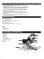
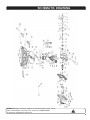
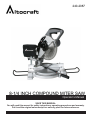
240-2087 8-1/4 INCH COMPOUND MITER SAW Operator’s Manual SAVE THIS MANUAL You will need this manual for safety instructions, operating procedures and warranty. Put it and the original sales receipt in a safe dry place for future reference. IMPORTANT SAFETY INSTRUCTIONS WARNING: When using electric tools, machines or equipment, basic safety precautions should always be followed to reduce the risk of fire, electric shock, and personal injury. ! READ ALL INSTRUCTIONS BEFORE USING THIS TOOL 1. KEEP WORK AREA CLEAN. Cluttered areas can cause injuries. 2. CONSIDER WORK AREA ENVIRONMENT. Don’t use power tools in damp, wet, or poorly lit locations. Don’t expose tools to the rain. Keep the work area well lit. Don’t use tools in the presence of flammable gases or liquids. 3. KEEP CHILDREN AND BYSTANDERS AWAY. All children should be kept away from the work area. Don’t let them handle machines, tools or extension cords. Bystanders can be a distraction and can be injuried. 4. GROUNDED TOOLS must be plugged into an outlet that is properly installed and grounded. Grounding provides a low-resistance path to carry electricity to the ground away from the operator, should the tool malfunction electrically. Do not remove the grounding prong from the plug or alter the plug in any way. If in doubt as to whether the outlet is properly grounded according to code, check with a qualified electrician. 5. OBSERVE PROPER PRECAUTIONS REGARDING DOUBLE INSULATION. This tool is double insulated. It is equipped with a polarized plug. One blade is wider than the other, so it will fit into a polarized outlet only one way. If you have difficulty inserting the plug, try reversing it. If it still doesn’t fit , do not alter the plug; have a qualified electrician install a polarized outlet. 6. GUARD AGAINST ELECTRIC SHOCK. Prevent body contact with grounded surfaces: pipes, radiators, ranges, and refrigerator enclosures. When your body is grounded the risk of electric shock increases. When working wherever “live” electrical wires may be encountered, try to ascertain whether there is a danger of shock. DO NOT TOUCH ANY METAL PARTS OF THE TOOL while using it. Hold the tool only by the plastic grip to prevent electric shock if you contact a live wire. 7. DO NOT MISUSE THE CORD. Never carry your tools by the cord or pull on the cord to unplug it. Protect the cord from potential sources of damage: heat, oil & solvents, sharp edges, or moving parts. Replace damaged cords immediately. 8. WHEN WORKING OUTDOORS, USE AN OUTDOOR-RATED EXTENSION CORD. An extension cord rated for outdoor use must be marked “W-A” or “W”. 9. DO NOT EXPOSE ELECTRICAL POWER TOOLS TO MOISTURE. Rain or wet conditions can cause water to enter the tool and lead to electric shock. 10. ENSURE THE EXTENSION CORD YOU USE IS OF SUFFICIENT GAUGE FOR ITS LENGTH. Recommended Minimum Wire Gauge for Extension Cords Amps from Tool Nameplate 0-5 amps 5.1-8 amps 8.1-12 amps 12.1-15 amps 15.1-20 amps 25’ length 16 ga. 16 ga. 14 ga. 12 ga. 10 ga. 50’ length 16 ga. 16 ga. 14 ga. 12 ga. 10 ga. 75’ length 16 ga. 14 ga. 12 ga. 10 ga. 10 ga. 100’ length 14 ga. 12 ga. 10 ga. 10 ga. Do Not Use 150’ length 12 ga. 10 ga. Do Not Use Do Not Use Do Not Use 11. STORE IDLE EQUIPMENT. Store equipment in a dry area to inhibit rust. Equipment also should be in a high location or locked up to keep out of reach of children. 12. DON’T FORCE THE TOOL. It will do the job better and more safely at the rate for which it was intended. 13. USE THE RIGHT TOOL. Don’t force a small tool or attachment to do the work of a larger industrial tool. Don’t use a tool for a purpose for which it was not intended. 14. DRESS PROPERLY. Don’t wear loose clothing or jewelry; they can be caught in moving parts. Protective, non-electrically conductive gloves, protective eyewear and non-skid footwear are recommended. Wear protective hair covering to contain long hair and keep yourself from harm. 2 200’ length 12 ga. Do Not Use Do Not Use Do Not Use Do Not Use IMPORTANT SAFETY INSTRUCTIONS 15. USE EYE PROTECTION. Use a full-face mask if the work you’re doing produces metal filings, dust or wood chips. Goggles are acceptable in other situations. Wear a clean dust mask if the work involves creating a lot of fine or coarse dust. 16. SECURE WORK. Use clamps or a vise to hold the work, this frees both hands to operate the tool. 17. DON’T OVERREACH. Keep proper footing and balance at all times. Do not reach over or across machines that are running. 18. MAINTAIN TOOLS. Keep tools sharp and clean for better and safer performance. Follow instructions for lubricating and changing accessories. For safe performance. Keep handles dry, clean and free from oil and grease. 19. AVOID UNINTENTIONAL STARTING. Be sure the switch is in the OFF position before plugging in. 20. ALWAYS CHECK AND MAKE SURE TO REMOVE ANY ADJUSTING KEYS OR WRENCHES before turning the tool on. Left attached, these parts can fly off a moving part and result in injury. 21. DO NOT USE THE TOOL IF IT CANNOT BE SWITCHED ON OR OFF. Have your tool repaired before using it. 22. DISCONNNECT THE PLUG FROM THE POWER SOURCE BEFORE MAKING ANY ADJUSTMENTS. Changing attachments or accessories can be dangerous if the tool could accidentally start. 23. STAY ALERT. Watch what you are doing & use common sense. Don’t operate any tool when you are tired. 24. CHECK FOR DAMAGED PARTS. Before using this tool, any part that is damaged should be carefully checked to determine that it will operate properly and perform its intended function. Check for alignment of moving parts, binding of moving parts, breakage of parts, mountings, and other conditions that may affect its operation. Inspect screws and tighten any ones that are loose. Any part that is damaged should be properly repaired or replaced by an authorized service center unless otherwise indicated elsewhere in the instruction manual. Have defective switches replaced by an authorized service center. Don’t use the tool if switch does not turn it on and off properly. 25. REPLACEMENT PARTS. When servicing, use only identical replacement parts. 26. SERVICE AND REPAIRS should be made by qualified repair technicians at an authorized repair center. Improperly repaired tools could cause serious shock or injury. SAFETY PRECAUTIONS FOR COMPOUND MITER SAW 1. WOOD ONLY. The saw is designed for woodcutting only. 2. DAMAGED OR WARPED SAW BLADES should not be used. They are out of balance and could cause further damage to the saw and possible personal injury. 3. USE ONLY WITH GUARD IN PLACE. The guard protects the operator from cutting debris as well as from broken pieces of the blade, should it break in use. 4. REPLACE THE TABLE INSERT WHEN WORN. Excessive tear-out increases the likelihood of injury from flying debris. When setting the saw at a new angle, check that the blade does not cut into the table insert, rear fence, or another part of your saw. 5. ALWAYS USE THE BLADE WRENCH to tighten the saw blade onto the arbor. 6. CONNECT YOUR MITER SAW TO A DUST COLLECTING DEVICE if possible. If not, use the dust bag that comes with the tool and empty it regularly. 7. USE A SAWBLADE SUITED TO THE CUTTING JOB AND MATERIAL TO BE CUT. SAFETY PRECAUTIONS FOR COMPOUND MITER SAW 8. ALWAYS USE TABLE EXTENSIONS AND CLAMPS to support the material when sawing long work pieces. 9. THE MATERIAL SHOULD BE PLACED FIRMLY AGAINST THE FENCE AND TABLE. The turning of the saw blade should force it down against the table and rearward against the fence during the cut. Movement of the workpiece during the cut may cause the blade jam and create a kickback. When this happens, the cutting head may jump out of your hand or the workpiece may fly loose and cause serious injury. 10. DO NOT START THE SAW WITH THE BLADE IN CONTACT WITH ANY SURFACE. This may cause the saw to bounce or kick back violently and could cause injury. 11. IF MAKING A CUT USING ONE HAND TO HOLD THE SAW, ensure the free hand is clear of the cutting area. SPECIFICATIONS = Voltage: 120 volts AC, 60Hz. = Current rating: 10 amps = No-load speed: 4800 rpm = 8-1/4” (210mm) 24 tooth carbide tipped saw blade = 5/8” (16mm) arbor = Bevel cuts up to 45° left = Miter cuts up to 45° left & right with detents at 0°, 15°, 22.5°, 30°, & 45° left and right Included: 1 dust bag 1 blade wrench 2 table side extensions 1 hold-down clamp FUNCTIONAL DESCRIPTION 1. 2. . 4. 5. 6. 7. 8. 9. 10. 11. Switch Brush cover Movable guard Saw blade Dust bag Bevel lock lever Hold-down clamp assembly Tabble extension Tabble extension lock screw Handle Miter scale 1 2 5 3 4 7 6 8 9 11 4 10 OPERATING PROCEDURES CAUTION! Be sure the saw is disconnected from its power source before making any repaires or performing maintenance! MOUNTING AND REMOVING THE BLADE 1. Loosen the movable guard release screw and rotate the guard center plate to expose the saw blade arbor screw. 2. Engage the spindle lock by pressing the pin located between the handle and the fixed guard. CAUTION: Never press the spindle lock pin while the saw is running! 3. Using protective gloves, rotate the blade by hand while pressing the pin until it engages a slot in the arbor. 4. While holding the spindle lock pin in, and using the supplied wrench, unscrew the arbor screw, remove the outside saw blade flange, and the saw blade. 5. When replacing the blade, apply the above procedure in reverse. 6. Be sure that when mounting the new saw blade, the direction arrows on the blade correspond with the arrow on the guard. CLAMPING WORKPIECE: WARNING: For safe and accurate cuts, affix workpiece firmly into cutting position with hold-down clamp, otherwise the tool and workpiece may be damaged. 1. Mount the hold-down clamp on one side of the fence. Insert the shaft of the hold-down clamp into the mounting hole and tighten the hold-down clamp retainer screw to affix the shaft of the hold-down clamp. 2. Adjust position of the hold-down clamp bracket according to the workpiece thickness and shape. Tighten the screw to affix the bracket in place. 3. Make sure that when the handle is lowered, bevelled or angled in any position, no part of the tool contacts the hold-down clamp. START UP USING YOUR SAW After unpacking, reading the instructions, attaching the machine to the workbench, and checking that all attachments are correctly installed, you can use your saw. Be sure to wear the appropriate protective equipment. 1. Check to ensure everything is correctly attached, screws are fastened, and all adjusting keys and wrenches are removed. 2. Connect the saw to a power source. 3. Unlock the saw from its various storage and shipping positions. 4. Pressing the trigger lock button, then squeezing the trigger switch in the handle, while holding the trigger lock button down, will start the saw The cutting head should be in the raised position and the blade fully enclosed in the guard before starting the miter saw. WARNING: Before plugging in saw, confirm that the trigger is working properly. If the locking button is not depressed, do not pull the trigger with force as this may cause severe damage to the switch. REMEMBER: Before use, release the head lock button and raise the handle. Before turning on, confirm that the saw blade does not touch the work piece or the vise at any position. When cutting, press the handle down slowly. DO NOT force the handle, as this may cause damage to your saw. Before starting to cut, confirm that the saw blade has attained full speed. After cutting is complete wait until the rotation of the blade STOPS completely before lifting the handle to its top position. For your safety, remove chips, small pieces, etc. from the table top before operation. For best performance, ALWAYS keep saw blade clean and sharp. 5 OPERATING PROCEDURES 5. To begin cutting, lower the cutting head. The movable guard opens automatically. 6. After cutting, allow the head to come back up. The guard will close automatically. 7. The saw will stop when you release the trigger switch. MODES OF USE Chop cut: The head is locked in the upright position. The table rotation is locked at 0°. This is a good setting for simple 90° crosscuts. Miter cut: The head is locked in the upright position. To unlock the table rotation, unscrew the locking handle and press on the miter detent spring lever with your thumb Move the table rotation to the left or right up to 45° left & 52° right. The miter detent spring lever , if released, will stop the table at detents at 0°, 15°, 22.5°, 30°, & 45° left and right. Use the locking handle to lock the table at the desired angle, especially those in between the detents. Bevel cut: To unlock the head angle (bevel) adjustment, loosen the bevel lock handle at rear of the saw. Lock it when the blade is tilted at the desired angle. The table rotation is locked at 0°. Compound cut: Unlock and move the table rotation to the left or right as in miter cuts above. Using the lever at the back of the saw, unlock the head and bevel it to any position from 0° – 45° left, then lock it in place. NOTE: At extreme positions, the hold-down clamp should be moved to the right side of the table to prevent interfering with the movement of the cutting head. Always check before making the cut if there is any potential interference from the clamp or any other part of the machine. MAINTENANCE NOTE: Even though the angles are marked on the machine, it is always a good idea to check them by making a trial cut. See Aligning Miter and Bevel, below. Inspect the cord regularly and have it replaced by an authorized repair facility if it is damaged. Check the brushes occasionally (after about 50 hours of use) and replace if worn. The brushes can be replaced by removing the motor cap. The brushes and their springs could jump out of the holders- be careful not to lose them. Inspect the brushes. If the contact surface is not smooth, or it is worn or heavily used, replace both brushes. Insert the new brushes and springs in their holders and re-fasten the cap. The plastic kerf plate table insert should be replaced if damaged to reduce the risk of chips lodging in the slot and catching in the blade. Keep the vents clear of dust and debris. This will help prevent possible electrical shorts and ensure proper cooling. Keep the tool housing and handle clean and free of oil and grease by using mild soap and a damp (not wet) cloth. 6 MAINTENANCE ALIGNING MITER AND BEVEL Miters and bevels have been set at the factory. However, use may effect settings. Please use the following procedures when your tool needs adjustments. Miter Angle 1. Set the bevel angle at 0 degree. 2. Loosen the locking handle. 3. Depress the miter detent spring lever. 4. Turn the saw table so that the arrow in the kerf plate points to 0 degree, then move the table slightly clockwise and counter-clockwise and let the miter detent spring lever fit into the groove (it doesn’t matter if needle doesn’t indicate 0 degree ). 5. Loosen the four hex bolts behind the fence with the blade socket wrench. 6. Lower the saw head and lock it in place with the head lock button. 7. Use the clear plastic setup triangle to check that the saw blade and the fence are square. Move the fence a few millimeters to achieve this if necessary. 8. Tighten the hex bolts in the fence firmly. 9. Confirm that the arrow in the kerf plate points to 0 degree. If not, loosen the two screws in the bottom of the miter detent spring lever and adjust accordingly. Bevel Angle A. Vertical stop: 0 degree adjustment 1. Lower saw head to lowest position and lock it with the head lock button. 2. Loosen the bevel lock handle on the back of the saw. 3. Check that the blade is perpendicular to the table as measured by the clear plastic setup triangle. If not : Use an open-end wrench to loosen the hex lock nut at the back left side of the table. b. Turn the bolt counter-clockwise and the 0 point moves left, closing the angle. Turning it clockwise moves the 0 point to the right, opening the angle. c. When you have established the vertical stop correctly, tighten the lock nut to hold the setting. d. Make sure that the needle points to 0 degree on the scale. If not, loosen the screws and adjust the needle. a. B. 1. 2. 3. Bevel stop: 45 degrees adjustment Lower the saw head to lowest position and lock it with the head lock button. Loosen the bevel lock handle on the back of the saw. Check that the blade is at 45 degrees to the table as measured by the clear plastic setup triangle. If not : a. Use an open-end wrench to loosen the hex lock nut at the back left side of the table. b. Turn the bolt clockwise and the 45 degrees point moves left, opening the angle. Turning it counter-clockwise moves the 45 degrees stop to the right, closing the angle. c. When you have established the 45 degrees stop correctly, tighten the lock nut to hold the setting. d. Make sure that the needle points to 45 degrees on the scale. If not, loosen the screws and adjust the needle. PARTS LIST Please refer to the schematic drawing on page 9. No. 1. Description Cover screw No. 42. Description Bearing cover No. 83. Description Screw 2. Driving plate 43. Upper handle 84. Nut 3. Ring 44. Locking pole 85. Screw 4. Needle bearing 45. Spring 5. Screw 46. Switch 86. 87. Support fence Cushion 6. Lower blade guard 47. Screw 7. Spring 48. Switch cover 88. 89. Lock-screw Screw 8. Screw 49. Wind guard 9. Locating plate 50. Stator 90. 91. Table insert Screw 10. Locknut 51. Tapping screw 92. Swivel table 11. Bolt 52. House 93. Nut 12. Outer blade clamp 53. Washer 94. Base 13. Saw blade 54. Spring washer 95. Screw 14. I nner blade clamp 55. Screw 96. Bracket 15. 16. Gear shaft Semi-circle key 56. 57. Tapping screw Brush holder 97. 98. Screw Spring 17. Screw 58. Carbon brush 99. Steel ball 18. Spring washer 59. Brush holder cap 100. Screw 19. Washer 60. Aluminum protective 101. Screw 20. Bearing cover 61. Specification plate 21. Bearing 62. Tapping screw 102. Washer 103. Locknut 22. Gear box cover 63. Cable pressboard 104. Finger 23. Big gear 64. Cable clip 105. Bracket 24. Spindle clip 65. Cable 106. Handle 25. Oiled copper sleeve 66. Locking knob 107. Handspike 26. Spindle clip 67. Pin shaft 108. Screw 27. Washer 28. Lock-screw 68. 69. Sleeve for screw Screw 109. Wire holder 110. Dust collecting bag 29. Bracket clamp 70. Spring 30. Lock-screw 71. Spindle 111. Brand name plate 112. Socket spanner 31. Clamp pole 72. O-ring 32. Screw 73. Knob 33. Guard cover 74. Saw arm 34. Lock-screw 35. Rubber ring 75. 76. Pivot pen Washer 36. Screw 77. Spring washer 37. Guard cover 78. Screw 38. Screw 79. Lock-screw 39. Bearing 80. Square bolt 40. Rotor 81. Spindle 41. Bearing 82. Arm base 8 SCHEMATIC DRAWING WARNING Repairs should be made by an authorized repair center. Do not open or disassemble this power tool . Contact at 1-866-915-8626 for questions regarding this power tool. ! 9