1
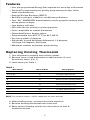
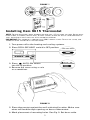
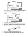
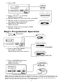
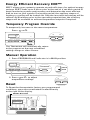
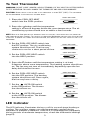
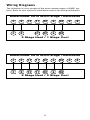
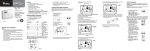
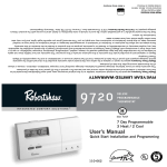
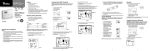
9615
®
INTEGRATED COMFORT SOLUTIONS™
DIGITAL
PROGRAMMABLE
THERMOSTAT
E
G
ELECTRIC
GAS
7 Day Programmable
2 Heat / 2 Cool
User’s Manual
Quick Start
Installation and
Programming
WA
110-737
As an Energy Star partner, Maple Chase has
determined that this thermostat product meets
the Energy Star guidelines for energy efficiency.
RRANTY
©1999 Maple Chase Company
Important Safety Information Warning:
• Always turn off power at the main power source by unscrewing
fuse or switching circuit breaker to the off position before installing,
removing, cleaning or servicing thermostat.
•
Read all of the information in this manual before installing or
programming this thermostat.
•
This is a 24V AC low-voltage thermostat. Do not install on voltages
higher than 30V AC.
•
All wiring must conform to local and national building and electrical
codes and ordinances.
•
Do not short (jumper) across terminals on the gas valve or at the
system control to test installation. This will damage the thermostat
and void the warranty.
1
Features
• Four pre-programmed Energy Star setpoints for each day of the week
• Quickset™ programming for quickly programming all days of the
week simultaneously
• Energy Efficient Recovery (EER™)
• Residual cooling for added air-conditioning efficiency
• Two “AA” ENERGIZER brand batteries retain program memory, even
during power outages
• Low battery indicator
• LED indicator for auxiliary system operation
• Zone compatible as master thermostat
• Fahrenheit/Celsius display option
• Programmable from 45°F (7°C) to 90°F (32°C)
• Accuracy within ±1 degrees
• Adjustable 1st and 2nd stage differential: 1-3 degrees,
1st stage: 2-6 degrees, 2nd stage
• Maintains summer and winter programming
Replacing Existing Thermostat
1. Turn off power to heating and cooling system.
2. Remove cover of old thermostat to expose wires. Do not
disconnect wires. (Fig. 1)
3. Label wires per Table 1.
TABLE 1
Old Label
New Label
Description
R, V-VR or VR-R
R
24 VAC
Y, Y1 or M
Y1
1st Stage Cooling Circuit
O or R
O
Reversing Valve (Cooling Mode)
B
B
Reversing Valve (Heating Mode)
G or F
G
Fan Contactor Circuit
Y2
Y2
2nd Stage Cooling Circuit
W2 or W-U
W2
2nd Stage Heating Circuit
W1
W1
C, X or B
1st Stage Heating Circuit
C
24 VAC, Transformer Common Side
NOTE: THIS THERMOSTAT REQUIRES A 24V AC COMMON WIRE FOR PROPER OPERATION.
4. After labeling wires, remove wires from terminals.
5. Remove existing thermostat base from wall.
6. Refer to the following section for instructions on how to
install thermostat.
2
FIGURE 1
Installing Item 9615 Thermostat
NOTE: FOR NEW INSTALLATIONS, MOUNT THERMOSTAT ON INSIDE WALL, 4-5 FEET ABOVE THE FLOOR. DO NOT INSTALL
BEHIND A DOOR, IN A CORNER, NEAR AIR VENTS, IN DIRECT SUNLIGHT, OR NEAR ANY HEAT OR STEAM GENERATING FIXTURES. INSTALLATION AT THESE PLACES WILL AFFECT THERMOSTAT OPERATION.
IMPORTANT: THIS THERMOSTAT IS COMPATIBLE WITH 100% LOCKOUT SYSTEMS. TO RESET THE SYSTEM, TURN
THERMOSTAT TO OFF POSITION FOR AT LEAST 60 SECONDS.
1. Turn power off to the heating and cooling systems.
2. Place COOL-OFF-HEAT switch in OFF position.
COOL-OFF-HEAT
PROG
MAN
>
>
AUX
SET PROG/MAN
COOL-OFF-HEAT
AUTO - ON
AUTO - ON
3. Place
AUTO-ON switch
into AUTO position.
4. Remove the cover using a coin
or screwdriver.
FIGURE 2
5. Place thermostat against the wall at desired location. Make sure
wires will feed through opening on base of thermostat.
6. Mark placement of mounting holes. See Fig. 3. Set base aside.
3
FIGURE 3
MOUNTING HOLES
C
PROG
MAN
MORN DAY EVE NITE EER
CHANGE
SET
R
Y2 Y1 W1 W2
AM
PM
G
PROG/MAN
O
B
COOL OFF HEAT
FAN AUTO ON
7. Drill the marked holes using a 3/16" drill bit. NOTE: Enclosed plastic
anchors do not require a drilled hole for drywall.
8. Tap plastic anchors into the holes.
9. Align base with plastic anchors and feed wires through opening.
See Fig 4.
FIGURE 4
OPENING
C
PROG
MAN
MORN DAY EVE NITE EER
CHANGE
SET
PROG/MAN
R
Y2 Y1 W1 W2
AM
PM
G
O
B
COOL OFF HEAT
FAN AUTO ON
10. Secure base to wall with supplied screws.
11. Connect wires to terminal strip. Refer to wiring diagrams on other
side of this sheet. Make sure wire connections are secure.
12. Install two "AA" ENERGIZER brand batteries or equivalent into battery compartment. Be sure to match positive (+) ends of batteries
with positive (+) battery terminals in the battery compartment.
13. Replace cover onto thermostat by snapping into place.
14. Turn on power to system. Test thermostat as described in the
following section.
4
Programming Guide
Set Time of Day, Day of Week,
Temperature Differential,
Residual Cooling
1. Press SET & PROG/MAN.
Release simultaneously.
SET PROG/MAN
PROG
MAN
AUTO - ON
>
COOL-OFF-HEAT
Press
or
Time of Day.
to change
Press
>
2. Press
>
>
>
>
>
>
AUX
SET PROG/MAN
SET P
1=MO
2=TU
3=WE
4=TH
5=FR
6=SA
7=SU
To Change
Day of Week
Press
>
SET P
>
3. Press
To change 1st Stage
Temperature Differential
NOTE: THE TEMPERATURE DIFFERENTIAL
IS
FACTORY
PRESET AT
1°. THIS
MEANS
THAT WHENEVER THE ROOM TEMPERATURE CHANGES BY ONE FULL DEGREE FROM
THE TEMPERATURE SETTING, THE SYSTEM WILL TURN ON. IF THE SYSTEM TURNS
ON TOO OFTEN, INCREASE THE TEMPERATURE DIFFERENTIAL.
Press
>
SET P
>
4. Press
To change 2nd Stage
Temperature Differential
NOTE: SECOND
STAGE DIFFERENTIAL IS FACTORY PRESET AT
5
2°.
>
Press
>
5. Press
SET P
To change
Residual Cooling
NOTE: THE RESIDUAL COOL FEATURE WILL KEEP THE SYSTEM FAN ON FOR AN
ADDITIONAL 30, 60 OR 90 SECONDS AFTER THE COMPRESSOR CYCLES OFF.
THE RESIDUAL COOL FEATURE CAN ONLY BE SET IN THE COOL MODE.
Changing Fahrenheit (F) to Celsius (C)
Press
>
Press and Hold SET
SET P
Release both simultaneously.
QuickSet™ Programming Mode
COOL-OFF-HEAT
PROG
MAN
>
>
AUX
SET PROG/MAN
COOL-OFF-HEAT
AUTO - ON
SET P
>
>
1. Place COOL-OFF-HEAT
in COOL or HEAT position.
2. Press & Hold SET. Press the
Release simultaneously.
button.
3. The MORN indicator should be blinking. Program the Time-of-Day and
the temperature as outlined in the Setting Daily Program section.
NOTE: QuickSet™ will program all 7 days of the week with the same program.
Setting Daily Programming
1. Place COOL-OFF-HEAT
in COOL position.
COOL-OFF-HEAT
PROG
MAN
AUTO - ON
SET PR
>
3. Press SET. Press
MORN time
>
>
>
2. Press SET button. The display will
show a number from 1 to 7. This
number represents the day of the
week to be programmed. If programming individual days, press
either
or
button to adjust
the day of the week to program.
or
to change
6
>
COOL-OFF-HEAT
>
>
>
AUX
SET PROG/MAN
4. Press SET.
SET PR
PROG
MAN
AUTO - ON
>
COOL-OFF-HEAT
>
>
>
>
>
AUX
SET PROG/MAN
5. Press
or
to change
MORN temperature.
6. Repeat Steps 2-5 for DAY, EVE, and NITE.
7. Repeat steps 2–6 above to program
any other day of the week.
COOL-OFF-HEAT
8. Shift COOL-OFF-HEAT to
HEAT position.
9. Repeat steps 2-6 to program HEAT
(winter) settings.
Begin Programmed Operation
1. Place
AUTO/ON
into AUTO.
AUTO - ON
PROG
MAN
>
>
AUX
SET PROG/MAN
COOL-OFF-HEAT
AUTO - ON
COOL-OFF-HEAT
SUMMER
2. Place COOL-OFF-HEAT
into COOL or HEAT
Depending upon the season.
COOL-OFF-HEAT
WINTER
3. Press PROG/MAN button
until indicator is in
PROG position.
ET PROG/MAN
C
PROG
MAN
>
>
AUX
SET PROG/MAN
COOL-OFF-HEAT
AUTO - ON
PROG
MAN
NOTE: WHILE IN THE COOL MODE ONCE THE THERMOSTAT TURNS THE SYSTEM OFF, A BUILT-IN DELAY KEEPS THE
COMPRESSOR FROM TURNING ON FOR ABOUT 5 MINUTES. THIS PROTECTS THE COMPRESSOR. NO ADDITIONAL TIME
DELAY RELAY (DELAY ON BREAK) IS NECESSARY. TO OVERRIDE THE 5-MINUTE DELAY FOR INSTALLATION, PRESS
RESET. THIS WILL ERASE THE DELAY AS WELL AS ALL PROGRAMMING.
7
Energy Efficient Recovery EER™
EER™ allows your system to operate at peak efficiency for optimal energy
savings. EER™ looks up to 2 hours prior to the end of a set-back period to
begin monitoring system performance and determine the most efficient
time to turn on your system. During this period, the auxiliary stages of
heating or cooling will be locked out. Only the most efficient stages will be
utilized. At 20 minutes prior to the upcoming setpoint time, the auxiliary
stages will be available to achieve temperature setpoint if required.
Temporary Program Override
>
PROG
>
or
>
Press
>
To temporarily increase or decrease temperature
MAN
>
>
AUX
SET PROG/MAN
COOL-OFF-HEAT
AUTO - ON
The Thermostat will automatically return
to the program at the next scheduled
setting change or after 4 hours.
Manual Operation
1. Press PROG/MAN until indicator is in MAN position.
PROG
MAN
AUX
>
>
T PROG/MAN
SET PROG/MAN
COOL-OFF-HEAT
PROG
AUTO - ON
>
2. Press or
to adjust
temperature settings.
Reset
To Reset the thermostat to factory pre-programmed
conditions, press the reset button located directly
to the right of the display.
RESET BUTTON
C L R
PROG
MAN
MORN DAY EVE NITE EER
CHANGE
SET
PROG/MAN
Y2 Y1 W1 W2
AM
PM
G
O
B
COOL OFF HEAT
FAN AUTO ON
8
>
>
>
MAN
To Test Thermostat
WARNING: DO NOT SHORT (JUMPER) ACROSS TERMINALS OF GAS VALVE OR SYSTEM CONTROL
TO TEST OPERATION. THIS WILL DAMAGE THE THERMOSTAT AND VOID YOUR WARRANTY.
CAUTION: DO NOT SWITCH SYSTEM TO COOL IF THE TEMPERATURE IS BELOW 50°F (10°C). THIS CAN DAMAGE
THE AIR CONDITIONING SYSTEM AND CAUSE PERSONAL INJURY.
1. Place the COOL-OFF-HEAT
switch into the COOL position.
COOL-OFF-HEAT
>
2. Press the button until the temperature
setting is at least 3 degrees below the room temperature. The air
conditioning system should turn on within a few seconds.
NOTE: WHILE IN THE COOL MODE ONCE THE THERMOSTAT TURNS THE SYSTEM OFF, A BUILT-IN DELAY KEEPS THE COMPRESSOR
FROM TURNING ON FOR ABOUT 5 MINUTES. THIS PROTECTS THE COMPRESSOR. NO ADDITIONAL TIME DELAY RELAY (DELAY ON BREAK)
IS NECESSARY. TO OVERRIDE THE 5-MINUTE DELAY FOR INSTALLATION, PRESS RESET. THIS WILL ERASE THE DELAY AS WELL AS ALL
PROGRAMMING.
3. Put the COOL-OFF-HEAT switch into
the OFF position. The air conditioning
system should turn off. The fan may
continue to run for a short period of time.
COOL-OFF-HEAT
COOL-OFF-HEAT
>
4. Put the COOL-OFF-HEAT switch
into the HEAT position.
5. Press the button until the temperature setting is at least
3 degrees above room temperature. The heating system should turn
on. The fan may not turn on immediately, depending upon the fan
delay built into the furnace.
6. Put the COOL-OFF-HEAT switch
into the OFF position. The heating
system should turn off. Once again,
the fan may have a delay.
COOL-OFF-HEAT
AUTO - ON
7. Put the
AUTO-ON switch
to the ON position. The blower
fan should turn on.
AUTO - ON
8. Put the
AUTO-ON switch
to the AUTO position. The blower
fan should turn off.
LED Indicator
The LED indicator illuminates during a call for second stage heating or
cooling. The auxiliary stages are used to maintain comfort during
extremes in weather conditions. If the LED is illuminated too frequently
during periods of moderate temperature, check the differential settings
(page 5).
9
Troubleshooting
SYMPTOM
REMEDY
Thermostat does not turn
on system.
Check Wiring.
(See “INSTALLATION.”)
Check fuse. Replace with 3 amp
fuse if fuse has opened. Five
minute compressor short cycle
protection may be in effect. Press
RESET to override. NOTE: This will
erase programming.
Thermostat turns on and off too
frequently.
Increase Temperature Differential
(See “PROGRAMMING.”)
Display is blank, flashing or
constant "LO BAT".
Replace batteries.
System fan does not operate
properly.
Move fan option switch to either
gas or electric, to match system.
(See “INSTALLATION.”)
Time shown on display is not the
current time of day.
Change time of day setting.
(See “PROGRAMMING.”)
Thermostat does not follow
program.
Thermostat in MANUAL mode. (See
“PROGRAMMING.”)
Thermostat may not have been programmed in HEAT or COOL position.
Verify program.
Check AM/PM indicators at time of
day and programmed time changes.
(See “PROGRAMMING.”)
Verify program and day of week
are correct. (See “PROGRAMMING.”)
Thermostat does not advance day
of week.
To view or change day of week,
use method on page 5.
If problems with thermostats cannot be solved, call:
Technical Support: (800) 445-8299
Monday-Friday 7:30-5:30 CST
For warranty returns, send thermostat, shipping prepaid to:
Uni-Line North America
Warranty Claims Department
515 S. Promenade
Corona, CA 91719
10
Wiring Diagrams
The following is just a sample of the most common types of HVAC systems. Refer to your system’s installation manual for wiring information.
Robertshaw 9615 Multi-Stage Thermostat
C
R
C
R
Y2
Y1
W1
G
W2
Y/Y1 W1
G
W2
O
B
2 Stage Heat / 1 Stage Cool
Robertshaw 9615 Multi-Stage Thermostat
C
R
Y2
Y1
W1
G
W2
C
R
Y2
Y1
W1
G
W2
2 Stage Heat / 2 Stage Cool
11
O
B
Five-Year Limited Warranty
Maple Chase Company warrants to the original contractor installer, or to the original consumer user, each new
Robertshaw thermostat to be free from defects in materials and workmanship under normal use and service for a period
of five (5) years from date of purchase. This warranty does not cover batteries, damage caused by batteries, damage
resulting from improper installation, alteration, misuse or abuse of the thermostat occurring after the date of purchase.
Maple Chase Company agrees to repair or replace at its option any thermostat under warranty provided it is returned
within the warranty period, postage prepaid, with proof of the date of purchase. Cost of thermostat removal or reinstallation is not the responsibility of Maple Chase Company.
Repair or replacement as provided under this warranty is the exclusive remedy of the consumer. Maple Chase Company
shall not be liable for any incidental or consequential damages for breach of any express or implied warranty on this
product, or under any other theory of liability. Except to the extent prohibited by applicable law, any implied warranty of
merchantability or fitness for a particular purpose on this product is limited to the duration of this warranty.
Some states do not allow the exclusion or limitation of incidental or consequential damages, or allow limitations on how
long an implied warranty lasts, so the above limitations or exclusions may not apply to you. This warranty gives you specific legal rights, and you may also have other rights which vary from state to state.
Maple Chase Company
2820 Thatcher Road
Downers Grove, Illinois 60515
United States of America