1
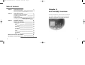
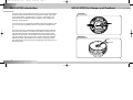
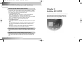
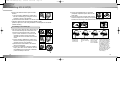
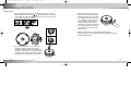
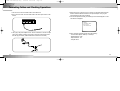
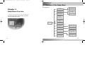
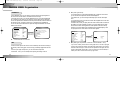
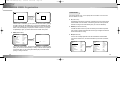
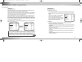
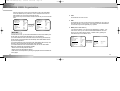
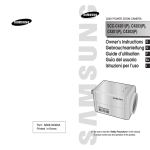
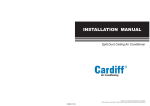
00326A SCC-931T(P)-eng
9/25/02 12:30 PM
Page 1
ANTI-VANDAL DOME CAMERA
SCC-931T(P)
User’s Manual
GB
Bedienungsanleitung
D
Guide de l’utilisateur
F
Guía del Usuario
Manuale d’uso
Es
I
00326A SCC-931T(P)-eng
9/25/02 12:30 PM
Page 2
Important Safety Instructions
CAUTION
RISK OF ELECTRIC
SHOCK DO NOT OPEN
CAUTION: TO REDUCE THE RISK OF
ELECTRIC SHOCK, DO NOT
REMOVE REAR COVER. NO
USER SERVICEABLE PARTS
INSIDE. REFER TO QUALIFIED
SERVICE PERSONNEL.
This symbol indicates high voltage
is present inside. It is dangerous
to make any kind of contact with
any inside part of this product.
This symbol alerts you that
important literature concerning
operation and maintenance has
been included with this product.
To prevent damage which may result in fire or electric shock hazard, do not expose this
appliance to rain or moisture.
This device complies with part 15 of the FCC Rules. Operation is subject to the
following two conditions.
Read these instructions.
2.
Keep these instructions.
3.
Heed all warnings.
4.
Follow all instructions.
5.
Do not use this apparatus near water.
6.
Clean only with dry cloth.
7.
Do not block any ventilation openings. Install in accordance with the
manufacturer’s instructions.
8.
Do not install near any heat sources such as radiators, heat registers, or other
apparatus (including amplifiers) that produce heat.
9.
Do not defeat the safety purpose of the polarized or grounding-type plug. A
polarized plug has two blades with one wider than the other. A grounding type
plug has two blades and a third grounding prong. The wide blade or the third
prong are provided for your safety. If the provided plug does not fit into your
outlet, consult an electrician for replacement of the obsolete outlet.
1) This device may not cause harmful interference, and
10. Protect the power cord from being from being walked on or pinched particularly
at plugs, convenience receptacles, and the point where they exit from the
apparatus.
2) This device must accept any interference that may cause undesired operation.
11. Only use attachments/accessories specified by the manufacturer.
CAUTION:
12. Use only with cart, stand, tripod, bracket, or table specified by the manufacturer,
or sold with the apparatus. When a used, caution when moving the
cart/apparatus combination to avoid injury from tip-over.
Danger of explosion if battery is incorrectly replaced.
13. Unplug this apparatus. When a cart is used, use caution when moving the
cart/apparatus combination to avoid injury from tip-over.
Replace only with the same or equivalent type recommended by the manufacturer.
Dispose of used batteries according to the manufacturer’s instructions.
2
1.
14. Refer all servicing to qualified service personnel. Servicing is required when the
apparatus has been damaged in any way, such as power-supply cord or plug is
damaged, liquid has been spilled or objects have fallen into the apparatus, the
apparatus has been exposed to rain or moisture, does not operate normally, or
been dropped.
3
00326A SCC-931T(P)-eng
9/25/02 12:30 PM
Page 4
Table of Contents
Chapter 1
Chapter 2
Chapter 3
SCC-931T(P) Overview
5
SCC-931T(P) Introduction
SCC-931T(P) Part Names and Functions
6
7
Installing SCC-931T(P)
9
Checking the Contents of the Package
Precautions for Installation and Use
Preparing Cables
Installing SCC-931T(P)
Connecting Cables and Checking Operations
10
12
14
15
22
Setup Menu Overview
24
Structure of the Setup Menu
CAMERA MENU Organization
CAMERA ID
IRIS
AUTO FOCUS
SHUTTER
AGC/MOTION
WHITE BAL
SYNC
SPECIAL
MOTION DET
EXIT
25
26
26
26
29
30
31
32
34
34
38
39
External Connector Pin Specifications
SCC-931T(P) - Product Specifications
4
Chapter 1
SCC-931T(P) Overview
This chapter briefly introduces the SCC-931T(P) and
describes its key features, part names and functions.
40
41
5
00326A SCC-931T(P)-eng
9/25/02 12:30 PM
Page 6
SCC-931T(P) Introduction
The SCC-931T(P) Anti-Vandal Dome Camera is a dome-typed surveillance
device that offers the best features of surveillance for banks, retail stores,
commercial buildings, industrial settings, and etc. It is designed to withstand intentional or accidental impact or vandalism, and is waterproof,
dustproof, and shockproof.
SCC-931T(P) Part Names and Functions
Front View
The SCC-931T(P) is an advanced surveillance device that enables a maximum of 120x zoom surveillance with its 12x zoom lens and digital zoom
IC.
The SCC-931T(P) is a multifunction surveillance device that is equipped
with all of the key features of the existing surveillance cameras: the LowLight Surveillance function that enables shooting moving objects under
extremely low illumination, the White Balance function that provides accurate color rendition under any light source, the BLC function that enables
effective back light compensation even at locations with bright incident
light, and the Auto Focus function that automatically tracks and focuses on
the moving subject.
6
Rear View
BNC
POWER
7
00326A SCC-931T(P)-eng
9/25/02 12:30 PM
Page 8
SCC-931T(P) Part Names and Functions
❶ Camera Operation Switches (Setup Switches)
The functions of the camera operation switches change depending on whether
the SCC-931T(P) is currently in the usual operation mode (i.e., the setup menu
is not showing on the screen) or the setup menu mode.
➻ In the usual operation mode
- [UP/DOWN] Directional keys: The [UP] key is used as the ZOOM TELE
switch, and the [DOWN] key is used as the ZOOM WIDE switch.
- [LEFT/RIGHT] Directional keys: The [LEFT] key is used as the FOCUS NEAR
switch, and the [RIGHT] key used as the FOCUS FAR switch.
- [ENTER] key: This key is used to go into the setup menu.
Chapter 2
Installing SCC-931T(P)
This chapter explains what to check before installing the
SCC-931T(P), how to choose an installation site, and what
precautions should be taken during installation. Now, let’s
install the SCC-931T(P) and connect cables.
➻ In the setup menu mode
- [UP/DOWN] Directional keys: These keys are used to move the cursor up and
down.
- [LEFT/RIGHT] Directional keys: These keys are used to move the cursor left
and right, or to sequentially view the values that can be assigned in each
setup menu.
- [ENTER] key: This key is used to select a setup menu with a submenu in
order to open the submenu, and to accept the current value.
❷ Power Input Connector and Video Output Connector (5-Pin)
These connectors are used to connect the power adapter cable and video input
cable.
❸ RS485 Connector and Alarm Output Connector (4-Pin)
These connectors are used to connect an RS485 remote control cable and a
cable used for transmitting the ALARM signal at the time of the MOTION DET
mode.
8
9
00326A SCC-931T(P)-eng
9/25/02 12:30 PM
Page 10
Before Installation
Checking the Contents of the Package
Be sure to check that the following items are included in the package.
✔ PLASTIC ANCHOR 2 ea. ❙ for ceiling installation
✔ ASSY SCREW TAPPING 2 ea. ❙ for ceiling installation
(TH M4 X L30 BLK + 0 RING)
Us
er’s
SCC-931T(P)
Gu
ide
User’s Guide
✔ ASSY SCREW MACHINE 2 ea. ❙ Attach to the holes at the
bottom for waterproof protection when installing the
camera on a pipe (CH M5 L8 XM7 + 0 RING)
✔ L WRENCH 1 ea. ❙ for COVER DOME removal
✔ DECORATION-MOUNT 1 ea. ❙ for covering the gap between
the ceiling and the PIPE when fastening using the PIPE
(ABS 94 V0)
ALARM & RS485 Cable
10
✔ TEMPLET 1 ea. ❙ An installation GUIDE for installing
on a ceiliing (ART PAPER)
11
00326A SCC-931T(P)-eng
9/25/02 12:30 PM
Page 12
Before Installation
Precautions for Installation and Use
SCC-931T(P) - Installation Examples
✔ Please check whether the installation site can sufficiently support the weight of
the SCC-931T(P) before installation.
✔ It can be directly installed on ceilings.
✔ It can be directly installed on pipes coming down from the ceiling.
✔ Make sure that the cable is not caught on anything or its insulation sheath is
not removed. (Neglecting to do so may cause fire or damage to the product.)
✔ Prevent people from approaching the installation area, where objects might fall
during installation. Move valuables to a safe location before installation.
✔ Install in a cool place and away from direct sunlight.
Be sure not expose the SCC-931T(P) to direct sunlight even during use or
storage. Use the BLC function when operating the SCC-931T(P) underneath a
spot light or under very bright lights.
✔ It can be directly installed on walls.
✔ It can be directly installed on pipes protruding from the wall.
✔ It can also be installed on corners of the building or on columns by using a
WALL MOUNT ADAPTER (SADT-101WM), CONER MOUNT ADAPTER
(SADT-110CM), or POLE MOUNT ADAPTER (SADT-100PM).
(These items are sold separately.)
✔ Use only in an area where temperature and humidity are kept within the limits
specified below:
- Operating Temperature: -10°C ~ +50°C (14°F~122°F)
- Humidity: Below 90%
✔ Use only the power source specified below:
- Power Consumption: 6W
- Voltage: DC 12V 600mA, AC 24V 300mA
12
13
9/25/02 12:30 PM
Page 14
Installing SCC-931T(P)
Power Adapter Cable
The power adapter that plugs
into the SCC-931T(P)’s power
input receptacle has the rated
voltage of DC 12V 600mA or
AC 24V 300mA.
Video Cable
The cable that connects the
video output terminal of the
SCC-931T(P) to the monitor is a
BNC cable.
For installing directly on a ceiling
1. Choose an installation site that can sufficiently support the weight of the equipments to be installed.
2. Attach the supplied template to the installation site, drill pilot holes (5 mm diam
eter, min. 35 mm depth), and then install and secure the supplied plastic
anchors (HUD 5).
3. Connect the power cord and video cable, and arrange them so that they will not
be damaged or caught when installing the CAMERA.
4. Remove the DOME COVER to install the CAMERA.
1) Use the supplied L WRENCH to unfasten the 4
BOLTS for CASE fixing by turning them counterclockwise as shown in the illustration.
2) Disassemble the ASSY-DOME in the direction
shown in the illustration.
5. Install the CAMERA.
Align the CAMERA’s installation holes to the
holes where the PLASTIC ANCHORS are
inserted and then fasten the ASSY SCREWTAPPINGS (TH M4 X 30) with O RINGS.
(2 spots) (It will not be waterproof without O
RINGS.)
14
1)
2)
SUNG
The following cables are required to install and use the SCC-931T(P).
SAM
Preparing Cables
➜
00326A SCC-931T(P)-eng
15
00326A SCC-931T(P)-eng
9/25/02 12:30 PM
Page 16
Installing SCC-931T(P)
For installing on a pipe
6. Adjust the LENS direction.
1) Turn the STOPPER RING counter-clockwise as shown in the
illustration to move the LENS body and COVER LENS.
2) Move the LENS body to adjust the vertical direction and turn
the LENS body together with the COVER
LENS to adjust the horizontal direction.
(There is a stopping mechanism on the
COVER LENS so that the LENS cannot be
turned more than 180° degrees to either left or right.
COVERLENS
BODY
Excesive rotation of the LENS may twist the inside wiring LENS
STOPPERand cause damage such as a short circuit or broken wire.)
RING
☛ The BOTTOM marking of the LENS must face downward.
(Otherwise, the image may look tilted or inversed.)
3) Position the LENS in the desired direction, hold the COVERLENS with one hand, and tightly fasten the STOPPER RING
clockwise with the other hand so that the LENS is not loose.
7. If the interior and exterior of the DOME is dirty, wipe off dirt with
a soft cotton flannel cleaning cloth.
8. After assembling the DOME COVER in the correct
direction, fasten the CASE fixing BOLT by turning it
clockwise with a L WRENCH. (4 spots)
16
1. Choose an installation site that can sufficiently sup
port the weight of the equipments to be installed.
2. Fasten the supplied ASSY SCREW MACHINE
(CH M5 L8 XM7 + 0 RING) in each of the two spots
to prevent water or dust from entering the unit.
SCREW
MACHINE
For installing on a pipe coming down from the ceiling
3. Fit the DECORATION MOUNT into the PIPE. (A DECORATION MOUNT is used
to conseal the hole in finished ceiling when installing indoor.)
4. Connect the power cable and video cable.
5. After arranging the connected power cable and
video cable inside the PIPE and then pulling them
out, put together the CAMERA’s PIPE assembly
screw (3/4” Threaded) and the PIPE’s screw (3/4”
Threaded) to fasten the SET. (*Wrap a TEFLON
TAPE around the threaded area of the PIPE to make
the connection watertight, and make sure that the
cables are not caught by the fastening area.)
Concrete
Ceiling
CEILING
BOARD
PIPE(3/4”
Threaded)
TEFLON
TAPE
DECORATION
MOUNT
17
00326A SCC-931T(P)-eng
9/25/02 12:30 PM
Page 18
Installing SCC-931T(P)
5) Remove the CAMERA body from the CASE.
(Completely separate the power cable from the
video cable.)
6) Disconnect the power and video cables from the
PCB and arrange them so that they can be passed through the PIPE
assembly hole on the side of the CASE as shown in the illustration.
18
➠
➠
➠
SAM
SUNG
3)
➜
1. Pull out the power cable and video cable sticking out
from the PIPE assembly hole at the bottom of the
camera to the PIPE assembly hole on the side.
1) Use a “minus” screwdriver or a coin to turn the
CAP BOLT located on the side of the PIPE
2)
assembly hole counter clockwise to remove the
CASE.
2) Use the supplied L WRENCH to unfasten the 4
BOLTS for CASE fixing by turning them counterclockwise as shown in the illustration.
4)
3) Disassemble the ASSY-DOME in the direction
shown in the illustration.
4) Loosen the 2 SCREWS for fixing the CAMERA
body by turnin them counter clockwise, and turn
the CAMERA body in the direction of UNLOCK
(counter clockwise) to remove it.
➮
For installing on a horizontal pipe
➮
➜
SAM
SUNG
1)
2)
6. Remove the DOME COVER to adjust the LENS
direction.
1) Use the supplied L WRENCH to unfasten the 4
BOLTS for CASE fixing by turning them counterclockwise as shown in the illustration.
2) Disassemble the ASSY-DOME in the direction shown in the illustration.
7. Adjust the LENS direction and assemble the DOME COVER.
(Refer the steps 6 to 8 of the ceiling installation for LENS adjustment and DOME
COVER assembly.)
Disconnect the
CONNECTOR
from the PCB.
Remove the cable
from the cable fixing
clip.
Through the center
hole of the PCB,
remove the cable
from the CAMERA.
Without passing throught the
center hole of the PCB, fasten the cable to the cable fixing clip from the outside of
the CAMERA, and then join
the CONNECTOR. (If the
cable is not fastened to the
cable fixing clip, any excessive force applied to the cable
will directly affect the CONNECTOR and PCB and
cause damage.)
19
00326A SCC-931T(P)-eng
9/25/02 12:30 PM
Page 20
Installing SCC-931T(P)
7) Route the cables through the PIPE assembly hole on the side of the PIPE,
align the INDEX KEY arrow mark (
) of the CAMERA body to the groove
on the CAMERA, mount the CAMERA body and turn it clockwise all the way
tight, and then fasten the two SCREWS.
9) After arranging the connected power
cable and video cable inside the PIPE
and then pulling them out, put together
the CAMERA’s PIPE assembly screw
(3/4” Threaded) and the PIPE’s screw
(3/4” Threaded) to fasten the SET.
(*Wrap a TEFLON TAPE around the
threaded area of the PIPE to make the
connection watertight, and make sure
that the cables are not caught by the
fastening area.)
10) Adjust the LENS direction and assemble the DOME COVER.
(Refer the steps 6 to 8 of the ceiling installation for LENS adjustment and
DOME COVER assembly.)
8) Use a “minus” screwdriver or a coin to turn the
CAP BOLT clockwise to fasten it to the PIPE
assembly hole at the bottom of the CASE. (Make
sure that an O RING (P22 T2.4) is inserted into the
CAP-BOLT. If the O RING is not inserted, it will not
be waterproof and cause damage to the product.)
20
21
00326A SCC-931T(P)-eng
9/25/02 12:30 PM
Page 22
Connecting Cables and Checking Operations
1. First connect one end of the BNC cable to the VIDEO OUT.
2. Next, connect the other end of the BNC cable to the video input terminal of the
monitor.
4. Decide on the type of power source you want to use and then adjust the power
selection switch located at the bottom of the power adapter. Then, plug the
power adapter into the power receptacle.
5. If the camera operates normally, the following screen will be displayed for 5 seconds before it disappears.
ADDR:0
TYPE:RS485, HALF
BAUD:38400
LENS CHECK:OK!
3. Then, plug in the power adapter. Use a “minus” screwdriver to connect one part
of the power adapter consisting of two lines to the power input terminal of the
SCC-931T(P) as follows. (GND: marked with a white line on the cable)
22
6. When controlling an RS485, please check the following:
- Communication Speed: 4800 bps ~ 38400 bps
- Data Bit Number: 8 bits
- Stop Bit Number: 1 bit
- Parity Bit: None
23
00326A SCC-931T(P)-eng
9/25/02 12:30 PM
Page 24
Structure of the Setup Menu
CAMERA ID SETUP
CAMERA ID
ON.../OFF
Chapter 3
IRIS
ALC.../MANU...
Setup Menu Overview
ON...
CAMERA ID
POSITION SETUP
ALC...
AUTOFOCUS
AF/ONEAF/MF
AREA SETUP
BLC SETUP
LEVEL SETUP
LEVEL SETUP
MENU...
SHUTTER
OFF/1/100~1/10K
OFF/AUTO
X2~X128
OFF/FIX X2~X128
This chapter looks into the overall organization of the setup
menus and explains their functions.
AGC
ON/OFF
SETUP
MOTION
S.SLOW~F.FAST
WHITE BAL
ATW/AWC/MENU...
SYNC
INT/LINE...
MENU...
LINE...
PHASE SETUP
SPECIAL
...
MOTION DET
ON.../OFF
EXIT
QUIT/SAVE/PRESET
24
3200K/5600K/USER
RED, BLUE SETUP
ON...
RS485, PRESET
D-ZOOM, PIP,
MIRROR, POSI/NEGA
ZOOM SPEED
DETAIL SETUP
AREA SETUP
SENSITIVITY SETUP
25
00326A SCC-931T(P)-eng
9/25/02 12:30 PM
Page 26
CAMERA MENU Organization
➼
CAMERA ID
If you set the IRIS to ALC and press the [ENTER] key, a submenu screen where
you can set the video output level and BLC will be displayed.
In the LEVEL item, you can use the [LEFT/RIGHT] keys to set the video output
level.
If you set the BLC menu to ON, the BLC function will be applied to the screen area
specified in the AREA menu.
The AREA menu, where you specify the screen area to which the BLC function will
be applied, can be set to PRESET or USER. If you set the AREA menu to PRESET, the BLC function will be applied to the area specified at the time of factory
shipment. If you set the AREA menu to USER and press the [ENTER] key, users
can specify the area to which the BLC function will be applied.
In the CAMERA ID menu, you can assign an ID to the SCC-931T(P) that appears on
the screen of the monitor which is connected to the SCC-931T(P).
In the setup menu screen, if you set the CAMERA ID to ON... and press the [ENTER]
key, a submenu screen where you can assign an ID to the SCC-931T(P) will appear.
You can use alphanumeric characters and a few special characters, which are shown on
the submenu screen, to assign a maximum of 12 characters tor the CAMERA ID.
You can use the LOCATION submenu to place the assigned CAMERA ID at a certain
location on the monitor.
CAMERA ID
IRIS
AUTO FOCUS
SHUTTER
MOTION
WHITE BAL
SYNC
SPECIAL
MOTION DET
EXIT
ON...
ALC...
AF
AUTO X8
F.FAST
ATW
INT
...
OFF
QUIT
(CAMERA ID)
When you press
the [ENTER] key
ABCDEFGHIJKL
MNOPQRSTUVWX
YZ 0123456789
: ! - + * () /
SP ❿❿ ➛➛SP
LOCATION...
RET
SCC-931T....
CAMERA ID
IRIS
AUTO FOCUS
SHUTTER
MOTION
WHITE BAL
SYNC
SPECIAL
MOTION DET
EXIT
☛ “...” means that there is a submenu.
IRIS
The level of video output to the monitor can be controlled by the IRIS lens according to
the intensity of the incoming light. The SCC-931T(P) is basically equipped with an IRIS
lens.
In the ALC (Auto Light Control) menu, you can set the video output level.
In the MANU... menu, you can manually set the opening and closing of the iris.
26
ALC (Auto Light Control)
➼
OFF...
ALC...
AF
AUTO X8
F.FAST
ATW
INT
...
OFF
QUIT
(ALC)
When you press
the [ENTER] key
AREA
BLC
LEVEL(0)
RET
PRESET...
OFF
----|----
BLC (Back Light Compensation; a submenu of the ALC/MANU... menu)
If you use an ordinary camera when a strong light source, such as a spot light,
is shining from behind the subject, the subject will appear dark on the monitor
because of the back light. In order to solve the problem of back light, the SCC931T(P) appropriately sets the BLC, which is a submenu of the ALC/MAN, to
enable you to have a clear video under any light source.
27
00326A SCC-931T(P)-eng
9/25/02 12:30 PM
Page 28
CAMERA MENU Organization
SIZE
SIZE
Using the [LEFT,
RIGHT, TOP,
BOTTOM] keys
POSITION
AUTO FOCUS
In the AUTO FOCUS menu, you can specify the Focus method. You can set the
Focus to ONEAF, AF, or MF.
➼
POSITION
While the area is not flashing, you can specify the size of the area by pressing
the [LEFT, RIGHT, TOP, BOTTOM] keys. If you press the [ENTER] key while
the area is not flashing, the area will start flashing and you can use the [LEFT,
RIGHT, TOP, BOTTOM] keys to specify the location of the area. If you press
the [ENTER] key again, you will be exited from the “AREA” setup menu.
➼
OFF...
MANU...
AF
AUTO X8
F.FAST
ATW
INT
...
OFF
QUIT
➼
ONEAF (One Time Auto Focus)
The ONE-AF Mode focuses only when the Tele key of the ZOOM is pressed.
This is same as the MF Mode while the SCC-931T(P) is stopped and same as
the AF Mode while it is moving.
➼
(MANUAL)
MF (Manual Focus)
The user can manually adjust the focus with the MANUAL FOCUS MODE.
When you press
the [ENTER] key
In the AUTO FOCUS menu, use the LEFT/RIGHT keys to select AF, ONEAF,
or MF.
LEVEL (00)
RET
----|----
If you set the IRIS to MANU... and press the [ENTER] key, a submenu screen
where you can set the manual opening or closing of the IRIS will be displayed.
In the LEVEL item, you can use the [LEFT/RIGHT] keys to set the manual
opening or closing of the IRIS.
28
Automatically FOCUSes by continuously monitoring the screen with the AUTO
FOCUS MODE. In the AF MODE, a FOCUS key press will not be processed
because Focusing is done automatically when you move the ZOOM key.
MANU (Manual IRIS)
CAMERA ID
IRIS
AUTO FOCUS
SHUTTER
MOTION
WHITE BAL
SYNC
SPECIAL
MOTION DET
EXIT
AF (Auto Focus)
CAMERA ID
IRIS
AUTO FOCUS
SHUTTER
MOTION
WHITE BAL
SYNC
SPECIAL
MOTION DET
EXIT
OFF...
ALC...
AF
AUTO X8
F.FAST
ATW
INT
...
OFF
QUIT
Using the [LEFT,
RIGHT] keys
CAMERA ID
IRIS
AUTO FOCUS
SHUTTER
MOTION
WHITE BAL
SYNC
SPECIAL
MOTION DET
EXIT
OFF...
ALC...
ONEAF
AUTO X8
F.FAST
ATW
INT
...
OFF
QUIT
29
00326A SCC-931T(P)-eng
9/25/02 12:30 PM
Page 30
CAMERA MENU Organization
SHUTTER
AGC/MOTION
In the SHUTTER menu, you can specify the speeds of the high-speed electronic
shutter, AUTO low-speed shutter, and FIX low-speed shutter.
The high-speed electronic shutter supports 7 shutter speeds from 1/100 seconds to
1/10K seconds, and the AUTO low-speed shutter and the FIX low-speed shutter
support 12 shutter speeds from 2x to 128x respectively.
The low-speed shutter is a function that enables you to set the shutter speed to a
slow setting to obtain a clearer video. Select AUTO low-speed shutter in order to
have the camera detect the amount of light and automatically set the shutter speed
to a slow setting according to the degree of darkness. Select the item starting with
FIX to specify the shutter speed yourself.
➼
If you repeatedly press the LEFT/RIGHT Directional keys, the shutter speeds will
appear in the following order:
➼
CAMERA ID
IRIS
AUTO FOCUS
SHUTTER
MOTION
WHITE BAL
SYNC
SPECIAL
MOTION DET
EXIT
OFF...
ALC...
AF
AUTO X8
F.FAST
ATW
INT
...
OFF
QUIT
Using the [LEFT,
RIGHT] keys
CAMERA ID
IRIS
AUTO FOCUS
SHUTTER
MOTION
WHITE BAL
SYNC
SPECIAL
MOTION DET
EXIT
OFF...
ALC...
AF
AUTO X12
F.FAST
ATW
INT
...
OFF
QUIT
→ OFF → 1/100(NTSC), 1/120(PAL) → 1/250 → 1/500 → 1/1000 → 1/2000 → 1/4000
→ 1/10K → OFF → AUTOX2 → AUTOX4 → AUTOX6 → AUTOX8 → AUTOX12
→ AUTOX16 → AUTOX24 → AUTOX32 → AUTOX48 → AUTOX64 → AUTOX96
→ AUTOX128 → OFF → FIXX2 → FIXX4 → FIXX6 → FIXX8 → FIXX12 →
FIXX16 → FIXX24 → FIXX32 → FIXX48 → FIXX64 → FIXX96 → FIXX128
30
AGC (Auto Gain Control)
You can specify whether to control the AGC GAIN when the obtained video is
below a certain level of brightness because it was recorded under insufficient
lighting.
From the SET UP MENU, use the UP/DOWN
keys while in the high-speed SHUTTER
(1/100 ~ 1/10K) mode or OFF mode to position
to AGC, use the LEFT or RIGHT key to position
to ON, and execute the AGC function.
CAMERA ID
IRIS
AUTO FOCUS
SHUTTER
AGC
WHITE BAL
SYNC
SPECIAL
MOTION DET
EXIT
OFF...
ALC...
AF
AUTO X8
ON
ATW
INT
...
OFF
QUIT
MOTION
This can be used when in low-speed AUTO, and there are five levels:
S.SLOW, SLOW, NORM, FAST, and F.FAST.
- S.SLOW is used to minimize the AGC GAIN to monitor motionless objects in
dark places.
- SLOW is used to lower the AGC GAIN to monitor objects that do not move
about much in dark places.
- NORM is used to set the AGC GAIN to medium to monitor moving objects in
dark places.
- FAST is used to increase the AGC GAIN to monitor fast moving objects in
dark places.
- F. FAST is used to maximize the AGC GAIN to monitor very fast moving
objects in dark places.
31
00326A SCC-931T(P)-eng
9/25/02 12:30 PM
Page 32
CAMERA MENU Organization
When the SHUTTER is set to the low illumination mode in the setup MEUN,
use the UP/DOWN keys to position the cursor to the MOTION and use the
[LEFT/RIGHT] keys to execute the MOTION function.
Use the LEFT key move toward the SLOW, the RIGHT key to move toward the
FAST.
CAMERA ID
IRIS
AUTO FOCUS
SHUTTER
MOTION
WHITE BAL
SYNC
SPECIAL
MOTION DET
EXIT
OFF...
ALC...
AF
AUTO X8
NORM
ATW
INT
...
OFF
QUIT
Using the [LEFT,
RIGHT] keys
CAMERA ID
IRIS
AUTO FOCUS
SHUTTER
MOTION
WHITE BAL
SYNC
SPECIAL
MOTION DET
EXIT
OFF...
ALC...
AF
AUTO X12
FAST
ATW
INT
...
OFF
QUIT
WHITE BAL
In the WHITE BAL menu, you can set the White Balance function, which enables you to
see the white color correctly under illumination of any color temperature.
If you set the WHITE BAL menu to the ATW mode, the SCC-931T(P) will continuously
monitor changes in color temperature and automatically set the White Balance according to the color temperature.
If you set the WHITE BAL menu to the AWC mode, White Balance will be set only once
according to the color temperature and that value will be maintained.
If you set the WHITE BAL menu to the MANUAL mode, the user can set the White
Balance by considering the current lighting condition.
- 3200°K: sets the color temperature to 3200°K
- 5600°K: sets the color temperature to 5600°K
- USER: sets the color temperature by selecting an appropriate value from the RED and
BLUE graphs
32
➼
ATW
Set the WHITE BAL menu to ATW.
➼
AWC
Set the WHITE BAL menu to AWC and press the [ENTER] key with a piece of
white paper placed in front of the lens. In the AWC mode, Auto White Balance
Control works only when the [ENTER] key is pressed.
➼
MANU (Manual White Balance)
If you select the MANU... item and press the [ENTER] key, a MANU... submenu screen where you can select the Manual White Balance will be displayed. You can select 3200°K, 5600°K, or USER mode by pressing the
LEFT/RIGHT keys in the PRESET menu.
CAMERA ID
IRIS
AUTO FOCUS
SHUTTER
MOTION
WHITE BAL
SYNC
SPECIAL
MOTION DET
EXIT
OFF...
ALC...
AF
AUTO X8
F.FAST
ATW
INT
...
OFF
QUIT
(AWB/MANU)
When you press
the [ENTER] key
PRESET
RED (00)
BLUE (00)
RET
OFF(USER)..
----|-------|----
33
00326A SCC-931T(P)-eng
9/25/02 12:30 PM
Page 34
CAMERA MENU Organization
➼
SYNC
Select INT when using the interal synchronization. LINE... is necessary when synchronizing the camera phases to operate multiple cameras by using the external
signal (AC signal -60Hz(NTSC), AC signal -50Hz(PAL)).
You can adjust the PHASE to eliminate any phase deviation between each CAMERA set.
CAMERA ID
IRIS
AUTO FOCUS
SHUTTER
MOTION
WHITE BAL
SYNC
SPECIAL
MOTION DET
EXIT
OFF...
ALC...
AF
AUTO X8
F.FAST
ATW
INT
...
OFF
QUIT
(LINE LOCK)
When you press
the [ENTER] key
PHASE (000)
RET
----|----
You can use this function when using the AC power.
With the DC voltage, you will not be able to set the SYNC with —-.
Position the cursor on the SYNC and use the [LEFT/RIGHT] keys to select the
desired sychronization from INT/LINE... When you select LINE... and press the
[ENTER] key, a submenu screen where you can adjust the PHASE will appear.
You can adjust the PHASE for NTSC from -106 to +106, and for PAL from -138 to
+138.
SPECIAL
In the SPECIAL menu, you can directly control the POSI/NEGA, PIP, MIRROR,
horizontal sharpness, and vertical sharpness.
34
CTRL TYPE
This function is not used on the SCC-931T(P).
➼ RS485
Select the Baud Rate (4800, 9600, 19200, or 38400 bps) and Camera Address
(0~255) for RS485 communication. When using a multiple number of cameras,
each must use a different address. (If the same address is used, communication may not be possible.)
➼ PRESET
You can select and store the desired ZOOM and FOCUS positions from 0 to 9.
➼ D-ZOOM
Sets the magnification of the Digital Zoom. Magnification can be set between
2x and 10x in 5 step increments.
➼ PIP
Picture In Picture function. Shows a 1/16 screen only when operating the
Digital Zoom. If the D-ZOOM is OFF, a ‘disbled’ symbol (—) will be displayed.
➼ MIRROR
Horizontally flips the video output signal.
➼ POSI/NEGA
Outputs the video output signal normally or inversely.
➼ ZOOM SPEED
Sets the Zoom speed. Pressing the [LEFT, RIGHT] keys in the ZOOM SPEED
menu will change the zoom speed as follows:
1 : Takes about 17 seconds from 1x to x12 Slowest speed
2 : Takes about 10 seconds from 1x to x12 Slow speed
3 : Takes about 6 seconds from 1x to x12 Fast speed
4 : Takes about 3 seconds from 1x to x12 Fastest speed
➼ DETAIL
Adjusts the horizontal and vertical sharpness.
If you select ON and press the [ENTER] key, a “SPECIAL” submenu screen where
you can set special functions will be displayed.
35
00326A SCC-931T(P)-eng
9/25/02 12:30 PM
Page 36
CAMERA MENU Organization
CAMERA ID
IRIS
AUTO FOCUS
SHUTTER
MOTION
WHITE BAL
SYNC
SPECIAL
MOTION DET
EXIT
OFF...
ALC...
AF
AUTO X8
F.FAST
ATW
INT
...
OFF
QUIT
When you press
the [ENTER] key
CTRL TYPE
RS485
PRESET
D-ZOOM
PIP
MIRROR
POSI/NEGA
ZOOM SPEED
DETAIL (0)
----|-RET
--...
...
OFF
--OFF
+
3
To activate each function, use the [LEFT], [RIGHT] keys to set the desired item.
You can store up to 10 Zoom and Focus positions with the PRESET. The PRESET
function can be used when you connect the SSC-1000(Controller[Sold Separately])
and RS485.
(PRESET MAP)
PRESET NO. 0
0*
1
2
3
4
5
6
7
8
9
POSITION SET
PRESET ID
When you press
the [ENTER] key
RET
EXIT
ID:PRESET0
CTRL TYPE
RS485
PRESET
D-ZOOM
PIP
MIRROR
POSI/NEGA
ZOOM SPEED
DETAIL (0)
----|-RET
--...
...
OFF
--OFF
+
3
36
--...
...
OFF
--OFF
+
3
QUIT
(RS485)
When you press
the [ENTER] key
BAUD RATE
RS485 ADDR
RET
38400
0
If you press the [ENTER] key in the RS485 menu, you can set the Camera
Address and Baud Rate.
CTRL TYPE
RS485
PRESET
D-ZOOM
PIP
MIRROR
POSI/NEGA
ZOOM SPEED
DETAIL (0)
----|-RET
...
ON...
(PRESET MAP)
When you press
the [ENTER] key
0*
1
2
3
4
5
6
7
8
9
RET
ID:PRESET0
When you select a PRESET number and press the [ENTER] key, you will see a
screen that looks as above.
➼ POSITION SET
Stores the Zoom and Focus positions.
➼ PRESET ID
Sets the ID for the Preset position, as it was the case with the Camera ID.
CTRL TYPE
RS485
PRESET
D-ZOOM
PIP
MIRROR
POSI/NEGA
ZOOM SPEED
DETAIL (0)
----|-RET
--...
...
X2
ON...
OFF
+
3
PIP
SCREEN
When you press
the [ENTER] key
When you select the ON... item and press the [ENTER] key, you can use the
[LEFT, RIGHT, UP, DOWN] keys to set the PIP position.
37
00326A SCC-931T(P)-eng
9/25/02 12:30 PM
Page 38
CAMERA MENU Organization
MOTION DET
You can set the MOTION detection sensitivity and the MOTION detection area.
The MOTION DET fuction detects moving objects and can be used to detect
intruders’ movements during off-hours.
You can move the cursor to the SENSITIVITY position and use the [LEFT/RIGHT]
keys to set the sensitivity for MOTION detection (LOW, MEDIUM, HIGH).
After setting the position in the same way you did with BLC AREA, press the
[ENTER] key to return to the previous MOTION DET MENU.
If you select ON and press the [ENTER] key, the MOTION DET submenu screen
will come up. If you specify the “AREA” menu with the PRESET, the MOTION
detection function will be applied to the area set by factory default, and you can set
it directly by pressing the [ENTER] key with the USER item.
CAMERA ID
IRIS
AUTO FOCUS
SHUTTER
MOTION
WHITE BAL
SYNC
SPECIAL
MOTION DET
EXIT
OFF...
ALC...
AF
AUTO X8
F.FAST
ATW
INT
...
ON...
QUIT
SIZE
(MOTION DET)
POSITION
When you press
the [ENTER] key
AREA
SENSITIVITY
RET
PRESET...
MEDIUM
SIZE
Using the [LEFT,
RIGHT, TOP,
BOTTOM] keys
POSITION
EXIT
Exits the setup menu and returns to the usual operation mode.
38
➼
QUIT
Ignores any changes you have made and restores the previously saved setup
menu.
➼
SAVE
Saves the settings that have been changed so far.
➼
PRESET
Saves the settings that have been changed so far.
39
00326A SCC-931T(P)-eng
9/25/02 12:30 PM
Page 40
External Connector Pin Specifications
SCC-931T(P) - Product Specifications
CN 753 : Camera Power Input and Video Signal Output
ITEM
Pin No Pin Specifications
5
5
4
3
2
1
4
3
2
1
Video Signal Output
GND
Camera Power Input
Camera Power Input
CN 654 : RS485 Control and Alarm Output
4
Gray
3
2
1
Yellow
3
2
1
40
Power Consumption
Broadcast System
Imaging Device
Effective Pixel
Scanning Method
Pin No Pin Specifications
4
3
2
1
RS485-A(CAM)
RS485-B(CAM)
GND
ALARM-OUT
CN 103 : RS232 Adj. Input/Output
4
Product Type
Power Source Voltage
Pin No Pin Specifications
4
3
2
1
+5V
RS232-TXD(CAM)
RS232-RXD(CAM)
GND
Line Frequency
Synchronization Method
Resolution
S/N Ratio
Minimum Scene Illumination
Color Temperature
Electronic Shutter
DESCRIPTION
Anti-Vandal Dome Camera
AC 24V ± 10% (NTSC:60Hz ± 0.1Hz, PAL:50Hz ± 0.1Hz),
DC12V +10% ~ -5%
Approx. 6W
NTSC(PAL) Standard Color System
1/4 inch IT S-HAD CCD
NTSC : 768(H) X 494(V)
PAL : 752(H) X 582(V)
NTSC : 525 Line, 2:1 Interlace
PAL : 625 Line, 2:1 Interlace
Horizontal(NTSC) :15,734 Hz(INT) / 15,750 Hz(L/L)
Horizontal(PAL) :15,625 Hz(INT) / 15,625 Hz(L/L)
Vertical(NTSC) : 59.94 Hz(int) / 60 Hz(L/L)
Vertical(PAL) : 50 Hz(int) / 50 Hz(L/L)
INT/Line Lock
480 TV Lines
Over 50dB (AGC Off)
1 Lux (30 IRE, Sense Up Off)
0.01 Lux (30 IRE, Sense Up x128)
ATW/AWC/Manual MODE
(3200°K, 5600°K, R/B Gain Control)
Off, 1/100(NTSC), 1/120(PAL), 1/250, 1/500, 1/1K,
1/2K, 1/4K, 1/10K sec
41
00326A SCC-931T(P)-eng
9/25/02 12:30 PM
Page 42
SCC-931T(P) - Product Specifications
ITEM
Back Light Compensation
Sense Up
Digital Zoom
Motion Detection
Video Control
Signal Output
Lens
Remote Control
DESCRIPTION
Off/On (Area Setting)
Off/Auto 2x~28x/Fix 2x~128x
Off/On(x10), PIP
Off/On (Area/Sensitivity Setting)
POSI/NEGA, MIRROR, Detail Setting
Composite Video Out : 1.0 Vp-p 75 ohms/BNC
Focal length : 3.6 ~ 43.2 mm
Aperture : F1.8(Wide), F2.6(Tele)
RS485 (Half Duplex)
Operating Temperature
-10°C ~ +50°C (14°F~122°F)
Operating Humidity
Physical Size
Weight
~90%
132(ø) x 95.3 mm
Approx. 1kg/2.2lb
Part No. AB68-00326A (01)
Printed in Korea
42