1
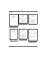
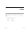
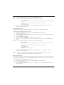
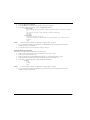
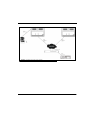
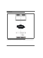
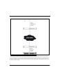
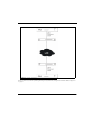
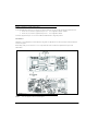
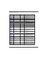
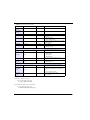
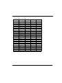
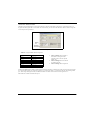
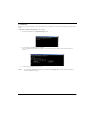
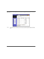
RVON-I/O User Manual
9350-7772-000 Rev P
2/2010
PROPRIETARY NOTICE
SHIPPING TO THE MANUFACTURER
The product information and design disclosed herein were originated by
and are the property of Bosch Security Systems, Inc. Bosch reserves all
patent, proprietary design, manufacturing, reproduction, use and sales
rights thereto, and to any article disclosed therein, except to the extent
rights are expressly granted to others.
All shipments of product should be made via UPS Ground, prepaid (you
may request from Factory Service a different shipment method). Any
shipment upgrades will be paid by the customer. The equipment should
be shipped in the original packing carton. If the original carton is not
available, use any suitable container that is rigid and of adequate size. If
a substitute container is used, the equipment should be wrapped in paper
and surrounded with at least four (4) inches of excelsior or similar
shock-absorbing material. All shipments must be sent to the following
address and must include the Proof of Purchase for warranty repair.
Upon completion of any repair the equipment will be returned via United
Parcel Service or specified shipper, collect.
COPYRIGHT NOTICE
Copyright 2010 by Bosch Security Systems, Inc. All rights reserved.
Reproduction, in whole or in part, without prior written permission from
Bosch is prohibited.
WARRANTY NOTICE
See the enclosed warranty card for further details.
CUSTOMER SUPPORT
Factory Service Department
Bosch Security Systems, Inc.
8601 East Cornhusker Hwy.
Lincoln, NE 68507 U.S.A.
Attn: Service
Technical questions should be directed to:
Customer Service Department
Bosch Security Systems, Inc.
12000 Portland Avenue South
Burnsville, MN 55337 USA
Telephone: 877-863-4169
Fax: 800-323-0498
[email protected]
Technical Questions EMEA
Bosch Security Systems Technical Support EMEA
http://www.rtsintercoms.com/contact_main.php
THE LIGHTNING
FLASH AND
ARROWHEAD
WITHIN THE
TRIANGLE IS A
WARNING SIGN
ALERTING YOU OF
“DANGEROUS
VOLTAGE” INSIDE
THE PRODUCT.
CAUTION: TO REDUCE THE
RISK OF ELECTRIC SHOCK,
DO NOT REMOVE COVER.
NO USER-SERVICABLE
PARTS INSIDE. REFER
SERVICING TO QUALIFIED
SERVICE PERSONNEL.
THE
EXCLAMATION
POINT WITHIN
THE TRIANGLE IS
A WARNING SIGN
ALERTING YOU
OF IMPORTANT
INSTRUCTIONS
ACCOMPANYING
THE PRODUCT
RETURN SHIPPING INSTRUCTIONS
SEE MARKING ON BOTTOM/BACK OF PRODUCT
Customer Service Department
Bosch Security Systems, Inc. (Lincoln, NE)
Telephone: 402-467-5321
Fax: 402-467-3279
Factory Service: 800-553-5992
WARNING: APPARATUS SHALL NOT BE EXPOSED TO DRIPPING OR
SPLASHING AND NO OBJECTS FILLED WITH LIQUIDS, SUCH AS VASES,
SHALL BE PLACED ON THE APPARATUS.
Please include a note in the box which supplies the company name,
address, phone number, a person to contact regarding the repair, the type
and quantity of equipment, a description of the problem and the serial
number(s).
WARNING: THE MAIN POWER PLUG MUST REMAIN READILY OPERABLE
CAUTION: TO REDUCE THE RISK OF ELECTRIC SHOCK, GROUNDING OF
THE CENTER PIN OF THIS PLUG MUST BE MAINTAINED.
WARNING: TO REDUCE THE RISK OF FIRE OR ELECTRIC SHOCK, DO NOT
EXPOSE THIS APPRATUS TO RAIN OR MOISTURE.
WARNING: TO PREVENT INJURY, THIS APPARATUS MUST BE SECURELY
ATTACHED TO THE FLOOR/WALL/RACK IN ACCORDANCE WITH THE
INSTALLATION INSTRUCTIONS.
This product is AC only.
Important Safety Instructions
1. Read these instructions.
2. Keep these instructions.
3. Heed all warnings.
4. Follow all instructions.
5. Do not use this apparatus near water.
6. Clean only with dry cloth.
7. Do not block any ventilation openings. Install in accordance with the
manufacturer’s instructions.
8. Do not install near any heat sources such as radiators, heat registers, stoves, or
other apparatus (including amplifiers) that produce heat.
9. Do not defeat the safety purpose of the polarized or grounding-type plug. A
polarized plug has two blades with one wider than the other. A grounding type
plug has two blades and a third grounding prong. The wide blade or the third
prong are provided for your safety. If the provided plug does not fit into your
outlet, consult an electrician for replacement of the obsolete outlet.
10.Protect the power cord from being walked on or pinched particularly at plugs,
convenience receptacles, and the point where they exit from the apparatus.
11.Only use attachments/accessories specified by the manufacturer.
12.Use only with the cart, stand, tripod, bracket, or table specified by the
manufacturer, or sold with the apparatus. When a cart is used, use caution when
moving the cart/apparatus combination to avoid injury from tip-over.
13.Unplug this apparatus during lightning storms or when unused for long periods
of time.
14.Refer all servicing to qualified service personnel. Servicing is required when the
apparatus has been damaged in any way, such as power-supply cord or plug is
damaged, liquid has been spilled or objects have fallen into the apparatus, the
apparatus has been exposed to rain or moisture, does not operate normally, or
has been dropped.
Table
of
Contents
INTRODUCTION ............................................. 1
SET PANEL ................................................................. 32
Description .............................................................1
Features ..................................................................1
Reference View .......................................................2
BASIC NETWORK CONFIGURATION .......35
LED EXPLANATION OF THE LED DEVICE STATUS MODULE ..2
Specifications ..........................................................3
Default Ethernet IP Addresses ...............................3
Pin Outs for Connections .......................................4
Connection Diagrams ............................................5
DIP Switches ..........................................................6
INSTALLATION ............................................... 7
System Requirements ..............................................7
Reset the Current IP Address to the
Default RVON-I/O IP Address ...............................8
Basic Installations ..................................................8
BASIC LOCAL MODE SETUP ..........................................8
BASIC REMOTE MODE SETUP .......................................9
RVON-I/O TRUNK SETUP .............................................9
RVON SERIAL PASS-THROUGH SETUP ........................10
System Diagrams ..................................................12
RVON-1 Jumpers and Connections ......................16
J2 CONNECTOR ..........................................................16
CONFIGURATION ......................................... 17
Setup IP Addresses ...............................................17
CONFIGURE THE IP ADDRESS FROM A KP-32,
KP-632, OR A KP-832 ...............................................17
CONFIGURE THE IP ADDRESS FROM A KP-812 ...........18
CONFIGURE THE IP ADDRESS USING TELNET .............19
CONFIGURE THE IP ADDRESS USING
THE SERIAL DEBUG PORT ...........................................21
CONFIGURE THE RVON-I/O USING
TELNET OR A SERIAL PORT .........................................22
CONFIGURE RVON-I/O USING TELNET
AND SERIAL PORT .......................................................23
RVON-I/O Command Table .................................25
SET SERIAL .................................................................30
SET GPIO ..................................................................30
Basic Network Configuration ...............................35
LAN (LOCAL AREA NETWORK) VS. WAN
(WIDE AREA NETWORK) ............................................... 35
LOCAL AREA NETWORK ................................. 35
WIDE AREA NETWORK ................................... 36
ACCESSING THE WIDE AREA
NETWORK (WAN) ................................................... 37
NETWORK ADDRESS TRANSLATION (NAT) ........ 37
PORTS ...................................................................... 37
IP ADDRESSES ........................................................ 39
PING A COMPUTER .................................................... 40
POSSIBLE PITFALL WITH ROUTERS,
GATEWAYS, AND SWITCHES ................................ 40
RVON Configuration ............................................41
Network Terminology ...........................................43
RVON TRUNKING CONNECTIONS ............45
Notes .....................................................................53
CHAPTER 1
Introduction
Description
Coupled with the same VOIP technology used with the RVON-8, the RVON-I/O can take legacy analog audio and convert it to
digital VOIP audio. The RVON-I/O expands the boundaries of digital audio to include analog conversion. There are many
applications in which the RVON-I/O can be used, such as:
•
•
•
•
•
ADAM Matrix AIO to RVON-I/O to RVON-1, RVON-8, RVON-I/O or VOIP Virtual Keypanel.
Zeus to RVON-I/O to RVON-1, RVON-8, RVON-I/O or VOIP Virtual Keypanel.
ADAM to RVON-I/O to Zeus
Cronus to RVON-I/O to RVON-1, RVON-8, RVON-I/O or VOIP Virtual Keypanel.
McCurdy 9500 to RVON-I/O to RVON-1, RVON-8, RVON-I/O or VOIP Virtual Keypanel.
RVON-I/O is fully compatible with the following internationally recognized standards and protocols; G.711, G.729AB, G.723.
Features
8 Channels of Bidirectional Audio
Plus Keypanel Data -
The RVON-I/O supports 8 channels IN and OUT and has
configurable network bandwidth parameters that can be tailored to
individual network conditions. Supports local and remote
keypanels.
Addressing -
Eight individually addressable audio channels. The RVON-I/O
can feed simultaneously VOIP (voice over internet protocol)capable keypanels, as well as, various other matrix intercom
systems.
Ethernet Capabilities -
The RVON-I/O uses standard Ethernet protocols and is
compatible with 10 BASE-T and 100 BASE-TX Ethernet
compliant devices and networks.
1
Reference View
FIGURE 1.
RVON-I/O Reference View
LED Explanation of the LED Device Status Module
#
2
Red LED
15
GPO 7 asserted
GPI 7 asserted
Green LED
16
GPO 8 asserted
GPI 8 asserted
17
Pass-Through Serial TX
Activity
Pass-Through Serial
RX Activity
1
VOIP not connected
channel 1
VOIP connected
Channel 1*
2
VOIP not connected
channel 2
VOIP connected
Channel 2*
3
VOIP not connected
channel 3
VOIP connected
Channel 3*
20
Shell Log Message (TX)
Activity
4
VOIP not connected
channel 4
VOIP connected
Channel 4*
21
Ethernet Half Duplex
Ethernet Full
Duplex
5
VOIP not connected
channel 5
VOIP connected
Channel 5*
22
Ethernet 10 Mbps
Ethernet 100 Mbps
VOIP connected
Channel 6*
23
Ethernet Not ‘AUTO’
Ethernet Link Good
6
VOIP not connected
channel 6
24
Remote Mode
Processor Good
7
VOIP not connected
channel 7
VOIP connected
Channel 7*
8
VOIP not connected
channel 8
VOIP connected
Channel 8*
9
GPO 1 asserted
GPI 1 asserted
10
GPO 2 asserted
GPI 2 asserted
11
GPO 3 asserted
GPI 3 asserted
12
GPO 4 asserted
GPI 4 asserted
13
GPO 5 asserted
GPI 5 asserted
14
GPO 6 asserted
GPI 6 asserted
18
19
*Green LED wink periodically when a keypanel is
connected.
** If both LEDs are OFF or not lit, the channel is NOT
configured (this only applies to LEDs 23-16).
Specifications
Connections
RJ-45 Ethernet
DB-9 I/O Port (8 bidirectional audio and keypanel data; Male)
DB-25 GPI/O Connection (Female)
DB-9 Relay Port (Female)
DB-9 Serial Port
Power
90-240 VAC
Physical
1 RU (height)
19 inches (482.6 mm) wide X 8 inches (203.2 mm) deep
Digital
TABLE 1. Digital
Specifications
Codec
Bit Rate
Coding Delay
Playout Delay
Bandwidth
MOS*
G.711
64
125 μs
20-60 ms
160-224 kbps
4.3
G.729AB
8
10 ms
20-120 ms
32-112 kbps
3.95
G.723
5.3, 6.3
30 ms
60-120 ms
29-45 kbps
3.5, 3.9
*MOS (Mean Option Score or ACR (Absolute Category Rating) is a widely known voice quality measuring method. The
scale ranges from 5 (excellent) to 0 (unacceptable). The typical desirable range for VOIP transmission is from 3.5 to 4.2.
NOTE:
The playout delay and bandwidth depend on the configured amount of audio per packet. The bandwidth values
are for bidirectional audio without VAD (Voice Activity Detection) enabled.
Analog Audio Specifications
Signal Type: Fully differential (balanced)
Nominal Level: 8dBu
Maximum Level: 20dBu
Input Impedance: High (22K Ω)
Output Impendance: Low (600 Ω)
A/D and D/A Specifications
Sampling Rate: 8 KHz
Resolution: 8 bits
Converter Architecture: 128x Over-sampling Σ - Δ Modulator
Default Ethernet IP Addresses
TABLE 2. Default
Address for the RVON Product Line
Product
RVON-I/O
RVON-8
RVON-1
RVON-C
RVON-16
GPIO-16
MCII-e
Cronus
Zeus III
Default IP Address
192.168.0.1
192.168.0.2
192.168.0.3
192.168.0.4
192.168.0.5
192.168.0.6
192.168.0.7
192.168.0.8
192.168.0.9
Default Subnet Mask
255.255.0.0
255.255.0.0
255.255.0.0
255.255.0.0
255.255.0.0
255.255.0.0
255.255.0.0
255.255.0.0
255.255.0.0
3
Pin Outs for Connections
RJ-45
Pin
Function Ethernet
DB-9
Pin
3
+12V Through 300 Ohm Resistor
4
Closed 1
1
Ethernet TPO+
5
Open 1
2
Ethernet TPO-
6
Common 0
3
Ethernet TPI+
7
GND
4
TPO+
8
GND
5
TPO-
9
Common 1
6
Ethernet TPI-
7
TPI+
8
TPI-
DB-9
Pin
DB-25 Pin
Function I/O
1
RS485+
2
RS485-
3
N/A
4
RVON-I/O Audio IN+
5
RVON-I/O Audio IN-
6
N/A
7
RVON-I/O Audio OUT-
8
RVON-I/O Audio OUT+
9
N/A
See page Figure 2, “DB-9 Crossover Cable Connection
Diagram,” on page 5.
Function GPI/O
1
GPO 1
2
GPO 2
3
GPO 3
4
GPO 4
5
GPO 5
6
GPO 6
7
GPO 7
8
GPO 8
9
GND
10
GND
11
GND
12
GND
13
GND
14
GPI 1
15
GPI 2
DB-9
Function Serial Port
16
GPI 3
1
N/A
17
GPI 4
2
RXD, RVON-I/O Received Data (RS485-)
18
GPI 5
TXD, RVON-I/O Transmitted Data
(RS485+)
19
GPI 6
3
20
GPI 7
4
N/A
21
GPI 8
5
GND
22
GND
6
N/A
23
GND
7
N/A
24
GND
8
N/A
25
GND
9
N/A
NOTE:
DB-9
Pin
4
Function Relay 1&2
Function Relay 1&2
1
Closed 0
2
Open 0
The DB-25 pin GPI/O connector can be
directly connected to the Zeus, Zeus II, ADAM
CS, and ADAM
** Connection to a Cronus Intercom requires a customer
cable assembly.
Connection
Diagrams
RJ-21 To DB-9
Connection Diagram
FIGURE 4.
RJ-45 to DB-9
Crossover Connection Diagram
FIGURE 6.
DB-9 Crossover Cable
Connection Diagram
FIGURE 2.
RJ-12 to DB-9
Crossover Cable Connection
Diagram
FIGURE 3.
RJ-45 to DB-9
Connection Diagram
FIGURE 5.
Straight DB-9 to DB-9
Connection Diagram
FIGURE 7.
5
DIP Switches
DIP Switch 1:
RVON-I/O Mode
Default Position:
Open
Switch Position:
Open - Local Mode
Closed - Remote Mode
Description:
There are two (2) modes in which the RVON-I/O can run: local and remote mode
In Local mode, keypanels are directly connected to the RVON-I/O. For example, a KP-32 is
connected serially to the RVON-I/O which is connected via Ethernet to the RVON-8 in the
ADAM system. The connection between the KP-32 and the RVON-I/O is local.
In Remote mode, a digital keypanel (such as a KP-32 with RVON-1) is connected to an
RVON-I/O, which is then connected to an ADAM CS, Zeus, Cronus or an ADAM with AIO
cards.
NOTE:
DIP Switch 2:
Serial Debug Shell
Default Position:
Open
Switch Position:
Open - Pass-through port enabled
Closed - Serial Debug Shell enabled; IP configuration on Audio Port 8.
Description
When the Dip Switch is closed, serial debug is enabled. When the Dip switch is open, the
pass-through port is enabled.
The Pass-through Port is used to send serial port data over Ethernet.
The Serial Debug Shell provides the user access to a command shell (this is similar to Telnet,
except the connection is made through a serial cable).
The IP configuration on I/O Port 8 allows users to connect and configure the IP Address of the
RVON-I/O using a compatible keypanel (KP-32, KP-632, KP-832, and KP-812) connected
serially to I/O Port 8 on the back of the RVON-I/O. IP Configurations are made from the
keypanel service menu. Note, you must have keypanel firmware version 2.02 or higher to
configure the IP Address.
DIP Switch 3:
Telnet Shell
Default Position:
OPEN
Switch Position:
OPEN - Telnet Shell is enabled
CLOSED - Disabled, user name and password are set to default
Description
Using telnet, you can set permissions and configurations within the RVON-I/O application. See
Table , “RVON-I/O Command Table,” on page 25.
DIP Switch 4:
Boot Downloader
Default Position:
Open
Switch Position:
Open - Boot downloader is disabled (runs the native flash program)
Closed - Boot downloader is enabled (runs the boot downloader)
Description:
6
To see system drawing scenarios of both local and remote mode, see “System
Diagrams” on page 12
Switches to the boot downloader flash program. This program is sent with the RVON-I/O in case
the native flash program becomes corrupt.
CHAPTER 2
Installation
The RVON-I/O can operate in one of two modes, LOCAL mode or REMOTE mode. When operating in LOCAL mode,
keypanels are directly connected to the RVON-I/O. For example, a KP-32 is connected serially to the RVON-I/O, which is
connected via Ethernet to the RVON-8. The KP-32 RVON-I/O is in LOCAL mode. When operating in REMOTE mode, a
digital keypanel (such as KP-32 with RVON-1) is connected via Ethernet to an RVON-I/O, which is then connected to an
intercom.
System Requirements
Before you install the RVON-I/O, verify the following items are updated:
Product
Firmware
RVON-I/O
RVON-1
RVON-8
Master Controller
KP-32
AZedit
VKP
1.0.0 or higher
1.1.0 or higher
1.2.0 or higher
9.22.0 or higher
2.0.2 or higher
2.08.0 or higher
1.0.1 or higher
7
Reset the Current IP Address to the Default RVON-I/O IP Address
The RVON-I/O is shipped with a default IP Address already configured on the unit. The default IP Address is 192.168.0.1,
the default Netmask is 255.255.0.0, the default Gateway is set to zero. This feature is useful when using an RVON-I/O in the
field (i.e.; a mobile truck) where the IP Address is constantly changing from on destination network to the next. By being able
to reset the IP Address to a default address, you will be able to connect to the RVON-I/O without having to remember the IP
Address of the previous location. For more information on configuring the IP Address, see “Reset the Current IP Address to
the Default RVON-I/O IP Address” on page 8.
To reset the IP Address to default on the RVON-I/O, do the following:
1.
On the front of the RVON-I/O unit, push and hold buttons 1 and 2, then push the RESET button.
Hold the buttons in for 15 seconds or until all the LED lights blink rapidly. When all the LED lights blink rapidly, the
RVON-I/O IP Address has been reset to the default.
NOTE: If buttons 1 and 2 are pressed during power ON, the unit will reset the IP Address.
Basic Installations
On the following pages, installation for Basic Local Mode, Basic Remote Mode, and Basic Trunked systems will be explained.
NOTE:
When using Zeus with RVON-I/O GPI/O you must uncheck the “Configure onboard GPI/Os in FR9528 mode”
BEFORE you configure your system. If you set this after you configure your panels, it will cause the Zeus
configuration to be reset.
Basic Local Mode Setup
NOTE:
Keypanel version is not relevant in Local Mode.
In LOCAL mode, the keypanel is directly connected to the RVON-I/O through the use of a DB-9 serial cable.
To setup an RVON-IO local mode system, do the following
8
1.
On the back of the RVON-I/O, put DIP switch 1 in the OPEN position (LOCAL mode).
2.
Power ON the RVON-I/O unit.
3.
Connect keypanels to the RVON-I/O (I/O ports), using a straight DB-9 (serial cable). See page 5
4.
Connect the RVON-I/O to the Ethernet.
5.
Set the IP Address for the RVON-I/O.
6.
NOTE:
Using Telnet or Serial programming (see ), configure the RVON-I/O as follows:
To see actual Telnet commands, see “RVON-I/O Command Table” on page 25.
set channel [chan]
dest ip_addr (IP Address of the RVON-1, RVON-8, or RVON-I/O that is connected to the RVON-I/
O)
dest_type (the type of device, either an RVON-1, RVON-8, or RVON-I/O)
dest_chan
dest_codec (optional)
7.
Once you are finished configuring the RVON-I/O, type ACTIVATE into the command prompt to activate the
configuration setup on the RVON-I/O
Basic Remote Mode Setup
In Remote Mode, the keypanel with RVON-1 installed is directly connected to the RVON-I/O via Ethernet.
To setup a basic remote mode system, do the following:
1.
On the back of the RVON-I/O, put DIP switch 1 in the CLOSED position (Remote Mode).
2.
Power ON the RVON-I/O unit.
3.
Connect the matrix system to the RVON-I/O (I/O ports), using a DB-9 crossover cable. See page 5 for the different
connection diagrams.
4.
Connect the RVON-I/O to Ethernet.
5.
Set the IP Address for the RVON-I/O (see “Setup IP Addresses” on page 17).
6.
Using Telnet or Serial programming (see “RVON-I/O Command Table” on page 25), configure the RVON-I/O as
follows.
NOTE:
To see actual Telnet commands, see “RVON-I/O Command Table” on page 25.
set channel [chan]
dest ip_addr (IP Address of the RVON-1, RVON-8, or RVON-I/O that is connected to the RVON-I/
O)
dest_type (the type of device, either an RVON-1, RVON-8, or RVON-I/O)
dest_chan
dest_codec (optional)
set panel [panel]
poll_id (see “Set Panel” on page 32)
baud
7.
NOTE:
Once you are finished configuring the RVON-I/O, type ACTIVATE into the command prompt to activate the
configuration setup on the RVON-I/O.
If you do not have a RVON-1 pre-installed, the KP-32 or the KP-812 must have the RVON-1 component
installed prior to Remote setup (See the RVON-1 User Manual for details).
RVON-I/O Trunk Setup
When trunking two intercom systems over Ethernet using RVON-I/O, you can setup the RVON-I/O on both ends of the trunks
in either LOCAL or REMOTE mode. However, a REMOTE to REMOTE mode system is the preferred way of trunking.
To setup remote mode in a trunked system, do the following:
1.
On the back of the RVON-I/O, put DIP switch 1 in the CLOSED position (Remote Mode).
2.
Power ON the RVON-I/O unit.
3.
Connect the Matrix to the RVON-I/O (via I/O ports), using a DB-9 crossover cable. See page 5 for the different
connection diagrams.
9
4.
Connect the RVON-I/O to Ethernet.
5.
Set the IP Address for the RVON-I/O (see “Setup IP Addresses” on page 17).
6.
Using Telnet or Serial programming, configure the RVON-I/O as follows:
set channel [chan]
dest ip_addr (IP Address of the RVON-1, RVON-8, or RVON-I/O that is connected to the RVON-I/
O)
dest_type (the type of device, either an RVON-1, RVON-8, or RVON-I/O)
dest_chan
dest_codec
set panel [panel]
poll_id (see “Set Panel” on page 32)
NOTE: If the RVON-I/O is in Remote Mode, set the Panel Poll ID to 0, so it will not be seen as
keypanel.
baud
NOTE:
To see actual Telnet commands, see “RVON-I/O Command Table” on page 25.
7.
Once you are finished configuring the RVON-I/O, type ACTIVATE into the command prompt to activate the
configuration setup on the RVON-I/O
8.
To set up the other side of the trunk system, repeat steps 1 through 7.
RVON Serial Pass-through Setup
The Serial Pass through is the path in which data is sent and received.
1.
Verify the correct port is selected - on J1 see “Pin Outs for Connections” on page 4.
2.
Verify the serial connections are correct.
3.
Verify Pass Through Port is enabled (DIP Switch 2 OPEN), see “Connection Diagrams” on page 5.
4.
Verify the RVON-I/O baud rate matches the baud rate of the device it is connecting with.
5.
Using Telnet or Serial programming, configure the RVON-I/O as follows:
set serial
mode
ip_addr
baud
NOTE:
6.
10
To see actual Telnet commands, see “RVON-I/O Command Table” on page 25.
Once you are finished configuring the RVON-I/O, type ACTIVATE into the command prompt to activate the
configuration setup on the RVON-I/O.
FIGURE 8.
Serial Pass-Through system diagram
11
System Diagrams
FIGURE 9.
Local Mode
This system diagram shows Local mode. It is called local mode because the keypanel is connected directly to the RVON-I/O
on the opposite side of the network from the Matrix. The keypanels act as though they are locally connected to the matrix.
12
FIGURE 10.
Remote Mode
Remote Mode means the keypanels are not connected to the RVON-I/O directly. In the example, the KP-32 with RVON-1 or
the VKP has to pass through the LAN/WAN before connecting to the RVON-I/O. In Remote Mode, the RVON-I/O is on the
Matrix side of the network and the keypanels are on the other side of the network.
13
FIGURE 11.
Local and Remote Mode
The lower portion of Figure 11 shows a local setup (the keypanel is directly connected to the RVON-I/O), while the upper
portion of the graphic shows a remote setup. The RVON-I/O works similar to an audio converter box. In the lower portion of
the graphic, the audio coming from the KP-32 going towards the RVON-I/O changes from analog to digital audio (and vice
versa). The same holds true for the upper portion of the graphic, where the audio coming from the RVON-I/O going towards
the Zeus is converted to analog.
14
FIGURE 12.
Trunking with RVON-I/O
When you trunk two (2) intercom systems together using two (2) RVON-I/O’s, configure both in Remote Mode (see Figure 10
on page 13.
15
RVON-1 Jumpers and Connections
A selectable RS232/485 serial port is a connector J1. Jumper connections on J10, J11, and J12 select the signal mode on J1.
•
•
When J10, J11, and J12 are jumped from pins 1 to 2 - J1 is configured for RS485. (Default)
When J10, J11, and J12 are jumped from pins 2 to 3 - J1 is configured for RS232.
J21 must be jumped from pins 1 to 2 to select UART B for RS485 RVON-1 keypanel operation.
J2 Connector
The RVON-1 card is designed to be used with either a keypanel or an RVON-I/O card. The J2 connector mounts the RVON-1
card onto a keypanel.
RS232 debug serial port via Connector J3. J3 is a 6-pin heater that connects to RS-232 compatible serial ports of the
TNETV2020.
FIGURE 13.
NOTE:
16
Front and back of the RVON-1 board
Pin 1 of a jumper is shown as a black square.
CHAPTER 3
Configuration
Setup IP Addresses
There are three ways in which the IP Address can be set on the RVON-I/O; via a keypanel, through Telnet, or using the Serial
Debug Port.
If you are using a keypanel to set the IP Address of the RVON-I/O, you must use a KP-32, KP-632, KP-832, or a KP-812.
There are two sets of instructions to configure the IP Address from a KP-32, KP-632, KP-832 and a KP-812. This is because
the KP-812 uses encoder knobs to navigate its menu system. For instructions on how to use the KP-812 to configure the IP
Address, see “Configure the IP Address from a KP-812” on page 18.
Configure the IP Address from a KP-32, KP-632, or a KP-832
NOTE:
Make sure DIP switch 1 is in the OPEN position (LOCAL mode - LED 24 RED is NOT lit). Also, make sure DIP
switch 2 is in the CLOSED position (configuration via IO port 8 enabled).
To configure the IP Address from a KP-32, KP-632, KP-832 keypanel, do the following:
1.
NOTE:
Connect the RVON-I/O using serial cable from the IO port 8 on the unit to the FRAME connector on the KP-32, KP632, or KP-832.
The firmware on the KP-32, KP-632, KP-832 keypanels needs to be at version 2.0.2 or higher.
2.
On the KP-32, KP-632, and KP-832, press Menu.
The Display menu item appears.
3.
Press the up arrows or down arrows to scroll to Service.
4.
Press PGM.
The Aux Inputs menu item appears.
5.
Press the up arrows or down arrows to scroll to RVON Setup.
6.
Press PGM.
The IP Address menu item appears.
7.
Press PGM.
The current IP Address appears.
8.
Enter the first number in the IP Address.
This activates the first octet of the IP Address and clears the rest of the IP Address.
9.
Press PGM.
This confirms the first octet in the IP Address and moves you to the second octet.
17
NOTE:
Press PGM to skip over any octet that does not need modification.
10.
Repeat steps 8 and 9 until the entire IP Address is entered.
11.
Press PGM.
The Netmask menu item appears.
NOTE:
Once you have entered the IP Address, you will then enter the Netmask. The Netmask is a string of numbers
similar to an IP Address, except that it masks or screens out the network port of an IP Address so that only the
host computer part of the address remains (for example, 255.255.255.0).
12.
Press PGM.
The current Netmask appears.
13.
Enter the first number in the Netmask.
This activates the first octet in the Netmask and clears the rest of the Netmask.
14.
Press PGM.
This confirms the first octet in the Netmask and moves you to the second octet.
NOTE:
Press PGM to skip over any octet that does not need modification.
15.
Repeat steps 13 and 14 until the entire Netmask is entered.
16.
Press PGM.
The Gateway IP Address menu item appears.
NOTE:
Once you have entered the Netmask, you may need to enter the Gateway IP Address. A Gateway is a node (for
example, a computer) on a network that serves as an entrance to another network.
17.
Press PGM.
The current Gateway IP Address appears.
18.
Enter the first number in the Gateway IP Address.
This activates the first octet of the Gateway IP Address and clears the rest of the address.
19.
Press PGM.
This confirms the first octet in the Gateway IP Address and moves you to the second octet.
NOTE:
Press PGM to skip over any octet that does not need modification.
20.
Repeat steps 18 and 19 until the entire Gateway in entered.
21.
Press PGM.
22.
Press CLR to exit the menu.
The changes are now enabled.
Configure the IP Address from a KP-812
To configure the IP Address from a KP-812 keypanel, do the following:
NOTE:
18
The firmware must be at 1.1.1 or higher.
1.
On the KP-812 turn the Select knob to scroll to Menu.
2.
Tap the Select knob.
The top level menu appears.
3.
Turn the Select knob to scroll to the Service menu item.
4.
Tap the Select knob.
The Service menu appears.
5.
Turn the Select knob to scroll to the RVON Setup menu item.
6.
Tap the Select knob.
The IP Address menu item appears.
7.
Tap the Select knob.
The current IP Address appears.
8.
Enter the first number in the IP Address.
This activates the first octet of the IP Address and clears the rest of the IP Address.
9.
Tap the Select knob.
This confirms the first octet in the IP Address and moves you to the second octet.
NOTE:
Tap the Select knob to skip over any octet that does not need modification.
10.
Repeat steps 8 and 9 until the entire IP Address is entered.
11.
Tap the Select knob.
The Netmask menu item appears.
NOTE:
Once you have entered the IP Address, you will then enter the Netmask. The Netmask is a string of numbers
similar to an IP Address, except that it masks or screens out the network part of an IP Address so that only the
host computer part of the address remains (for example, 255.255.255.0).
12.
Tap the Select knob.
The current Netmask appears.
13.
Enter the first number in the Netmask.
This activates the first octet in the Netmask and clears the rest of the Netmask.
14.
Tap the Select knob.
This confirms the first octet in the Netmask and move you to the second octet.
NOTE:
Tap the Select knob to skip over any octet that does not need modifications.
15.
Repeat steps 13 and 14 until the entire Netmask is entered.
16.
Tap the Select knob.
The Gateway IP Address menu item appears.
NOTE:
Once you have entered the Netmask, you may need to enter the Gateway IP Address. A Gateway is a node (for
example, a computer) on a network that serves as an entrance to another network.
17.
Tap the Select knob.
The current Gateway IP Address appears.
18.
Enter the first number in the Gateway IP Address.
This activates the first octet of the Gateway IP Address and clears the rest of the address.
19.
Tap the Select knob.
This confirms the first octet in the Gateway IP Address and moves you to the second octet.
NOTE:
Tap the Select knob to skip over any octet that does not need modifications.
20.
Repeat steps 18 and 19 until the entire Gateway is entered.
21.
Tap the Select knob.
22.
Press and hold the Select knob to exit the menu.
The changes are now enabled.
Configure the IP Address Using Telnet
NOTE:
In order to use Telnet to set a new IP Address for you RVON-I/O, you must know the existing IP Address. If you
do not know the existing IP Address, you can reset the IP Address. See “Configure the IP Address Using Telnet”
on page 19. Also, you must make sure Telnet is enabled (DIP Switch 3 OPEN).
The following instructions will show you how to access the Telnet screens and show you some of the information you can
display and edit.
19
To display settings for the RVON-I/O, do the following:
1.
Open a Command Prompt application session.
2.
At the prompt type TELNET <IP Address> (The IP Address is the existing IP Address assigned to the RVON-I/O).
Figure 3.
3.
Press Enter.
The RVON login screen appears.
4.
In the logon field, type the RVON login (default = telex).
5.
Press Enter.
6.
In the password field, type the RVON password (default = password).
7.
Press Enter.
An arrow prompt appears.
Figure 4.
20
8.
At the prompt, type dbgcmd to access the debug command screens.
Figure 5.
9.
Press Enter.
An MXP prompt appears.
10.
At the MXP prompt, type set rvon ip_addr 10.3.210.12 (this IP Address is for example purposes only).
11.
Press Enter.
The IP Address is set for the RVON-I/O.
12.
Set the Netmask.
13.
At the MXP prompt, type Activate.
RVON-I/O will reset itself to the new IP Address. The current telnet session becomes invalid.
Configure the IP Address Using the Serial Debug Port
NOTE:
In order to use the Serial Debug Port to set the IP Address for your RVON-I/O, you must know the intended IP
Address. Also, you must make sure DIP switch 2 is not enabled (CLOSED).
The following instructions will show you how to access the Serial Debug Port screens and show you how to configure the IP
Address for the RVON-I/O
To configure the IP Address for the RVON-I/O, do the following:
1.
Connect the PC’s COM port to the RVON-I/O’s serial connector.
2.
Run a HyperTerminal program.
The window provided Hyper Terminal is located at Start Programs>Accessories>Communications >HyperTerminal.
3.
At the prompt, type dbgcmd.
21
4.
At the MXP prompt, set rvon ip_addr 10.3.210.20 (this IP Address is for example purposes only).
Figure 6.
5.
Press Enter.
An MXP prompt appears.
6.
Press Enter.
The IP Address is set for the RVON-I/O.
7.
Set the Netmask.
8.
At the MXP prompt, type Activate.
RVON-I/O will reset itself to the new IP Address. The current telnet session becomes invalid.
Configure the RVON-I/O Using Telnet or a Serial Port
RVON-I/O programming can be done using a direct serial connect to or a Telnet connection. There are two physical
connections to an RVON-I/O:
Direct serial through a custom serial cable (connected on the back of the RVON-I/O at SERIAL)
Ethernet (Telnet Only)
Setup
Serial Port: 38,4000 baud, 8 data bits, 1 stop bit, No Parity, NO-Flow control
Telnet: IP Address, port 23
22
Configure RVON-I/O Using Telnet and Serial Port
IMPORTANT:
Because the RVON-I/O is shipped with a default IP Address it may not be accessible on the network.
The IP Address should already be configured before attempting to try to connect through Telnet. To set
the IP Address, see “Setup IP Addresses” on page 17.
If the RVON-I/O already has an IP Address compatible with your network, you can configure the RVON-I/O thr4ough the use
of Telnet. The following instructions will show you how to access the Telnet screens and show you some of the information
you can display and edit.
To display the settings for an RVON-I/O, do the following:
1.
Open a command prompt.
2.
At the prompt, type TELNET <IP Address> (The IP Address is the IP Address assigned to the RVON-I/O).
Figure 7. Telnet
3.
IP Address
Press Enter.
The RVON login screen appears.
Figure 8. Telnet
Password
4.
In the login field, type the RVON login (default = telex).
5.
Press Enter.
6.
In the password field, type the RVON password (default = password).
7.
Press Enter.
A prompt appears.
23
8.
At the prompt, type dbgcmd to access the debug command screens.
Figure 9. Telnet
9.
24
Press Enter.
An MXP prompt appears.
Debug Command screen
RVON-I/O Command Table
TABLE 10. RVON-I/O
Command
Command Table
Parameter 1
Parameter 2
Description
show rvon
Shows RVON-I/O IP Address and other
general information.
show channel
Shows destination address and connection
information.
show serial
Shows serial port setting.
show gpio
Shows gpio settings.
show panel
Shows the channel control settings (poll id
and baud rate).
show emac
Shows Ethernet settings.
set rvon
Help screen which lists all “set rvon”
commands.
set rvon
ip_addr
X.X.X.X
Set the IP Address for the RVON-I/O.
set rvon
net mask
X.X.X.X
Set the Network Mask for the RVON-I/O.
set rvon
gateway
X.X.X.X
Set the Gateway IP Address for the RVON-I/
O.
set rvon
user
username
Set the RVON-I/O user name for Telnet
access.
Default = telex
set rvon
password
password
Set the RVON-I/O password for Telnet
access (8-40 characters).
Default = password
set rvon
vad_threshold
adaptive (#)
Set the VAD threshold (silence detection).
Adaptive refers to autoselect. The # can be 20 to +10 dBm.
Help screen, which lists all “set chan”
commands (0-7). This refers to VOIP
channel setting.
set channel
[chan]
set channel
[chan]
dest_ip
X.X.X.X
Set the destination IP Address for this
particular RVON channel.
set channel
[chan]
dest_type
X
X = 0 (rvon-8), 1 (rvon-1, 2 (rvon-I/O
set channel
[chan]
dest_chan
X
Set the destination channel - the port on the
far end (0-7).
set channel
[chan]
chan_codec
X
Set the profile to use which includes the
compression codec (0-27) (see Table 10 on
page 25).
set channel
[chan]
input_gain
X
Set the input gain for the specified channel 14 to +14dB
set channel
[chan]
output_gain
X
Set the output gain for the specified channel 14 to +14 dB.
25
TABLE 10. RVON-I/O
Command
Command Table
Parameter 1
Parameter 2
set channel
[chan]
onhook
force the channel to disconnect.
set channel
[chan]
offhook
force the channel to connect.
Help screen, which lists all “set serial”
commands.
set serial
set serial
mode
X
Set the serial mode.
0 = Pass Through mode
set serial
ip_addr
X.X.X.X
Set the destination IP Address for this serial
pass-through port.
set serial
ip_addr_2
X.X.X.X
Not Available
set serial
baud
X
Set the baud rate to use:
50 through 115000.
set gpio
Help screen, which lists all “set gpio”
commands.
set gpio
mode
X
Set the gpio mode.
0 = Pass Through
1 = 1 Keypanel
2 = All Keypanels
set gpio
ip_addr
X.X.X.X
Set the destination IP Address for passthrough mode.
set gpio
panel
X
Set the IO port the gpio are associated with
on the RVON-I/O.
set panel
Help screen, which lists all “set panel”
commands.
set panel
[pnl]
poll_id
X
Make sure the panel poll_id corresponds to
the source of the audio it is connected to.
0-10
0= do not respond to polls
set panel
[pnl]
baud
X
Set the baud rate for the panel.
9600 or 76800
Examples:
Set RVON ip_addr to 10.3.210.12.
> At the command prompt, type
set rvon ip_addr 10.3.210.12
Set the destination channel type to RVON-I/O.
> At the command prompt, type:
set channel [chan_dest num_type 2
26
Description
Set the RVON login user name to Keypanel
> At the command prompt, type:
set rvon user Keypanel
NOTE:
For more information on Set Serial, Set GPIO, and Set Panel see, “Set Serial” , “Set GPIO” and “Set Panel” on
page 32.
27
Bandwidth (kbps/channel)
Bandwidth (kbps/side)
Bandwidth (Bytes/sec)
Total Packet Size (bytes)
IP Overhead (bytes)
Encoded Audio (bytes)
Packets/Second
0,3,6,9
G.711
64k
10
100.00 80
60
140
14000
112
224
1,4,7,10
G.711
64k
20
50.00
160
60
220
11000
88
176
2,5,8,11
G.711
64k
30
33.33
240
60
300
10000
80
160
12,16
G.729
8k
10
100.00 10
60
70
7000
56
112
13,17
G.729
8k
20
50.00
20
60
80
4000
32
64
14,18
G.729
8k
40
25.00
40
60
100
2500
20
40
15,19
G.729
8k
60
16.67
60
60
120
2000
16
32
20,22
G.723
5.3k
30
33.33
24
60
84
2800
22.4
44.8
24,26
G.723
6.3k
30
33.33
24
60
84
2800
22.4
44.8
21,23
G.723
5.3k
60
16.67
48
60
108
1800
14.4
28.8
25,27
G.723
6.3k
60
16.67
48
60
108
1800
14.4
28.8
Codec Rate
Codec
Audio (ms) / Packet
Specifications.
Coding Profile
TABLE 11. Codec
NOTE:
A channel consists of a transmitting and a receiving side, so the bandwidth is double for a bidirectional audio stream.
NOTE:
Bandwidth values are approximate maximums, actual bandwidth could be considerably lower with
VAD enabled.
Codec:Determines how the audio is compressed/decompressed and the name given to the defined algorithm.
Codec Rate:Actual bits per second of the audio in compressed form. This is sent over the network through various data
packets. Network efficiency can be calculated with an IP header for each packet of X ms of audio.
Size:Amount of audio in each IP Packet, milliseconds (ms)
VAD:Voice Activity Detection, when enabled and only when audio is above a certain threshold, will send packets. Otherwise,
a silence packet is sent once, and not again until audio is above the threshold. Enabling this will result in a more efficient
network, but care must be taken to because of the mother’s day phenomenon. If there is ever a need to have all audio paths
open and active, a network designer must account for this scenario.
28
TABLE 12. Supplemental
Coding
Coding Table
Codec
Codec Rate
Size
VAD
0
711u
64k
10
Y
1
711u
64k
20
Y
2
711u
64k
30
Y
3
711u
64k
10
N
4
711u
64k
20
N
5
711u
64k
30
N
6
711A
64k
10
Y
7
711A
64k
20
Y
8
711A
64k
30
Y
9
711A
64k
10
N
10
711A
64k
20
N
11
711A
64k
30
N
12
729AB
8k
10
Y
13
729AB
8k
20
Y
14
729AB
8k
40
Y
15
729AB
8k
60
Y
16
729AB
8k
10
N
17
729AB
8k
20
N
18
729AB
8k
40
N
19
729AB
8k
60
N
20
723
5.3k
30
Y
21
723
5.3k
60
Y
22
723
5.3k
30
N
23
723
5.3k
60
N
24
723
6.3k
30
Y
25
723
6.3k
60
Y
26
723
6.3k
30
N
27
723
6.3k
60
N
29
Default Setup
Every attempt is made to ensure the board is shipped from the factory containing the following settings.
All are “set rvon” commands
COMMAN
D
DEFAULT VALUE
ip_addr
192.168.0.1
IP address for the RVON-I/O
netmask
255.255.0.0
Network mask for the RVON-I/O
gateway
none
Gateway IP address for the RVON-I/O
user
telex
RVON-I/O username for Telnet access.
password
password
RVON-I/O password for Telnet access (8-40
characters).
vad_thresho
ld
10
VAD Threshold
DESCRIPTION
There are more parameters the software will auto-configure if they have not been previously setup.
All are “set channel #” commands because they are for each audio channel.
COMMAN
D
DEFAULT VALUE
dest_ip
0.0.0.0
Destination IP Address for this particular
channel.
dest_type
0
Destination type X = 0 (rvon-8), 1 (rvon-1), 2
(rvon-I/O)
dest_chan
0
Destination channel - the port on the far end (07)
chan_codec
0
Profile to use (previous coding table).
DESCRIPTION
Set Serial
When using Serial Pass-Through Mode, you must set the serial port you will use with the IP Address for the destination serial
pass-through port you are going to use. You must also set the baud rate at which data will be transmitted over the serial port
(DIP Switch 2 OPEN). For more information on DIP switches, see “Connection Diagrams” on page 5.
Set GPIO
When configuring the GPI/O on the RVON-I/O, there are three different mode options you may choose:
Pass-Through Mode for GPI/O:In Pass-Through mode, GPI/O status is sent over Ethernet, therefore you must set the IP
Address of the destination GPI/O pass-through port.
1 Keypanel (Single Port) Mode:In 1 Keypanel mode, also referred to as single port mode, all GPI/O on the RVON-I/O are
associated with only one keypanel. Associating the GPI/O with a keypanel allows you to access/address the GPI/O in UPL
Statements. Use the Set Panel parameter to designate which RVON-I/O port is associated with all the GPI/O’s on the unit.
30
1 KEYPANEL MODE EXAMPLE
The GPI/O is associated with Port 0. This means that Port 0 will have eight GPI/O’s mapped to it. Connected to Port 0 is a
keypanel with the keypanel ID of 33 in AZedit. To use the GPI/O, you can create UPL statements. But be careful to assign the
correct Output Action parameters.
Table 13. UPL
TABLE 14. 1
Keypanel Mode GPI/O assignments
LOCAL
GPI/O
GPI/O 9
Statement Example
RVON-I/O GPI/O
HARDWARE PORT
•
GPI/O 1 through 4 are assigned as
local GPI/O’s on keypanels (for
example, a KP-32 with an optional
GPI/O card.
•
GPI/O 5 through 8 are reserved and
not used at this time.
•
GPI/O 9 through 16 are assigned as
DB-25 Port 1
GPI/O 10
DB-25 Port 2
GPI/O 11
DB-25 Port 3
GPI/O 12
DB-25 Port 4
GPI/O 13
DB-25 Port 5
GPI/O 14
DB-25 Port 6
GPI/O 15
DB-25 Port 7
GPI/O 16
DB-25 Port 8
All Keypanel (Multiple Port) Mode:In All Keypanel mode, also referred to as multiple port mode, each keypanel is associated
to its corresponding GPI/O. For example, if keypanel 1 is connected to GPI/O 1, it is associate with the corresponding GPI/O
port. When using All Keypanel mode, an additional GPI/O is available. This means that each keypanel has 4
GPI/O and then a GPI/O associated with port 9.
31
NOTE:
The extra port 9 only is currently applicable to the ADAM Intercom System setup.
TABLE 15. All
Keypanel Mode GPI/O assignments
LOCAL
GPI/O
RVON-I/O GPI/O
HARDWARE PORT
GPI/O 9
DB-25 Port 1
GPI/O 9
DB-25 Port 2
GPI/O 9
DB-25 Port 3
GPI/O 9
DB-25 Port 4
GPI/O 9
DB-25 Port 5
GPI/O 9
DB-25 Port 6
GPI/O 9
DB-25 Port 7
GPI/O 9
DB-25 Port 8
Set Panel
Set Panel sets the address at which the RVON-I/O will respond to polls sent by the Intercom. If the RVON-I/O is connecting
to a Zeus or AIO-8, you must set a Panel Poll ID. The panel poll ID is the data port address from which it communicates.
Also, the panel poll ID is only used in remote mode.
Because the Zeus and AIO-8 share their data across 8 ports, they need to differentiate ports by using addresses. Therefore, to
communicate with the right port you need to communicate with the specified address.
EXAMPLE:
2 RVON-I/O units are connected to the same Zeus System (RVON-I/O A and RVON-I/O B)
RVON-I/O A is connected to Zeus ports 1 and 2 on RVON-I/O ports 1 and 2.
RVON-I/O B is connected to Zeus ports 3 and 4 on RVON-I/O ports 1 and 2.
Because the Zeus cannot differentiate either of the RVON-I/O ports 1 and 2, it is necessary to adding an address to the ports:
RVON-I/O A
RVON-I/O B
port 1 set to 1 (set panel 0, poll ID 1)
port 2 set to 2 (set panel 1, poll ID 2)
port 1 set to 3 (set panel 0, poll ID 3)
port 2 set to 4 (set panel 1, poll ID 4)
If you are using Cronus or AIO-16 with RVON-I/0 in Remote mode for keypanels, you will still have to set a panel poll ID.
This is because the RVON-I/O has a default panel poll ID of 0 (zero). This must be changed to a non-zero number.
NOTE:
Make sure to set the panel poll ID to 0 when trunking in Remote Mode. Doing this will ensure the RVON-I/O
will not respond to polls as a keypanel.
If the RVON-I/O in local mode is directly connected to a keypanel, the panel poll ID does not have to be set. The RVON-I/O
through polling will discover the address of the keypanel.
NOTE:
If you are getting audio, but cannot see the alphas on the keypanels, verify the set panel ID is set correctly.
If you connect an RVON-I/O in Local mode to an intercom serially, you must NOT connect the data lines.
32
33
34
APPENDIX A
Basic Network Configuration
Basic Network Configuration
This section covers basic network configuration set-up and testing. Also covered are basic concepts and operations, including
the difference between LAN and WAN networks and how IP Addressing is used.
In a networked environment, such as a company, typically there are many computers connected together using a router or a
switch. In larger companies, there may be several different routers distributed in buildings and plant locations. A router allows
any LAN-side computer to communicate with other computers and devices outside the LAN (local area network). Routers
send data packets from one place to another place on a network. routers use network addresses to route packets to the correct
destination. For example, in a TCP/IP network, the IP (internet protocol) address of the network interface is used to direct
router destinations.
Because routers help computers inside the LAN “talk” with computers outside of the LAN, the security of a company’s LAN
may be compromised by gaps of open ports in the router. Security measures may have been instituted to compensate for these
vulnerabilities. Consult you network administrator to learn about the security measures taken to protect your network. VPN, or
virtual private network, is one such security measure to protect the intelligence of the LAN. A computer outside the LAN must
have an address or key known by the VPN to allow access to the LAN. Many companies use a VPN to connect two different
LANs, thus allowing the transfer of data between two networks.
LAN (local area network) vs. WAN (wide area network)
LOCAL AREA NETWORK
Simply put, a LAN is a computer network that connects a relatively small area (a single building or group of buildings). Most
LANs connect workstations and computers to each other. Each computer (also known as a “node”), has its own processing unit
and executes its own programs; however, it can also access data and devices anywhere on the LAN. This means many users
can access and share the same information and devices. A good example of a LAN device is a network printer. Most
companies cannot afford the budgetary or hardware expense of providing printers for each of its users; therefore, one printer
(or device) is placed on the LAN where every user can access the same printer.
The LAN uses IP Addresses to route data to different destinations on the network. An IP Address is a 32-bit numeric address
consisting of four numbers separated by periods (for example, 1.160.10.240).
NOTE:
For more information on IP Addresses, see you local network administrator.
35
FIGURE 14.
Local Area Network Diagram
WIDE AREA NETWORK
A wide area network (WAN) connects two or more LANs and can span a relatively large geographical area. For example,
Telex Headquarters in Burnsville, MN is connected to several branch offices in Nebraska and Arkansas over a WAN. The
largest WAN in existence is the Internet.
FIGURE 15.
36
Wide Area Network Diagram
ACCESSING THE WIDE AREA NETWORK (WAN)
Figure 3 shows LAN IP Addresses using a common IP Address, 10.2.100.X (192.168.X.X is another common address). Most
devices are shipped with these addresses as its default. It is recommended to use these addresses for LANs.
FIGURE 16.
Network Address Translation
NETWORK ADDRESS TRANSLATION (NAT)
Using the initial IP Address, then converting it to a valid WAN IP Address is how the network address translation works, in
theory. Once the IP address is changed, it is up to the network interface device (such as a router, gateway, switch, etc.) to keep
track of which computers are talking on which ports. For example, if two local devices (PC1 and PC2 in Figure 3) both wanted
to talk via port 1031, then the network interface device would have to change one of the port requests to the next available port,
1032.
PORTS
In general, a network port is an endpoint to a logical connection. The port number identifies what type of port it is. For
example, port 80 is used for HTTP traffic. When you type an address into the address bar of a web browser, your computer
goes to find an IP Address for the url you are requesting (http://www.telex.com). To obtain this address, the computer contacts
a DNS server (Domain Name Server). Once the IP Address is found, it tries to connect to the http port of the network device
(port 80). See Table 1 for a list of the more well-known port numbers.
Each network device can be set-up to respond or not respond to the various ports. The function of responding or “hosting a
service” is called “serving”.
TABLE 16. Packet
Translation
Packet before Translation
Source
Packet after Translation
Destination
Source
Destination
IP Address
Port
Number
IP Address
Port
Number
IP Address
Port
IP Address
Number
Port
Number
To
Internet
10.2.100.2
1031
192.156.136.22
80
99.5.1.30
1031
192.156.136.22
80
From
Internet
192.156.136.22
80
99.5.1.30
1031
192.156.136.22
80
10.2.100.2
1031
If a second workstation on the LAN wants to communicate to the same server, and happens to use the same source port
number, then the LAN Modem will translate the source port number as well as the source IP address. In Table, 2, a second
LAN computer wants to access a web page. The NAT device now uses port 1032 for this connection where it used port 1031 in
Table 1.
37
TABLE 17. Packet
Translation
Packet before Translation
Source
Packet After Translation
Destination
Source
IP Address
Port
Number
IP Address
Port
Number
IP Address
Port
Number
IP Address
Port
Number
To
Internet
10.2.100.1
1031
192.156.136.22
80
99.5.1.30
1032
192.156.136.22
80
From
Internet
192.156.136.22
80
99.5.1.30
1032
192.156.136.22
80
10.2.100.1
1031
Amazingly, all the address translation that occurs takes place
automatically in order to make web browsing and other
functions easier. This is also a way for large web hosting
services to speed up the network by having different devices
perform different functions.
TABLE 18. Well-known
TCP Port Numbers
Port Number
38
Destination
Description
TABLE 18. Well-known
TCP Port Numbers
Port Number
Description
119
Newsgroup (NNTP)
137
NetBIOS Name Service
139
NetBIOS Datagram Service
143
Interim Mail Access Protocol (IMAP)
150
NetBIOS Session Service
156
SQL Server
1
TCP Port Service Multiplexer
(TCPMUX)
5
Remote Job Entry (RJE)
161
SNMP
7
ECHO
179
Border Gateway Protocol (BGP)
18
Message Send Protocol (MSP)
190
20
FTP-Data
Gateway Access Control Protocol
(GACP)
21
FTP- Control
194
Internet Relay Chat (IRC)
23
Telnet
197
Directory Location Services (DLS)
25
Simple Mail Transfer Protocol (SMTP)
389
Lightweight Directory Access Protocol
(LDAP)
29
MSG ICP
396
Novell Netware over IP
37
Time
443
HTTPS
42
Host Name Server (Nameserv)
43
Whols
444
Simple Network Paging Protocol
(SNPP)
49
Login Host Protocol (Login)
445
Microsoft-DS
53
Domain Name Server (DNS)
458
Apple Quick Time
69
Trivial File Transfer Protocol (TFTP)
546
DHCP Client
70
Gopher Service
547
DHCP Server
79
Finger
563
SNEWS
80
HTTP
569
MSN
103
X.400 Standard
1080
Socks
108
SNA Gateway Access Server
109
POP2
110
POP3
115
Simple File Transfer Protocol
118
SQL Services
IP ADDRESSES
If you do not know your IP Address, you can open a DOS screen in a Windows®- based environment and bring up the ipconfig
screen.
To find your IP Address using ipconfig, do the following:
1.
From the Start Menu, open a Command Prompt screen.
2.
At the prompt, type ipconfig, then press Enter.
The IP configurations appear for your machine, such as the DNS suffix, IP Address, Subnet Mask, and Default
Gateway.
3.
At the prompt, type Exit to close the screen.
NOTE:
If you want more detailed parameters for your machine, type ipconfig/All. This screen shows the computers
network configuration settings.
39
Ping a Computer
Pinging a computer on the network makes sure it is able to be “seen” and receive messages on the network.
NOTE:
You can also ping your RVON-8 card to verify that it is responding over the network by putting the cards IP
Address in place of the computer IP Address.
To Ping a computer on the network, do the following:
1.
2.
From the Start menu, select Run....
At the Run command, type CMD to open a Command Prompt screen.
3.
At the prompt, type the IP Address of the computer you wish to ping (for example, 10.2.100.130).
4.
Press Enter.
NOTE:
If the computer you are pinging is not responding to the ping, you will receive a time-out message in the
command prompt screen.
POSSIBLE PITFALL WITH ROUTERS, GATEWAYS, AND SWITCHES
Anytime computers communicate through routers, gateways, and switches, they may be allowed or denied the connection.
Network interface devices can be configured to block specific outgoing requests, as well as incoming requests, based on the IP
Address and/or port. This is one of the security mechanisms of a router. This also happens when broadcast messages are sent
and received.
To view the path an IP Address takes to retrieve information, do the following:
1.
40
From the Start Menu, open a Command Prompt screen.
2.
At the prompt, type tracert and type the url or IP Address you want to trace.
3.
Press Enter.
The details of the tracer route are displayed.
NOTE:
4.
You will the message “request timed out” if the IP Address/ port IN or OUT is denied to the incoming or
outgoing message.
When you are finished, type exit to close the Command Prompt screen.
RVON Configuration
RVON cards use ports for communication of audio and control packets. Because routers can be configured to block certain
incoming and outgoing requests, you will need to open the following ports in your network to allow WAN connections to and
from a Network Interface Device. See Table X for the ports that need to be opened for the RVON cards to operate properly.
TABLE 19. Ports
Port
necessary for RVON card functionality.
Port Description
2076
UDP Call Control Signalling
2077
UDP Audio Packets
2079
UDP Telex Proprietary
Signalling
2080
TCP Telex Keypanel Protocol
2081
UDP Pass Through Serial
2082
TCP Firmware Download
2100
Remote Administration
2102
Authentication Server
41
Below, is an example of a router configuration screen. Not all routers are configured the same way and may not look exactly
like this screen.
NOTE:
42
Linksys™ supports up to 253 nodes on a router. This is why it is called a Router/Switch because there are WAN
functions like a router as well as having a 4-port LAN switch. It also does not support simultaneous forward and
DHCP.
Network Terminology
Bridge
A bridge is a device that connects two LANs, or two segments of the same LAN that use the
same protocol. Sometimes called “transparent bridges” they work at the OSI model layer 2.
Simply put, they are not concerned with protocols. Their main job is to pass data to a
destination address that is predetermined in the data packet.
With a bridge, all of your computers are on the same network subnet (see Subnet). This means
your computers can communicate with each other an have their own internet connection. If
you assign your own IP addresses be sure to use the same first three (3) octets of the IP
address (for example, 192.168.0.X).
Domain Name Server
(DNS)
A DNS Server is an internet service that translates domain names (for example, in the URL
http//www.telex.com, the domain name is telex.com) into IP addresses. The internet is based
on IP address which are numeric, and since domain names are alphabetic, they are easier to
remember. Every time a domain name is used it must go through the DNS server to be
translated.
Gateway
A gateway is a node on a network that serves as an entrance to another network. The gateway
routes traffic from a computer to an outside network that is serving the web pages. For
example, the gateway for a home computer is the ISP provider that connects the user to the
Internet.
In a corporate environment, the gateway often acts as a proxy server and a firewall. Gateways
are similar to routers and switches, in that they forward data to the destination and provide the
path for which the data will travel to the destination.
Hub
A hub is a common connection point for devices in a network. A hub has multiple ports.
When a data packet arrives at a hub, it is copied and distributed to all of its ports so that all
nodes on the LAN can see the packets.
There are three types of hubs:
passive hub - this hub serves as a conduit for the data, enabling it to go from one
device to another.
intelligent hub - (also known as manageable hubs) this hub includes additional
features that enable administrators to monitor traffic through the hub.
switching hub - this hub reads the destination address of each packet and then
forwards the data pack to the appropriate port.
IP Address
(Internet Protocol
Address)
An IP Address is an identifier or numerical name for a coputer or device on a network. Data
between computers are routed over the network using these addresses to identify the
computer the message being sent to and the computer the message is being set from.
The format of an IP Address is a 32-bit numeric address wirtten as four numbers separated by
periods. For example, an IP Address looks like 10.100.1.1.
When working within an isolated network (meaning there is no Internet access), IP Addresses
can be assigned at random just as long as they are unique to each computer and device. When
the isolated netwrok is connected to the INternet, registered Internet Addresses must be
obtained. This is to prevent duplication of addresses.
The four numbers in an IP Address are used in different ways to identify a particular network
and host on the network. There are three (3) classes of Internet Addresses:
CLASS A: supports 16 million hosts on each of 127 networks.
CLASS B: supports 65,000 hosts on each of 16,000 networks.
CLASS C: supports 254 hosts on each of 2 million networks.
43
44
LAN
A LAN is a computer network that connects a relatively small area (a single building or group
of buildings). Most LANs connect work stations and computers to each other. Each computer
(also known as a “node”) has its own processing unit and executes its own programs;
however, it can also access data and devices anywhere on the LAN. This means that many
users can access and share the same information and devices. A good example of a LAN
device is a network printer. Most companies cannot afford the budgetary or hardware expense
of providing printers for each of its users; therefore, one printer, (i.e., device) is placed on the
LAN where every user can access the same printer.
The LAN uses IP addresses to route data to different destinations on the network. An IP
address is a 32-bit numeric address written as four numbers separated by periods (for
example, 1.160.10.240).
Port
A port, when referring to TCP and UDP networs, is an endpoint in a logical connection. The
port number identifies the type of port it is. For example, port 80 is used for HTTP traffic.
Routers
A router is a device that forwards data packets over networks. Most commonly, a router is
connected to at least two (2) networks (normally LANs or WANs). Routers are located at
gateways, the place where two networks are connected. Routers do little data filtering, they
mainly deliver the data.
Subnet
A subnet is a portion of a network that shares a common address component. On a TCP/IP
network, a subnet is described as all computers or devices whose IP Address have the same
prefix.
Subnetting a network is useful because it provides security for the network, as well as,
increases performance of the network. IP networksare divided using subnet masks.
Switches
A switch is a device that filters and forwards data packets between networks. Switches
operate at the data layer, and sometimes at the network layer.
WAN
A wide area network connects two or more LANs and can span a relatively large geographical
area. For example, Telex Headquarters in Burnsville, MN is connected to several branch
offices in Nebraska and Arkansas over the wide are anetwork. The largest WAN is the
Internet.
APPENDIX A
RVON Trunking Connections
In this chapter you will find the following drawings:
•
•
•
•
•
AZedit Via RVON-8 RS-232 Mode
CS9500 Trunking Via RVON-I/O To RVON-8
ADAM Trunking Via RVON-8
Zeus II Trunking Via RVON-I/O To RVON-C
Cronus Trunking Via RVON-I/O To RVON-8
45
46
Figure 20: AZedit Via RVON-8 RS-232 Mode
47
Figure 21: CS9500 Trunking Via RVON-I/O To RVON-8
48
Figure 22: ADAM Trunking Via RVON-8
49
Figure 23: Zeus II Trunking Via RVON-I/O to RVON-C
50
Figure 24: Cronus Trunking Via RVON-I/O To RVON-8
51
Figure 25: RVON-16 Trunking
52
Notes
53