1
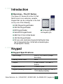
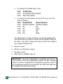
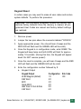
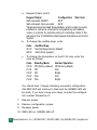
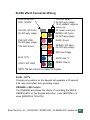
K1 Series
○ ○ ○ ○ ○
All-In-One 12-Pad
INSTALLATION & INSTRUCTION MANUAL
Essex Electronics, Inc. | 805.684.7601 | 800.KEY-LESS | fax 805.684.0232 | keyless.com
K1 Series All-In-One 12-Pad
Multi-Format Keypad Reader
All rights reserved. No part of this documentation may be reproduced in
any form, without prior written consent of Essex Electronics, Inc. Essex
Electronics shall not be liable for errors contained in this manual. The
information in this document is subject to change without notice. Essex
Electronics, Inc. reserves the right to modify this documentation and to
make improvements or changes to the product(s) contained in this
documentation at any time.
Document Information
IOMK1 Installation/Operations Manual for the K1 Series All-In-One 12-Pad
3x4 and 2x6 - August 2007. This documentation is also applicable to prior
revisions except where noted.
Product Information
This device complies with Part 15 of the FCC rules. Operation is subject to
the following two conditions: (1) This device may not cause harmful
interference, and (2) this device must accept any interference including
interference that may cause undesired operation.
Trademarks
Keyless Entry® is a registered trademark of Essex Electronics, Inc.
Contact Information
Essex Electronics, Incorporated
1130 Mark Avenue, Carpinteria, CA 93013
(805) 684-7601 or (800) 539-5377 (KEY-LESS)
FAX (805) 684-0232
Website: keyless.com
General email: [email protected]
Technical Support email: [email protected]
Copyright© 2005 Essex Electronics, Inc. All rights reserved.
i
Essex Electronics, Inc. | 805.684.7601 | 800.KEY-LESS | fax 805.684.0232 | keyless.com
○ ○ ○ ○ ○
Table of Contents
Introduction .................................................................................. 1
Overview - The K1 Series ............................................................. 1
Keypad ........................................................................................... 1
Keypad Specifications ................................................................... 1
Keypad Part Numbers ................................................................... 2
Keypad Configuration .................................................................... 3
26 Bit Wiegand Keypad Reader .................................................. 7
26 Bit Wiegand Specifications ....................................................... 7
26 Bit Wiegand Connector Wiring ................................................. 9
8 Bit Word Keypad Reader ........................................................ 11
8 Bit Word Specifications ............................................................. 11
8 Bit Word Connector Wiring ....................................................... 12
BCD Keypad Reader .................................................................. 14
BCD Specifications ...................................................................... 14
BCD Connector Wiring ................................................................ 15
Serial ASCII Keypad Reader ...................................................... 16
Serial ASCII Specifications .......................................................... 16
Serial ASCII Connector Wiring .................................................... 19
ABA Track II Clock & Data Reader ............................................ 20
ABA Track II Specifications ......................................................... 20
ABA Track II Connector Wiring .................................................... 21
4 Bit Word Keypad Reader .................................................. 22
4 Bit Word Specifications ....................................................... 22
4 Bit Word Connector Wiring ................................................. 23
Warranty & Repairs .................................................................... 28
Essex Electronics, Inc. | 805.684.7601 | 800.KEY-LESS | fax 805.684.0232 | keyless.com ii
iii Essex Electronics, Inc. | 805.684.7601 | 800.KEY-LESS | fax 805.684.0232 | keyless.com
○ ○ ○ ○
Introduction
!
Overview – The K1 Series
The Essex K1 Series All-In-One 12-Pad
Multi-Format is an extremely versatile
Keypad that can be configured in the field
as any one of the following:
! 26 Bit Wiegand Keypad Reader
! 8 Bit Word Keypad Reader
! BCD Keypad Reader
3x4 Keypad (left) and
2x6 Keypad (right)
!
! Serial ASCII Keypad Reader
! ABA Track II Clock & Data Reader
! 4 Bit Word Keypad Reader
! 500 user-code, stand-alone Keyless Entry® System (See
the “K1 Series All-In-One 12-Pad Self-contained Keyless
Entry® System” manual)
○ ○ ○ ○
Keypad
!
Keypad Specifications
Input Voltage:
Standby Current Draw:
Outputs:
Keypad Switch Life:
Keypad Operating Environment:
5VDC or 12 to 24VDC (Jumper
Selectable)
25mA
4 Open Collector, 1/4 A Max to
Ground
>1 Billion Cycles
-40°C to +70°C (-40°F to +160°F),
100% Relative Humidity
Essex Electronics, Inc. | 805.684.7601 | 800.KEY-LESS | fax 805.684.0232 | keyless.com 1
○ ○ ○ ○
Keypad
!
Keypad Specifications, cont’d.
3x4 Keypad Dimensions:
2x6 Keypad Dimensions:
3x4 Keypad Weight:
2x6 Keypad Weight:
LED's:
!
5-1/8"H x 3-3/8"W x 7/16"D
(13 x 8.6 x 1.1 cm)
7-1/8"H x 1-3/4"W x 3/4"D
(13 x 8.6 x 1.1 cm)
16 oz (454 gm)
4.4 oz (125 gm)
1 Red, 1 Green
Keypad Part Numbers
3x4 Keypad
K1-34B
K1-34S
K1-34K
K1-34X
Brass Finished* Bezel
Stainless Steel Bezel
Black Bezel
No Bezel
2x6 Keypad
K1-26B
Brass Overlay
K1-26I
Illuminated
K1-26S
Stainless Steel Overlay
K1-26R
Braille Overlay
*Bezel is brass in appearance. Actual bezel is PVD-coated stainless
steel.
2 Essex Electronics, Inc. | 805.684.7601 | 800.KEY-LESS | fax 805.684.0232 | keyless.com
!
Keypad Configuration
Voltage Selection
The factory default setting for the Keypad voltage is 12-24VDC.
Verify that the jumper is removed or placed over only one pin. For
5VDC, the jumper should be placed across both pins. If changing
the voltage is necessary, make sure the power is removed first.
Keypad Output Selection
Once the voltage jumper is verified or correctly set:
1. Remove power.
2. Jumper the two pins above the connector labeled "CONFIG.”
3. Apply appropriate power. (You should hear 4 beeps and the
RED LED will flash and the GREEN LED will be solid.)
4. Now that the Keypad is in configuration mode, select the
desired output by entering the configuration number followed
by #.
a. Keypad Output
Keypad Output
Configuration Site Code
26 Bit Wiegand (default)
1#
000
8 Bit Word
2#
BCD
3#
Serial ASCII
4#
ABA Track II Clock & Data
5#
4 Bit Word
6#
Self-contained- ERM-3*
98 #
Self-contained- Non-encoded
99 #
*Requires Essex Encoded Relay Module, which contains a serial
interface to connect a computer for programming and reading
codes, or a printer for real-time print-out of activities. Refer to the
manual for the “K1-ERM Encoded Keyless Entry® Access Control
System.”
Essex Electronics, Inc. | 805.684.7601 | 800.KEY-LESS | fax 805.684.0232 | keyless.com 3
b. To change the audible beep, enter
Code
201 #
200 #
c.
Audible Beep
Normal Beep (factory default)
Short Click (quieter)
To change the illumination on the K1-26 only, enter the
code as follows:
Code
210 #
211 #
212 #
213 #
214 #
Standby Mode
Off (factory default)
Off
Off
Dim
Dim
Normal Operation
Off (factory default)
Dim
Bright
Dim
Bright
You should hear 3 beeps indicating successful configuration
(the RED LED will continue to flash and the GREEN LED will
be solid). If you hear a long error beep, re-enter the configuration number followed by #.
5. Remove power.
6. Remove configuration jumper.
7. Re-apply power.
8. RED LED on, GREEN LED off.
IMPORTANT: Once the configuration is selected, you must remove power, remove the configuration jumper and then re-apply
power in order to complete the configuration procedure. Note: If
the configuration jumper is not removed, the LED's will flash and
the Keypad will beep continuously.
4 Essex Electronics, Inc. | 805.684.7601 | 800.KEY-LESS | fax 805.684.0232 | keyless.com
Keypad Reset
In certain cases you may want to erase all user codes and restore
system defaults. To perform this procedure:
CAUTION: This procedure completely erases the memory and
restores factory defaults! Once the memory is cleared, all programmed User Codes are erased and factory default settings
are restored.
1. Remove power.
2. Jumper the two pins above the connector labeled "CONFIG.”
3. Apply appropriate power. (You should hear 4 beeps and the
RED LED will flash and the GREEN LED will be solid).
4. Once the Keypad is in configuration mode, enter 0099#. The
Keypad will beep twice and both LEDS will flash for approximately 10 seconds. (During this time, the Keypad will appear
dead. Do NOT remove power!)
5. Once the reset is complete, you will hear 4 beeps and the RED
LED will flash and the GREEN LED will be solid.
6. Enter the configuration number followed by #.
a. Keypad Output
Keypad Output
26 Bit Wiegand (default)
8 Bit Word
BCD
Serial ASCII
ABA Track II Clock & Data
4 Bit Word
Configuration Site Code
1#
000
2#
3#
4#
5#
6#
Essex Electronics, Inc. | 805.684.7601 | 800.KEY-LESS | fax 805.684.0232 | keyless.com 5
a. Keypad Output cont’d.
Keypad Output
Configuration Site Code
Self-contained- ERM-3*
98 #
Self-contained- Non-encoded
99 #
*Requires Essex Encoded Relay Module, which contains a serial
interface to connect a computer for programming and reading
codes, or a printer for real-time print-out of activities. Refer to the
manual for the “K1-ERM Encoded Keyless Entry® Access Control
System.”
b. To change the audible beep, enter
Code
201 #
200 #
c.
Audible Beep
Normal Beep (factory default)
Short Click (quieter)
To change the illumination on the K1-26 only, enter the
code as follows:
Code
210 #
211 #
212 #
213 #
214 #
Standby Mode
Off (factory default)
Off
Off
Dim
Dim
Normal Operation
Off (factory default)
Dim
Bright
Dim
Bright
You should hear 3 beeps indicating successful configuration
(the RED LED will continue to flash and the GREEN LED will
be solid). If you hear a long error beep, re-enter the configuration number followed by #.
7. Remove power.
8. Remove configuration jumper.
9. Re-apply power.
10. RED LED on, GREEN LED off.
6 Essex Electronics, Inc. | 805.684.7601 | 800.KEY-LESS | fax 805.684.0232 | keyless.com
○ ○ ○ ○ ○
26 Bit Wiegand Keypad Reader
!
26 Bit Wiegand Specifications
The All-In-One 12-Pad is capable of generating standard 26 Bit
Wiegand data. DATA 1 and DATA 0 signals are open collector
outputs with 2.2K pull-ups to the internal +5v. The data is sent at
1 msec per bit with a pulse duration of 50 usec. An annunciator
beeps with each key press. When the LED control input is pulled
low, the GREEN LED will be on and the RED LED will be off.
When the input goes high the RED LED is on and the GREEN
LED is off. The LED that is illuminated will blink off with every key
press. The LED control input is pulled to the internal +5v with a
2.2K resistor. An output is generated with each key press, which
can be used to drive a CCTV or Security Light. Located through
the Blue wire (see Connector Wiring), this is an open collector
output capable of sinking 1/4 A with a 30 second on time.
The following WIEGAND output is sent each time the # (enter) key
is pressed:
PSSSSSSSS NNNNNNNNNNNNNNN N P
BIT 1 2
9 10
25 26
! BIT 1 is an even parity for the following 12 bits.
! The sum of bits 1-13 is even.
! BITS 2-9 are the SITE CODE.
! BITS 10-25 This is the number(PIN) entered prior to pressing #
(enter).
! Leading 0’s are added as required. Bit 10 is most significant.
! BIT 26 is an odd parity over the previous 12 bits. The sum of bits 1426 is odd.
Essex Electronics, Inc. | 805.684.7601 | 800.KEY-LESS | fax 805.684.0232 | keyless.com 7
Example: Site Code of 004 and a code of 123 entered
10000010000000000011110111
Note: An error code, which sends all binary 1’s to your panel,
is generated by any of the following:
a. Pressing the # key with no preceding digits.
b. Pressing any number of only 0’s prior to pressing the #
key.
c.
Pressing 65,535 or any number above 65,535. Do NOT
program your panel to accept code number 65,535.
8 Essex Electronics, Inc. | 805.684.7601 | 800.KEY-LESS | fax 805.684.0232 | keyless.com
!
26 Bit Wiegand Connector Wiring
CONFIGURATION
PINS- “CONFIG”
YELLOW- Audio Control
(Do NOT apply voltage)
PINK- Site Code PGM
(Do NOT apply voltage)
TAN- Earth Ground
VOLTAGE SELECT
(Do NOT apply voltage)
12-24V (default)- Jumper on
one pin only
5V- Jumper on both pins
BROWN- LED Control
(Do NOT apply voltage)
BLACK- Ground
ORANGE- Buffered Input
(Do NOT apply voltage)
RED- Input Voltage
BLUE- CCTV
VIOLET- NOT USED
WHITE- Data 1’s
GREEN- Data 0’s
NOTE: The 2x6 connector is rotated 180 degrees
PINK- Site Code Program
This Keypad is capable of having the SITE CODE programmed in
the field. The PINK wire is used for this procedure.
! With no voltage applied to the Keypad, connect the PINK wire to
the BLACK wire on the wiring harness. Apply the appropriate
voltage to the RED and BLACK wires. You will hear 4 rapid audible
beeps and both the RED and GREEN LED’s will flash at the same
rate.
! Enter the desired SITE CODE (between 0 and 255) on the
Keypad and press # for enter. You will again hear 4 rapid audible
beeps.
Essex Electronics, Inc. | 805.684.7601 | 800.KEY-LESS | fax 805.684.0232 | keyless.com 9
! At this point the Keypad will appear non-functional and will not
accept any entries. (If the wrong key is pressed during the programming sequence, pressing the * key will clear the entry. You
will then hear 2 rapid beeps and both LED’s will flash at the same
rate. The Keypad will generate an error tone if you enter a SITE
CODE over 255.)
! Disconnect power to the RED wire and disconnect the PINK wire
from the BLACK wire.
Now you can connect the standard Wiegand 5 wires to the Keypad
and the programmed SITE CODE will be generated as part of the
26 Bit data when the enter key (#) is pressed.
This procedure may be repeated to change the SITE CODE.
The factory default site code is 000.
BLUE- CCTV
Pressing any position on the Keypad will generate a 30-second,
0.25 Amp, intermittent duty grounding output on the BLUE wire.
ORANGE- Buffered/Hold Line
When the Hold Line or ORANGE wire is pulled low, codes entered
on the Keypad are stored in the buffer. When the Hold Line is
released to a logic high, the buffered code is sent. This input is
pulled high with a 2.2K resistor.
YELLOW- Audio Control
Pulling YELLOW low (grounding) causes the beeper to sound.
TAN- Case Ground
In higher static prone areas, the TAN wire is used to divert static
discharge away from the microprocessor in the Keypad. Ideally,
the TAN wire should be connected to a known Earth Ground at the
Keypad installation point (Do NOT run back to the panel through
the cable).
10 Essex Electronics, Inc. | 805.684.7601 | 800.KEY-LESS | fax 805.684.0232 | keyless.com
○ ○ ○ ○ ○
8 Bit Word Keypad Reader
!
8 Bit Word Specifications
DATA 1 and DATA 0 signals are open collector outputs with 2.2K
pull-ups to the internal +5V. The data is sent at 1 msec per bit with
a pulse duration of 50 usec. An annunciator beeps with each key
press. An output is generated with each key press which can be
used to drive a CCTV or Security Light. Located through the BLUE
wire (see Connector Wiring), this is an open collector output
capable of sinking 1/4 A with a 30 second on time.
Each key press generates an 8-Bit sequence in the following
output format:
KEY
0
1
2
3
4
5
OUTPUT
11110000
11100001
11010010
11000011
10110100
10100101
KEY
6
7
8
9
*
#
OUTPUT
10010110
10000111
01111000
01101001
01011010
01001011
Essex Electronics, Inc. | 805.684.7601 | 800.KEY-LESS | fax 805.684.0232 | keyless.com 11
!
8 Bit Word Connector Wiring
CONFIGURATION
PINS- “CONFIG”
YELLOW- LED Control
(Do NOT apply voltage)
PINK- NOT USED
(Do NOT apply voltage)
TAN- Earth Ground
VOLTAGE SELECT
(Do NOT apply voltage)
12-24V (default)- Jumper on
one pin only
5V- Jumper on both pins
BROWN- LED Control
(Do NOT apply voltage)
BLACK- Ground
ORANGE- LED Select
(Do NOT apply voltage)
RED- Input Voltage
BLUE- CCTV
WHITE- Data 1’s
VIOLET- NOT USED
GREEN- Data 0’s
NOTE: The 2x6 connector is rotated 180 degrees
BLUE - CCTV
Pressing any position on the Keypad will generate a 30 second
0.25 amp intermittent duty grounding output.
ORANGE - LED Control
The ORANGE wire allows the choice of controlling the RED &
GREEN LED’s on the Keypad with either 1 wire (BROWN) or 2
wires (BROWN & YELLOW).
12 Essex Electronics, Inc. | 805.684.7601 | 800.KEY-LESS | fax 805.684.0232 | keyless.com
ORANGE - LED Control, cont’d.
a. When the ORANGE wire is floating (not connected), two wires
control the LED’s. When the BROWN wire is pulled low
(grounded), the GREEN LED is on. When the YELLOW wire is
pulled low, the RED LED is on.
b. To control both LED’s with one wire (BROWN), pull the
ORANGE wire low. When the LED control input is pulled low,
the GREEN LED will be on and the RED LED will be off. When
the input goes high, the RED LED will be on and the GREEN
LED will be off. The LED that is illuminated will blink with every
key press. The LED control is pulled to the internal +5 with a
2.2K resistor.
Essex Electronics, Inc. | 805.684.7601 | 800.KEY-LESS | fax 805.684.0232 | keyless.com 13
○ ○ ○ ○ ○
BCD Keypad Reader
!
BCD Specifications
An Output is generated with each key press with a pulse duration
of 75 msec. If a longer pulse width is required, grounding the PINK
wire on the connector will increase the pulse width to 150 msec.
An annunciator beeps with each key press.
The output is BCD SINKING with internal 2.2K ohm pull-up
resistors. If a BCD SOURCING output is required, grounding the
ORANGE wire on the connector will convert the output to BCD
SOURCING thru 2.2K ohm resistors. The resistors are pulled up
to the internal 5V.
The BCD outputs are:
1
2
4
8
GREEN
WHITE
VIOLET
BLUE
! Position “0” is sent as a 10
! Position “*” is sent as an 11
! Position “#” is sent as a 12
14 Essex Electronics, Inc. | 805.684.7601 | 800.KEY-LESS | fax 805.684.0232 | keyless.com
!
BCD Connector Wiring
CONFIGURATION
PINS- “CONFIG”
YELLOW- RED LED
Control (Do NOT apply
voltage)
PINK- Pulse Width Select
(Do NOT apply voltage)
VOLTAGE SELECT
(Do NOT apply voltage)
12-24V (default)- Jumper on
one pin only
5V- Jumper on both pins
BROWN- GREEN LED Control
(Do NOT apply voltage)
TAN- Earth Ground
BLACK- Ground
ORANGE- Sinking / Sourcing
output Select (Do NOT apply
voltage)
RED- Input Voltage
BLUE- BCD 8
WHITE- BCD 2
VIOLET- BCD 4
GREEN- BCD 1
NOTE: The 2x6 connector is rotated 180 degrees
YELLOW - Red LED
Grounding the YELLOW wire on the connector will illuminate the
RED LED. (Do NOT apply voltage.)
BROWN - Green LED
Grounding the BROWN wire on the connector will illuminate the
GREEN LED. (Do NOT apply voltage.)
RED - Input Voltage
The input voltage is 5V or 12-24V.
TAN - Earth Ground
The TAN wire or Earth Ground should be connected to a good
ground close to the Keypad.
Essex Electronics, Inc. | 805.684.7601 | 800.KEY-LESS | fax 805.684.0232 | keyless.com 15
○ ○ ○ ○ ○
Serial ASCII Keypad Reader
!
Serial ASCII Specifications
Normal Serial and Inverted Serial signals are open collector
outputs with 2.2K pull-ups to the internal +5v. An annunciator
beeps with each key press. When the LED control input is pulled
low, the GREEN LED will be on and the RED LED will be off.
When the input goes high, the RED LED is on and the GREEN
LED is off. The RED LED will blink with every key press. The LED
control input is pulled to the internal +5v with a 2.2K resistor. An
output is generated with each key press which can be used to
drive a CCTV or Security Light. Available through the BLUE wire
(see Connector Wiring), this is an open collector output capable of
sinking 1/4 A with a 30 second on time. The PINK wire is used to
modify the Keypad baud rate, parity and mode. This can be
accomplished in the field.
Modifying the Baud Rate, Parity and Mode
1. Baud Rate (first digit)
With no voltage applied to the Keypad, connect the PINK wire
to the BLACK wire on the wiring harness. Apply the appropriate voltage to the RED and BLACK wires. You will hear 4 rapid
audible beeps and both the RED and GREEN LED’s will flash
at the same rate. Enter the desired first digit on the Keypad to
select the baud rate:
1 = 300
2 = 600
3 = 1200
4 = 2400
5 = 4800
6 = 9600
7 = 19200
8 = 38400
Note: All baud rates have a timing error of < 0.2% + Xtal Freq
Error.
16 Essex Electronics, Inc. | 805.684.7601 | 800.KEY-LESS | fax 805.684.0232 | keyless.com
If the wrong baud rate is selected, pressing the * key before
entering the parity option will clear the entry. The Keypad will
generate an error tone if you enter an invalid number. You
should hear 2 audible beeps and the RED LED will continue
blinking fast while the GREEN LED will blink slow.
2. Parity Option (second digit)
Next, enter the desired second digit on the Keypad to select
the parity option:
0 = None (8 Data Bits)
1 = Odd (7 Data Bits + Odd Parity Bit)
2 = Even (7 Data Bits + Even Parity Bit)
Note: All Parity formats have a single Start and Stop Bit.
If the wrong parity is selected, pressing the * key before
entering the mode option will clear the entry. The Keypad will
generate an error tone if you enter an invalid number. You
should hear 2 audible beeps and the RED LED will continue
blinking fast while the GREEN LED will be solid.
3. Mode (third digit)
To select the desired mode option, enter the desired third digit
on the Keypad:
0 = NORMAL (Single character output with each keystroke)
*Sends ASCII* - #Sends ASCII#
1 = ALTCHAR (Single character output with each keystroke)
*Sends ASCII <ESC> - # Sends ASCII <CR>
2 = BUFFER
BUFFER mode accepts up to 10 characters. If more than 10 characters are entered, you will hear an error beep and the buffer will be
cleared. Pressing # sends buffered characters + ASCII <CR> at end.
Pressing * clears the buffer and outputs 2 beeps. Clear buffer timeout
set to 10 seconds.
Essex Electronics, Inc. | 805.684.7601 | 800.KEY-LESS | fax 805.684.0232 | keyless.com 17
You should hear 3 rapid audible beeps and see both LED’s
extinguish. At this point the Keypad will appear dead and not
accept any entries.
Examples:
3 1 0 (Sets 1200 baud, odd pariety and normal mode)
7 0 2 (Sets 19200 baud, no pariety and buffered mode)
This procedure may be repeated to change the Baud Rate and
Parity option. You must enter all three digits even if you wish to
change only one setting. Factory default is 9600 baud, no parity,
normal.
Disconnect power to the RED wire and disconnect the PINK wire
from the BLACK wire.
NORMAL mode outputs the following codes:
0 - 0x30
6 - 0x36
1 - 0x31
7 - 0x37
2 - 0x32
8 - 0x38
3 - 0x33
9 - 0x39
4 - 0x34
* - 0x2A
5 - 0x35
# - 0x23
ALTCHAR mode outputs the following codes:
0 - 0x30
6 - 0x36
1 - 0x31
7 - 0x37
2 - 0x32
8 - 0x38
3 - 0x33
9 - 0x39
4 - 0x34
* - 0x1B
5 - 0x35
# - 0x0D
Note: All serial output formats use a single start and stop bit.
18 Essex Electronics, Inc. | 805.684.7601 | 800.KEY-LESS | fax 805.684.0232 | keyless.com
! Serial ASCII
Connector Wiring
CONFIGURATION
PINS- “CONFIG”
YELLOW- Audio Control
(Do NOT apply voltage)
PINK- Baud / Parity / Mode
Select (Do NOT apply
voltage)
TAN- Earth Ground
VOLTAGE SELECT
(Do NOT apply voltage)
12-24V (default)- Jumper on
one pin only
5V- Jumper on both pins
BROWN- LED Control
(Do NOT apply voltage)
BLACK- Ground
ORANGE- NOT USED
(Do NOT apply voltage)
RED- Input Voltage
BLUE- CCTV
VIOLET- NOT USED
WHITE- Inverted Serial Output
GREEN- Normal Serial Output
NOTE: The 2x6 connector is rotated 180 degrees
BLUE - CCTV
Pressing any position on the Keypad will generate a 30 second
0.25 amp intermittent duty grounding output.
YELLOW- Audio Control
Pulling YELLOW low (grounding) causes the beeper to sound.
TAN - Earth Ground
Case ground at the Keypad installation point, not through the
cable.
Typical connection: WHITE to Pin 2 of DB-9 (232 RX), BLACK to
Pin 5, and Power Supply Ground.
Essex Electronics, Inc. | 805.684.7601 | 800.KEY-LESS | fax 805.684.0232 | keyless.com 19
○ ○ ○ ○ ○
ABA Track II Clock & Data Reader
! ABA Track
II Specifications
GREEN <Clock> goes low to clock in data. WHITE <Data> output
is determined by ORANGE. If ORANGE is low, then Data output is
inverted. If ORANGE is high, then Data output is normal.
Clock and Data signals are open collector outputs with 2.2K pullups to the internal +5v. Clock Pulse is sent at 200 usec. Interbit
delay is 750 usec. An annunciator beeps with each key press. An
output is generated with each key press which can be used to
drive a CCTV or Security Light. Located through the BLUE wire
(see Connector Wiring), this is an open collector output capable of
sinking 1/4 A with a 30 second on time.
Each key press generates an ABA Data Format as follows:
1. Each character is sent as a 5 bit value. The first 4 bits of each
character are the data value LSB first. The last bit of each
character is an odd parity bit. The first four 0’s are sent as lead
in.
2. The Start Character is sent next. The Start Character is a “B”
with odd parity bit. Each entered character is now sent as 5
bits per character with odd parity and LSB first. There can be
up to a max of 12 characters.
3. After all the keyed in characters have been sent, then the End
Sentinel is sent. The End Sentinel is an “F” with odd parity.
Next the LRC code is sent as a 5 bit character with odd parity.
The LRC code is created by XORing all of the characters sent
including the Start Characters, the Digit Characters and the
End Sentinel. It is calculated as a 4 bit value from XORing all
the previous characters. Its value is then sent as a 5 bit value,
the 5th bit being its own odd parity.
20 Essex Electronics, Inc. | 805.684.7601 | 800.KEY-LESS | fax 805.684.0232 | keyless.com
4. Finally 7 0 bits are sent as lead out.
Notes:
! # is the Enter key and * is the Clear key. If # is pressed with no data
key first, there is no output from the keypad.
! If over 12 data keys are pressed before enter, there is no output from the
keypad.
! ABA Track
II Connector Wiring
CONFIGURATION
PINS- “CONFIG”
YELLOW- RED LED
Control (Do NOT apply
voltage)
PINK- NOT USED
(Do NOT apply voltage)
TAN- Earth Ground
VOLTAGE SELECT
(Do NOT apply voltage)
12-24V (default)- Jumper on
one pin only
5V- Jumper on both pins
BROWN- GREEN LED Control
(Do NOT apply voltage)
BLACK- Ground
ORANGE- Invert Data Output
(Do NOT apply voltage)
RED- Input Voltage
BLUE- CCTV
VIOLET- NOT USED
WHITE- Data
GREEN- Clock
NOTE: The 2x6 connector is rotated 180 degrees
Essex Electronics, Inc. | 805.684.7601 | 800.KEY-LESS | fax 805.684.0232 | keyless.com 21
○ ○ ○ ○ ○
4 Bit Word Keypad Reader
!
4 Bit Word Specifications
DATA 1 and DATA 0 signals are open collector outputs with 2.2K
pull-ups to the internal +5V. The data is sent at 1 msec per bit with
a pulse duration of 50 usec. An annunciator beeps with each key
press. An output is generated with each key press which can be
used to drive a CCTV or Security Light. Located through the BLUE
wire (see Connector Wiring), this is an open collector output
capable of sinking 1/4 A with a 30 second on time.
Each key press generates an 4-Bit sequence in the following
output format:
KEY
0
1
2
3
4
5
OUTPUT
0000
0001
0010
0011
0100
0101
KEY
6
7
8
9
*
#
OUTPUT
0110
0111
1000
1001
1010
1011
22 Essex Electronics, Inc. | 805.684.7601 | 800.KEY-LESS | fax 805.684.0232 | keyless.com
!
4 Bit Word Connector Wiring
CONFIGURATION
PINS- “CONFIG”
YELLOW- LED Control
(Do NOT apply voltage)
PINK- NOT USED
(Do NOT apply voltage)
TAN- Earth Ground
VOLTAGE SELECT
(Do NOT apply voltage)
12-24V (default)- Jumper on
one pin only
5V- Jumper on both pins
BROWN- LED Control
(Do NOT apply voltage)
BLACK- Ground
ORANGE- LED Select
(Do NOT apply voltage)
RED- Input Voltage
BLUE- CCTV
WHITE- Data 1’s
VIOLET- NOT USED
GREEN- Data 0’s
NOTE: The 2x6 connector is rotated 180 degrees
BLUE - CCTV
Pressing any position on the Keypad will generate a 30 second
0.25 amp intermittent duty grounding output.
ORANGE - LED Control
The ORANGE wire allows the choice of controlling the RED &
GREEN LED’s on the Keypad with either 1 wire (BROWN) or 2
wires (BROWN & YELLOW).
Essex Electronics, Inc. | 805.684.7601 | 800.KEY-LESS | fax 805.684.0232 | keyless.com 23
ORANGE - LED Control, cont’d.
a. When the ORANGE wire is floating (not connected), two wires
control the LED’s. When the BROWN wire is pulled low
(grounded), the GREEN LED is on. When the YELLOW wire is
pulled low, the RED LED is on.
b. To control both LED’s with one wire (BROWN), pull the
ORANGE wire low. When the LED control input is pulled low,
the GREEN LED will be on and the RED LED will be off. When
the input goes high, the RED LED will be on and the GREEN
LED will be off. The LED that is illuminated will blink with every
key press. The LED control is pulled to the internal +5 with a
2.2K resistor.
24 Essex Electronics, Inc. | 805.684.7601 | 800.KEY-LESS | fax 805.684.0232 | keyless.com
○ ○ ○ ○ ○
Notes
Essex Electronics, Inc. | 805.684.7601 | 800.KEY-LESS | fax 805.684.0232 | keyless.com 25
○ ○ ○ ○ ○
Notes
26 Essex Electronics, Inc. | 805.684.7601 | 800.KEY-LESS | fax 805.684.0232 | keyless.com
○ ○ ○ ○ ○
Notes
Essex Electronics, Inc. | 805.684.7601 | 800.KEY-LESS | fax 805.684.0232 | keyless.com 27
○ ○ ○ ○ ○
Warranty & Repairs
!
Limited Lifetime Warranty
(effective date May 1, 2006)
Essex Electronics Inc. warrants that at the time of original
purchase from Essex Electronics Inc., the products specified below
are free from defects in workmanship and material. Subject to the
conditions and limitations set forth below, Essex Electronics Inc.
will, at its option, either repair or replace any part of its products
that prove defective by reason of improper workmanship or
materials. Repaired parts or replacement products will be provided
by Essex Electronics Inc. on an exchange basis, and will be either
new or refurbished to be functionally equivalent to new. Essex
Electronics Inc. reserves the right to discontinue a product for any
reason, without notice, at any time. If a product that has been
discontinued proves defective and if Essex Electronics Inc. is
unable to repair or replace the product, within the terms expressed
in this Limited Lifetime Warranty, a substitute product may be
provided at the Essex Electronics Inc.’s election, as a replacement
for the original discontinued product.
This Limited Lifetime Warranty extends only to the original retail or
wholesale Buyer and the original site of installation. It does not
cover any damage to this product or parts thereof, if the product is
installed in violation of the applicable codes or ordinances, or is
not installed in accordance with our installation instructions. This
warranty will only include the normal operating life of the LED’s
which will be 10 years from the date of the original sale. It does not
cover any damage that results from accident, abuse, misuse,
natural disaster, insufficient or excessive electrical supply, abnormal mechanical or environmental conditions, or any unauthorized
disassembly, repair, or modification. This Limited Lifetime Warranty
28 Essex Electronics, Inc. | 805.684.7601 | 800.KEY-LESS | fax 805.684.0232 | keyless.com
also does not apply to any product on which the original identification or date of manufacture information has been altered, obliterated or removed. In no event shall Essex Electronics Inc. be liable
for any damage to persons, property or area surrounding the
installation site caused by any malfunction of the product manufactured by Essex Electronics Inc.
Essex Electronics Inc. will not pay, nor be responsible for, shipping,
transportation or delivery charges, or other cost of removal of a
defective product or installation of a replacement product. The
original component replaced under this Limited Lifetime Warranty
in any system shall become the property of Essex Electronics Inc.,
and as such will, at our request, be returned to our factory with
transportation charges paid by the Buyer.
Limited Lifetime Warranty
The Essex Electronics Inc. products with a manufactured date of 5/
1/06 to the present date that are covered by this Limited Lifetime
Warranty are Keypads, Keyless Entry Access Control Systems and
accessories.
Essex Electronics, Inc.’s liability and Buyer’s remedy under this
warranty is limited to the repair or replacement at Seller’s election
of the product, or parts thereof, returned to Essex Electronics Inc.
at Buyer’s expense and shown to Essex Electronics Inc.’s reasonable satisfaction to have been defective.
Notice of any defect must be sent to Essex Electronics, Inc., 1130
Mark Avenue, Carpinteria, California, 93013, USA and must
include the date code of the unit, description of the defect and
factory assigned Return Authorization #. Upon receipt of such
notification, Essex will determine whether to repair or replace. We
also reserve the right to have our representative make any inspection or repairs, or furnish replacements.
Essex Electronics, Inc. | 805.684.7601 | 800.KEY-LESS | fax 805.684.0232 | keyless.com 29
This warranty excludes Elevator and Vehicle Keyless Entry Access
Control Systems. A separate warranty applies to Keyless Entry
systems manufactured for these applications.
Disclaimer of Warranties: Limitation of Buyer’s Remedies
Except for the repair or replacement at seller’s option which is
expressly set forth above, Essex Electronics Inc. extends no
warranty of any kind, express or implied, and disclaims any implied
warranty of merchantability or suitability for purpose for which sold,
with respect to the keypads, keyless entry coded access system or
accessories. Except for the limited repair or replacement specified
above, under no circumstances will Essex Electronics Inc. be
liable to buyer under or in connection with any manufacture or sale
of any of the products set forth above under any tort, negligence,
strict liability, contract or other legal or equitable theory, or for
incidental or consequential damages, or buyer’s cost of effecting
insurance coverage.
The foregoing limited lifetime warranty expressed herein constitutes the sole and entire warranty with respect to the products set
forth above and is in place of any and all other warranties, express
or implied.
This warranty may not be expanded or extended by any oral
representation, written sales information, advertising, drawings or
otherwise. Essex Electronics Inc. is not responsible hereunder for
incidental damage to person or property, or other incidental or
consequential damages. The remedies of the buyer shall be
limited to those provided in this limited lifetime warranty to the
exclusion of any and all other remedies, including, without limitation, incidental or consequential damages.
This Limited Lifetime Warranty shall be governed by and interpreted in accordance with the California Uniform Commercial
Code and by the procedural laws of the State of California. Any
30 Essex Electronics, Inc. | 805.684.7601 | 800.KEY-LESS | fax 805.684.0232 | keyless.com
lawsuit or other action which arises out of, relates to, or is in
connection with the manufacture or sale of the products set forth
above shall be governed by California law, and the venue for any
such action shall be the Superior Court of the State of California in
and for Santa Barbara County, California.
! Repair
Policy
Should it be necessary for a component or a system to be returned for repair, it must be accompanied with an RA# (Return
Authorization Number) issued by the factory. Please call 1-800KEYLESS (800-539-5377) to obtain an RA#. All returns must be
sent to the factory freight prepaid. Collect shipments will not be
accepted at any time. Standard turnaround time is ten (10) working
days from the date of receipt. Repaired components will be
returned UPS Ground (or equivalent). Any other shipping requests
or instructions will be at the customer’s expense.
At the factory’s discretion, warranty repairs will include repair or
replacement, update and testing. Returns and repairs out of the
warranty period or in warranty with damage not covered under
warranty shall be subject to a repair charge. All non-warranty
repair freight charges are paid for by the customer. Non-warranty
repair charges are returned COD. (Factory Authorized Distributors
are subject to standard terms).
Essex Electronics, Inc. | 805.684.7601 | 800.KEY-LESS | fax 805.684.0232 | keyless.com 31
○ ○ ○ ○ ○
Essex Electronics, Inc. | 805.684.7601 | 800.KEY-LESS | fax 805.684.0232 | keyless.com