1
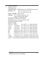
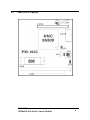
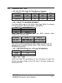
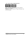
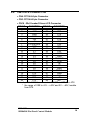
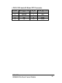
MSI-PM1033 HMC86508 Flat Panel Control Module The information in this document is subject to change without prior notice in order to improve reliability, design and function and does not represent a commitment on the part of the manufacturer. In no event will the manufacturer be liable for direct, indirect, special, incidental, or consequential damages arising out of the use or inability to use the product or documentation, even if advised of the possibility of such damages. This document contains proprietary information protected by copyright. All rights are reserved. No part of this manual may be reproduced by any mechanical, electronic, or other means in any form without prior written permission of the manufacturer. Contents 1. Introduction....................................................................... 2 1.1 Specifications ..............................................................3 2. Installation ........................................................................ 4 2.1 PM-1033's Layout .......................................................6 2.2 Unpacking Precautions… … … … … … … … … … … … … . ..........................7 2.3 JUMPER SETTING .....................................................8 2.4 PM-1033'S CONNECTOR.........................................10 PM-1033 HM86508 Flat Panel Control Module 1 1 Introduction Welcome to the PM-1033 HM86508 Flat Panel Control Module. The PM-1033 is a PC/104 form factor module. It uses HM86508 LCD/CRT Controller Chips to support high resolution LCD/CRT display panel. It is made for the SBCs that are not equipped with LCD/CRT interface from the factory and is the best solution for internal flat panel connection. PM-1033 HM86508 Flat Panel Control Module 2 1.1 Specifications : PC/104 form factor LCD/CRT Interface : HM86508 Chipset with 1MB RAM display memory Resolution: up to 1024 x 768, 256 colors for CRT 800 x 600, 16M colors for LCD Output +/-40V VEE for flat panel need LCD Type : TFT or DSTN (selectable from JP5) Support 18/24-bit data signals Simultaneous VGA and LCD display Flash Disk: support M-Systems Disk On Chip o Operating Temperature: 0-60 C Support LCD Type : Prime View P64CV1 640 x 480 TFT 6.4” (BIOS 5081.HMC) Toshiba LTM10C209A 640 x 480 TFT 10.4” (BIOS 5081.HMC) Toshiba LTM10C273A 800 x 600 TFT 10.4” (BIOS 5082.HMC) Toshiba LTM12C275A 800 x 600 TFT 12.1” (BIOS 5082.HMC) NEC NL8060AC33-13 640 x 480 TFT 10.4” (BIOS 5081.HMC) NEC NL8060AC26-04 800 x 600 TFT 10.4” (BIOS 5082.HMC) NEC NL8060BC31-09 800 x 600 TFT 12.1” (BIOS 5082.HMC) Hitachi LMG9211XUCC 640 x 480 DSTN 9.4”(BIOS 5081/2.HMC) Chunghwa CLX-8102S-C3X 640 x 480 DSTN 9.4” (BIOS 5081/2.HMC) Kyocera KCB104VG2BA-A01640X480 DSTN 10.4”(BIOS 5081/2.HMC) PM-1033 HM86508 Flat Panel Control Module 3 2 Installation This chapter describes how to install the PM-1033. The layout of PM-1033 is shown on the next page and the Unpacking Precautions that you should be careful with are described on the following page. Also included is the jumpers and connectors description for this PM-1033. Hardware Installation : 1. 2. 3. 4. 5. 6. Please read the Unpacking Precautions first before you install the PM-1033 (see page 6). If your LCD panel is TFT type then skip JP7 and JP8 (default setting of JP8 is for TFT type LCD panel) If your LCD panel is MONO or DSTN type, JP7 must be set according to the data sheet of the LCD panel (+VEE or – VEE) then adjust the output of VEE through R19 (Variable Resistor). Caution: don’ t make connection to your LCD panel while you adjust the output of VEE, it may damage your LCD panel. Measure the voltage with a voltage meter. Caution: Don’ t set the JP8 to VEE if your LCD panel is TFT type. It will cause fatal damage to your LCD panel. Select the correct BIOS type for your LCD panel on JP5. Connect your LCD panel cable to CN16 and CRT monitor to CN15. PM-1033 HM86508 Flat Panel Control Module 4 Software (driver) Installation : If this is the first time you install Windows, please plug the PM-1033 into the PC/104 (in POWER OFF condition) then start to install the Windows. After the installation complete, press the button > Settings > Control Panel. Select the Display Icon and then press Settings Menu and press the Advanced button. Press Adapter Menu and then press the Change button. Windows will go into Update Device Driver Wizard, press Next button and then check on: Display a list of all the drivers in a specific location, so you can select the driver you want. Then press Have Disk button and browse or select the correct driver from the diskette. Choose the HM86508 driver from the disk under the NT40, WIN31 or WIN95 directory, depending on the Windows version that you install. For hard disk, which has been installed by another VGA driver before, to update the driver: under Control Panel, select System icon then press Device Manager Menu. Remove the old display adapters and then install the new driver using Add New Hardware wizard under the Control Panel. Consult the Microsoft Windows User Manual for the driver installation. PM-1033 HM86508 Flat Panel Control Module 5 2.1 PM-1033's Layout PM-1033 HM86508 Flat Panel Control Module 6 2.2 Unpacking Precautions ü Some components on PM-1033 are very sensitive to static electric charges and can be damaged by a sudden rush of power. Ground yourself to remove any static charge before touching your PM-1033. You can do it by using a grounded wrist strap at all times or by frequently touching any conducting materials that is connected to the ground. ü Disconnect power supply before handling and doing connection on PM-1033. Do not plug any connector or jumper while the power is on. It will cause fatal damage to your LCD panel. ü Make sure that every connector is connected in correct direction. Any incorrect connection may cause smoke or burn of electrical parts or fatal damage of your LCD panel. PM-1033 HM86508 Flat Panel Control Module 7 2.3 JUMPER SETTING • JP1 JP2 JP3 JP4: Disk On Chip Memory Address FUNCTION CE000H D6000H DE000H JP1 1-2 1-2 1-2 JP2 2-3 2-3 2-3 JP3 2-3 2-3 2-3 JP4 3-4 5-6 7-8 • JP5 : SELECT FLASHROM SEGMENT The Flash ROM used on PM-1033 is 64K Flash ROM. It is divided into two segment, 32K each, BIOS 1 and BIOS 2. JP5 DESCRIPTION 1-2 BIOS 1 2-3 BIOS 2 Note: PM-1033 is equipped with one BIOS diskette which contains the following files: File Name 5081.HMC 5082.HMC BIOS 1 640 x 480 TFT 800 x 600 TFT BIOS 2 640 x 480 DSTN 640 x 480 DSTN PM-1033 is initially installed with 5081.HMC. The BIOS can be programmed or updated with the other *.HMC files by using an EPROM programmer. • JP7 : VEE SELECTION (for LCD type DSTN/MONO) FUNCTION JP7 +VEE 1-2 -VEE 2-3 +VEE = +5V ~ +40V -VEE = -0V ~ -40V User must read the specification of the LCD panel to know the polarity and bias voltage of the LCD panel. The bias voltage can be set from R19. PM-1033 HM86508 Flat Panel Control Module 8 • JP8 : CN16 Pin7 VEE or FPVEE SELECTION FUNCTION JP8 VEE 1-2 FPVEE 2-3 FPVEE = LCD control signal VEE = +/- 40V output (adjustable through R19) for MONO or DSTN type of LCD panel. Caution: don’ t set JP8 to VEE for TFT type of LCD panel, it will cause fatal damage! PM-1033 HM86508 Flat Panel Control Module 9 2.4 PM-1033’S CONNECTOR • CN4: PC104-64 pin Connector • CN3: PC104-40 pin Connector • CN16 : 22x2 header/2.0mm LCD Connector PIN NO FUNCTION PIN NO FUNCTION 1 +12V 23 P14 2 +12V 24 P15 3 GND 25 P16 4 GND 26 P17 5 +5V 27 P18 6 +5V 28 P19 7 FPVEE/VEE 29 P20 8 GND 30 P21 9 P0 31 P22 10 P1 32 P23 11 P2 33 GND 12 P3 34 GND 13 P4 35 SHFCLK 14 P5 36 FLM 15 P6 37 M 16 P7 38 LP 17 P8 39 GND 18 P9 40 ENBKL 19 P10 41 GND 20 P11 42 N/C 21 P12 43 +5V 22 P13 44 N/C Note: * pin 7 of CN16 can be set as FPVEE or VEE from JP8 * the range of VEE is +5V ~ +40V and 0V ~ -40V, tunable from R19 PM-1033 HM86508 Flat Panel Control Module 10 • CN15: 5X2 header/2.54mm CRT Connector PIN NO. DESCRIPTION 1 RED 2 GREEN 3 BLUE 4 HS 5 VS PIN NO. 6 7 8 9 10 PM-1033 HM86508 Flat Panel Control Module DESCRIPTION NC NC GND GND GND 11