1
®
Model No. 831.28622.1
Serial No.
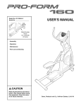
ELLIPTICAL
EXERCISER
User's Manual
Serial
Number
Decal
• Assembly
• Operation
• Maintenance
• Part List and Drawing
Sears, Roebuck and Co., Hoffman Estates, IL 60179
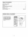
TABLE OF CONTENTS
WARNING DECAL PLACEMENT ..............................................................
IMPORTANT PRECAUTIONS
................................................................
BEFORE YOU BEGIN ......................................................................
ASSEMBLY ...............................................................................
HOW TO USE THE ELLIPTICAL EXERCISER ...................................................
MAINTENANCE AND TROUBLESHOOTING
...................................................
EXERCISE GUIDELINES ...................................................................
PART LIST ..............................................................................
EXPLODED DRAWING ....................................................................
ORDERING REPLACEMENT PARTS ..................................................
90 DAY FULL WARRANTY
..........................................................
2
3
4
5
9
12
13
14
15
Back Cover
Back Cover
WARNING DECAL PLACEMENT
The warning decal shown here has
been applied in the location shown.
If the decal is missing or illegible,
call 1-888-533-1333 and request a
free replacement decal. Apply the
decal in the location shown, Note:
The decal may not be shown at
actual size.
• Misuse of this machine
may result in serious
injury.
, Read user's manual
prior to use and follow
all warnings and
instructions.
, Do net allow children
on or around machine.
• Pedals continue to
spin when you stop
pedaling.
• Spinning pedals can
cause injury.
• Reduce pedal speed
in a controlled manner.
• User weight must not
exceed 250 pounds.
• Replace label if
damaged, illegible, or
removed.
2
!
\
IMPORTANT
PRECAUTIONS
BEFORE
YOU
BEGIN
Congratulations for selecting the new PROFORM ®
15.5 S. The PROFORM 15.5 S is an incredibly
smooth exerciser that moves your feet in a natural
elliptical path, minimizing the impact on your knees
and ankles. And the unique PROFORM 15.5 S features adjustable resistance and a simple-to-use console to help you get the most from your exercise.
tions after reading this manual, please see the back
cover of this manual. To help us assist you, note the
product model number and serial number before contacting us. The model number and the location of the
serial number decal are shown on the front cover of
this manual.
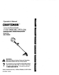
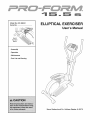
Before reading further, please familiarize yourself with
the parts that are labeled in the drawing below.
For your benefit, read this manual carefully before
you use the elliptical exerciser. If you have ques-
--
Pulse Sensor
Handlebar
--
Fan
--
Console
Water Bottle Holder*
Pedal Disc
Pedal
*No water bottle is included
4
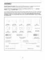
ASSEMBLY
Assembly requires two persons. Place all parts of the elliptical exerciser in a cleared area and remove the
packing materials. Do not dispose of the packing materials until assembly is completed.
Assembly requires the included hex keys and your own Phillips screwdriver _,
wrench o__,
and rubber mallet ___;___{_q
adjustable
I
As you assemble the elliptical exerciser, use the drawings below to identify small parts. The number in parentheses
below each drawing is the key number of the part, from the PART LIST near the end of this manual. The number
following the parentheses is the quantity needed for assembly. Note: Some small parts may have been preassembled. If a part is not in the parts bag, check to see if it has been preassembled. If a part is missing,
call 1-888-533-1333.
\
\\\
\
\
\\\
M8 Split
Washer (28)-4
Wave
Washer (69)-2
M10 Split
Washer (45)-2
Large Wave
Washer (76)-2
M8
Washer (71)-4
M8 Nylon
Locknut (38)-4
Handlebar
Washer (55)-2
M10 Nylon
Locknut (33)-6
MIO
Washer (35)-2
M4 x 22mm
Screw (63)-2
,
M8 x 25mm Patch
Screw (56)-2
M8 x 52mm Button
Screw (27)-4
/
M10 x 27mm
Patch Screw (40)-2
/
M10 x 74mm Button Bolt (7)-2
M8 x 45mm Button Bolt (50)-4
M10 x 75mm Carriage Bolt (34)-4
M6 Bolt Set (25)-2
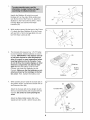
21
34
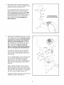
IdentifytheStabilizer(9)whichhasround
Endcaps(21)ontheends.Whileanotherpersonliftsthefrontofthe Frame(1),attachthe
Stabilizertothe FramewithtwoM10x 75mm
CarriageBolts(34)andtwoM10Nylon
Locknuts(33).
34
33
21
Whileanotherpersonliftsthebackof theFrame
(1),attachtheotherStabilizer(9)to theFrame
withtwoM10x 75mmCarriageBolts(34)and
twoM10NylonLocknuts(33).
9
,
4,
The Console (23) requires four 1.5V "D" batteries (not included); alkaline batteries are recommended. IMPORTANT: If the elliptical exerciser has been exposed to cold temperatures,
allow it to warm to room temperature before
inserting batteries into the Console. If you
do not do this, the console displays or other
electronic components
may become damaged. Remove the battery cover from the
Console, and insert four batteries into the
Console. Make sure that the batteries are oriented as shown by the markings on the battery cover. Then, reattach the battery cover.
23
Batteries
Battery
Cover
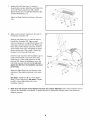
While another person holds the Console (23) in
the position shown, connect the console wire to
the Extension Wire (68).
23
\
Console Wire
Attach the Console (23) to the Upright (2) with
the four Console Screws (59) included with the
Console. Be careful to avoid pinching the
wires.
Attach the Water Bottle Holder (29) to the
Upright (2) with two M4 x 22mm Screws (63).
29
59
6
5.
While another person holds the Upright (2) in
the position shown, connect the Extension Wire
(68) to the Lower Wire Harness (73).
5
45
Push the Extension Wire (68) and the Lower
Wire Harness (73) down into the Frame (1).
Slide the Upright (2) onto the Frame. Be careful to avoid pinching the Wires, Attach the
Upright with two M10 x 74mm Button Bolts (7),
two M10 Split Washers (45), and two M10
Nylon Locknuts (33). Do not tighten the
Button Bolts yet.
,
\
Avoid pinching the
wires during this step
Identify the Left Handlebar (6), which is marked
with a sticker. Insert the Left Handlebar into one
of the Handlebar Legs (5); make sure that the
Handlebar Leg is turned so the hexagonal
holes are on the indicated side. Attach the
Left Handlebar to the Handlebar Leg with two
M8 x 45mm Button Bolts (50) and two M8
Nylon Locknuts (38). Make sure that the
Nylon Locknuts are inside of the hexagonal
holes. Do not tighten the Button Bolts yet,
6
\\
Insert the Pivot Axle (26) into the Upright (2),
and center the Pivot Axle. Apply a generous
amount of the included grease to both ends of
the Pivot Axle.
55
Turn a Handlebar Spacer (47) so that the small
arrow on the Handlebar Spacer is pointing
toward the floor, and slide the Handlebar
Spacer onto the post on the Left Handlebar (6).
Next, slide the Left Handlebar onto the Pivot
Axle (26).
46
Slide a Handlebar Washer (55) and a Wave
Washer (69) onto an M8 x 25mm Patch Screw
(56), and tighten the Patch Screw into the Pivot
Axle (26). Then, press the tabs on a Handlebar
Cap (46) into the Handlebar Spacer (47).
Assemble the Right Handlebar (8) and the other
Handlebar Leg (5) in the same way.
7
\
7.
Identify the Left Pedal Leg (11), which is
marked with a sticker. Attach the Left Pedal (13)
to the Left Pedal Leg with two M8 x 52mm
Button Screws (27), two M8 Split Washers (28),
and two M8 Washers (71).
7
Attach the Right Pedal (not shown) in the same
way.
11
Apply a small amount of grease to the axle on
the left Disc Crossbar (16).
Slide the Left Pedal Leg (11) onto the axle on
the left Disc Crossbar (16). Apply a small
amount of grease to a Large Wave Washer (76)
and press it onto the end of the Left Pedal Leg.
Next, slide an M10 Washer (35) onto an M10 x
27mm Patch Screw (40), and tighten the Patch
Screw into the axle. Then, press a Pedal Leg
Endcap (74) into the Left Pedal Leg.
Hold the lower end of the left Handlebar Leg (5)
inside of the bracket on the front of the Left
Pedal Leg (11). Next, apply grease to an M6
Bolt Set (25). Attach the Handlebar Leg to the
Left Pedal Leg with the Bolt Set. Do not overtighten the Bolt Set; the Handlebar Leg must
pivot freely.
Attach the Right Pedal Leg (not shown) to the
right side of the elliptical exerciser in the same
way.
Grease
.-"
11
11
40 35
74
See step 5. Tighten the M10 x 74mm Button
Bolts (7) in the Upright (2). See step 6. Tighten
the M8 x 45mm Button Bolts (50) in the
Handlebar Legs (5).
9.
Make sure that all parts of the elliptical exerciser are properly tightened, Note: Some hardware may be
left over after assembly is completed. To protect the floor or carpet from damage, place a mat under the
elliptical exerciser.
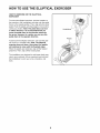
HOW TO USE THE ELLIPTICAL
EXERCISER
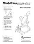
HOW TO EXERCISE ON THE ELLIPTICAL
EXERCISER
To mount the elliptical exerciser, hold the handles on
the console or the handlebars and step onto the pedal
that is in the lowest position. Then, step onto the other
pedal. Push the pedals until they begin to move with a
continuous motion. Note: The pedal discs can turn
in either direction. It is recommended that you
move the pedal discs in the direction shown by
the arrow; however, for variety, you can turn the
pedal discs in the opposite direction.
Handlebars
Pedals
To dismount the elliptical exerciser, wait until the pedals come to a complete stop. Note: The elliptical
exerciser does not have a free wheel; the pedals
will continue to move until the flywheel stops.
When the pedals are stationary, step off the highest
pedal first. Then, step off the lowest pedal.
The handlebars are designed to add upper-body exercise to your workouts. As you exercise, push and pull
the handlebars to work your arms, shoulders, and
back.
9
\
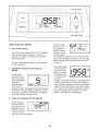
Increase Button
Decrease Button
HOW TO USE THE CONSOLE
The lower right
display can show
your pedaling
speed (in revolutions per minute)
and the approximate number of calories you have burned. When
you use the handgrip pulse sensor, the lower right
display will also show your heart rate (see step 4
on page 11).
I
1. Turn on the console,
ME HBsPEEol
Note: The console requires four 1.5V "D" batteries
(see assembly step 3 on page 6). If there is a
sheet of clear plastic on the face of the console,
peel off the plastic.
To turn on the console, press the increase button
or begin pedaling.
2.
Change the resistance
desired.
The upper display
is the priority display. The priority
display can show
the elapsed time,
the distance that
of the pedals as
As you pedal,
change the resistance of the pedals by pressing the
increase or
decrease button.
There are ten
resistance levels. The selected resistance level will
Follow your progress
.TJ.TJ
you have
pedaled, your pedaling speed, or the approximate
number of calories you have burned. Press the
Display button repeatedly until the priority display
shows the information that you are most interested in viewing. Note: While information is shown in
the priority display, the information will not be
shown in the lower left or right display.
be shown in the upper display. Note: After a button
is pressed, it will take a moment for the pedals to
reach the selected resistance level.
3.
! I
with the displays.
As you exercise,
the lower left display can show the
elapsed time and
the distance (total
number of revolutions) that you have pedaled.
10
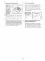
4.
Measure your heart rate if desired.
If there are
sheets of clear
plastic on the
metal contacts
on the hand-
5.
Turn on the fan if desired.
To turn on the fan at low speed, press the Fan
button. To turn on the fan at high speed, press
the button a second time. To turn off the fan,
press the button a third time. Note: If the fan is
left on and the pedals are not moved for thirty
seconds, the fan will automatically turn off to conserve the batteries.
Metal Contacts
grips, peel off
the plastic, To
use the handgrip
pulse sensor,
hold the hand-
Rotate the thumb
wheel on the right
side of the console to pivot the
fan to the desired
grips with your
palms resting against the metal contacts. Avoid
moving your hands, When your pulse is detected, the heart-shaped indicator in the lower right
display will flash each time your heart beats. After
a moment, your heart rate will be shown.
angle.
For the most accurate heart rate reading, continue to hold the handgrips for about 30 seconds.
Note: When you first hold the handgrips, the display will show your heart rate continuously for 30
seconds. The display will then show your heart
rate along with other feedback modes.
.
When you are finished exercising, the console will automatically turn off.
If the pedals are not moved for a few seconds,
the displays will pause and the priority display will
flash. If the pedals are not moved and the console buttons are not pressed for a few minutes,
the console will turn off to conserve the batteries.
11
MAINTENANCE
AND TROUBLESHOOTING
Inspect and tighten all parts of the elliptical exerciser
regularly. Replace any worn parts immediately.
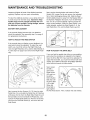
Next, see the drawing below and locate the Reed
Switch (53). Loosen, but do not remove, the indicated
M4 x 16mm Self-tapping Screw (52). Slide the Reed
Switch slightly toward or away from the Magnet (58) on
the flywheel. Retighten the Screw. Turn the left Pedal
Disc (15) for a moment. Repeat until the console displays correct feedback. When the Reed Switch is correctly adjusted, reattach the Side Shields (3, 4), the
right Pedal Disc (15), and the Right Pedal Leg (12).
To clean the elliptical exerciser, use a damp cloth and
a small amount of mild dish soap. Important: Keep
liquids away from the console and keep the console out of direct sunlight, During storage, remove
the batteries from the console.
BATTERY REPLACEMENT
If the console display becomes dim, the batteries
should be replaced. See assembly step 3 on page 6
for replacement instructions.
HOW TO ADJUST THE REED SWITCH
53
If the console does not display correct feedback, the
reed switch should be adjusted. To adjust the reed
switch, you must first remove the Right Pedal Leg
(12), the right Pedal Disc (15), and the Side Shields (3,
4). See step 8 on page 8 and remove the Right Pedal
Leg.
52
HOW TO ADJUST THE DRIVE BELT
If you can feel the pedals slip while you are pedaling,
even when the resistance is adjusted to the highest
level, the Drive Belt (19) may need to be adjusted. To
adjust the Drive Belt, you must first remove both side
shields. See HOW TO ADJUST THE REED SWITCH
at the left and remove the side shields.
15
Next, loosen
the M8 x
22mm Flat
\
Head Screw
(65) and turn
the M 10 x
60mm Button
Bolt (62) until
the Drive Belt
(19) is tight.
When the
62
19
Drive Belt is
tight, tighten
the Flat Head Screw. Then, reattach the side shields.
64
Next, remove the four Screws (51,70) from the right
Pedal Disc (15), and slide the Pedal Disc off. Remove
all Screws (52, 64) from the Right Side Shield (4) and
the two Bolts (41) from beneath the Pedal Disc, and
remove the Right Side Shield (4). Remove all Screws
(52) from the Left Side Shield (3), and move the Left
Side Shield.
12
EXERCISE GUIDELINES
Burning Fat--To burn fat effectively, you must exercise at a low intensity level for a sustained period of
time. During the first few minutes of exercise, your
body uses carbohydrate calories for energy. Only after
the first few minutes of exercise does your body begin
to use stored fat calories for energy. If your goal is to
burn fat, adjust the intensity of your exercise until your
heart rate is near the lowest number in your training
zone. For maximum fat burning, exercise with your
heart rate near the middle number in your training
zone.
te_
Aerobic Exercise--If your goal is to strengthen your
cardiovascular system, you must perform aerobic
exercise, which is activity that requires large amounts
of oxygen for prolonged periods of time. For aerobic
exercise, adjust the intensity of your exercise until
your heart rate is near the highest number in your
training zone.
These guidelines will help you to plan your exercise
program. For detailed exercise information, obtain a
reputable book or consult your physician. Remember,
proper nutrition and adequate rest are essential for
successful results.
WORKOUT
EXERCISE INTENSITY
Warming up--Start with 5 to 10 minutes of stretching
and light exercise. A warm-up increases your body
temperature, heart rate, and circulation in preparation
for exercise.
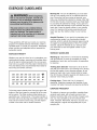
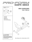
Whether your goal is to burn fat or to strengthen your
cardiovascular system, exercising at the proper intensity is the key to achieving results. You can use your
heart rate as a guide to find the proper intensity level.
The chart below shows recommended heart rates for
Training Zone Exercise--Exercise for 20 to 30 minutes with your heart rate in your training zone. (During
the first few weeks of your exercise program, do not
keep your heart rate in your training zone for longer
than 20 minutes.) Breathe regularly and deeply as you
exercise-never hold your breath.
fat burning and aerobic exercise.
165
155
145
140
130
125
_15
_
145
_38
_30
125
118
110
103
q,_?
_25
_20
115
110
]05
95
90
20
30
40
50
60
70
GUIDELINES
Cooling down--Finish
with 5 to 10 minutes of
stretching. Stretching increases the flexibility of your
muscles and helps to prevent post-exercise problems.
80
EXERCISE FREQUENCY
To find the proper intensity level, find your age at the
bottom of the chart (ages are rounded off to the nearest ten years). The three numbers listed above your
age define your "training zone." The lowest number is
the heart rate for fat burning, the middle number is the
heart rate for maximum fat burning, and the highest
number is the heart rate for aerobic exercise.
To maintain or improve your condition, complete three
workouts each week, with at least one day of rest
between workouts. After a few months of regular exercise, you may complete up to five workouts each
week, if desired. Remember, the key to success is to
make exercise a regular and enjoyable part of your
everyday life.
13
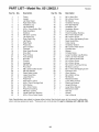
PART LIST--Model
Key No.
Qty.
1
2
3
4
5
6
7
8
9
10
11
12
13
14
15
16
17
18
19
20
21
22
23
24
25
26
27
28
29
30
31
32
33
34
35
36
37
38
39
40
1
1
1
1
2
1
2
1
2
2
1
1
1
1
2
2
1
1
1
2
2
1
1
2
2
1
4
4
1
2
2
1
7
4
4
2
2
5
2
2
No. 831.28622.1
Description
Frame
Upright
Left Side Shield
Right Side Shield
Handlebar Leg
Left Handlebar
MIO x 74mm Button Bolt
Right Handlebar
Stabilizer
M5 Nylon Locknut
Left Pedal Leg
Right Pedal Leg
Left Pedal
Right Pedal
Pedal Disc
Disc Crossbar
Flywheel
Side Shield Bracket
Drive Belt
Rear Endcap
Front Endcap
Belt Idler
Console
Handgrip
M6 Bolt Set
Pivot Axle
M8 x 52mm Button Screw
M8 Split Washer
Water Bottle Holder
Large Snap Ring
Large Bearing
Pedal Axle
MIO Nylon Locknut
MIO x 75mm Carriage Bolt
MIO Washer
M3 x 16mm Screw
Pedal Arm Bushing
M8 Nylon Locknut
Inside Pedal Arm Bushing
MIO x 27mm Patch Screw
Ro2o8A
Key No.
Qty.
41
42
43
44
45
46
47
48
49
50
51
52
53
54
55
56
57
58
59
60
61
62
63
64
65
66
67
68
69
70
71
72
73
74
75
76
77
*
*
*
2
6
4
2
2
2
2
2
6
4
4
7
1
1
2
2
1
1
4
4
2
1
2
4
1
2
2
1
2
4
4
1
1
2
1
2
1
-
Description
M6 x 18mm Bolt
M5 x16mm Screw
M5 Washer
Handlebar Endcap
MIO Split Washer
Handlebar Cap
Handlebar Spacer
Frame Spacer
Small Handlebar Bushing
M8 x 45mm Button Bolt
M6 x 25mm Screw
M4 x 16mm Self-tapping Screw
Reed Switch/Wire
Cable Clamp
Handlebar Washer
M8 x 25mm Patch Screw
Flywheel Axle
Magnet
Console Screw
Large Handlebar Leg Bushing
5/16" x 25.4mm Hex Bolt
MIO x 60mm Button Bolt
M4 x 22mm Screw
M4 x 25mm Screw
M8 x 22mm Flat Head Screw
M6 Nylon Locknut
M5 x 14mm Self-tapping Screw
Extension Wire
Wave Washer
M6 x 28mm Screw
M8 Washer
Resistance Motor
Lower Wire Harness
Pedal Leg Endcap
Upright Endcap
Large Wave Washer
Resistance Cable
Hex Key
Grease
User's Manual
Note: Specifications are subject to change without notice. See the back cover of this manual for information
about ordering replacement parts. *These parts are not illustrated. If a part is missing, call 1-888-533-1333.
14
EXPLODED DRAWING--Model
No. 831.28622.1
Ro2o8A
4
44
26
_p",,
41
I
59 48
_29
3
",
63
46
49 47
55
2
.--'"
64
..-"" 49
47
49
\\
_50
14
56
7 27_
77
25
34
21
51
13
73
11
15
20
76
® Registered Trademark / TMTrademark / SMService Mark of Sears Brands. LLC
® Marca Registrada / TMMarca de F a bnc a / SMM arca de Servicio de Sears Brands, LLC
f
90 DAY FULL WARRANTY
f
If this Sears Elliptical Exerciser fails due to a defect in material or workmanship within 90 days from the
date of purchase, call 1-800-4-MY-HOME ®(1-800-469-4663) to arrange for free repair (or replacement
if repair proves impossible).
This warranty does not apply when the Elliptical Exerciser is used commercially or for rental purposes.
This warranty gives you specific legal rights, and you may also have other rights which vary from state
to state.
Sears, Roebuck and Co., Hoffman
Estates,
IL 60179
J
J
Part No. 261865 R0208A
Printed in China © 2008 ICON IP, Inc.