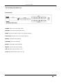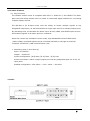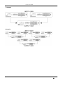
1
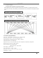
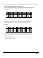
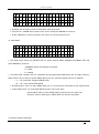
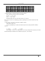
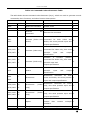
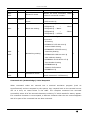
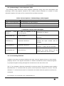
Owner´s Manual MX - 800 8 x 8 Digital Modular Matrix Router PureLink GmbH Table of Contents 1. Product Overview Page. 1.1 Safety Precautions 3 1.2 Introduction 4 1.3 Part Names & Reference 5 1.4 Installation 7 2. Product Features 2.1 Key Functions 8 2.2 Features & Specifications 10 3. Operational Guidelines 3.1 “MAIN MENU” User Guide 11 4. Communication Code Configuration 4.1 RS-232C(COM) COMMUNICATION CODE SET-UP 16 4.2 LAN(TCP/IP) COMMUNICATION CODE SET-UP 24 4.3 Connector Pin Assignment 26 5. Additional Information 5.1 Warranty 27 2 PureLink GmbH 1. Product Overview 1.1 Safety Precautions - Always use the correct external power supply (indicated on the product label) when operating this unit. - Please refrain from using frayed power cords and damaged wall outlets. - Mishandling of this product may lead to a fire or explosion hazard. - Do not place any heavy objects or equipment on top of the unit. - Keep away from wet, magnetic, and flammable surfaces or substances. - Air vents should be kept clean and unobstructed at all times. - Any external impact may cause damage to the operation of this unit. - Be sure this unit is properly grounded (earthed) in order to prevent the risk of electrical shock. - Please contact our technical support team at any time for assistance with the usermanual, installation, or operation of this unit. 3 PureLink GmbH 1.2 Introduction The MX-800 matrix router supports DVI 1.0, HDMI Ver1.3, and HDSDI interface settings in a single unit. The modular input/output ports allow users to connect multiple displays to the router. The MX-800 features a switching mechanism that splits signals from 8 channels to any designated output port. Through channel-input configuration, the MX-800 can recognize up to 32 DVI, HDMI, and HDSDI signals and send them to 8 output ports on command. DVI 1.0 and HDMI Ver. 1.3 matrix transmits advanced video and audio signals 19“ Standard RACK TYPE CASE(2U) Router-to-router cascading (up to 3 levels) Supports EDID-Save functionality. The unit will detect the output source’s EDID and record it in the unit. PRESET feature allows users to program up to 16 channels Compliant with HDCP (High-bandwidth Digital Content Protection) using DVI and HDMI standards Supports high-bandwidth digital signals Other Specifications: 1. Up to 1920 x 1200 (WUXGA) resolution, 480i/p ~1080i/p video 2. Designed to support 5 slot-types depending on desired use: DVI / DVI&3.5 / STEREO / HDSDI / CAT-5 / OPTICAL 3. With the ability to cascade units, up to 32 computer or A/V sources can be connected to 8 display sources. 4. The LCD display window allows users to easily view the current operational mode of the router. 4. Output ports can be designated using four convenient methods based on user-preference: - Manual input through KEY SWITCH in the front panel - RS-232C configuration - LAN (TCP/IP) configuration 5. Integrated noise-cancellation and error-correction logic for both input and output ports to prevent any damage caused by electrical noise. What’s Included: - MX-800 main frame and card slots Power adapter (DC12V , 6.6A/ 80Watt) RS232C & LAN Cable User Manual 4 PureLink GmbH 1.3 Part Names & Reference Front Panel: POWER: Main power switch ON / OFF DISPLAY: View menu and system mode RESET: Revert the matrix router to its original settings. FUNCTION: Navigate menu and control options CREATE: Program input channels PREVIEW: View saved channel ENTER: Save/select desired setting CANCEL: Revert to previous setting IN1~8: Select input channels (1~8) OUT1~8: Select output channels (1~8) 5 PureLink GmbH Back Panel DC 12V: Power supply (DC +12V) input port LAN: LAN (TCP/IP) input port RS-232 C: RS-232C input port INPUT SLOT : DVI , DVI&3.5 STEREO , HDSDI , CAT-5 , OPTICAL ports (IN1~8) OUTPUT SLOT : DVI , DVI&3.5 STEREO , HDSDI , CAT-5 , OPTICAL ports (OUT1~4)x2 EA 6 PureLink GmbH 1.4 Installation Guidelines and Procedures 1. Installation Environment The following settings are recommended in order to achieve optimal performance: - Operational temperature should be 30° C (best condition) or below - Operational humidity should be 60% (best condition) or below - Operational space should be dust-free and well ventilated - AC power supply safety (AVR-based power supply is highly advised) 7 PureLink GmbH 2. Product Features 2-1. Key Functions The MX-800 matrix router is compliant with DVI 1.0, HDMI V1.3, and HDSDI. The backpane card slot design allows users to create a customized digital interface for connecting multiple display sources. The MX-800 is an 8-input router with the ability to switch multiple signals to any designated output port, as well as distribute a single input source to multiple output ports. By cascading units, the MX-800 can detect up to 32 DVI, HDMI, and HDSDI input sources and transmit signals to 8 output ports on command. When the routers are cascaded in three levels, high-bandwidth DVI and HDMI video (1920*1080p) command signals can be controlled manually or through an external computer via RS232C / LAN communication code. 1. Cascading Units (3-level Set-up) Input: 32-Channel Output: 8-Channel In/Out Configuration: [8 8]*4set, [8 :8]*2set , [8 8]*1set In/Out Connection: match a single output port with any designated port out of the 32 input ports Enabled configuration: 32in-32out -> 16in -16out -> 8in-8out 1-Level: 8 PureLink GmbH 2-Levels: 3-Levels: 9 PureLink GmbH 2. System Diagram The figure below illustrates a connectivity diagram. Input signals can be switched manually through the front panel or through external control sources (IR, RS-232C, LAN (TCP/IP)), and distributed to any combination of designated output ports. DVI MATRIX ROUTER BLOCK DIAGRAM DVI MATRIX ROUTER INPUT/OUTPUT CONFIGURATION 2-2 Features & Specifications Signal Type : TMDS SIGNAL , DIGITAL R.G.B. & DIGITAL AUDIO Data Transmission Speed : UP TO 2.25 Gbps(Single Link) Highest Resolution: WUXGA(1920*1200) , 480i/p ~ 1080 i/p LCD Display Window: 20*4 LINES LCD Output Port Set-up: Front panel SWITCH, RS-232C configuration, LAN(TCP/IP) configuration Input Port Set-up: input *8 / output *4x2 EA Source Connection: DVI-D 29pin Female HDMI 19pin Female , BNC Female Power Supply : DC12V , 6.6A Power Consumption : 25 Watt / 35Watt Dimensions ( W x D x H, inch ) : 17.1’ x 8.6’ x 3.5’ (2U) Total Weight: 9.15 Lbs 10 PureLink GmbH 3. Operational Guidelines 3.1 MAIN MENU User Guide Turn the power switch on Once all channel indicator lights are on, the first step is complete 1. Initial page on the LCD display 2. Channel View and Input Selection IN / OUT indicates connection status Press the IN / OUT KEY to display each channel’s connection status and video resolution Press the CANCEL KEY to return to the initial screen 3. MX-800 MAIN MENU 1 . C R E A T E 2 . P R E S E T 3 . P R O D U C 4 . R S 2 3 2 T _ I D Press the FUNCTION KEY to view the menu screen Use the CREATE(UP) / PREVIEW(DOWN) KEYS to control the menu options 1. CREATE 2. PRESET 3. PRODUCT_ID 4. RS232 5. LAN 11 PureLink GmbH 6. SYSTEM INFO 7. EDID 8. SYSTEM CONFIG Press the ENTER KEY to select an option. Press the CANCLE KEY to return to the main menu 4. CREATE MENU - P I N / O r e s s u t A C n R y E A T E I n p u - T Select an INPUT channel Press the IN / OUT KEY to set a channel Press the ENTER KEY to save or switch input channels Press CANCEL to reverse a selection and return to the previous screen 5. PRESET MENU - P R E S E T - 1 . P R E S E T C a l l 2 . P R E S E T E d i t PRESET Call : Establish IN/OUT channels PRESET Edit: Edit and save up to 20 IN/OUT channels Use the CREATE(UP) / PREVIEW(DOWN) KEYS to select desired menu option Use the UP / DOWN / IN / OUT KEYS to edit and press ENTER to save or execute Press the CANCEL KEY to reverse current settings and return to the previous screen 6. PRODUCT ID MENU - P : S e t E d i t R O D U C T I D - 1 : 12 PureLink GmbH Create up to 20 PRODUCT ID’s Set : Displays current number or PRODUCT ID’s Edit : Use the UP / DOWN KEY to select the ID and press ENTER to edit or save. Press CANCEL to reverse selection and return to the previous screen 7. RS232 MENU B a u d R a t e : D a t a B I t s : S t o p B I t s : P a r i t y : Select RS232 FUNCTION to view the current RS232 set-up Use the UP / DOWN KEY to make a selection and press ENTER to continue Use the UP / DOWN KEY to select desired setting and press ENTER to save Press CANCEL to reverse selection and return to the previous screen 8. LAN MENU - L a n P A d d r y 1 . I 2 . G a t e w a 3 . S b n e t u E d i t e s S A d d M a s k - r e s S Use the UP / DOWN KEY to select from MENU and press ENTER to continue. Use the IN / OUT KEY to change desired codes and press ENTER to save KEY NUMER Assignment IN1( 1 ) , IN2( 2 ) , IN3( 3 ), IN4( 4 ), IN5( 5 ), IN6( 6 ), IN7( 7 ) , IN8 (8) OUT1(9) , OUT2(0) , OUT3(.) Press the OUT3(.) KEY to reassign numbers Press CANCEL to reverse changes and return to the previous screen 9. SYSTEM INFO FUNCTION 13 PureLink GmbH 1 . M a i n S l o T 2 . I n p u S l o t 3 . O u t 1 S l o T ( 1 ~ 4 ) 4 . O u t 2 S l o T ( 5 ~ 8 ) t Displays the firmware version associated with each SLOT. Use the UP / DOWN KEY to select from menu and press ENTER to continue. Press CANCEL to reverse selection and return to the previous screen. 10. EDID MENU 1 . E x t E d i d L o a d 2 . I n t E d i d L o a d 3 . E x t E d i d S a v e 4 . I n p E d C h u t i d e C k Ext Edid Load: Press the OUTPUT KEY to select desired EDID SOURCE and INPUT KEY and press ENTER to continue. : LOADING status will appear as follows: F FAIL P PASS Int Edid Load: MX-800 has 14 selectable pre-programmed EDID data and 6 empty memory spaces that can be used to upload EDID data from any external display device in advance. 1 ~ 14: Internally assigned EDID DATA 15 ~ 20: User-saved EDID DATA Ext Edid Save: User can save EDID DATA for 15~20 monitors connected to the output ports Input Edid Check: To view EDID DATA saved in the input slots : Press INPUT KEY to check EDID DATA coming from the input port : #Notice: When checking for EDID DATA the screen may flash 9. SYSTEM CONFIG FUNCTION 14 PureLink GmbH - S Y S T E M h i S 1 . S w i t c 2 . I n u t p C O N F I G n g D e l a e l c t e Y Switching Delay: controlling channel conversion speed Fast: quickest conversion (DVI or 2CH HDMI) Normal: 2-3 sec. delay Slow: 3-5 sec. delay Switching delay may vary with each monitor or TV source. If the video or audio is not displaying properly, adjusting the conversion speed may help correct it. Input Select: choosing the input port. (HDMI or CAT5) HDMI INPUT SLOT only Use the UP/DOWN Key to select the desired input source and press ENT or MEN to continue. H : HDMI , C : CAT5 , A : AUTO AUTO MODE : If there is no VIDEO DATA in the newly configured the input port, the data will automatically be transferred to a different input port. (3-5 seconds) 15 PureLink GmbH 4. Communication Code Configuration 4-1.COMMAND LINE OPERATIONS ■ Control Programmer’s Guide (Code Structure and Examples) This section is designed for programmers who wish to create their own control programs using the command code. All Pure Link digital matrix routers provide a simple character stream control used by external control devices attached to a Pure Link device. Command codes are used primarily for control, during system installation and setup, and for diagnostic purposes. Overview Command code is a set of alphanumeric characters that combine to form control commands. Command code strings are entered into a terminal emulation program (such as windows HyperTerminal) running on an external control device. The control device (PC, third-party controller) sends the commands to the system. Control devices must be able to send and receive ASCII or HEXA code via an RS-232 or Ethernet port. Command Code Formats A command code is a series of command characters and numbers used to send commands to the system. Commands include basic formulas for creating and disconnecting switches, as well as for verifying the status of switches. In a command code, each character is either general command (e.g, C for connect) or an identifier that indicates what the following number designates (e.g, “O” and the number following it designate an “output number”). The command code *255CI01O01! Can be interested as follows: (*) Starting the command code (255) Router ID is 255 (C) Create connection on (I01) Input 01 to (O01) Output 01 (!) take the command. For a complete list of command characters and their functions, see pages 17-24 Ack value (Acknowledge value: Response from Pure Link device) will be echoed back to the terminal screen as the unit accepts them. When a command is successfully executed, all of the characters appear containing the character “s” which stands for status. For example, 16 PureLink GmbH Ex 1) Command (Connect Input 1 to Output 1) *255CI01O01! ¶ Ack value *255sC I01O01! Ex 2) Command (Check Input connection status on Output 3) *255?O03! ¶ Ack Value *255s? I03O03! General Rules for Command Codes The commands are coded in ASCII and HEXA. Please refer to Table 3.1 on pg. 18 for detailed descriptions of keys and functions. A basic command code setup is shown below; Ex) *255CI01O01! ¶ Start (*) + Router ID (255) + Command (C) + Input number (I01) + Output number (O01) + End (!) + Enter (¶ ) ▶ A command line allows execution of only one command. Multiple commands require execution of multiple strings; one command per string. ▶ All s begin with * (Start) byte. ▶ All s end with ! (End) byte. ▶ All s will be executed when ¶ (Enter) is entered. ▶ The correct Router ID must be entered in a command code. Systems will not react to the command if a wrong Router ID is entered. The Factory Default Router ID is set to 255 and the universal Router ID is 999. Systems will react to the command whenever universal Router ID is entered in command code. ▶ Command codes typically are not case-sensitive. ▶ To specify multiple inputs and outputs, enter a “,” (Comma) between numbers. (Ex., *255CI01O01,02,03! ¶ : Connects Input 01 to Output 01, 02, and 03) ▶ Use - (Hyphen) for range connection. (EX., *255CI01O01-04! ¶ : Connects Input 01 to Output 01,02,03, and 04) 17 PureLink GmbH Table 3.1 Command Codes Characters Table The table below shows command code characters (keys), which are used to generate control commands, their functions, and short function descriptions. Key Function Description and Example Byte HEX ASCII 0x2A * Start the command Header Code 1 0x21 ! End the command Tail Code 1 ¶ Execute the command Execute the command Initiates a Connect for both (switch) 0x43 C Connect (Video and command Video and 0x63 c Audio) Audio; this must precede input and 1 output specification Initiates 0x56,0x43 VC 0x76,0x63 vc Connect (Video only) a Connect (switch) command for Video only; this must precede input and output 2 specification Initiates 0x41,0x43 AC 0x61,0x63 ac Connect (Audio only) a Connect (switch) command for Audio only; this must precede input and 2 output specification Status 0x3F ? Status command; precede input this must and output 1 specification Disconnect 0x44 D 0x64 d 0x56,0x44 VD Disconnect 0x76,0x64 vd only) 0x41,0x44 AD Disconnect 0x61,0x64 ad only) Disconnect for both Video and Audio; this must precede 1 input and output specification (Video Disconnect Space command for Video only; this must precede input and 2 output specification (Audio Disconnect command for Audio only; this must precede input and 2 output specification Separates , command entries the that numbers contain within multiple 1 Specifies a range of numbers in 1 numbers - Range 18 PureLink GmbH entries containing multiple numbers 0x49 I 0x69 i ?version Router ID check command; check Router ID check Firmware router’s current ID number version check 1 Firmware version check command; *255?version! ¶ Baud rate sting command; *255@001!¶ 0x40 @ Baud rate setting 19200 → *255@002!¶ → 38400 *255@003!¶ 57600 → *255@004!¶ → 115200 Network configuration setting command: - IP Setting *255NIP125.135.199.004! ¶ - Subnet Mask Setting *255NSM255.255.255.000! ¶ 0x4E N 0x6E n Networking setting - Gate Way Setting *255NGW192.168.000.001! ¶ 1 - MAC Address Setting *255NMA00.50.C2.B0.20.05! ¶ - Port Number Setting *255NPN3000! ¶ - Network Information *255NNI000! ¶ 0x48 H 0x68 h Connection check Router communication connection check command: *255H000! ¶ 1 Command Ack (Acknowledge) Value Response When command codes are entered into a terminal emulation program (such as HyperTerminal) and are accepted by the system, they respond back to the terminal screen one at a time, as noted below in the table. The complete command has executed successfully when all of the entered characters including “s” which stands for status, appear. If a command character is not accepted, a different character than the one entered appears and all or part of the command has not been executed. 19 PureLink GmbH Ack (Acknowledge) Value Response Table The following table shows ack value response characters along with their descriptions and meanings, which may appear instead of the initially entered character or number. If these characters appear, all or part of the command has not been executed. Table 3.2 Descriptions of Acknowledge (ACK) Signals Ack value Description Input 1 is not connected No information in each channel. Command Code Error Indicates that system has rejected all or part of the command Router ID Error Indicates that the wrong ID number was entered Command Code Ack Value Examples Command Code Ack Value as appears in the Entered control program *255CI01O01! ¶ *255sC I01O01 ! Explanation of Result The Command Code Error was successfully executed The *255CO01! ¶ command command was not executed because the input number was not included *255CI01O01 ¶ Command Code Error The Router ID Error was not executed because “!” (End) was not included The *300CI01O01! ¶ command command was not executed because the actual Router ID and entered Router ID did not match 4-1.1 Connecting Switches A switch is an active connection between an input (source) signal and one or more output (display) devices. The signals connected in a switch command are either individual signals or groups of signals coming through the connectors on the rear of the unit. The “C” key initiates a Connect command for routing a switch. The characters and numbers that follow the “C” command tell the system, which inputs and outputs to connect. The last character “!” is found at the end of a command code which tells the system to execute the command. For example, the command code *255CI01O01! ¶ 20 PureLink GmbH can be interpreted as follows: (*) Starting the command code (255) Router ID is 255 (C) Create connection on (I01) Input 01 to (O01) Output 01 (!) take the command. For a complete list of command characters and their functions, see examples below. To connect a switch: 1. Enter the Connect command below. Replace the “#”s with the input and output number(s). *255CI#O#! ¶ Examples (Connect Video and Audio): Command Codes Action *255CI01O01! ¶ Connect Input 1 to Output 1 *255CI01O08,I08O02! ¶ Connect Input 1 to Output 8 and Input 8 to Output 2 *255CI01O01,I02O02,I03O03! ¶ Connect Input 1 to Output 1, Input 2 to Output 2, and Input 3 to Output 3 *255CI01O01,02,03! ¶ Connect Input 1 to Output 1, 2, and 3 *255CI01O01-07! ¶ Connect Input 1 to Output 1, 2, 3, 4, 5, 6, and 7 Examples (Connect Video only): Command Codes Action *255VCI01O01! ¶ Connect Input 1 to Output 1 *255VCI01O08,I08O02! ¶ Connect Input 1 to Output 8 and Input 8 to Output 2 *255VCI01O01,I02O02,I03O03! ¶ Connect Input 1 to Output 1, Input 2 to Output 2, and Input 3 to Output 3 *255VCI01O01,02,03! ¶ Connect Input 1 to Output 1, 2, and 3 *255VCI01O01-07! ¶ Connect Input 1 to Output 1, 2, 3, 4, 5, 6, and 7 Examples (Connect Audio only): Command Codes Action *255ACI01O01! ¶ Connect Input 1 to Output 1 *255ACI01O08,I08O02! ¶ Connect Input 1 to Output 8 and Input 8 to Output 2 *255ACI01O01,I02O02,I03O03! ¶ Connect Input 1 to Output 1, Input 2 to Output 2, and Input 3 to Output 3 *255ACI01O01,02,03! ¶ Connect Input 1 to Output 1, 2, and 3 *255ACI01O01-07! ¶ Connect Input 1 to Output 1, 2, 3, 4, 5, 6, and 7 21 PureLink GmbH 4-1.2 Disconnecting Switches The characters and numbers in a Disconnect command tell the system which input or output to disconnect. The “D” key initiates a Disconnect command for routing a switch. The characters and numbers that follow the “D” command tell the system that inputs and outputs to disconnect. The last character “!” is found at the end of the Command code, which tells the system to execute the command. For example, the command code *255DI01O00! ¶ It can be interpreted as follows: (*) Starting the command code (255) Router ID is 255 (D) Disconnect on (I01) Input 01 to (O00) Output 00 (!) take the command. For a complete list of command characters and their functions, see the command list below 1. Enter the Disconnect command below. Replace the “#”s with the input and output number(s). *255DI#O#! ¶ Examples (Disconnect Video and Audio): Command Codes Action *255DI01O00! ¶ Disconnect Input 1 to no Output (00) *255DI00O03,04,05! ¶ Disconnects Outputs 3, 4, and 5 *255DI00O03-06! ¶ Disconnects output 3, 4, 5, and 6 *255DALLIO! ¶ Disconnects all inputs and outputs Examples(Disconnect Video only): Command Codes Action *255VDI01O00! ¶ Disconnect Input 1 to no Output (00) *255VDI00O03,04,05! ¶ Disconnects Outputs 3, 4, and 5 *255VDI00O03-06! ¶ Disconnects output 3, 4, 5, and 6 *255VDALLIO! ¶ Disconnects all inputs and outputs Examples(Disconnect Audio only): Command Codes Action *255ADI01O00! ¶ Disconnect Input 1 to no Output (00) *255ADI00O03,04,05! ¶ Disconnects Outputs 3, 4, and 5 *255ADI00O03-06! ¶ Disconnects output 3, 4, 5, and 6 *255ADALLIO! ¶ Disconnects all inputs and outputs 22 PureLink GmbH 4-1.3 Connection Status Check A connection status can be checked to confirm that the switch has been correctly executed or to confirm correct routing to multiple outputs. The characters and numbers in a status command tell the system which input or output to check. 1. Enter the Connection status check command below. Replace the “#”s with the input and output number(s). *255?I#!¶ or *255?O#! ¶ Examples: Command Codes Action *255?I01! ¶ Check Output connection status on Input 1 *255?O07! ¶ Check Input connection status on Output 7 *255?ALLIO! ¶ Check all Input and Output connection status 4-1.4 Router ID Check User can confirm the router’s Current ID setting. ● Universal Router ID is 999 Example: Command Codes Action *999I000! ¶ Check Router’s ID 4-1.5 Firmware Version Check User can confirm router’s current firmware version. Example: Command Codes Action *999?version! ¶ Check Router’s Firmware version 23 PureLink GmbH 4-1.6 Baud Rate Setting User can set baud rate for RS-232 command control. 1. Enter the Baud rate setting command below. Replace the “#”s with the input and output number(s). *255@#! ¶ @001: Baud rate at 19200 @002: Baud rate at 38400 @003: Baud rate at 57600 @004: Baud rate at 115200 Example: Command Codes Action *255@001! ¶ Set baud rate at 19200 *255@002! ¶ Set baud rate at 38400 *255@003! ¶ Set baud rate at 57600 *255@004! ¶ Set baud rate at 115200 Network Configuration: User can check and set network configuration for LAN control. Examples: Command Codes Action *255NNI000! ¶ Check current Network Information *255NIP192.168.000.004! ¶ Set IP address at 125.135.199.004 *255NSM255.255.255.000! ¶ Set Subnet Mask at 255.255.255.000 *255NGW192.168.000.001! ¶ Set Gate Way at 192.168.000.001 *255NMA00.00.C2.B0.20.05! ¶ Set Mac Address at 00.00.C2.B0.20.05 *255NPN3000! ¶ Set Port Number at 3000 Connection Checking: User can check the connection status. Example: Command Codes Action *255H000! ¶ Check connection status 24 PureLink GmbH Function Key On/Off: User can enable or disable the function key located on physical router’s front panel. Example: Command Codes Action *255K000! ¶ Function key On/Off 4-2 LAN CODE CONFIGURATION 4-2.1 Using TELNET protocol with LAN(TCP/IP) The MX-800 router can be controlled from remote locations through the LAN port using WINDOWS XP DOS prompts, hyper-terminal, or TELNET program (the control code is fully compliant with RS-232C). Enter TELNET <Router IP Address> in the DOS prompt Message indicating TELNET connection will appear 25 PureLink GmbH *255I000! *255sI Router ID 255* Router ID verification command code Send “ *255I000! ” Router will send response: “ *255sI Router ID 255” 4-2.2 Using HTTP protocol with LAN(TCP/IP - Control PC Search Searching data for channel configuration Character train should begin with “LCD.CGI” to “O01=I08” to Output 01 = Input 8. The sequence and size of the character train must be the same. To RESET the protocol, a new connection to the server (Switcher) must be established. Switching Channels http://192.168.0.2/LCD.CGI?O01=I01&O02=I02&O03=I03&O04=I04&O05=I05&O06=I06 &O07=I07&O08=I08&Submit_=SEND RESET http://192.168.0.2/LCD.CGI?O01=I01&O02=I02&O03=I03&O04=I04&O05=I05&O06=I06 &O07=I07&O08=I08&Submit_=RESET - Control PC Transmission Information from each channel that needs to be sent must be extracted to prevent the entire Explore html data from being transmitted. - 8:8 html transmitting 26 PureLink GmbH Run Explorer and enter the newly configured IP address to open the channel configuration window above. Select desired channel and click SEND to change the channel. 27 PureLink GmbH 4-3 Connector Pin Assignment Power Input Part Name Power Jack RS-232C Input Part Name D-SUB 9-Pin Connector LAN Connector Part Name RJ-45 8-Pin Connector Pin 1 2 3 4 Description VCC( DC12V) VCC(DC12V) GND GND Remarks Pin 1 2 3 4 5 6 7 8 9 Description Not used Rx D Tx D Not used GND Not used Not used Not used Not used Remarks Pin 1 2 3 4 5 6 7 8 Description Transmit data (+) Transmit data (-) Receive data(+) Not used Not used Receive data(-) Not used Not used Remarks 28 PureLink GmbH 5. Additional Information Manufacturer’s Warranty (2-Year) Dtrovision warrants this MX-800 modular matrix router to be free from defects in workmanship and materials, under normal use and service, for a period of two (2) year from the date of purchase from Dtrovision or its authorized resellers. If the product does not operate as warranted during the applicable warranty period, Dtrovision shall, at its option and expense, execute one of the following as necessary: 1. Repair the defective product or part 2. Deliver to customer and equivalent product or part to replace the defective item 3. Refund to customer the purchase price paid for the defective product All products that are replaced become the property of Dtrovision, LLC. Replacement products may be new or reconditioned. Repaired or replacement products or parts come with a 90-day warranty or the remainder of the warranty period. Dtrovision shall not be responsible for any software, firmware, information, or memory data loss of contained in, stored on, or integrated with any products returned to Dtrovision for repair under warranty. Customer Service Any customer service inquiries can be submitted electronically through the Q&A form on our website (www.purelinkav.com). For immediate assistance please contact us at (201) 488-3232 to reach our customer care or tech support team. 29 PureLink GmbH Hovesaatstraße 6 D-48432 Rheine Telefon: +49 (0) 5971 800 299-0 Fax: +49 (0) 5971 800 299-99 E-mail: [email protected] www.purelink.de For order support, please contact your local dealer. For technical support, please contact us at [email protected]