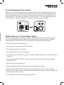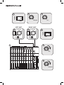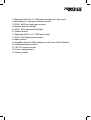
1
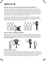
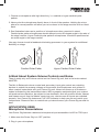
OWNER’S MANUAL
Thank you for purchasing this Rockville Power Gig series pro audio speaker.
We are very proud to bring you what we consider to be the absolute best value line pro
audio speakers. This project has been a culmination of years of development involving
a team of dreamers, engineers, designers and marketing gurus. Proudly conceived and
developed in the USA, Rockville pro audio speakers are designed and engineered by a
team of music enthusiasts, DJ’s and musicians.
We have spared no expense in manufacturing these speakers to meet the highest quality
standards. With proper care and installation this unit will provide you with the highest
levels of sound quality. We hope that this unit will bring you years of performance and
reliability.
Our goal to you and to your audience is to hear “live performance sound” the way it was
meant to be experienced.
Please read this installation guide carefully for proper use of your Power Gig series pro
audio speaker. Should you need technical assistance during or after your installation
please call our technical help line at 1-646-758-0144, Monday through Friday, 9am to
5pm EST.
Features
•
•
•
•
•
•
•
•
•
•
•
•
•
•
•
•
•
•
High-power 2-way pro sound reinforcement speaker system for live sound and
playback applications
Compact and light weight system delivers distortion free sound even at extreme SPL
Linear Class AB amplifier technology: high power, transparent sonic performance
Internal switch-mode power supply for low distortion audio with superior transient
Built-in bass and treble equalization processor for ultimate system control and
speaker protection
State-of-the-art Japanese made pure titanium-diaphragm compression driver
for crystal clear high-frequency reproduction
Ultra-wide dispersion, 40° large-format horizontal wave guide horn molded directly
into cabinet
Ultra-low noise Mic / Line input via XLR & 1/4" TRS jack with volume control
Line RCA and XLR input with separate Gain adjustment
Balanced line output via XLR & 1/4" TRS jack for linking of additional
speaker systems
Versatile trapezoidal enclosure design allows different positioning
Flyable and stand mounting with 35-mm pole socket
Tilts on its side for use as a floor monitor with included brackets
Ergonomically shaped handle for easy carrying and setup
High-quality components and exceptionally rugged high impact ABS construction
Amplifier clip limit LED indicator & power LED cabinet rear
Front display power meter Blue LED
115 / 230 Volt switchable power supply with external user serviceable fusing
IMPORTANT SAFETY INSTRUCTIONS
RISK OF ELECTRIC SHOCK
DO NOT OPEN
•
•
•
•
response
To reduce risk of electric shock, never open the unit. There are no user serviceable
parts, refer service to an authorized Rockville service center.
Do not expose this unit to any kind of moisture.
Please ensure that the unit is situated in a properly ventilated area.
Make sure the unit is placed on a level and stable surface.
Setting Up Your Power Gig Professional Sound System
Your Power Gig is set up to produce the full spectrum of sound from its woofer and
tweeter horn combination. The lower frequencies seek out the floor of the room they are
playing and travel along the floor and walls. The tweeter horn is more directional. Hence
when setting up your system its more important to make sure that the tweeter horns are
not blocked by any furniture and are located / aimed at ear level to the listening audience.
Woofer aiming is not as critical as explained previously due to the nature of the woofer
sounds able to travel through various paths even when blocked.
It is therefore recommended that when setting up your system you set up your speakers on speaker stands, such as the Rockville model RVSS-2 (not included) so that the
tweeter sounds will radiate above the listening crowd. This will guarantee optimum sound
dispersion and achieve clear vocal sound reproduction.
How To Avoid Irritating Feedback
The placement of your microphone is critical in avoiding feedback through your Power
Gig system. Never set up your microphone in front of the speaker. Always set up your microphone behind the speaker. When approaching the speaker to make any adjustments,
we recommend approaching the speaker from the rear and not walking directly towards
the front of the speaker.
Stage Monitor Setup
Your Power Gig speaker comes standard with two brackets which snap in to the cabinet
sides allowing it to be placed on the floor at an angle as a stage monitor. Unlike a PA setup which face the crowd, stage monitors are set up to face the performer on stage and to
direct the sound towards them. This presents a particular problem as now feed back may
occur. To avoid stage monitor feedback the following precautions should be taken.
e.
d
-
o
y
1. Choose a microphone with high directivity, i.e. cardioid or hyper-cardioid polar pattern.
2. Never point the microphone directly down in front of the speaker. Holding the micro
phone in normal position will allow you to be closer to the stage monitor with out feed back.
3. See illustration below as to position of microphones when mounted in stand.
Cardiod polar patter microphones should always be at a 90 degree angle to the axis of the stage monitor. Hyper Cardioid polar pattern microphones should be positioned at an acute angle to the sage monitor.
You may choose to add a feedback eliminating processor to your system for additional
flexibility on stage.
Cardiod Polar Patter
Hyper Cardiod Polar Patter
A Word About System Volume Controls and Gains.
There is really only one volume control on the Power Gig unit, that is the knob marked
MASTER.
The Mic In Balanced volume control and secondary input gain control are matching
devices to match the preamp voltages of items such as microphones and guitars or
other musical instruments with your Power Gig unit. Never turn these up to maximum
unless indicated by the instructions below. With a properly matched signal your system
will produce less distortion, be subject to less feedback, and will produce louder, cleaner
and clearer sound. Use the Master control as your volume once all inputs are matched
properly. Your Power Gig features a CLIP LED indicator to help you set and match your
components. Please be sure to read all set up instructions so your Power Gig sounds its
best.
APPLICATION USES
Microphone Presentations
Your Power Gig features a balanced microphone input accessible via XLR or TRS input.
1. Make sure the Power Gig is in OFF position.
2. Plug in your microphone.
3. Keep Master Volume at 0 position.
4. Turn Mic Volume to 0 position.
5. Switch on the Power Gig unit.
6. Slowly turn microphone volume in clockwise rotation until you achieve appropriate gain
setting. This is determined by the CLIP LED indicator light. Proper function is achieved when the CLIP indicator lights up at peak levels, it should never be in constant on position.
7. The above adjustment matched the microphone preamp to the input gain of the Power Gig unit.
8. Now turn up the Master Volume to necessary volume by rotating clockwise.
Always stand behind the Power Gig when making your microphone adjustments to avoid
feedback distortion.
2
POWER
1
4
3
MIC IN BAL
0
OFF
6
POWER
5
0
ON
MASTER
6
POWER
10
VO L
10
VO L
0
10
8
CLIP
0
10
MASTER
Multi-Microphone Hook Up
You can choose to hook up two microphones to your Power Gig in the following manner.
Set up Microphone #1 as instructed above. Using same set up instructions, insert microphone #2 into second XLR balanced input which features its own separate gain control.
This second XLR though balanced is part of the Line In circuit and thus will have a -10dB
response and will be lower in volume than microphone #1. Use the gain control associated with this input to increase the microphone level and balance the inputs between the
two microphones before attempting to adjust the Master Volume.
LINE IN
R
L
0
BAL
10
GAI N
0
10
MASTER
n
d
.
Line Out Balanced Connection.
The XLR / 1/4" TRS jack marked Line Out Bal allows for daisy chaining of signals from
one Power Gig unit to another. Simply attach an XLR or 1/4" to RCA cable between the
two units to share signals. The input into Power Gig #2 should go to the LINE IN XLR or
RCA BAL input. You can even choose to use Power Gig # 1 for microphone inputs and
Power Gig #2 for musical instrument inputs and mix the two units together.
LINE IN
R
L
BAL
Public Address / Concert Mixer Setup
When setting up for larger venues, a mixing console becomes a critical piece of equipment for appropriately mixing signals from multiple inputs such as singers, speakers,
effects devices, musicians and of course allows for multiple speaker utilization.
To connect a mixing console begin by.
1. Turning your Power Gig unit to OFF position.
2. Turn Master Volume to 0 position.
3. Turn MIC IN BAL Volume to 0 position.
4. Connect the LEFT OUTPUT of mixer to the MIC IN BAL connection of your Left Power Gig Unit.
-
5. Connect the RIGHT OUTPUT of mixer to the MIC IN BAL connection of your Right Power Gig Unit.
B
6. Switch ON your Power Gig unit.
7. Slowly raise the level of the mixer output to the 0dB level position.
8. Slowly turn the MIC IN BAL volume control clockwise until the CLIP LED indicator begins to blink, then turn it down slightly. This indicates the maximum input voltage gain
is matched and set properly.
9. Turn Master Volume up to achieve proper volume.
3
2
POWER
1
OFF
LEFT UNIT
MIC IN BAL
10
VO L
0
10
MASTER
RIGHT UNIT
5
MIC IN BAL
6
POWER
4
0
7
ON
8
0
10
VO L
9
0
MASTER
Line Input Feature
You can use the Line Input function when you wish to hook up an additional stereo signal
source without the use of a mixer console. CD players, DVD music players, MP3 players
etc can be plugged directly in to the RCA jacks labeled LINE INPUT.
To connect a CD, DVD music player or MP3 player.
1. Turning your Power Gig unit to OFF position.
2. Turn Master Volume to 0 position.
3. Turn GAIN control to 0 position.
4. Connect the music source unit to the RCA jacks marked Line Input.
5. Switch ON your Power Gig unit.
6. Slowly turn the Gain control clockwise until the CLIP LED indicator begins to blink, then turn it down slightly. This indicates the maximum input voltage gain is matched and set properly.
7. Turn Master Volume up to achieve proper volume.
2
POWER
1
3
LINE IN
R
OFF
5
0
MASTER
L
10
GAI N
BAL
7
0
ON
0
10
6
POWER
4
10
GAI N
0
MASTER
Keyboard Amplification
While guitarists and bassists have their own amplifiers to ensure that the volume produced by their instrument matches that of the other sound sources on stage, keyboards
and synthesizers are a different story. They usually have no built-in speakers which
means they need an external sound source. The Power Gig unit allows for the connection and mixing of two keyboards. More than two keyboards can be connected using a
sub mixer to mix down the signals and send them to the Power Gig unit via the sub mixer
output connectors.
Installation
The audio inputs and outputs of the Power Gig unit are fully balanced. To maximize
interference compensation we recommend establishing balanced connections to other
equipment whenever possible.
Balanced use with XLR connectors
input
2
3
output
1
1
3
2
1 = ground / shield
2 = hot (+ve)
3 = cold (-ve)
For unbalanced use, pin 1 and pin 3 have to be bridged
Be sure to have your Power Gig units installed by a qualified installation professional.
Ensure that the unit is properly grounded during and after installation. Not doing so may
result in electrostatic discharge which may cause damage your equipment.
r
Front Side Peak Level Limiter
Your Power Gig unit features a blue LED on the cabinet front to the left of the woofer. This
LED is not a clip indicator but a system level meter. You do not have to be concerned if
this LED lights steadily or blinks, it is simply monitoring your musical output and indicating to you proper function of the Power Gig unit.
Trouble Shooting
UNIT FAILS TO POWER UP.
1. Make sure unit is plugged in properly to wall outlet.
2. Check that power cable is plugged in tightly to unit.
3. If people or equipment tend to step and roll over or stretch your power cable it can
get damaged. Always try a second cable to test for shorts in original cable. Dispose of
original damaged power cables immediately.
4. If system still fails to power up, UNPLUG FROM WALL. There is a small door below
the plug input on the Power Gig unit, pop off this door and remove the fuse with needle
nose pliers and replace with same rated fuse. Please make sure unit is unplugged from
wall before attempting to change the fuse!
UNIT TURNS ON, BUT NO SOUND.
1. Check that Master Volume is turned up.
2. Be sure your microphone is turned on.
3. All appropriate cables should be plugged in correctly.
4. If using a mixing console make sure fader and balance are set to center positions and
level increased.
5. Be sure Volume and Gain of appropriate channels are set above 0 level and matched
correctly as indicated above.
Fuse replacement Diagram
OLD FUSE
SPARE FUSE
1
2
3
4
5
6
7
8
9
10
11
12
13
1. Balanced XLR & 1/4" TRS jack microphone / line input
2. Microphone / line input volume control
3. RCA / XLR line input gain control
4. Master Volume control
5. RCA / XLR balanced line input
6. Treble control
7. Balanced XLR & 1/4" TRS line output
7. RCA / XLR balanced line input
8. Bass control
9. Amplifier clip limit LED indicator and Power LED indicator
10. Voltage selector switch
11. IEC AC power socket
12. Fuse compartment
13. Power switch
FEDERAL COMMUNICATIONS COMMISSION COMPLIANCE INFORMATION
Responsible party name: Rockville
Address: 333 Pearsall Ave.
Cedarhurst, NY 11096
Hereby declares that the product(s) Power Gig series pro audio speakers comply with
FCC rules as mentioned in the following paragraph:
This device complies with Part 15 of the FCC rules. Operation is subject to the following
two conditions: (1) this device may not cause harmful interference, and (2) this device
must accept any interference received, including interference that may cause undesired operation.
Note: This equipment has been tested and found to comply with the limits for a Class B digital
device, pursuant to Part 15 of the FCC rules. These limits are designed to provide reasonable
protection against harmful interference in a residential installation. This equipment generates,
uses and can radiate radio frequency energy and, if not installed and used in accordance with
the instructions, may cause harmful interference to radio communications. However, there is no
guarantee that interference will not occur in a particular installation. If this equipment does cause
harmful interference to radio or television reception, which can be determined by turning the
equipment off and on, the user is encouraged to try to correct the interference by one or more of
the following measures:
•
•
•
•
Reorient or relocate the receiving antenna.
Increase the separation between the equipment and receiver.
Connect the equipment into an outlet on a circuit different from that to which the
receiver is connected.
Consult the dealer or an experienced radio/TV technician for help.
N
Rockvilleaudio.com
© 2014 ROCKVILLE // Features and specifications are subject to change and or improvement without notice.