1
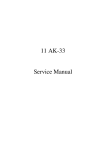
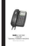
McMurdo F1 DSC Marine VHF Radio with DSC Installation Manual Introduction McMurdo McMurdo has supplied the maritime market for many years with communication products of high quality and excellent design, and considers it of utmost importance that all products are safe and easy to operate. The product The McMurdo F1 DSC VHF Radiotelephone (radio transceiver) is designed to meet the high quality standard required for a product that plays an important role in the safety of the ship and its crew. The F1 DSC Radiotelephone is easy to operate and gives the user high quality effective radio communication to other ships as well as to shore based stations. Installation and maintenance is made very simple and can be carried out by untrained personnel. Training certificate The F1 DSC Radiotelephone is very simple to use; the menu-structured operation is user-friendly, self-explanatory and simple to navigate. However the use of VHF marine radios including DSC is legislated; it is therefore necessary for the user to have a certificate from the legislating authority in the country where the radio is to be used. When the radio is registered the legislating authority will issue the MMSI number necessary for the operation of the DSC function. A CD-ROM simulating the operation of the F1 DSC Radiotelephone can be obtained from McMurdo on application. This, when installed on a PC-compatible computer, simulates the operation of the F1 DSC Radiotelephone together with a simulation of a second station for exchange of DSC messages. Service McMurdo has established a worldwide service network ready to support any requirement concerning the F1 DSC Radiotelephone. The service network ensures that spare parts and installation advice can be obtained in all major ports of the world. The Certified Services Centre concept ensures that the performance of the Service Centres is constantly monitored and that the skills of the personnel are up to date. Details of the McMurdo worldwide service network can be found on the website: www.mcmurdo.co.uk ii Maintenance The F1 DSC Radiotelephone is an essential part of the ship’s emergency system. As the radio is a vital component for the safety of the ship and its crew it is very important to maintain the radio and its installation to a very high standard. The design of the radio ensures that maintenance can be kept to a minimum, however it is good practice to perform a functional check at least once every month. This functional check is described in this manual and takes only a few minutes to carry out. It is essential to perform a functional check following installation. It is also important to inspect all cables and connections at regular intervals, such as twice yearly. Disclaimer Information contained in this manual is supplied in good faith, but is liable to change without notice. McMurdo Limited disclaims any liability for consequences arising from omissions or inaccuracies in the manuals and documentation provided with this product. IMPORTANT: Please take time to read this manual carefully and to understand its contents fully, so that you can install your F1 DSC Radiotelephone correctly. If in any doubt seek expert advice or have a skilled person install it for you. Once installed please read the Operation Manual fully to make sure you understand how to use your new radio. 2002 McMurdo Ltd. iii Installing and Using the Transceiver Safely Installation WARNING: Do not connect the transceiver to a mains (line) AC electrical supply, as an electric shock or fire hazard could result. CAUTION: Do not connect the transceiver to a DC supply exceeding 16V or reverse the supply polarity. Damage to the transceiver can result. CAUTION: Do not bypass the power cable inline fuse (such as cutting the cable shorter). CAUTION: The transceiver is designed for operation in the temperature range –15°C to +55°C. Do not install (or use) the transceiver in areas which exceed this range. CAUTION: The F1 DSC radio is water resistant to international standards. However, if either the transceiver or microphone casing is damaged (e.g. due to heavy impact) then the sealing cannot be guaranteed. WARNING: Do not install the receiver in a position where; a) the controls of your vessel may be obstructed. b) it may obstruct your normal movement around your vessel. c) it may cause bodily injury. d) it cannot be easily accessed in an emergency. Use WARNING: Certain parts of the chassis can become hot during extended periods of operation, notably the rear panel (connectors and radiator fins). Avoid touching these areas when the radio is operating. WARNING: Do not touch the rear connections, notably the antenna connector, when the transceiver is operating and do not touch the antenna whip (mast) or connecting cable when operating the transceiver, for RF exposure and electrical safety reasons. Refer to Radio Frequency Exposure Warning. WARNING: Opening the transceiver cover will invalidate the warranty. Do not open the cover when the transceiver is operating, or connected to a power supply. Maintenance CAUTION: Avoid using chemical solvents to clean the transceiver as some solvents can damage the case material. NOTE: The transceiver contains no user serviceable parts. Return to your Service Agent for repair. iv Radio Frequency Exposure Warning To meet the current requirements for Radio Frequency Exposure it is necessary to install the antenna mast correctly and operate the equipment according to the instructions. WARNING: The antenna mast must be mounted at a minimum distance (vertical separation) of 3 metres from the head of any person standing on deck to meet international safety directives on Maximum Permissible Exposure (MPE) / Specific Absorption Rate (SAR). The assumptions used in this assessment are: full transmit power is used, a good antenna is used (assumed to be a 9dBi gain omnidirectional type). Where no suitable structure exists to achieve a 3 metre vertical separation then the antenna base must be mounted at least 1 metre above the head of any person within range and all persons must stay outside the 3 metre safety radius. WARNING: Do not transmit when persons are closer than 3 metres to the antenna. If any person (e.g. the operator) must be closer, then a grounded RF shield should be interposed between that person and the antenna. Failure to adhere to these limits could expose persons within the 3 metre radius to RF radiation in excess of the MPE / SAR limits. Rules of Operation Licensing IMPORTANT: In most countries the operator of the transceiver must possess a current radio telephone licence, and the equipment must be registered (Call Sign and MMSI number). Please contact the relevant authority in your country for more information. IMPORTANT: Normal users of the transceiver should be trained, licensed operators, but this rule is waived in an emergency and any person can transmit a Distress Call. Please refer to the F1 DSC Radiotelephone Operation Manual for full radio operating procedures. v Contents Installing the MMSI number................................................................1 Applying for a MMSI number ................................................................................ 1 How to install the MMSI number ........................................................................... 1 Mounting options ................................................................................3 Introduction ........................................................................................................... 3 Tabletop or ceiling installation............................................................................... 4 Bulkhead or panel mounting ................................................................................. 6 Flush mount kit (kit number 84-412) ..................................................................... 6 Bulkhead and instrument panel mounting kit (kit number 84-413) ........................ 8 Drilling guides.....................................................................................9 Electrical connections.......................................................................11 Connection of power supply................................................................................ 11 Connection of external loudspeaker.................................................................... 13 Connection of GPS for position information ........................................................ 14 Connection of fist mike to the rear D-sub connector (socket) ............................. 15 Connection of fist mike to the D-sub plug ........................................................... 16 Connection of antenna........................................................................................ 17 Performance check ..........................................................................19 Technical Specifications...................................................................20 McMurdo Limited Product Warranty.................................................22 vi Installing the MMSI number To ensure full performance of the F1 DSC Radiotelephone it is essential that the MMSI number is installed in the radio. WARNING: If no MMSI number is installed the radio will be unable to transmit a DSC call including the transmission of a DSC distress alert. Applying for a MMSI number It is necessary to apply for a radio licence and a MMSI number to the national authority, which in most cases has a standard form to be completed. In Britain the national authority is the Radiocommunication Agency (RA); the standard form can be found on the webpage www.radio.gov.uk, then follow the menu items: M – Maritime radio – Application forms – RA145. The supplier of the radio will be able to advise concerning the procedure and form used to apply for a radio licence including the MMSI number. How to install the MMSI number The MMSI number is a 9-digit number which is programmed into the radio. When programmed once it is not possible for the operator to alter the number without returning the radio to the supplier or to McMurdo Ltd. To program the MMSI follow these illustrations: 1. Turn on the Radio 2. When the radio shows the standby display Press the Menu action key 3. Use the scroll key to display the menu “Profiles” and press the Select action key 49° 45` W at: 11:23 123°32` E UTC 16 Menu Pos Profiles Select Exit Profiles MMSI number 4. Use the scroll key to display the menu “MMSI number” and press Select action key Select MMSI number Ship MMSI 5. The first option displayed is “Ship MMSI”. Press the Select action key Select 6. The cursor will be placed behind the last 0 Use the Clear action key to delete all 0’s then key in the MMSI number Back Back Ship MMSI number MMSI:000000000 Save Clear 7. The MMSI number is saved by pressing the Save action key Page 1 IMPORTANT: If the wrong MMSI number has been entered, it is possible to re-enter (correct) the MMSI number once more only. However, after one hour from the time of entering the first MMSI number the radio will inhibit changing the MMSI number. If this happens, the radio must be returned to McMurdo (via the supplier) for reprogramming to allow entering another MMSI number. Page 2 Mounting options Introduction To ensure high performance of the F1 DSC Radiotelephone it is very important that the installation guidelines described in this book are followed. When installed make sure the radio is fixed to a solid surface. The mounting surface to which the radio is fixed must be as solid and as free of vibrations from the ship's engine or other vibration generating sources as possible. Extensive vibrations can damage the communication quality and in the worst case make communication impossible. Cables specified in this installation manual are recommendations only, but to achieve the full performance of your radio it is advisable to follow these recommendations. The cables specified are not shielded, but it is recommended to use shielded cables when other electronic instruments are mounted close to the radio. Special attention has to be paid to cables from another instrument running parallel to the cables for the F1 DSC Radiotelephone and to cables carrying high alternating current. Such cables can cause radio interference, which can disturb communication on one or more of the VHF channels. The F1 DSC Radiotelephone uses components containing magnets. To ensure correct operation of your compass, it is necessary to mount the radio transceiver no closer than 0.5 metres to any compass installed in the vessel. The VHF communication range is limited to line of sight. It is therefore very important that the antenna is installed as high and as free of obstacles as possible. It is also important to ensure that the connection from the antenna to the radio uses a 50Ω low loss cable, and that the connectors used are of the recommended type and fit the cable used. The recommended coax cables RG58 and RG214 or equivalent must be installed with caution; it is a good principle not to bend the cables to a smaller radius than 10 times the cable diameter. In sailboats the antenna is often installed at the top of the mast, requiring a long cable between the radio and the antenna. To obtain the maximum performance of your radio it is recommended to use a low loss coax cable; the RG214 is a low loss cable. WARNING: Observe the Radio Frequency Exposure Warning in the front section of this manual regarding installation of the antenna. The F1 DSC Radiotelephone is watertight; if installed following the instructions in this manual, the complete installation will be watertight also. When installing in a bulkhead it is recommended to use the McMurdo bulkhead installation kit, which is available in two versions: a bulkhead mounting kit and a flush mounting kit. Both kits will when installed with care create a watertight seal. Page 3 Tabletop or ceiling installation The F1 DSC Radiotelephone can be mounted on top of a table or on the ceiling. The supplied bracket is used to mount the radio in these positions. The mounting bracket is supplied with 6 installation screws; it is recommended to use all 6 screws. (See ‘Drilling guides; on page 9.) Before the bracket is fixed to the table or the ceiling make sure that there will be enough room for the radio and the cables. The main dimensions are shown in the figures below. When the tabletop bracket is mounted, install the radio and find the angle that will be most suitable for operating the radio, then tighten the lock knob. When the radio is in position in the bracket connect the necessary cables, but make sure that enough cable length is available for future readjustment of the radio. Page 4 Page 5 Bulkhead or panel mounting For bulkhead or panel mounting of the F1 DSC Radiotelephone two mounting kits are available: a flush mounting kit and a simple bulkhead/panel mounting kit. Flush mount kit (kit number 84-412) The flush mounting kit when installed properly provides a watertight installation of the radio in a bulkhead or instrument panel. Before the hole is cut in the bulkhead or the instrument panel, make sure that the space behind the bulkhead or instrument panel is sufficient to accommodate the radio and connecting cables. In the illustration the dimensions of the required space are shown. The illustration also shows an exploded view of the assembly process. A cutout template is provided in the flush mounting kit; take particular care to be accurate when cutting the hole. If the hole is too large the installation may not be watertight or the installation may appear untidy. When using the flush mount kit the connection point for the fist mike must be changed because the flush mount covers the usual connection of the fist mike at the bottom of the fascia. As shown below the fist mike connection becomes part of the flush mount kit. A wire loom is provided to connect the fist mike to the rear of the radio. Page 6 Page 7 Bulkhead and instrument panel mounting kit (kit number 84-413) Use of the bulkhead and instrument panel mounting kit is a simple way to build in the F1 DSC Radiotelephone. Screws are provided with this mounting kit. Before the hole is cut in the bulkhead or the instrument panel, make sure that the space behind the bulkhead or instrument panel is sufficient to accommodate the radio and connecting cables. The dimensions of the required space are shown in the illustrations below. Note that unlike the Flush Mount Kit (see page 6) the panel thickness is limited to 12mm due to the slightly different construction of the Simple Bulkhead/Panel Kit. A cutout template is provided in the mounting kit; take particular care to be accurate when cutting the hole. If the hole is too large the installation may not be watertight or the installation may appear untidy. Page 8 Drilling guides Table top bracket drilling guide Page 9 Flush mount kit cutting guide Bulkhead and instrument panel mount kit cutting guide A full size template is provided with each mount kit. Page 10 Electrical connections It is recommended that this guideline for electrical connection of the F1 DSC Radiotelephone is followed as carefully as possible. A careless installation is likely to degrade performance of the radio and cause difficulties for the operator. Most radio installations will be undisturbed for many years so it is therefore important that the materials chosen are suitable for use onboard ship where they will be in contact with the harsh environment onboard. WARNING: The F1 DSC Radiotelephone will in most cases be connected to the ship's battery. During installation special care must be taken not to short the battery terminals as this can cause severe burns, or in the worst case can cause a fire. The radio will operate when it is connected to the power supply and to the antenna. These are the only two connections which are necessary for full functionality of the radio. However, if the radio is connected to a GPS source, position information stored in the radio will be automatically updated at regular intervals and it will not be necessary to update this position manually. Connection to a GPS will ensure that the position transmitted in a DSC distress call is as accurate as possible. In an environment with considerable electrical noise the earth screw at the rear of the radio should be connected to a common earth point. This is particularly important when the radio is installed together with MF/HF radios. It is also advisable to route power, data and antenna cables away from sources of electrical noise such as an engine. CAUTION: The battery negative or positive terminal must not be connected to the earth screw under any circumstances, as this may cause electrolytic corrosion. An external loudspeaker can be connected to the two central pins in the power plug (see page 13). The external loudspeaker can be switched on/off via the Speaker Settings (in Profiles). An additional fist mike can be connected via the 15 pole D-sub connector at the rear of the radio. This additional connection is in parallel with the fist mike attached to the front. Connection of power supply The power supply is connected as shown. If it is necessary to extend the wires from the connector, the wire dimensions should be as specified. WARNING: You must fit an external inline fuse with a 10A fast blow rating in the positive (plus) supply cable (see page 12). The nominal power supply voltage is 12V. The radio will operate over the supply range of 10.8 VDC to 15.6 VDC. If it is necessary to connect the radio to a 24V battery, a 24V to 12V voltage converter must be used. The F1 DSC Radiotelephone is protected against reverse voltage polarity by an internal diode and fuse. If reverse polarity is applied to the radio the internal fuse will open (fail) and must then be replaced by a service agent. Page 11 Table 1 Supply 12 VDC 12 VDC Page 12 Recommended wire size for connection of power supply From Battery Battery To F1 DSC F1 DSC Wire mm2 2.5 5.0 Maximum length 1.5m 3.0m Connection of external loudspeaker An external loudspeaker may be connected to the F1 DSC Radiotelephone. The external speaker is connected to the two wires in the power plug intended for this use. If it is necessary to extend the wires to the external loudspeaker, wire dimensions as specified should be used. Table 2 Speaker 4 ohm 4 ohm Recommended wire size for connection of external speaker From F1 DSC F1 DSC To Speaker Speaker Wire mm2 0.75 1.5 Maximum length 3.0m 6.0m Page 13 Connection of GPS for position information The position information used in the DSC distress message can be entered manually from the keyboard, but to ensure that the position information is valid at all times a GPS can be connected to the radio. The information transmitted from a GPS uses a standard interface, designated NMEA 0183. The F1 DSC Radiotelephone can be connected to this GPS interface directly via the two wires to the 15 pin D-sub connector. The NMEA protocol transmits the position information via named sentences. The named sentences that can be used are: GGA, GLL, GNS, RMC and ZDA. Table 3 Recommended wire size for connection of GPS If it is necessary to use longer wires than those provided with the radio, wire dimensions as specified should be used. As the GPS connection is sensitive to electrical noise use of shielded twisted cable is recommended. GPS NMEA 0183c NMEA 0183c Page 14 From F1 DSC F1 DSC To GPS GPS Wire mm2 0.25 0.50 Maximum length 5.0m 10.0m Connection of fist mike to the rear D-sub connector (socket) When the flush mounting kit is used for bulkhead or instrument panel installation of the F1 DSC Radiotelephone it is necessary to connect the fist mike to the D-sub connector at the rear of the radio. A wire loom is provided to connect the fist mike to the rear of the radio. The illustration below shows how this loom is connected. Page 15 Connection of fist mike to the D-sub plug If for a particular installation the attachment of the fist mike to the front of the radio is inconvenient, the mike can be connected to the D-sub connector at the rear of the radio, as shown. Table 6 Connection of fist mike to D-sub connector FISTMIC REAR CONN. PIN White 8 Grey 9 Black 15 Page 16 SIGNAL PTT2 Mic2+ -POWER FUNCTION Press To Talk line for rear socket Positive connection for microphone Ground Connection of antenna The antenna and the antenna cable are a very important part of the radio installation and it is therefore very important to use good quality materials. The antenna must be marked as a VHF antenna covering at least the frequency band from 153MHz to 163MHz. VHF antennas for use on leisure ships typically have 0dB or 3dB gain (although specialised antennas may have gains as high as 9dB). Depending on the environment, the 3 dB gain antennas can give better coverage and together with a low loss antenna cable will ensure greater radiated signal power and better receiver sensitivity. When securing the antenna plug to the coax cable make sure that the cable is prepared to the dimensions shown in the illustration below. A frequent cause of poor communication is that the antenna connection is faulty, therefore make sure that this connection is properly made and that it is inspected at regular intervals. Page 17 Table 4 Coax cable signal losses Typical cable losses for two common types of coaxial cable. Cable type RG 58 RG 214 Cable loss per meter for VHF channels 2.0 dB/10 meter cable 0.8 dB/10 meter cable Line of sight As a general rule the VHF communication range is the same as the line of sight distance, which means that the receiver antenna must be able to see the transmitter antenna. Line of sight depends on eye height above water level of the transmitter and of the receiver. As the “eye” of the radio is the antenna, the communication range depends on the height above water level of the antennas. The illustration shows the line of sight (the curvature of the Earth is exaggerated for clarity). Table 5 Line of sight distances h2 (m) h1 (m) 0.5 1 3 5 10 30 0.5 3.1 3.8 5.4 6.6 8.6 13.8 1 3.8 4.5 6.1 7.2 9.2 14.4 3 5.4 6.1 7.7 8.8 10.9 16.1 5 6.6 7.2 8.8 10.0 12.0 17.2 10 8.6 9.3 10.9 12.0 14.1 19.3 30 13.8 14.4 16.1 17.2 19.3 24.4 h1 and h2 are the heights above sea level of the transmit and receive antennas. Distances are in nautical miles. Page 18 Performance check To make sure that the radio performance is satisfactory, it is advisable to carry out a performance check of the radio installation at regular intervals. • Installation, cables, connectors and antenna should be visually inspected at least once a year. • A performance check as detailed below should be carried out at least every month. • A performance check as given below should be carried out after installation or repair. Performance check 1. Turn the radio on. 2. If a GPS is connected to the radio wait until position update is found. 3. If no GPS is connected to the radio, key in a valid position and time. 4. Adjust the squelch and make sure that the squelch can silence the radio. 5. Make a telephony call to a coast station: • Ask for radio check 6. Make sure that the coast station operator can read you clearly and that you can read the coast station clearly. 7. If the called coast station is capable of receiving DSC messages, ask for a DSC test call to be made; make sure that the coast station MMSI is at hand. 8. Make an individual DSC call to the coast station. 9. Wait for acknowledgement. 10. When acknowledgement is received, call the coast station on the suggested working channel to confirm that the test has been carried out successfully. For instructions on how to use the F1 DSC Radiotelephone and set up a DSC call see the Operation Manual. Page 19 Technical Specifications The McMurdo F1 DSC Radiotelephone conforms to all relevant international requirements agreed for a VHF DSC class D radiotelephone by ETSI, IEC, ITU and IMO. These specifications include ETSI 301 025, IEC 62238, IEC 60945, ITU-R M.493-10 and ITU-R M.541-8 General Information International channels US channels Transceiver dimensions Transceiver weight All channels for international 25kHz operation All channels for US waters with 25 kHz spacing All US weather channels 30 programmable channels for 25kHz operation 25kHz Simplex/semi-duplex G3EJN for telephony operation G2B for DSC operation 10ppm SO239 50 ohm female -15°C to +55°C 12 V DC nominal, range 10.8 to 15.6V DC 0.23A standby 1.6A transmit low power 5.0A transmit high power 85mm h x 195mm w x 180mm d 2.1kg Receiver Sensitivity AF internal speaker AF external speaker Distortion THD Signal/noise ratio AF response Spurious emission Spurious response Intermodulation attn. Blocking better than Co-channel rejection Adjacent ch. selec. -119dBm for 12dB SINAD 4W/4 ohms 4W/4 ohms < 5% > 40dB 6dB/octave < 2nW < 70dB > 68dB > 90dBmV > 10dB > 70dB Private channels Channel spacing Operation modes Modulation Frequency stability Aerial connector Temperature range Supply voltages Supply current Page 20 Transmitter RF output power Adjacent ch. power Spurious radiation Cabinet radiation AF response Signal/noise ratio DSC Facilities DSC operation DSC protocol Navigator interface Symbol error rate Modulation Frequency error Residual DSC-mod. High 25W +0dB, –2dB Low 1W +0dB, –3dB < 70dBc < 0.25mW < 0.25mW +6dB/octave > 40dB According to Rec. ITU-R M.541-8 According to Rec. ITU-R M.493-10 class D NMEA 0183, GGA, GLL, GNS, RMC and ZDA < 1x10 -2 for –119dBm 1700 Hz +400 Hz 1200 baud +30 ppm < +1 Hz < 26 dB Page 21 McMurdo Limited Product Warranty Subject to the provisions set out below McMurdo Limited warrants that this product will be free of defects in materials and workmanship for a period of 24 months from the date of purchase. McMurdo Limited will not be liable to the buyer under the above warranty:• for any defect arising from fair wear and tear, wilful damage, negligence, abnormal working conditions, failure to follow McMurdo Limited's instructions (whether oral or in writing) including a failure to install properly and/or to use the recommended DC supply, misuse or alterations or repair of the product by persons other than McMurdo Limited or an Approved Service Agent; • for parts, materials or equipment not manufactured by McMurdo Limited in respect of which the buyer shall only be entitled to the benefit of any warranty or guarantee given by the manufacturer to McMurdo Limited; • if the total price for the product has not been paid. McMurdo Limited does not make any other promises or warranties (express, implied or statutory) about the product except where the product is sold to a consumer in which case the statutory rights of a consumer are not to be affected. In order to be valid, claims must be made under the above warranty in writing as soon as practicable after discovery of the defect or failure and within the warranty period referred to above. Proof of purchase will be required. The claim should be sent together with the product in question to the address set out below or to an Approved Service Agent. Following a valid warranty claim McMurdo Limited shall be entitled to repair or replace the product (or part) in question free of charge, or at McMurdo Limited's sole discretion to refund to the buyer the price of the product (or a proportional part of the price). McMurdo Limited shall not be liable to a buyer who is not a consumer for any other loss or damage (whether indirect, special or consequential loss of profit or otherwise) costs, expenses or other claims for compensation which arise out of or in connection with this product. In the case of a consumer McMurdo Limited shall only be liable where other loss or damage is foreseeable. Nothing shall limit McMurdo Limited's liability for death or personal injury caused by its negligence. This warranty is to be interpreted under English law. All enquiries relating to this warranty or Approved Service Agents should be sent to: McMurdo Limited Silver Point, Airport Service Road, Hampshire, PO3 5PB, United Kingdom Telephone: Int + 44 (0) 23 9262 3900 Fax: Int + 44 (0) 23 9262 3999 Web: www.mcmurdo.co.uk Email:[email protected] Page 22 Declaration of Conformity The Declaration of Conformity is provided as a separate document. Page 23 Notes Page 24 Page 25 Record Serial No.: MMSI: Date of Purchase: Dealer Stamp McMurdo Ltd Silver Point Airport Service Road Portsmouth Hampshire United Kingdom PO3 5PB A member of Chemring Group PLC www.mcmurdo.co.uk 84-783 Issue 1 Page 26