1
1997
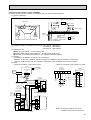
SPLIT-TYPE,HEAT PUMP AIR CONDITIONERS
No. OC148
TECHNICAL & SERVICE MANUAL
Series PLH Ceiling Cassettes
[Model names]
PLH-3GK(H)B
PLH-4GK(H)SB
PLH-5GK(H)SB
PLH-6GK(H)SB
This manual does not cover the following
outdoor units.
When servicing them,
please refer to the service manual
No.OC150 and this manual in a set.
[Service Ref.]
PUH-3YKA2.UK
PUH-3VKA2.UK
PUH-4YKSA2.UK
PUH-5YKSA2.UK
PUH-6YKSA2.UK
[Service Ref.]
PLH-3GK(H)B1.UK
PLH-4GK(H)SB1.UK
PLH-5GK(H)SB1.UK
PLH-6GK(H)SB1.UK
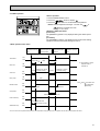
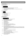
CONTENTS
INDOOR UNIT
FILTER
CHECK MODE
TEST RUN
REMOTE CONTROLLER
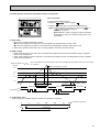
1. FEATURES ···········································3
2. PART NAMES AND FUNCTIONS ········5
3. SPECIFICATIONS·································7
4. DATA ···················································11
5. OUTLINES AND DIMENSIONS··········15
6. WIRING DIAGRAM·····························18
7. REFRIGERANT SYSTEM DIAGRAM ······19
8. OPERATION FLOW-CHART ··············20
9. MICROPROCESSOR CONTROL·······24
10. TROUBLESHOOTING ························47
11. 4-WAY AIR FLOW SYSTEM ···············55
12. SYSTEM CONTROL ···························60
13. DISASSEMBLY PROCEDURE ···········65
14. PARTS LIST········································68
15. OPTIONAL PARTS ·····························78
The Slim Line.
From Mitsubishi Electric.
1
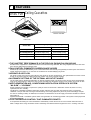
FEATURES
Series PLH Ceiling Cassettes
FILTER
CHECK MODE
TEST RUN
Remote controller
Indoor unit
Cooling capacity/Heating capacity
Service Ref.
W
Btu/h
PLH-3GK(H)B1.UK
26,300/28,700[35,800]
7,700/ 8,400[10,500]
PLH-4GK(H)SB1.UK
33,100/35,500[44,400]
9,700/10,400[13,000]
PLH-5GK(H)SB1.UK
42,300/45,700[56,000]
12,400/13,400[16,400]
PLH-6GK(H)SB1.UK
46,100/54,300[64,500]
13,500/15,900[18,900]
1.THE QUIETEST PERFORMANCE IN THE FIELD-39 PHONS(PLH-3GK(H)B.UK)
Excellent noise suppression is achieved because of the turbofan’s large diameter. Also wing-shaped vanes and a low-resistance air flow desigh help to suppress noise.
2.FAN CONTROL ELIMINATES SUDDEN,SHARP NOISES
Sudden,sharp noises are eliminated by a fan control mechanism that smoothly and gradually increases rpms when the thermostat switches the heater on or when the air conditioners in the dehumidifying“dry”mode.
3.VERSATILE AIR FLOW
Fan phase control and computer control allow a wide variety of air flow configurations. The optimal blown-air volume can be
chosen in accordance with the ceilling height and number of air vents at specific settings.
4.AUTOMATIC SETTING OF THE OPTIMAL AIR OUTLET ANGLE
The air outlet angle is altered automatically,to an almost horizontal angle of 20˚during cooling and an almost perpendicular
angle of 65˚during heating,to deliver the most comfort possible.This mechanism gives an even greater control over air flow.
5.NEXT-GENERATION AIR -CONDITIONING VENTILATION INTERLOCK SYSTEM
“Mr.SLIM” + “LOSSNAY”
Proper ventilation is important to improve the quality of indoor environments. lt eliminates unclean air,which is not only
unpleasant,but also unhealthy.
The“Mr.SLM”+“LOSSNAY”ventilation interlocking system achieves high air quality with minimum energy consumption.
LOSSNAY´s unique total heat exchanger reduces heating and cooling expenses by about 25 percent annually(in comparison with our exisiting models). ln addition,its mechanism of simultaneous forced air supply and exhaust enables it to deliver
high quality air.
Together the“Mr.SLIM”+“LOSSNAY”system makes next-generation air conditioning possible. This system is both people-and
environmental-friendly.
6.FLUCTUATING AIR CONTROL THAT ELIMINATES DRAFTS
A computerized fluctuating air control mechanism automatically controls the flow of air so that it feels natural and free of
drafts. Linkage with a swing mechanism sends a refreshing and natural breeze throughout the room. <Cooling><Air flow>
3
7.INCREASED DEHUMIDIFICATION WITH FAN PHASE CONTROL NEW ELECTRONIC
DEHUMIDI-FIER OPERATION
A new electronic dehumidifier mode,where fan speed is controlled precisely by fan phase control,increases dehumidification
volume and raises dehumidifying effectiveness.This results in a pleasant environment all-year around,even during extended
rainy seasons.
8. A90˚GRILL SWITCHING MECHANISM MAKES INSTALLATION CONSIDERABLY EASIER (3HP)
The direction of the panel designs can be adjusted to match the interior desigh of the space in which tyey are being used.
This allows for greater flexibillty in air conditioning space and plumbing work.
9.HIGH-PERFORMANCE FILTER(colorimetric method:65%)OPTION
A high-performance filter can be installed(colorimetric method:65%)by setting the blown-air volume switch SWC.
10.OUTSIDE AIR INCORPORATION
lnstallation of an outside air intake casement(option)allows fresh air
from outside to be incorporated with limited pressure loss.
11.ADVANCED MICROPROCESSOR
(1)Easy to use microprocessor
1)Ultra-thin remote controller
The streamlinde,square controller is designed to blend well with
any interior.Also,the sophisticated microproceeor allows you to
easily carry out a wide range of operations.
2)Attractive liquid crystal display(LCD)
The unit´s operation mode,set temperature,room
temperature,timer setting,fan speed,louver oper-ation,and air flow
direction are displayed on the remote controller´s easy-to-read
Liquid Crystal Dis-play(LCD).
3)Convenient 24-hour ON-OFF timer
The timer switches Mr.SLIM on and off automati-cally at the time
you set. Once the timer is set,the remaining time is shown on the
LCD.
FILTER
CHECK MODE
TEST RUN
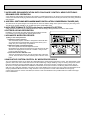
12.INNOVATIVE SYSTEM CONTROL BY MICROPROCESSORS
The most significant feature of the series PLH-GK(H)(S)B is the advanced microprocessor control. The development of this
system is due to the recent world-wide trend in the air conditioning of larger buildings. They are moving away from centralized duct systems and using individual split type units instead. There are a number of reasons for this change. First of
all,the duct´s costly,and troublesome installation is eliminated. Second,the overall air conditioning balance is excellent in
split type units. Lastly,the operation costs are low due to the flexible control of each unit. This system was developed exclusively by Mitsubishi Electric because of high demand. The microprocessor control makes individual control,group
control,control using two remote controllers,and remote on/off and individual control possible without trouble-some equipment modifications.
4
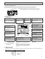
2
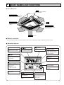
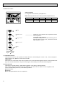
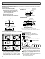
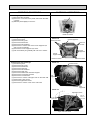
PART NAMES AND FUNCTIONS
● Indoor (Main) Unit
Filters
Remove dust and pollutants
from inihaled air
Horizontal Air Outlet
Sets airflow horizontal automatically
during cooling or dehumidifying.
Downward Air Outlet
Sets airflow downward
automatically during
heating.
Grill
Auto Air Swing Vane
Disperses airflow up and
down and adjusts the angle
of airflow direction.
Air Intake
Inhales air from room.
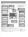
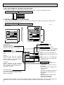
● Remote controller
On the controls are set, the same operation mode can be repeated by simply pressing the ON/OFF button.
● Operation buttons
button
button
button
This switches between continuous
operation and the timer operation.
This sets of switches the current
time. start time and stop time.
This sets the ventilation fan
speed.
ON/OFF button
This switches between the operation
and stop modes each time it is
pressed. The lamp on this butoon
lights during operation.
button
Press this button to switch the cooler
electronic dry (dehumidify) automatic
and heater modes.
button
FILTER
This adjusts the vertical angle of the
ventilation.
CHECK MODE
TEST RUN
TEMP button
This sets the room temparature The
temparature setting can be performed in 1°C units
Setting range
Cooler 19°C to 30°C
Heater 17°C to 28°C
This model name of the remote controller is indicated.
FILTER button
This resets the filter service indication display.
button
CHECK-TEST RUN button
This switches the horizontal fan
motion ON and OFF.
Only press this button to perform an inspection check or test
operation Do not use it for
nomal operation.
(This button does not operate in this
model)
5
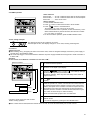
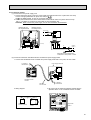
● Display
CENTRALLY
CONTROLLED display
This indicates when the unit is controlled by optional features such as
central control type remote controller.
In this display example on the bottom left, a condition where all display lamps light is shown for explanation purposes although this differs
from actual operation.
display
The current time , start time and stop
time can be displayed in tensecond
intervals by pressing the time switch
button. The start time or stop time is
always displayed during the timer
operation.
display
display
display
The selected fan speed is displayed.
This displays the air
direction.
This indicates when the continous
operation and time operation modes
are set.
It also display the time for the timer
operation at the same time as when
it is set.
display
FILTER
OPERATION MODE display
The temperature of the suction air is
displayed during operation. The display range is 8° to 39°C. The display
flashes 8°C when the actual temperature is less than 8° and flashes
39°C when the actual temperature is
greater than 39°C.
CHECK MODE
TEST RUN
This indicates the operation mode.
Operation lamp
This lamp lights during operation,
goes off when the unit stops and
flashes when amalfunction occurs.
STANDBY display
This indicates when the standby
mode is set from the time the sleep
operation starts until the heating air
is discharged.
CHECK MODE
FILTER
DEFROST display
This indicates when the defrost operation is performed.
This lamp lights when the filter need
to be cleaned.
CHECK display
display
This indicates when a malfunction
has occurred in the unit which should
be checked.
display
This displays the selected setting
temperature.
TEST RUN
display
This display lights in the check mode
or when a test operation is performed.
display
This lamp lights when electricity is
supplied to the unit.
Caution
● Only the
display lights when the unit is stopped and power supplied to the unit.
● When power is turned ON for the first time the (CENTRAL CTRL) display appears to go off momentarily but this is not a
malfunction.
● When the central control remote control unit, which is sold separately, is used the ON-OFF button,
button and
TEMP button do not operate.
● “NOT AVAILABLE” is displayed when the
button are pressed.This indicates that this room unit is not equipped with
the fan direction adjustment function and the louver function.
6
3
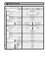
SPECIFICATIONS
Service Ref.
Item
Function
Btu/h
W
kW
Capacity
Total input
Service Ref.
Power supply(phase, cycle,voltage)
Input
Running current
Starting current
External finish
Heat exchanger
Fan(drive) x No.
Fan motor output
Airflow(Low-High)
External static pressure
Booster heater
Operation control & Thermostat
Noise level(Low-High)
Cond. drain conn. O.D.
kW
A
A
REFRIGERANT
PIPING
kW
K/ min (CFM)
Pa(mmAq)
kW
W
D
H
Weight
Service Ref.
Power supply (phase, cycle, voltage)
Input
Running current
Starting current
External finish
Refrigerant control
Compressor
Model
Motor output
Starter type
Protection devices
Heat exchanger
Fan(drive) x No.
Fan motor output
Airflow
Defrost method
Noise level
Dimensions
Weight
Refrigerant
Charge
Cooling
26,300
7,700
3.31
Heating
28,700[35,800]
8,400[10,500]
3.10[5.20]
PLH-3GK(H)B1.UK
Single, 50Hz, 220-240V
INDOOR UNIT
OUTDOOR UNIT
Dimensions
PLH-3GK(H)B.UK
dB(A)
mm,(in)
mm,(in)
mm,(in)
mm,(in)
kg,(lbs)
kW
A
A
kW
kW
K/ min (CFM)
W
D
H
dB(A)
mm,(in)
mm,(in)
mm,(in)
kg,(lbs)
kg,(lbs)
mm,(in)
Liquid
Pipe size O.D.
mm,(in)
Gas
Indoor side
Connection method
Outdoor side
Height difference
Between the indoor & outdoor units
Piping length
0.16
0.16[2.26]
0.72
0.72[9.5]
1.00
1.00[9.8]
Galvanized sheets with gray heat insulation
Plate fin coil
Turbo fan (direct) x 1
0.050
14-18(495-640)
0(direct blow)
[2.1]
Remote controller & built-in
32-39
30(1-1/4)
UNIT : 820(32-1/4)
PANEL : 950(37-3/8)
UNIT : 820(32-1/4)
PANEL : 950(37-3/8)
UNIT : 258(10-1/8)
PANEL : 65(2-9/16)
UNIT : 29(64)
PANEL : 7(16)
PUH-3VKA2.UK/PUH-3YKA2.UK
Single, 50Hz, 220-240V/3, 50Hz, 380-415V(4wires)
3.15
2.94
13.82/5.16
12.89/4.81
58/37
58/37
Munsell 5Y 7/1
Capillary tube
Hermetic
NH52VND/NH52YDA
2.2/2.4
Line start
w1
Plate fin coil
Propeller (direct) x1
0.085
50(1764)
Reverse cycle
52
870(34-1/4)
295+24 (11-5/8 add 1)
850(33-1/4)
75(165)
R-22
3.2(7.1)
9.52 (3/8)
15.88(5/8)
Flared
Flared
Max. 50m
Max. 50m
w V …Internal Thermostat, HP switch
Y …Anti-phase protector, thermal relay, thermal switch, HP switch
7
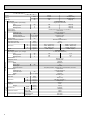
Service Ref.
Item
Function
Btu/h
W
kW
Capacity
Total input
Service Ref.
Power supply(phase, cycle,voltage)
Input
Running current
Starting current
External finish
Heat exchanger
Fan(drive) x No.
Fan motor output
Airflow(Low-High)
External static pressure
Booster heater
Operation control & Thermostat
Noise level(Low-High)
Cond. drain conn. O.D.
kW
A
A
REFRIGERANT
PIPING
8
kW
K/ min (CFM)
Pa(mmAq)
kW
W
D
H
Weight
Service Ref.
Power supply (phase, cycle, voltage)
Input
Running current
Starting current
External finish
Refrigerant control
Compressor
Model
Motor output
Starter type
Protection devices
Heat exchanger
Fan(drive) x No.
Fan motor output
Airflow
Defrost method
Noise level
Dimensions
Weight
Refrigerant
Charge
Cooling
33,100
9,700
3.46
Heating
35,500[44,400]
10,400[13,000]
3.45[6.05]
PLH-4GK(H)SB1.UK
Single, 50Hz, 220-240V
INDOOR UNIT
OUTDOOR UNIT
Dimensions
PLH-4GK(H)SB1.UK
dB(A)
mm,(in)
mm,(in)
mm,(in)
mm,(in)
kg,(lbs)
kW
A
A
kW
kW
K/ min (CFM)
W
D
H
dB(A)
mm,(in)
mm,(in)
mm,(in)
kg,(lbs)
kg,(lbs)
mm,(in)
Liquid
Pipe size O.D.
mm,(in)
Gas
Indoor side
Connection method
Outdoor side
Height difference
Between the indoor & outdoor units
Piping length
0.26
0.26[2.86]
1.18
1.18[12.0]
1.50
1.50[12.3]
Galvanized sheets with gray heat insulation
Plate fin coil
Turbo fan (direct) x 2
0.050+0.050
23-32(810-1130)
0(direct blow)
[2.6]
Remote controller & built-in
34-42
30(1-1/4)
UNIT : 1340(52-3/4)
PANEL : 1470(57-7/8)
UNIT : 820(32-1/4)
PANEL : 950(37-3/8)
UNIT : 258(10-1/8)
PANEL : 65(2-9/16)
UNIT : 45(99)
PANEL :10(22)
PUH-4YKSA2.UK
3, 50Hz, 380-415V(4wire)
3.20
3.19
5.24
5.22
40
40
Munsell 5Y 7/1
Capillary tube
Hermetic
NH56YDA
2.7
Line start
Anti-phasa protector, Thermal relay, Thermal switch, HP switch
Plate fin coil
Propeller (direct) x2
0.065+0.065
95(3550)
Reverse cycle
54
870(34-1/4)
295+24(11-5/8 add 1)
1258(49-1/2)
94(207)
R-22
4.2(9.2)
9.52(3/8)
19.05(3/4)
Flared
Flared
Max. 50m
Max. 50m
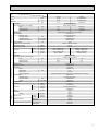
Service Ref.
Item
Function
Btu/h
W
kW
Capacity
Total input
Service Ref.
Power supply(phase, cycle,voltage)
Input
Running current
Starting current
External finish
Heat exchanger
Fan(drive) x No.
Fan motor output
Airflow(Low-High)
External static pressure
Booster heater
Operation control & Thermostat
Noise level(Low-High)
Cond. drain conn. O.D.
kW
A
A
REFRIGERANT
PIPING
kW
K/ min (CFM)
Pa(mmAq)
kW
W
D
H
Weight
Service Ref.
Power supply (phase, cycle, voltage)
Input
Running current
Starting current
External finish
Refrigerant control
Compressor
Model
Motor output
Starter type
Protection devices
Heat exchanger
Fan(drive) x No.
Fan motor output
Airflow
Defrost method
Noise level
Dimensions
Weight
Refrigerant
Charge
Cooling
42,300
12,400
4.49
Heating
45,700[56,000]
13,400[16,400]
4.44[7.44]
PLH-5GK(H)SB1.UK
Single, 50Hz, 220-240V
INDOOR UNIT
OUTDOOR UNIT
Dimensions
PLH-5GK(H)SB1.UK
dB(A)
mm,(in)
mm,(in)
mm,(in)
mm,(in)
kg,(lbs)
kW
A
A
kW
kW
K/ min (CFM)
W
D
H
dB(A)
mm,(in)
mm,(in)
mm,(in)
kg,(lbs)
kg,(lbs)
mm,(in)
Liquid
Pipe size O.D.
mm,(in)
Gas
Indoor side
Connection method
Outdoor side
Height difference
Between the indoor & outdoor units
Piping length
0.28
0.28[3.28]
1.27
1.27[13.8]
1.50
1.50[14.0]
Galvanized sheets with gray heat insulation
Plate fin coil
Turbo fan (direct) x 2
0.050+0.050
24-33(850-1165)
0(direct blow)
[3.0]
Remote controller & built-in
36-43
30(1-1/4)
UNIT : 1340(52-3/4)
PANEL : 1470(57-7/8)
UNIT : 820(32-1/4)
PANEL : 950(37-3/8)
UNIT : 258(10-1/8)
PANEL : 65(2-9/16)
UNIT : 45(99)
PANEL :10(22)
PUH-5YKSA2.UK
3, 50Hz, 380-415V(4wire)
4.21
4.16
6.89
6.81
53
53
Munsell 5Y 7/1
Capillary tube
Hermetic
ZR61K3-TFD
3.5
Line start
Internal thermostat, Anti-phasa protector, Thermal switch, HP switch
Plate fin coil
Propeller (direct) x2
0.085+0.085
95(3550)
Reverse cycle
55
970(38-3/16)
345+24(13-9/16 add 1)
1258(49-1/2)
114(251)
R-22
5.4(11.9)
9.52(3/8)
19.05(3/4)
Flared
Flared
Max. 50m
Max. 50m
9
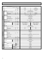
Service Ref.
Item
Function
Btu/h
W
kW
Capacity
Total input
Service Ref.
Power supply(phase, cycle,voltage)
Input
Running current
Starting current
External finish
Heat exchanger
Fan(drive) x No.
Fan motor output
Airflow(Low-High)
External static pressure
Booster heater
Operation control & Thermostat
Noise level(Low-High)
Cond. drain conn. O.D.
kW
A
A
REFRIGERANT
PIPING
10
kW
K/ min (CFM)
Pa(mmAq)
kW
W
D
H
Weight
Service Ref.
Power supply (phase, cycle, voltage)
Input
Running current
Starting current
External finish
Refrigerant control
Compressor
Model
Motor output
Starter type
Protection devices
Heat exchanger
Fan(drive) x No.
Fan motor output
Airflow
Defrost method
Noise level
Dimensions
Weight
Refrigerant
Charge
Cooling
46,100
13,500
5.03
Heating
54,300[64,500]
15,900[18,900]
4.88[7.88]
PLH-6GK(H)SB1.UK
Single, 50Hz, 220-240V
INDOOR UNIT
OUTDOOR UNIT
Dimensions
PLH-6GK(H)SB1.UK
dB(A)
mm,(in)
mm,(in)
mm,(in)
mm,(in)
kg,(lbs)
kW
A
A
kW
kW
K/ min (CFM)
W
D
H
dB(A)
mm,(in)
mm,(in)
mm,(in)
kg,(lbs)
kg,(lbs)
mm,(in)
Liquid
Pipe size O.D.
mm,(in)
Gas
Indoor side
Connection method
Outdoor side
Height difference
Between the indoor & outdoor units
Piping length
0.30
0.30[3.30]
1.36
1.36[13.9]
1.50
1.50[14.0]
Galvanized sheets with gray heat insulation
Plate fin coil
Turbo fan (direct) x 2
0.050+0.050
25-35(880-1235)
0(direct blow)
[3.0]
Remote controller & built-in
38-45
30(1-1/4)
UNIT : 1340(52-3/4)
PANEL : 1470(57-7/8)
UNIT : 820(32-1/4)
PANEL : 950(37-3/8)
UNIT : 258(10-1/8)
PANEL : 65(2-9/16)
UNIT : 45(99)
PANEL :10(22)
PUH-6YKSA2.UK
3, 50Hz, 380-415V(4wire)
4.73
4.58
7.74
7.50
74
74
Munsell 5Y 7/1
Capillary tube
Hermetic
ZR68KC-TFD
4.0
Line start
Internal thermostat, Anti-phasa protector, Thermal switch, HP switch
Plate fin coil
Propeller (direct) x2
0.10+0.10
100(3530)
Reverse cycle
56
970(38-3/16)
345+24(13-9/16 add 1)
1258(49-1/2)
117(258)
R-22
5.0(11.0)
9.52(3/8)
19.05(3/4)
Flared
Flared
Max. 50m
Max. 50m
4
DATA
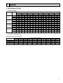
1. PERFORMANCE DATA
1) COOLING CAPACITY
Outdoor intake air DB°C
Indoor
Service Ref.
intake air
20
25
30
35
40
50
45
52
WB°C
CA
P.C.
CA
P.C.
CA
P.C.
CA
P.C.
CA
P.C.
CA
P.C.
CA
P.C.
CA
P.C.
16
7,768
2.65
7,555
2.77
7,278
2.98
6,983
3.19
6,671
3.41
6,342
3.62
5,995
3.84
5,852
3.93
18
8,271
2.71
8,053
2.82
7,760
3.05
7,452
3.27
7,130
3.49
6,793
3.72
6,442
3.94
6,293
4.03
20
8,779
2.76
5,573
2.88
8,267
3.11
7,948
3.35
7,616
3.59
7,270
3.83
6,912
4.07
6,765
4.17
22
9,293
2.81
9,115
2.94
8,799
3.18
8,470
3.43
8,128
3.69
7,773
3.96
7,405
4.23
7,254
4.35
16
9,786
2.77
9,518
2.89
9,168
3.11
8,797
3.34
8,404
3.56
7,989
3.79
7,552
4.02
7,371
4.11
18
10,419
2.83
10,145
2.95
9,775
3.18
9,388
3.42
8,982
3.65
8,558
3.89
8,115
4.12
7,927
4.22
20
11,060
2.88
10,800
3.01
10,414
3.25
10,012
3.50
9,594
3.75
9,159
4.00
8,707
4.26
8,522
4.36
22
11,707
2.94
11,482
3.07
11,085
3.32
10,670
3.59
10,240
3.86
9,792
4.14
9,329
4.43
9,138
4.54
16
12,510
3.60
12,167
3.75
11,720
4.04
11,245
4.33
10,771
4.62
10,249
4.91
9,654
5.21
9,423
5.33
18
13,319
3.67
12,969
3.83
12,496
4.13
12,001
4.44
11,497
4.74
10,964
5.04
10,374
5.35
10,134
5.47
20
14,138
3.74
13,806
3.91
13,313
4.22
12,799
4.54
12,266
4.87
11,720
5.19
11,131
5.53
10,894
5.66
22
14,965
3.81
14,679
3.98
14,170
4.31
13,640
4.65
13,078
5.00
12,516
5.36
11,925
5.74
11,682
5.90
16
13,619
4.03
13,246
4.20
12,760
4.53
12,243
4.85
11,726
5.18
11,159
5.51
10,511
5.84
10,259
5.97
18
14,501
4.11
14,119
4.29
13,605
4.63
13,065
4.97
12,517
5.31
11,937
5.65
11,294
5.99
11,033
6.13
20
15,392
4.19
15,031
4.37
14,494
4.73
13,935
5.09
13,355
5.45
12,759
5.82
12,118
6.19
11,860
6.34
22
16,293
4.27
15,981
4.46
15,427
4.83
14,851
5.21
14,238
5.60
13,626
6.01
12,983
6.43
12,718
6.60
PLH-3GK(H)B1.UK
PLH-4GK(H)SB1.UK
PLH-5GK(H)SB1.UK
PLH-6GK(H)SB1.UK
Note C A :Capacity (W)
P.C.:Power consumption (kW)
Cooling capacity correction factors
Service Ref.
PLH-3GK(H)B1.UK
PLH-4GK(H)SB1.UK
PLH-5GK(H)SB1.UK
PLH-6GK(H)SB1.UK
5m
1.00
1.00
1.00
1.00
10m
0.981
0.989
0.981
0.975
15m
0.968
0.980
0.968
0.955
Refrigerant piping length(one way)
35m
30m
25m
20m
0.913
0.925
0.940
0.952
0.940
0.950
0.960
0.970
0.913
0.925
0.940
0.952
0.884
0.900
0.918
0.935
40m
0.900
0.930
0.900
0.869
45m
0.886
0.920
0.886
0.855
50m
0.874
0.910
0.874
0.840
11
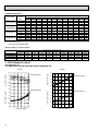
2) HEATING CAPACITY
Service Ref.
PLH-3GK(H)B1.UK
PLH-4GK(H)SB1.UK
PLH-5GK(H)SB1.UK
PLH-6GK(H)SB1.UK
Indoor
intake air
WB°C
15
20
25
15
20
25
15
20
25
15
20
25
-10
CA
5,752
5,508
5,293
7,122
6,820
6,554
9,177
8,787
8,444
10,889
10,426
10,020
-5
P.C.
2.11
2.28
2.42
2.35
2.54
2.69
3.03
3.26
3.46
3.33
3.59
3.81
P.C.
2.34
2.52
2.68
2.60
2.80
2.99
3.35
3.61
3.85
3.68
3.97
4.23
CA
6,593
6,334
6,077
8,163
7,842
7,524
10,517
10,104
9,694
12,479
11,989
11,502
Outdoor intake air DB°C
0
5
CA
P.C.
CA
8,516
2.57
7,514
8,198
2.77
7,231
7,895
2.97
6,944
10,543
2.86
9,303
10,150
3.09
8,953
9,774
3.30
8,597
13,584
3.69
11,987
13,078
3.97
11,535
12,594
4.25
11,077
16,119
4.05
14,224
15,518
4.37
13,687
14,943
4.67
13,144
10
P.C.
2.83
3.04
3.26
3.14
3.39
3.63
4.05
4.36
4.67
4.45
4.79
5.13
CA
9,595
9,235
8,928
11,880
11,434
11,054
15,307
14,732
14,242
18,163
17,480
16,900
P.C.
3.09
3.33
3.57
3.44
3.70
3.97
4.43
4.77
5.11
4.86
5.24
5.62
15
CA
10,752
10,340
10,044
13,312
12,802
12,435
17,152
16,494
16,022
20,352
19,572
19,011
P.C.
3.37
3.63
3.89
3.75
4.04
4.33
4.83
5.20
5.57
2.30
5.71
6.13
Note C A :Capacity (W)
P.C.:Power consumption (kW)
Heating capacity correction factors
Service Ref.
PLH-3GK(H)B1.UK
PLH-4GK(H)SB1.UK
PLH-5GK(H)SB1.UK
PLH-6GK(H)SB1.UK
5m
1.00
1.00
1.00
1.00
15m
1.00
1.00
1.00
1.00
10m
1.00
1.00
1.00
1.00
20m
1.00
1.00
1.00
1.00
Refrigerant piping length(one way)
35m
30m
25m
0.998
1.00
1.00
0.998
1.00
1.00
0.998
1.00
1.00
0.998
1.00
1.00
45m
0.993
0.993
0.993
0.993
40m
0.995
0.995
0.995
0.995
50m
0.990
0.990
0.990
0.990
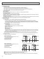
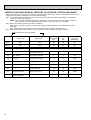
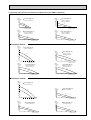
2. PERFORMANCE CURVE
PLH-3GK(H)B1.UK
PLH-4GK(H)SB1.UK/PLH-5GK(H)SB1.UK/PLH-6GK(H)SB1.UK
Cooling
Heating
1.4
1.2
1.0
22
20
18
16
0.8
TOTAL INPUT (RATIO)
1.2
1.0
0.8
1.4
22
20
18
16
1.2
1.0
0.8
0.6
0.4
-5
15
20
25 INDOOR DB (°C)
0.6
0.6
1.4
12
CAPACITY (RATIO)
INDOOR WB(°C)
5
15
25 35 46
OUTDOOR DB(°C)
INDOOR WB(°C)
TOTAL INPUT (RATIO)
CAPACITY (RATIO)
1.4
25
20
15
1.2
1.0
0.8
0.6
0.4
-12-10
-5
0
5
10 15
OUTDOOR WB(°C)
INDOOR DB (°C)
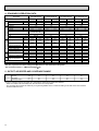
3. ELECTRICAL DATA
Indoor unit … 220V 50Hz 1phase
Outdoor unit…220V 50Hz 1phase / 380V 50Hz 3phase
PLH-3GK(H)B1.UK
PLH-4GK(H)SB1.UK
PLH-5GK(H)SB1.UK
PLH-6GK(H)SB1.UK
Mode
Cool
Cool
Cool
Cool
Capacity (W)
7,500
Total Input (kW)
3.29
Input (kW)
0.16
Current (A)
0.72
Starting current (A)
1.0
Input (kW)
Current (A)
Starting current (A)
3.13
14.67/5.23
54/34
Outdoor
Indoor
Service Ref.
Heat
8,200
[9,950]
3.08
[4.83]
0.16
[1.91]
0.72
[8.7]
1.0
[9.0]
2.92
13.68/4.88
54/34
9,500
3.43
0.26
1.18
1.5
3.17
5.29
37
Heat
10,200
[12,400]
3.42
[5.62]
0.26
[2.46]
1.18
[11.2]
1.5
[11.5]
3.16
5.28
37
12,200
4.47
0.28
1.27
1.5
4.19
7.32
49
Heat
13,100
[15,620]
4.41
[6.93]
0.28
[2.80]
1.27
[12.7]
1.5
[13.0]
4.13
7.21
49
13,300
4.94
0.30
1.36
1.5
4.64
8.10
68
Heat
15,500
[18,020]
4.86
[7.38]
0.30
[2.82]
1.36
[12.8]
1.5
[13.0]
4.56
7.96
68
Indoor unit … 230V 50Hz 1phase
Outdoor unit…230V 50Hz 1phase / 400V 50Hz 3phase
PLH-3GK(H)B1.UK
PLH-4GK(H)SB1.UK
PLH-5GK(H)SB1.UK
PLH-6GK(H)SB1.UK
Mode
Cool
Cool
Cool
Cool
Capacity (W)
7,600
Total Input (kW)
3.30
Input (kW)
0.16
Current (A)
0.72
Starting current (A)
1.0
Input (kW)
Current (A)
Starting current (A)
3.14
14.22/5.21
56/36
Outdoor
Indoor
Service Ref.
Heat
8,300
[10,200]
3.09
[4.99]
0.16
[2.06]
0.72
[9.0]
1.0
[9.3]
2.93
13.27/4.86
56/36
9,600
3.45
0.26
1.18
1.5
3.19
5.23
39
Heat
10,300
[12,700]
3.44
[5.84]
0.26
[2.66]
1.18
[11.6]
1.5
[11.9]
3.18
5.22
39
12,300
4.48
0.28
1.27
1.5
4.20
7.05
51
Heat
13,250
[16,010]
4.43
[7.18]
0.28
[3.03]
1.27
[13.2]
1.5
[13.5]
4.15
6.97
51
13,400
4.99
0.30
1.36
1.5
4.69
7.87
71
Heat
15,700
[18,450]
4.87
[7.62]
0.30
[3.05]
1.36
[13.3]
1.5
[13.5]
4.57
7.67
71
Indoor unit … 240V 50Hz 1phase
Outdoor unit…240V 50Hz 1phase / 415V 50Hz 3phase
PLH-3GK(H)B1.UK
PLH-4GK(H)SB1.UK
PLH-5GK(H)SB1.UK
PLH-6GK(H)SB1.UK
Mode
Cool
Cool
Cool
Cool
Capacity (W)
7,700
Total Input (kW)
3.31
Input (kW)
0.16
Current (A)
0.72
Starting current (A)
1.0
Input (kW)
Current (A)
Starting current (A)
3.15
13.82/5.16
58/37
Outdoor
Indoor
Service Ref.
Heat
8,400
[10,500]
3.10
[5.20]
0.16
[2.26]
0.72
[9.5]
1.0
[9.8]
2.94
12.89/4.81
58/37
9,700
3.46
0.26
1.18
1.5
3.20
5.24
40
Heat
10,400
[13,000]
3.45
[6.05]
0.26
[2.86]
1.18
[12.0]
1.5
[12.3]
3.19
5.22
40
12,400
4.49
0.28
1.27
1.5
4.21
6.89
53
Heat
13,400
[16,400]
4.44
[7.44]
0.28
[3.28]
1.27
[13.8]
1.5
[14.0]
4.16
6.81
53
13,500
5.03
0.30
1.36
1.5
4.73
7.74
74
Heat
15,900
[18,900]
4.88
[7.88]
0.30
[3.30]
1.36
[13.9]
1.5
[14.0]
4.58
7.50
74
13
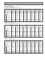
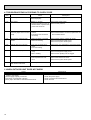
4. STANDARD OPERATION DATA
PLH-3GK(H)B1.UK
Service Ref.
Outdoor Indoor
side
side
Refrigeran circuit
Electrical circuit
Total
Mode
Cooling
Heating
7,700
8,400
3.31
3.10
PLH-3GK(H)B1.UK
1,50
V
240
0.72
0.72
A
PUH-3VKA2.UK
Outdoor unit Service Ref.
PUH-3YKA2.UK
Phase,Hz
1/3,50
Volts
V
240/415
Amperes
A
13.82/5.16 12.89/4.81
MPa·G
1.86
2.06
Discharge pressure
(kgf/F·G)
(18.9)
(21.0)
Capacity
Input
Indoor unit Service Ref.
Phase,Hz
Volts
Amperes
Suction pressure
Discharge temperature
Condensing temperature
Suction temperature
Ref. pipe length
Intake air temperature
Discharge air temperature
Intake air temperature
W
kW
PLH-4GK(H)SB1.UK
PLH-5GK(H)SB1.UK
PLH-6GK(H)SB1.UK
Cooling
Heating
9,700
10,400
3.46
3.45
PLH-4GK(H)SB1.UK
1,50
240
1.18
1.18
Cooling
Heating
12,400
13,400
4.49
4.44
PLH-5GK(H)SB1.UK
1,50
240
1.27
1.27
Cooling
Heating
13,500
15,900
5.03
4.48
PLH-6GK(H)SB1.UK
1,50
240
1.36
1.36
PUH-4YKSA2.UK
PUH-5YKSA2.UK
PUH-6YKSA2.UK
3,50
415
3,50
415
3,50
415
5.24
1.80
(18.4)
5.22
1.61
(16.4)
6.89
1.88
(19.2)
6.81
1.88
(19.2)
7.74
1.76
(18.0)
7.50
1.79
(18.3)
MPa·G
(kgf/F·G)
0.46
(4.69)
0.34
(3.47)
0.53
(5.41)
0.36
(3.67)
0.48
(7.96)
0.37
(3.77)
0.46
(4.69)
0.37
(3.77)
°C
°C
°C
m
DB°C
WB°C
DB°C
DB°C
WB°C
88.0
53.5
4.6
5
27
19
12.6
35
24
0.67
0.24
83.4
—
-2.8
5
20
15
42.9
7
6
—
—
74.2
48.3
8.1
5
27
19
14.7
35
24
0.78
0.15
69.8
—
-1.3
5
20
15
36.5
7
6
—
—
79.7
49.8
5.1
5
27
19
13.2
35
24
0.74
0.13
83.8
—
-1.4
5
20
15
42.3
7
6
—
—
78.4
46.9
4.4
5
27
19
12.4
35
24
0.70
0.11
81.3
—
-1.0
5
20
15
42.9
7
6
—
—
The unit of pressure has been changed to Mpa based on the international SI system.
F·G)
The conversion factor is : 1(Mpa·G)=10.2(kgf/F
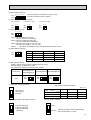
5. OUTLET AIR SPEED AND COVERAGE RANGE
Standard
Air flow
Air speed
Coverage rangem
K/s
m/W
m
PLH-3GK(H)B1.UK
18
5.3
6.5
PLH-4GK(H)SB1.UK
32
5.2
8.5
PLH-5GK(H)SB1.UK
33
5.4
8.7
PLH-6GK(H)SB1.UK
35
5.7
9.0
wThe air coverage range is the value up to the position where the air speed is 0.25m/sec.
When air is blown out horizontally from the unit at the Hi notch position.
The coverage range should be used only as a general guideline since it varies according to the size of the room and the
furniture inside the room.
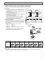
14
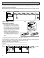
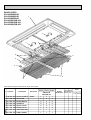
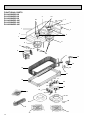
Wiring arrangement
opening side
(Ckanged by 90 )
Intake grille opening/
closing side(Factory setting)
Refrigerant piping side
High efficiency
filter(option)
65(2-9/16)<135(5-5/16)>
363(14-9/32)<433(17-1/16)>
175(6-7/8)<245(245(9-21/32)>
55(2-5/32)
35(1-3/8)
A
O
X
Changed by 90°
Changed by 180°
Intake gnill
flared connection 5/8F
220(8-21/32)
250(9-27/32)
62(2-7/16)
<Table 1>
O
Intake air filter
Ceiling side
Refrigerant piping side
X
A
72
2)
/3
27
(2
Vane motor
Wiring arrangement
opening side
950(23-1/8)
587(23-18)
<Air outlet hole>
80(3-5/32)
587(23-1/8)
<Air intake hole>
300(11-13/16)
61 104 104
820(32-9/32)
61
TERMINAL BLOCK
TERMINAL BLOCK h)
t
ng
le
g
n
)
rti
16 nse
3/
i
1- ipe )
(
30 n p 3/8
i
ra (22)
(D 60
/3
19
(2
66
Suspension bolt pitch
785(30-29/32)
890(35-1/32)Ceiling hole
192(7-9/16)
Branch duct hole (knock out hole)
Inspection hole
(drain water lift-up mechanism)
75(2-15/16)
160(6-5/16)
30(1-3/16)
Wiring arrangement
opening
Refrigerant pipe (9.52mm dia.)
flared connection 3/8F
Refrigerant pipe(15.88mmdia.)
Drain pipie VP-25
connection
Intake grille opening/
ciosing side
(Factory setting)
45(1-25/32)
30(1-3/16)
wNote that the space between the ceiling
panel of the unit and ceiling slab must be
10 to 15mm to be left.
Suspension boltM10
or W3/8
192(7-9/16)
820(32-9/32)
Grill
12- 2.8
Bar ring hole
5
530(20-7/8)
950(37-13/32)
110
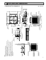
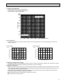
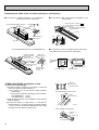
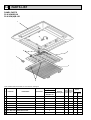
1. For drainage piping use VP-25 PVC piping.
2. For suspension bolts use M10 or W3/8 screws.
3. Figure 890X890 ceiling holes are standard but the ceiling holes for
860X860-910X910 can also be installed.
4. If installing the optional high efficiency filter element (filter casement),the
dimension between the transom and ceiling should be more than
365mm.
5. If installing the optional fresh air intake casement, the dimension
between the transom and ceiling should be more than 435mm.
6. The intake grill and its air filter´s opening /closing direction can be
changed. See table 1.
<Dimensions inside parentheses apply to installing the optional fresh air
intake casement.>
53(2-3/32)
Air intake grill
4-Auto vane
45
Suspension bolt pitch
70-85
Suspension bolt
lower edge
80(3-5/32)
53 (2-3/32)
190
25
Note
587(23-1/8)
<Air outlet hole>
100
30(1-3/16)
890(35-1/32)Ceiling hole
30(1-3/16)
192(7-9/16)
192(7-9/16)
65
65
587(23-1/8)
<Air outlet hole>
1. INDOOR UNIT PLH-3GK(H)B1.UK
w298(11-23/32)
5
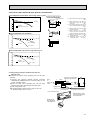
OUTLINES AND DIMENSIONS
Unit : mm (inch)
15
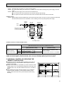
Inspection hole
(drain water lift-up mechanism)
75(2-15/16)
Refrigerant pipe (9.52mm dia.)
flared connection 3/8F
O
X
flared connection 3/4F
Refrigerant pipe(19.05mmdia.)
55(2-5/32)
35(1-3/8)
A
O
Changed by 180°
Drain pipie VP-25
connection
X
62(2-7/16)
Changed by 90°
Intake air filter
160(6-5/16)
Intake gnill
65(2-9/16)<135(5-5/16)>
363(14-9/32)<433(17-1/16)>
45(1-25/32)
175(6-7/8)<245(245(9-21/32)>
<Table 1>
250(9-27/32)
High efficiency
filter(option)
220(8-21/32)
192(7-9/16)
61
Refrigerant piping side
Ceiling side
Vane motor
Wiring arrangement
opening side
300(11-13/16)
7 104(=728)
Leave this bar ring hole.
Do not peel off
the insulation here.
1107(43-19/32)
<Air outlet hole>
1470(57-7/8)
61
22- 2.8
Bar ring hole
80
wNote that the space between the ceiling
panel of the unit and ceiling slab must be
10 to 15mm to be left.
Suspension boltM10
or W3/8
192(7-9/16)
30(1-3/16)
53
4-Auto vane
Grill
Intake grill opening/
closing side(Factory setting)
Air intake grill
442(17-13/32)
410(16-5/32)
1107(43-19/32)
<Air intake hole>
410(16-5/32)
104
1340(52-3/4)
TERMINAL BLOCK
TERMINAL BLOCK h)
t
ng
le
g
)
tin
16 ser
3/
2)
1- e in
(
/3
30 pip /8) -19
3
n
i 2
ra (2 66(
(D 60
Branch duct hole (knock out hole)
A
-
(3
77
2)
3
1/
Ceiling hole
1305(51-3/8)
Suspension bolt pitch
1410(55-1/2)
192(7-9/16)
30(1-3/16)
Wiring arrangement
opening
530(20-7/8)
950(37-13/32)
100
Suspension bolt pitch
70-85
Suspension bolt
lower edge
587(23-1/8)
<Air outlet hole>
80(3-5/32)
53 (2-3/32)
65
65
30(1-3/16)
30(1-3/16)
820(32-9/32)
890(35-1/32)Ceiling hole
5
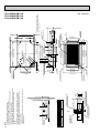
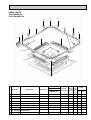
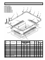
1. For drainage piping use VP-25 PVC piping.
2. For suspension bolts use M10 or W3/8 screws.
3. Figure 890X1,410 ceiling holes are standard but the ceiling holes for
860X1,380-910X1,430 can also be installed.
4. If installing the optional high efficiency filter element (filter casement),the
dimension between the transom and ceiling should be more than
365mm.
5. If installing the optional fresh air intake casement, the dimension
between the transom and ceiling should be more than 435mm.
6. The intake grill and its air filter´s opening /closing direction can be
changed. See table 1.
<Dimensions inside parentheses apply to installing the optional fresh air
intake casement.>
45
192(7-9/16)
587(23-1/8)
190
110
25
Note
w298(11-23/32)
16
<Air outlet hole>
PLH-4GK(H)SB1.UK
PLH-5GK(H)SB1.UK
PLH-6GK(H)SB1.UK
Unit : mm (inch)
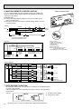
Unit : mm
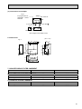
2. REMOTE CONTROLLER
FILTER
CHECK MODE
TEST RUN
TEST RUN
120
FILTER
CHECK MODE
18
130
83.5
Rear side wiring arrangement opening.
46
CAUTION
SW18
SW17
17
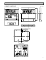
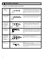
6
WIRING DIAGRAM
PLH-3GK(H)B1.UK/PLH-5GK(H)SB1.UK
PLH-4GK(H)SB1.UK/PLH-6GK(H)SB1.UK
I.B
TO
REMOCON
CN22
(WHT)
TRANSMISSION WIRES DC12V
R.B
TB5
X1
1 2 3
Showing fig: w 1
7 3
1
AC
11.3
V
3 1
CND
(WHT)
6 4 2 1
3 1
RT1
L
N
RT2
RED
BLU
GRN/YLW
H2
2. Since the indoor transformer (T)is connected with 240V power.if 220.230V
power is used. Change the wiring connection showing fig: w2.
3. Since the outdoor side electric wiring may change be sure to check the outdoor unit electric wiring for servicing.
230V
220V
240
230
220
YELLOW
ORANGE
RED
4. Indoor and outdoor connecting wires are made with polarities. make wiring
matching terminal numbers.
5. Symbols used in wiring diagram above are.
: Connector,
: Terminal block.
:PC board insertion tab.
5. Emergency operation
If a trouble occurs with either the remote controller or the indoor microcomputer no other truble exists. emergency operation for cooling or heating can
be performed by changing the setting of dip switch (SW3<I.B>) on the
indoor controller board.
(emergency dry operation is not possible.)
18
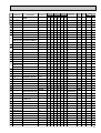
NAME
FAN MOTOR CAPACITOR
PROGRAM TIMER CONNECTOR
REMOTE SWITCH CONNECTOR
LOSSNAY CONNECTOR
CENTRALLY CONTROL CONNECTOR
DRAIN WATER LIFT-UP MECHANISM
DRAIN SENSOR
FUSE(6A)
FAN PHASE CONTROL
THERMAL FUSE
HEATER
DEW PREVENTION HEATER
INDOOR CONTROLLER BOARD
LIMIT SWITCH
FAN MOTOR (INNER THERMOSTAT)
VANE MOTOR
REMOTE CONTROLLER BOARD
ROOM TEMPERATURE THEARMISTOR
(0°C/15kΩ,25°C/5.4kΩ)
INDOOR COIL THEARMISTOR
(0°C/15kΩ,25°C/5.4kΩ)
C2
C1
3 2 1
For
PLH-4,5,6
2 4 3 1
3 2 1
MF1
321
GRILLE
3 2 1
MF1
BG79J990H03
TB2
fig w2
FAN1
(WHT)
5 3 1
MF2
NOTES :
1. Since the indoor fan motor (MF 1.2) is connected with 230~240V power. If
220V power is used. change the dip switch (SW5<1.B>)on the indoor controller board showing fig: w1.
SW5
SW5
fig w1
ON
ON
Indoor fan motor (MF1.2)for 220V.
OFF 1 2 3 4
OFF 1 2 3 4
When power supply is
MV
DS
1
BLK
WHT
RED
YLW
ORN
RED
DP
LS
POWER SUPPLY
w
(1 phase)
220-240V 50Hz
220V 60Hz
5 3 1
C1
T
F
VANE D HEATER
CNV
FAN1
(WHT)
(WHT)
6 2 5
BRN
2
3 1
AC
15.4
V
DRAIN-UP
CNP
(BLU)
WHT
RED
Showing fig:w3
(WHT)
BLK
GRY
3
CNT
BLK
WHT
WHT
RED
PIPE DRAIN
CN21 CN50
INTAKE (RED) (WHT) (WHT)
CN20
4 3 2 1
X4
X4
RED
1 2 3 4
FAN CON
VANE
POSITION
LOSSNAY
HEATER TRANS
CN2L
CN4T
CN23 CN24
(GRN) (YLW)
(RED)
BLK
1 2 3 4
SWA SWB
SWC
BLK
WHT
RED
1 2 3 4 5 6
ON
OFF
BLU
RED
RED
SW5
BLU
ON
OFF
SW6
YLW
1 2
SW2
BRN
SW3
4 3 2 1
RT2
ON
OFF
1 2 3
ZNR
X3
YLW
YLW
BLU
SW1
1 2 3 4 5 6 7 8 9 10
RED
YLW
SW7
1 2 3
TB4
TO OUTDOOR UNIT
CONNECTING WIRES
DC12V(polar)
SYMBOL
C1.2
CN1<R.B>
CN2<R.B>
CN2L<I.B>
CN51<I.B>
OP
DS
F<I.B>
F.C<I.B>
FS1.2
H1
H2
I.B
LS
MF1.2
MV
RB
RT1
ON
OFF
X3
1
1
RED
3 2
CN2
3 2
ON
OFF
6GK(H)SB
CENTRALLY
CONTROLL
CN51
HA
CN41
SW7
1 2 3
5GK(H)SB
X1
BRN
5 4
OFF
ON
1
MODELS
3GK(H)B
4GK(H)SB
5 3 1
BRN
SW17
2
B02
TB6
CN1
4321
87654321
2
FAN2
(WHT)
REMOCON
POWER
CN40
(WHT)
4 3 2 1
BLK
OFF
ON
1
OUT
DOOR
CN30
(WHT)
3 2 1
BLU
A01
SW18
fig: w 3
Indoor unit
BRN
ORN
YLW
Remote Controller
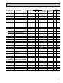
SYMBOL
SW1<I.B>
SW2<I.B>
SW3<I.B>
SW6<I.B>
SW5,7<I.B>
SWA<I.B>
SWB<I.B>
SWC<R.B>
SW17<I.B>
SW18<I.B>
T
TB2~5
X1<I.B>
X3<I.B>
X4<I.B>
ZNR
26H
88H
[Check items]
(1)Make sure that no other trouble exist the outdoor unit. Trouble with the outdoor unit prevents emergency operation.
(If any trouble exists the outdoor unit error code “P8”will be displayed on the
remote controller and the trouble position will be shown on the outdoor controller LED. See electric wiring diagram of the outdoor unit for details.)
(2)Make sure that there is no trouble with the indoor fan.
Emergency operation will be continuous run with power ON/OFF (ON/OFF
with the remote controller is not possible).
[Emergency operation procedure]
(1)Switch the fan connector on the indoor controller board from FAN 1 to FAN 2.
(2)Set the dip switch (SW3<I.B>) on the indoor controller board to 1 on and 2
off for cooling and 1 - 2 on for heating.
(3)Turn on the outdoor unit side circuit breaker, then the indoor unit side circuit
breaker.
(4)During emergency operation indoor fan runs at High speed but auto-vane
does not work.
(5)Thermostat will not function. Cold air belows out for defrosting during heating
thus do not operate defrosting for a long time.
(6)Emergency cooling should be limited to 10 hours maximum.
(The indoor unit heat exchanger may freeze).
(7)After every emergency operation, switch the fan connector to FAN1, and set
all dip switches (SW3<I.B>) to OFF.
NOTE: If the drain water lift up mechanism is identified to be defective with the
microcomputer doctor during cooling, do not use emergency operation
(it causes drain overflow)
NAME
MODE SELECTOR
ADDRESS SELECTOR
EMERGENCY OPERATION SWITCH
ADDRESS SELECTOR
MODEL SELECTOR
HIGH CEILING TYPE SWITCH
OUTLETS OF THE NUMBER OF DISCHERGE OUTRETS SWITCH
COMPATIBLE WITH OPTION SWITCH
ADDRESS SELECTOR
FUNCTION SELECTOR
TRANSFORMER
TERMINAL BLOCK
DRAIN WATER LIFT-UP MECHANISUM
DEW PREVENTION HEATER RELAY
VANE MOTOR RELAY
FAN MOTOR RELAY
VARISTOR
HEATER THERMAL SWITCH
HEATER CONNECTOR
7
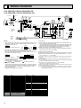
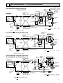
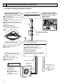
REFRIGERANT SYSTEM DIAGRAM
PLH-3GK(H)B1.UK/PUH-3VKA2.UK
PUH-3YKA2.UK
Refrigerant pipe
(option)
15.88mm( 5/8")
Ball valve
(with heat insulator) Strainer
Indoor unit
Unit : mm
Refrigerant flow in cooling
Control
Refrigerant flow in heating
high pressure
<R.V.coil>
switch
Heating ON
Protect high Pr.SW
Oil separator
Cooling OFF
Outdoor
unit
Service
4-way valve
port
Outdoor heat exchanger
Flexible tube
Indoor
heat
exchanger
Service
port
Thermistor
TH
Flared
connection
Strainer
Bypass
valve
Restrictor
valve
Accumulator
Restrictor
valve
Thermistor
RT2
Compressor
Distributor
with
strainer
O.D.4.0 o I.D.2.4 -r1,070
PUH-3
O.D.3.2 o I.D.2.0 -r400
Control
high pressure
switch
PLH-4GK(H)SB1.UK/PUH-4YKSA2.UK
Oil separator
Refrigerant pipe
Service
(option)
4-way valve
port
19.05mm([ 3/4") Ball valve
(with heat insulator) Strainer
Indoor unit
Outdoor unit
Outdoor heat exchanger
Protect
high Pr.
SW
Flexible tube
Indoor
heat
exchanger
Thermistor
TH3
Service
port
Restrictor
valve
Distributor
with
strainer
Capillary
tube
Restrictor
valve
Flared
connection
Strainer
Thermistor
RT2
Strainer
Refrigerant pipe Ball valve
(option)
(with service port)
9.52mm( 3/8")
(with heat insulator)
Capillary
tube
PLH-3
Capillary
tube
Bypass
valve
Accumulator
Capillary
tube
Compressor
Strainer
Ball valve
Refrigerant pipe
(option)
(with service port)
9.52mm([ 3.8")
(with heat insulator)
(O.D.3.2 o I.D. 2.0 -r820)X2
PUH-4
(O.D.3.2 o I.D. 2.0 -r250)
PLH-5GK(H)SB1.UK/PUH-5YKSA2.UK
PLH-6GK(H)SB1.UK/PUH-6YKSA2.UK
Control
Oil
high pressure
separator switch
Refrigerant pipe
Protect
(option)
4-way valve
Service high Pr.
19.05mm([ 3/4") Ball valve
port
(with heat insulator) Strainer
SW
Indoor unit
Outdoor unit
Outdoor heat exchanger
Flexible tube
Indoor
heat
exchanger
Thermistor
TH
Service
port
Strainer
Flared
connection
Thermistor
RT2
Accumulator
Restrictor valve
Distributor
with
strainer
Capillary
tube
PLH-5
PLH-6
Bypass
valve
Ball valve
Refrigerant pipe
(with service port)
(option)r
9.52mm([ 3/8")
(with heat insulator)
Compressor
Restrictor
valve
Capillary tube
Capillary tube
Thermal Switch
PUH-5
PUH-6
Strainer
(O.D.4.0 o I.D. 2.4 -r 840) o2
(O.D.4.0 o I.D. 2.4 -r1200) o2
O.D.4.0 o I.D.2.4 -r350
O.D.4.0 o I.D. 2.4 -r300
19
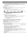
8
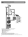
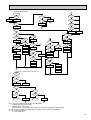
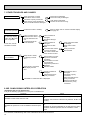
OPERATION FLOW-CHART
MAIN OPERATION
START
Power circuit
breaker
1
NO
YES
YES
Check SW
ON twice
NO
Operation SW
ON
w 1
YES
NO
“OFF” timer
YES
NO
NO
Set time
complete
“ON” timer
NO
YES
YES
YES
Set time
complete
w 2
NO
NO
Trouble
YES
STOP
Trouble STOP
PROTECTION DEVICE
SELF HOLD RELEASE
PROTECTION DEVICE
SELF HOLD
Remote controller
operation display
Operating mode
(COOL)
NO
Operating mode
(DRY)
w 3
Remote controller
trouble display
Remote controller
indicator lamp OFF
NO
Operating mode
(HEAT)
Indoor side
w 4
Fan STOP
NO
w 6
Operating mode
(FAN)
NO
Auxiliary heater OFF
YES
COOL operation
YES
DRY operation
YES
HEAT operation
YES
w 7
FAN operation
Auto COOL/HEAT
operation
Outdoor side
w 5
Compressor OFF
Fan STOP
Four-way valve OFF
w1 In addition, the centralized control and remote control can be operated.
w2 The modes which indicate the sources of trouble are listed below.
● EO-Signal transmitting/receiving error
● P1-Room temperature thermistor malfunction
● P2-Indoor coil thermistor malfanction
● P4-Drain sensor malfunction
● P5-Drain overflow
● P6-Coil frost/overheat protection
● P7-System error
● P8-Outdoor unit trouble
w3 The CHECK swich will show if an error has occurred in the past.
w4 Fan runs on low speed for 1 minute in order to remove overheat air.
w5 The 3-minute (6 minutes … heating mode) time-delay functions after compressor stops.
w6 FAN or AUTO mode is selected by the indoor dipswitch setting.
w7 In FAN mode, fan speed and vane operation depend on the remote controller setting. (Compressor is OFF.)
20
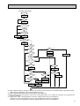
COOLING OPERATION
COOL operation
Four-way valve/OFF
NO
Initial
COOLING
YES
w8
Vane initial
setting
Vane
45 deg downward angle
60 deg downward angle
NO
YES
NO
Fan speed
LOW
YES
NO
Vane setting notch
Downward discharge
1 hour
YES
Vane horizontal
airflow
w9
NO
Compressor
thermostat
ON
YES
NO
Allowance
cancel
NO
YES
3-minute
time delay
YES
6-minute
time delay
NO
3-minute
compressor operation
NO
Allowance
period
NO
6 minute
time delay
NO
YES
Allowance set
w 10
Coil frost protection
YES
YES
Coil frost
prevention
NO
w 11
NO
Cooling area
YES
NO
10-minute
compressor operation
NO
YES
1 min continue
YES
Allowance cancel
FAN speed
LOW
Coil frost
protection
YES
NO
NO
Indoor coil
temperature is
10°C or higher
16-minute
compressor operation
YES
Indoor pipe
temperature is
1°C or lower
NO
Compressor ON
YES
YES
Coil frost
prevention
NO
FAN speed
LOW 5 min
elapse
NO
YES
Outdoor unit
trouble
3-minute
time delay
Coil frost
prevention release
Compressor OFF
1
w8 When operation stops or changes to cooling or dry mode, the auto vane turns to a horizontal angle. If operation changes
during auto vane SWING, the auto vane will continue to swing.
w9 When operating TEST RUN, the thermostat will be continuously ON.
w10After 3 minute compressor operation, if the indoor coil thermistor reads -15°C or below for 3 minutes, the compressor will
stop for 6 minutes.
w11Cooling area : Indoor coil temperature is more than 5 degrees above the room temperature.
Heating area : Indoor coil temperature is more than 5 degrees below the room temperature.
FAN area : Indoor coil temperature is within 5 degrees either way of the room temperature.
21
DRY OPERATION
DRY
operation
Four-way valve / OFF
NO
Initial dry
operation
w8
YES
Vane
setting notch
Vane initial setting
YES
Room tempereature is
18°C or lower
w12
NO
NO
During
compressor ON
YES
3-minute
compressor
operation
NO
NO
YES
NO
w9
Compressor &
thermostat ON
YES
Compressor &
thermostat
ON
NO
Compressor ON
time completes
10-minute
compressor
OFF
NO
YES
YES
w13
10-minute compressor
OFF timer start
Compressor ON
time set
Compressor OFF
Compressor ON
w14
w14
Fan speed LOW
1
w8—9 Refer to page 28~29.
w12
When room temperature is 18°C or below, the compressor cannot operate.
When room temperature rises over 18°C, the compressor starts after a 3-minute time delay.
w13
Compressor ON time is decided by room temperature. Refer to page 28~29.
w14
In dry operation, compressor ON makes the fan speed LOW and compressor OFF stops the fan.
It is not possible to set the fan speed with the remote controller
22
w9
NO
YES
Fan STOP
YES
3-minute
time delay
HEATING OPERATION
A
Heat operation
NO
initial
HEATING
w 11
Heating area
w 15
NO
Vane intial setting
Defrost release
NO
Outdoor unit trouble
NO
Indoor coil
thermistor is 60°C
or higher
NO
FAN speed
Low notti
NO
Four-way valve ON
1
YES
Hor adjust
in process
YES
Airflow 10% up
NO
FAN setting notch
YES
Compressor ON
YES
NO
10-minute
compressor
operation
YES
NO
YES
Compressor
thermostat ON
3 min.restart
prevention
YES
HOT adjust
6 min. elapse
B
Allowance cancel
6 min. restart
prevention
2
Indoor piping
-15°C or lower
w 11
YES
Heating
area
NO
Auxiliary heater
ON
NO
FAN STOP
Outdoor unit
trouble
FAN SPEED very low
NO
w 11
YES
Ariflow area
20 min.elaspe
Compressor ON
w 11
Compressor OFF
Airflow area
Heating area
NO
FAN SPEED
Low
NO
Auxiliary heater
thermostat ON
YES
YES
Indoor piping
60°C or higher
Auxiliary heater ON
FAN SPEED
Low 2 min.
elapse
YES
NO
FAN SPEED
setting nitch
Hot adjust
release
YES
Auxiliary heater OFF
NO
YES
FAN SPEED
Very low airflow
YES
NO
A
Hot adjust start
YES
B
YES
Indoor piping
55°C or lower
NO
Indoor piping
35°C or higher
NO
Allowance cancel
NO
NO
NO
2
YES
YES
3-minute
Auxiliary heater
OFF
NO
Defrost
30 min. elapse
defrosting
w9
NO
NO
YES
Vane setting notch
PLH-GKV
Type
YES
w 10
Outdoor unit
trouble
Overheat remote
START
NO
NO
Airflow area
Cooling area
NO
Indoor unit
70°C or higher
YES
YES
Defrost operation
START
Allowance
period
Four-way valve
OFF
YES
Overload protect
NO
6-minute restart
prevention
Allowance set
1
Compressor OFF
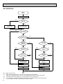
AUTOMATIC COOLING/HEATING OPERATION
Auto COOL/HEAT
operation
NO
1
w 16
Initial mode
w 17
YES
NO
T1 >
=T0
YES
COOL mode
COOL mode
HEAT mode
NO
YES
NO
NO
T1 < (T0 - 3)
YES
After 15min.
T1<(T0-2)
YES
YES
After 15min.
T1>(T0 + 2)
YES
NO
NO
COOL operation
T1>(T0 + 2)
HEAT operation
1
HEAT operation
Cool mode
set
1
w15 ( i ) Until Low airflow is set while in hot adjustment
( ii )While defrosting (FAN STOP)
(iii)When thermostat is OFF
In the case of( i ), (ii) and (iii) above, airflow is horizontal regardless the VANE setting.
w16 When AUTO operation is started, COOL or HEAT mode is selected automatically.
w17 T1 : Room temperature.
To : Set temperature
23
9
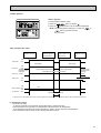
MICROPROCESSOR CONTROL
1. OUTLINE OF MICROPROCESSOR CONTROL
INPUT to remote controller
● OFF-ON switching.
● COOL/DRY-AUTO-HEAT selector switching.
● Thermostat setting.
● TIMER mode selector-switching and Timer
setting.
● HIGH-LOW fan speed switching.
● AUTO Vane selector (AIR DISCHARGE)
switching.
● TEST RUN switching.
● CHECK mode switching.
(Self diagnostic trouble shooting)
Remote controller board
● Processes and transmits
orders.
OUTPUT to remote controller
Remote controller
● LCD indicator
FILTER
CHECK MODE
TEST RUN
Indoor
unit
12VDC
Non-polar, two-wire cable
maximum length 500 meters
INPUT from indoor unit
● Room temperature thermistor (RT1)
● Indoor coil thermistor (RT2)
● Drain sensor
OUTPUT to indoor unit
Signal
Indoor controller board
● Receives orders from remote controller and
temperature data from indoor unit.
● Processes orders and data.
● Controls indoor and outdoor operation.
● Self diagnostic function.
w System control operation.
w Emergency operation.
w Set by dipswitch on indoor controller board.
● Transmits the power to remote controller.
● Compressor protection
device working
● Defrosting
START-STOP
● Fan speed control.
● Crankcase heater control
ON-OFF.
● Self diagnostic function
24
Outdoor unit
12VDC
Independent Control of
Outdoor Unit
Polar three-wire cable
1
2
3
OUTPUT to outdoor unit
1 2 3
● Autovane’s angle setting.
● Booster heater ON-OFF Control.
● Drain pump : ON-OFF.
● Emergency stop.
● Compressor and
outdoor fan : ONOFF
● Operation mode
change :COOLHEAT.
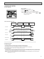
2. INDOOR UNIT CONTROL
2-1 COOL operation
<How to operate>
1 Press POWER ON/OFF button.
2 Press the
3 Press the
FILTER
CHECK MODE
button to display
TEMP button to set the desired temperature.
NOTE: Set temperature changes 1°C when the
button is pressed one time.
Cooling 19 to 30°C
TEST RUN
or
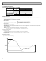
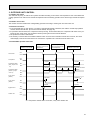
<COOL operation time chart>
Operation starts by
POWER button
ON.
Room temperature
becomes equal to
set temperature.
Room temperature
rises above set
temperature.
Operation stops by
POWER button
OFF.
ON
Thermostat
OFF
ON
Indoor fan
Auto vane
LOW or HIGH
LOW or HIGH
OFF
35°(SW5-3:OFF)
20°(SW5-3:ON)
discharge
position
Initally 35 degrees (SW5-3:OFF) or 20 degrees (SW5-3:ON) discharge
(Changeable by remote controller setting)
35°(SW5-3:OFF)
20°(SW5-3:ON)
discharge
position
3 minutes
Drain pump
ON
OFF
ON
Booster heater
OFF
ON
Compressor
OFF
OFF
Minimum 3 minutes
w1
w1 Even if the room temperature rise above the set temperature during this period, the compressor will not start until this period has ended.
(1) Compressor control
1 3-minute time delay
To prevent overload, the compressor will not start within 3 minutes after stop.
2 The compressor runs when room temperature is higher than set temperature.
The compressor stops when room temperature is equal to or lower than the set temperature.
3 The compressor stops in check mode or during protective functions.
4 Coil frost prevention
To prevent indoor coil frost, the compressor will stop when the indoor coil thermistor (RT2) reads 1°C or below after the
compressor has been continuously operated for at least 16 minutes or more. When the indoor coil temperature rises to
10°C or above, the compressor will start after a 3-minute time delay.
NOTE : By turning OFF the dipswitch SW1-5 on indoor controller board, the start temperature of coil frost prevention
changes from 1°C to -3°C.
25
5 Coil frost protection
When indoor coil temperatuer becomes -15°C or below,coil frost protection will proceed as follows.
<Start condition>
After the compressor has been continuously operated for 3 minutes or more,and the indoor coil temperature has been 15° or below for 3 minutes,the coil frost protection will start.
<Coil frost protection>
Compressor stops for 6 minutes,and then restarts.
lf the start condition is satisfied again during the first 10 minutes of compressor operation,both the indoor and outdoor
units stop,displaying a check code of“P8”on the remote controller.
<Termination conditions>
Coil frost protection is released when the start condition is not satisfied again during the allowance, or when the COOL
mode stops or changes to another mode.
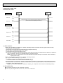
(2) Indoor fan control
Indoor fan speed LOW/HIGH depends on the remote controller setting.
However, if an outdoor unit abnormality is detected, the indoor fan speed will be LOW, regardless of the remote controller
setting.
When the outdoor unit abnormality detection is released and the fan speed returns to the set speed, the quiet cycle control
will work.
(a) Normal control
( i ) Fan speed LOW/HIGH depends on the remote controller setting regardless of the thermostat ON/OFF.
(ii) Fan speed will remain on LOW if an abnormality in outdoor unit is detected. (5 minutes)
When the abnormality detection is released, the fan speed returns to the set speed through the quiet cycle control.
(b)Quiet cycle control
To prevent noise due to a sudden rise in fan output,the fan output rise is controlled by 1 step per 1 second.
( i ) When the outdoor unit abnormality detection is released and the fan speed changes from LOW to the set speed,the
quiet cycle control will work.
5 minutes
SET
5 minutes
SET
LOW
LOW
OFF
1 Start-up of outdoor unit abnormality detection.
2 Release of outdoor unit abnormality detection.
3 Unit stop due to outdoor unit abnormality
with P8 indication.
NOTE 1 : Quiet cycle control does not work when the fan speed is lowered.
NOTE 2 : Fan stops immediately if the unit stops or the check mode is started.
NOTE 3 : During normal operation,except the above case,the fan speed changes immediately according to the remote
controller setting.
(c) Fluctuate operation
( i ) Start condition
●Turning ON the dipswitch SW1-2 enables the indoor fan to fluctuate by“SWING ON”command from the remote controller.
(i i ) Operation
●The fan output step changes by 1 step per 1 second in a 90-second cycle.
●The thermostat ON/OFF does not influence the fluctuate operation.
●When the fan speed is changed with the remote controller,the current output step will immediately change to the output step of the set speed. After,the fluctuate operation will restart from the initial value.
●lf an outdoor unit abnormality is detected,the indoor fan will run on LOW speed without a fluctuate operation.
After the abnormality is corrected,the fluctuate operation will restart from the initial value.
●When the unit stops running or enters the check mode,the indoor fan will turn OFF immediately.
(iii) Auto vane
The auto vane operates independently of the fluctuate operation. While the fluctuate operation is selected,the auto vane
is continuously ON.
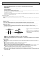
26
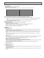
(3) Auto vane control
Auto vane position is set to 35degrees(SW5-3:OFF) or 20 degrees(SW5-3:ON) airflow at the start-up of COOL operation. It
can then be changed by the remote controller.
Auto vane operation can be changed between STOP mode (fixed operation) and SWINGmode by AIR DISCHARGE
SWING/STOP button on the remote controller.
(a) Stop mode (fixed operation)
( i ) At start-up of COOL operation, the auto vane is set to 10 degrees airflow direction.
( ii ) Airflow direction can be changed with
button.
1 Fan speed : LOW
35°/20°
55°/45°
65°/65°
SWING
(SW5-3:OFF/ON)
2 Fan speed : HIGH
35°/20°
55°/45°
45°/35°
65°/65°
SWING
(SW5-3:OFF/ON)
(b) SWING mode.
( i ) The vane motor turns ON when the SWING mode is selected.
The vane motor is continuously ON during SWING mode.
( ii ) The operation in SWING mode can be changed to the fluctuant operation by turning ON the dipswitch SW1-2.
(iii) When SWING mode is changed to STOP mode, the airflow direction returns to the position of the last STOP mode.
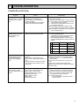
<AUTO RETURN>
1 Fan speed : LOW
35 /20
55 /45
AUTO RETURN
65 /65
AUTO RETURN
2 Fan speed : HIGH
35 /20
45 /35
55 /45
65 /65
When 55°/45 degrees or 65°/65 degrees airflow is selected with the LOW fan speed in COOL operation, “AUTO RETURN”
will appear below the temperature display. One hour later, the airflow direction returns to 35/25 degrees automatically and
“AUTO RETURN” will disappear. If the airflow direction is set to 35/20 degrees during “AUTO RETURN” indication, the
time counting for AUTO RETURN is cancelled.
27
<Auto vane drive>
(a) The auto vane is driven by a 2.5 rpm motor.
(b) Discharge direction can be selected between the No.1 and No.2 setting. (Initial setting is No.1)
Discharge direction
1
2
3
4
No.1
SW5-3 : OFF
35°
45°
55°
65°
No.2
SW5-3 : ON
20°
35°
45°
65°
(c) Vane motor drive time
Unit : sec
Discharge direction change
No.1 setting (SW5-3 : OFF)
No.2 setting (SW5-3 : ON)
50Hz
50Hz
Downward C → Horizontal 4→1
Rise → 3.3
Rise
Horizontal → Downward A 1→2
2.0
3.3
Downward A → Downward B 2→3
1.4
2.0
Downward B → Downward C 3→4
2.3
3.7
(d) Discharge direction is based on the horizontal position detected by the vane motor limit switch. When the horizontal
position can not be determined, the vane motor will remain ON until it is determined.
1 If the horizontal position still can not be detected, despite the 10minute detection, the vane motor will turn OFF.
Remote controller indication continues.
2 After, if the vane motor receives the “auto vane ON” command again, it will restart detecting the horizontal position.
If the horizontal position still can not be determined, despite the 10-minute detection, the vane motor will turn OFF.
(4) Detecting abnormalities in the outdoor unit
After the compressor has been continuously operated for 3 minutes, if the difference between the indoor coil temperature
and room temperature is out of RANGE C for 1 minute, the indoor fan speed will turn to LOW. Five minutes later, if the difference is still out of RANGE C,the outdoor unit is functioning abnormally. Thus, the compressor stops and check code
“P8” appears on remote controler.
RANGE A : Indoor coil temperature is more than 5 degrees above room temperature.
RANGE B : Indoor coil temperature is within 5 degrees either way of room temperature.
RANGE C : Indoor coil temperature is more than 5 degrees below room tempetature.
Indoor coil temperature
minus room temperature
(degree)
+5
RANGE A
0
RANGE B
-5
RANGE C
(5) Drain pump control
The drain pump works in COOL or DRY operation. When operation stops or changes to HEAT mode, the drain pump continues to operate for 3 more minutes. The drain pump does not work in check mode.
<Drain sensor>
When both the drain pump and unit are operating, the drain sensor detects the temperature. This temperature tells
whether the drain water level is above or under the drain sensor. If the drain water level rises above the drain sensor due
to a drain pump malfunction, the unit will stop operating in order to prevent drain from overflowing. The check code “P5” on
the remote controller will display this occurrence. When either of the following conditions are satisfied, the drain sensor is
determined to be under water.
● Though the drain sensor has been heated by the drain sensor heater for more than 40 seconds, its temperature rise is
less than 20 degrees.
● The drain sensor temperature is below 63°C.
(6) Dew prevention heater
To prevent dew from accumulating on the grill, the dew prevention heater is continuously ON during COOL operation.
It is independant of the thermostat ON/OFF.
28
2-2 DRY operation
<How to operate>
1 Press POWER ON/OFF button.
2 Press the
FILTER
CHECK MODE
button to display “
”
3 Press the
TEMP button to set the desired temperature.
NOTE: The set temperature changes 1°C when the
or
TEST RUN
button is pressed one time.
Dry 19 to 30°C
<DRY operation time chart>
Operation starts by
POWER button
ON.
Room temperature
becomes equal to
set temperature.
Room temperature
rises above set
temperature.
Operation stops by
POWER button
OFF.
ON
OFF
Thermostat
DRY MODE
DRY MODE
ON
Indoor fan
Auto vane
OFF
35°(SW5-3:OFF)
20°(SW5-3:ON)
discharge
position
Initally 35 degrees (SW5-3:OFF) or 20 degrees (SW5-3:ON) discharge
(Changeable by remote controller setting)
35°(SW5-3:OFF)
20°(SW5-3:ON)
discharge
position
3 minutes
Drain pump
ON
OFF
ON
Booster heater OFF
ON
Compressor
OFF
OFF
Minimum 3 minutes w1
w1 Even if the room temperature rises above the set temperature during this period, the compressor will not start until this period has ended.
(1) Compressor control
13-minute time delay
To prevent overload, the compressor will not start within 3 minutes after stop.
2The compressor runs when the room temperature is higher than the set temperature.
The compressor stops when the room temperature is equal to or lower than the set temperature.
3The compressor stops in check mode or during protective functions.
29
4The compressor will not start when the room temperature is below 18°C.
The compressor starts intermittent operation when the power is turned ON with room temperature above 18°C. The compressor ON/OFF time depends on the thermostat ON/OFF and the following room temperatures.After 3-minute compressor operation,
● If the room temperature thermistor reads above 28°C with thermostat ON, the compressor will operate for 6 more minutes and then stop for 3 minutes.
● If the room temperature thermistor reads 26°C~28°C with thermostat ON, the compressor will operate for 4 more minutes and then stop for 3 minutes.
● If the room themperature thermistor reads 24°C~26°C with thermostat ON, the compressor will operate for 2 more
minutes and then stop for 3 minutes.
● If the room temperature thermistor reads below 24°C with thermostat ON, the compressor will stop for 3 minutes.
● If the thermostat is OFF regardless of room temperature, the compressor will stop for 10 minutes.
5Coil frost protection
Coil frost protection in DRY operation is the same as in COOL operation.
6Coil frost prevention
Coil frost prevention does not operate in DRY operation.
(2) Indoor fan control
The indoor fan runs on LOW speed during compressor operation. The fan speed cannot be changed with the remote controller. Also, the indoor fan does not run during compressor OFF.
● The fluctuate operation will not work in DRY operation.
(a)During compressor OFF
● When the indoor coil temperature is 6°C or above, the indoor fan will stop.
● When the indoor coil temperature is below 6°C, the indoor fan will run in DRY mode.
(b)During compressor ON
● The indoor fan runs on EXTRA-LOW speed for the first 1 minute after the compressor is turned on.
● After, the indoor fan runs in DRY mode.
<Dry mode>
The fan notch is controlled by the indoor coil temperature every 30 seconds.
Indoor coil temperature
Below -10°C
Fan operation
LOW speed
-10 to 0°C
EXTRA-LOW speed
Above 0°C
Dry mode
During compressor OFF, when the indoor coil temperature becomes 6°C or above, the indoor fan turns OFF immediately.
(c)Quiet cycle control
from DRY mode to EXTRA-LOW speed.
The quiet cycle control works, when the indoor fan operation changes from DRY mode to LOW speed.
from EXTRA-LOW speed to LOW speed.
{
The quiet cycle control does not work when the fan speed is lowered.
(3) Auto vane & drain pump controls
Same as in COOL operation
(4) Detecting abnormalities in the outdoor unit
An abnormality in the outdoor unit can not be detected in DRY operation.
30
2-3 HEAT operation
<How to operate>
1 Press POWER ON/OFF button.
2 Press the
button to display “
FILTER
CHECK MODE
”
3 Press the
TEMP button to set the desired temperature.
NOTE: The set temperature changes 1°C when the
or
TEST RUN
button is pressed one time.
Heating 17 19 to 28°C
<Display in HEAT operation>
[DEFROST]
The [DEFROST] symbol is only displayed during the defrost operation.
[STANDBY]
The [STANDBY] symbol is only displayed from the time the heating
operation starts until the heated air begins to blow.
<HEAT operation time chart>
Operation starts by
POWER button
ON.
Room temperature
becomes equal to
set temperature.
Room temperature
falls below set temperature.
Operation stops by
POWER button
OFF.
ON
Thermostat
OFF
Extra LOW
ON
Indoor fan
LOW
Extra LOW w1
LOW or HIGH
LOW or HIGH
OFF
ON
Auto vane
1
Horizontal
Depends on remote
controller setting
Horizontal
w1 Changeable by indoor
dipswitch SW1- 7
and SW1- 8.
Depends on remote
controller setting
OFF
ON
Drain pump
OFF
OFF
ON
Booster heater
OFF
Hot adjustment
Hot adjustment
OFF during thermostat OFF
hot adjustment
defrosting
ON
Compressor
OFF
Minimum 3 minutes w2
ON
Power ON lamp
OFF
ON
STAND BY lamp
From POWER ON until
warm begins to blow
OFF
w2 Even if the room temperature falls below the set temperature during this period, the compressor will not start until this period has ended.
31
(1) Compressor control
13-minute time delay
To prevent overload, the compressor will not start within 3, minutes after stop.
2The compressor runs when the room temperature is lower than the set temperature.
The compressor stops when the room temperature is equal to or higher than the set temperature.
3The compressor stops in check mode or during protective functions.
4Overheat protection
<Start condition>
When the indoor coil thermistor reads 70°C or above, the overheat protection will start.
<Overheat protection>
The compressor stops for 6 minutes, and then restarts.
If the start condition is satisfied again within 10 minutes of compressor operation, both the indoor and outdoor units stop,
displaying a check code of “P6” on the remote controller.
<Termination conditions>
Overheat protection is terminated when the start condition is not satisfied again during the allowance (10-minute compressor operation), when operation mode changes to other mode, or when thermostat turns OFF.
(2) Indoor fan control
(a) Normal control
( i )The indoor fan runs on EXTRA-LOW speed during the thermostat OFF.
EXTRA-LOW speed can be changed to LOW or HIGH speed by setting the dipswitch SW1-7 and SW1-8.
If the indoor coil temperature becomes more than 5 degrees below the room temperature during the thermostat
OFF, the indoor fan will stop. After, when the indoor coil temperature becomes within 5 degrees of room temperature, the indoor fan will run on EXTRA-LOW speed.
( ii )Hot adjustment
Hot adjustment is a warm-up for HEAT operation
<Start conditions>
The hot adjustment works under any of the follwing conditions.
● HEAT operation starts.
● Defrosting ends.
● Thermostat turns ON.
[Hot adjustment]
Initially, the indoor fan runs on EXTRA-LOW speed. When 5 minutes have passed or the indoor coil temperature
exceeds 35°C, the fan speed changes to LOW. Two minutes later, the hot adjustment ends. Then, the fan speed
depends on the remote controller setting.
(iii)The indoor fan stops when the indoor coil temperature is within 5 degrees either way of room temperature.
(iv)To eliminate the remaining heat, the indoor fan runs for the first 1 minute after the booster heater is turned OFF.
(b) Quiet cycle control
( i )Quiet cycle control in hot adjustment
<Heating starts and thermostat returns ON>
1HEAT operation starts.
2lndoor coil temperature becomes 35°C or over,
or 5 minutes have passed.
32 minutes have passed.
4Thermostat turns OFF.
5Thermostat turns ON.
Set speed
Set speed
Low
Low
ExtraLow
ExtraLow
OFF
1
1HEAT operation starts.
2lndoor coil temperature becomes 35°C or over,
or 5 minutes have passed.
32 minutes have passed.
4Defrosting starts.
5Defrosting has ended.
2
3
4
5
2
<Heating starts and defrosting has ended. >
Set speed
Set speed
Low
Low
ExtraLow
ExtraLow
OFF
1
2
3
4
2
3
●The indoor fan runs on EXTRA-LOW speed at the start-up of HEAT operation.
●The indoor fan runs at a minimum air flow amount afaer defrosting.
●When the indoor coil temperature becomes 35°C or over during the quiet cycle control,the indoor fan speed will
change to LOW speed.
32
NOTE1:The quiet cycle control does not work when the fan speed is lowered.
The indoor fan stops immediately when the operation stops,except to eleminate the remaining heat.
NOTE2:When the fan speed is changed with the remote controller during the set speed operation,the fan speed will
change immediately.
(c) Fluctuant operation
The fluctuant operation will not work in HEAT operation.
(3) Auto vane control
Auto vane operation can be changed between STOP mode (fixed operation) and SWING mode by AIR DISCHRGE
SWING/STOP button on the remote controller.
(a) STOP mode (fixed operation)
( i ) The airflow direction at the start-up of HEAT operation is the same as that of the previous operation.
( ii ) The airflow direction can be charged by the remote controller setting.
35°/20°
45°/35°
55°/45°
65°/65°
SWING
(SW5-3 : OFF/ON)
In the following cases, airflow direction becomes 35°/20° regardless of the remote controller setting.
1 During the hot adjustment with fan speed at EXTRA-LOW
2 During defrosting with indoor fan OFF
3 During the thermostat OFF
(b) SWING mode
( i ) The vane motor turns ON when the SWING mode is selected.
The vane motor is continuously ON during SWING mode.
( ii ) When SWING mode is changed to STOP mode, the airflow direction returns to the position of the last STOP
mode.
( iii ) In the following cases, the discharge direction is 35°/20° regardless of the remote controller setting.
1 During the hot adjustment with fan speed at EXTRA-LOW
2 During defrosting with indoor fan OFF
3 During thermostat OFF
(4) Booster heater control (PLH-3GKHB1, PLH-4GKHSB1, PLH-5GKHSB1, PLH-6GKHSB1)
When the room temperature is 3 degrees below the set temperature, the booster heater will turn ON.
When the room temperature is equal to the set temperature, booster heater will turn OFF.
During the hot adjustment, the booster heater will not work.
<Overheat prevention>
When the indoor coil thermistor rises to 60°C or above, the booster heater cannot work.
When the indoor coil thermistor falls to 55°C or below, the booster heater can work.
(5) Detecting abnormalities in the outdoor unit
When the outdoor unit is determined to be abnormal by the following causes, the compressor will stop and the check code
“ P8 ” will appear on the remote controller display.
w1 (See the next page.)
1 During compressor ON after hot adjustment
1 If the difference between the indoor coil temperature and room temperature is in the RANGE B, the indoor fan will
stop.
2 Within 20 minutes after entering RANGE B (except for the first 10 seconds),
a) If the temperature difference enters RANGE A, the hot adjustment stasrts,
b) If the temperature difference is still in RANGE B, the outdoor unit is deemed abnormal.
c) If the temperature difference enters RANGE C, defrosting starts.
Within 20 minutes after entering RANGE C,
●If the temperature difference does not return to RANGE B,the outdoor unit is deemed abnormal.
●If the temperature difference returns to RANGE B, the next 20 minutes is an allowance period. If the difference enter
RANGE A during the allowance, defrosting ends and the hot adjustment starts. If the difference does not enter
RANGE A during the allowance, the outdoor unit is deemed abnormal.
2 During compressor ON in hot adjustment
After 20 minutes of defrosting in hot adjustment, if the temperature difference is still in RANGE C, the outdoor unit is
determined to be abnormal.
3 During compressor OFF
After 20 minutes of thermostat OFF, if the indoor coil thermistor reads -25°C or below, the outdoor unit is determined to
be abnormal.
33
(6) Indoor coil thermistor abnormality detection
An abnormality can be detected during compressor ON, except for the following.
●For the first 20 minutes after the temperature difference between the indoor coil temperature and room temperature
enters the RANGE C.
●When the temperature difference enters the RANGE C until it moves to the RANGE B.
(7) Defrosting operation
After the outdoor unit starts the defrosting operation, when the temperature difference beetween the indoor coil temperature and room temperature gets out of RANGE A and into RANGE B, the indoor unit starts the defrosting mode. After the
outdoor unit stops the defrosting operation, when the temperature difference returns to the RANGE A, the indoor unit stops
the defrosting mode. While the indoor unit is in the defrosting mode, the indoor fan and the booster heater stop.
w1 RANGE A : Indoor coil temperature is more than 5 degrees above room temperataure.
RANGE B : Indoor coil temperature is within 5 degrees either way of room temperature.
RANGE C : Indoor coil temperature is more than 5 degrees below room temperature
Indoor coil temperature
minus room temperature
(degree)
+5
RANGE A
0
RANGE B
-5
34
RANGE C
2-4 AUTO operation (Automatic COOL/HEAT change over operation)
<How to operate>
1 Press POWER ON/OFF button.
2 Press the
button to display “
FILTER
CHECK MODE
3 Press the
TEST RUN
”
TEMP button to set the desired temperature.
NOTE: The set temperature changes 1°C when the
or
button is pressed one time.
Automatic 19 to 28°C
●“AUTOMATIC” works to change by itself the operation
mode either to cooling or heating according to the room
temperature.
(1) Initial mode
1 When AUTO operation starts after unit OFF.
● If the room temperature is higher than the set temperature, operation starts in COOL mode.
● If the room temperature is equal to or lower than the set temperature, operation starts HEAT mode.
2 When AUTO operation starts after COOL or HEAT operation, the previous mode continues.
(2 ) Mode change
1 HEAT mode changes to cool mode when 15 minutes have passed since the room temperature became 2 degrees
above the set temperature.
2 COOL mode changes to HEAT mode when 15 minutes have passed since the room temperature became 2 degrees
below the set temperature.
To:Set temperature (19
(degree)
28
When room temperature becomes2degrees above the set temperature,the operation mode can not be changed
for 15 minutes.
)
Mode change (HEAT
COOL)
To + 2
To + 1
To
To - 1
To - 2
15 minutes
Start
15 minutes
Minimum 3 minutes
COOL mode
HEAT mode
Mode change
(COOL HEAT)
HEAT mode
ON
Compressor
OFF
Minimum 3 minutes
(3) Temperature range
AUTO operation is available under the outside air temperatures as follows.
-9
0
10
20
30
40
46
(Outside air temperature)
-5
-8.5
Cooling range
Heating range
35
2-5 Auto vane control
<How to operate>
To change the air flow direction, press
button.
FILTER
CHECK MODE
TEST RUN
NOTE: Discharge direction can be set by the indoor dipswitch SW5-3.
Dipswitch
1
2
3
4
SW5-3:OFF
35°
45°
55°
65°
SW5-3:ON
20°
35°
45°
65°
1 35 /20
2 45 /35 downward
3 55 /45 downward
Available in COOL operation with fan speed on HIGH or
in HEAT operation.
Unavailable in DRY operation.
If fan speed changes from LOW to HIGH during 45°/35°
downward airflow in COOL mode, the direction automatically changes to 35°/20°.
4 65 /65 downward
5 swing
Changes by pressing the
button.
(1) COOL/DRY operation
At the start-up of COOL or DRY operation, the airflow direction in automatically set to 35°/20°. After, it can be changed to
another direction with
button on the remote controller.
<Auto return>
When 55°/45° or 65°/65° airflow is set with fan speed in LOW, “AUTO RETURN” appears below the room temperature display. One hour later the direction changes to 35/20 degrees, automatically and “AUTO RETURN” disappears.
(2) HEAT operation
At the start-up of HEAT operation, airflow direction depends on the setting of the last operation.
After, it can be changed to another direction with
button. The airflow direction shifts to 35°/20° regardless of the
remote controller settings under any of the following conditions.
● Thermostat OFF
● Defrosting
● Indoor fan speed EXTRA-LOW in hot adjustment
36
2-6 TIMER operation
<Timer function>
AUTO STOP ·········The air conditioner stops after the set time lapses.
AUTO START ········The air conditioner starts after the set time lapses.
AUTO OFF ············Timer is not active.
<How to operate>
1. Press POWER ON/OFF button.
2. Press “ ” button to select AUTO STOP or AUTO START.
3. Press “
” button to set desired time.
Time setting is in 1 hour units for up to 24 hours.
Each time HOURS button is pressed, set time increases by 1 hour.
When HOURS button is pressed and held, the set time increases
by 1 hour every 0.5 seconds.
4. To cancel the timer operation, press POWER ON/OFF button.
FILTER
CHECK MODE
TEST RUN
<Timer setting example>
This setting will stop the air conditioner in 8 hours.
With the lapse of time, time display changes in 1 hour units, showing remaining time.
OFF
2-7 Test run
<Before test run>
● After installing, wiring, and piping the indoor and outdoor units, check for refrigerant leakage, looseness in power supply or
contorol wiring, and mistaken polarity.
● Use a 500-volt megger to check the resistance between the power supply terminal block and ground to make sure that it is
at least 1.0MΩ.
Attention:
Do not use the air conditioner if resistance is less than 1.0MΩ.
Remote controller
FILTER
1
Turn on main switch.12 hours before proceeding to step 2 to allow
for crankcase heater operation.
2
Push the TEST RUN button twice and indication of TEST RUN will
be shown on the liquid crystal display.
3
Press the
button to display
, COOL/DRY(or HEAT)to
confirm that cool (or warm) air is blown out.
(At heating operation, there may be a short delay before warm air
begins to blow out.)
4
Push
properly.
5
Check the operation of outdoor unit fans.This unit controls the rotation speed and performance capacity of fans.ln some cases,it may
rotate at low speed as the condition of outside air requires and the
speed will be kept unless the performance has become deficient.
Therefore,when the condition of outside air demands,there may be
such cases as the fan stops or rotates reversely.
Please note that these symptoms are not mulfunction.
6
After the check is finished leave the test run mode, push the power
ON/OFF button.
It can also be stopped by pushing the timer MODE button.
CHECK MODE
TEST RUN
TEST RUN button
TEST RUN Display
Indoor coil temperature code Display
*The above figure shows the state of TEST
RUN at cooling operation.
button LOW/HIGH to check that the fan speed changes
●When a TEST RUN is started,the timer shall be set to 2 hours. The unit will automatically turn off after 2 hours.
37
(1) Indoor coil temperature code
During the test run, the indoor coil temperature code from 1 to 15 is displayed on the remote controller instead of room
temperature. The code should fall with the lapse of time in normal COOL operation, and should rise in normal HEAT
operation.
Code
1
2
3
4
5
6
7
8
Indoor coil temperature
-40~1°C
~10°C
~15°C
~20°C
~25°C
~30°C
~35°C
~40°C
Code
9
10
11
12
13
14
15
Indoor coil temperature
~45°C
~50°C
~55°C
~60°C
~70°C
~90°C
Termistor abnormality
(2) Trouble during test run
● If the unit malfunctions during the test run, refer to section 10 in this manual entitled “TROUBLESHOOTING.”
● When the optional program timer is connected to the conditioner, refer to its operating instructions.
2-8 Emergency operation
When the remote controller or microprocessor malfunctions but all other parts are normal, emergency operation is started
by setting the dipswitch SW3 on the indoor controller board.
<Before emergency operation>
1. Make sure the compressor and the indoor fan are operating normally.
2. Locate the defect with the self-diagnostic function. When the self-diagnostic function indicates “protective function is
working”, release the protective function before starting the emergency operation.
CAUTION: When the self-diagnostic function indicates a check code of “P5” (drain pump malfunction), DO NOT start
the emergency operation because the drain may overflow.
<How to operate>
1. For emergency cooling, set the dipswitch SW3-1 to ON and SW3-2 to OFF.
For emergency heating, set the dipswitch SW3-1,2 to ON.
Emergency
cooling
1
1 ON
2
Emergency
heating
1
2
1.2 ON
Normal
operation
1
2
1.2 OFF
Microcessor board
2. Turn ON the outdoor unit breaker and then ON the indoor unit breaker.
Emergency operation will now start.
3. During emergency operation, the indoor fan operates on high speed, but the swing louvers and the auto vanes do not
operate.
4. To stop emergency operation, turn OFF the indoor unit breaker.
NOTE: The remote controller POWER ON/OFF button can not start/stop emergency operations.
CAUTION: Do not use emergency cooling for more than 10 hours, as the indoor coil may freeze.
38
2-9 Interlock with ventilation system (LOSSNAY)
Mr. SLIM/LOSSNAY interlock operation is available by using the optional parts listed below.
(1) System organization
Relay box (PZ-12RB-E)
Relay box
Mr. SLIM
LOSSNAY
LOSSNAY
Power supply
Mr. SLIM
Power
supply
Remote
controller
LOSSNAY control switch (PZ-05SLB2-E)
Remote display
adapter
(PAC-SA88HA-E)
Remote
controller
LOSSNAY control switch
(PZ-05SLB2-E)
(2) LOSSNAY models connectable to Mr. SLIM are: LGH-15RS-E, LGH-50RS-E
LGH-25RS-E, LGH-80RS-E
LGH-35RS-E, LGH-100RS-E
(3) Reqired parts are:
● Relay box (PZ-12RB-E)…Contact capacity 10A
● Remote display adapter (PAC-SA88HA-E)…An optional part for Mr. SLIM
● LOSSNAY control switch (PZ-05SLB2-E)…For LOSSNAY individual operation
(4) Operation
1LOSSNAY turns ON/OFF according to Mr. SLIM ON/OFF
2While Mr. SLIM is OFF, LOSSNAY individual operation is available by using the LOSSNAY control switch.
When Mr. SLIM turns OFF with the LOSSNAY control switch at ON, LOSSNAY will continue to operate.
(5) Wiring.
1When the LOSSNAY control switch is used
2When the LOSSNAY control switch is not used:
Mr. SLIM
Indoor controller
board
Remote
controller
Power supply
for Mr. SLIM
220 240V AC
Relay box
(PZ-12RB-E)
LOSSNAY
Terminal block
Terminal block
A
Connector
CN51
B
L
N
HIGH
N
GRN
YLW
ORN
RED
BRN
ORN
LOW
RED
10m
Insulation
is needed
Relay box
(PZ-12RB-E)
A
B
Connecting wire
0.13mm 2 or over
Connecting wire
solid wire,
1.6 or 2.0
(field supplied)
YLW
8
ORN
L
RED
N
WHT
HIGH
HIGH
RED
WHT
N
WHT
Mr.SLIM
CN51
12V DC
Circuit
breaker
2
5
RED
DAMPER
7
6
N
4
L
N
Power supply
220 240V AC
ORN
DAMPER
WHT
3
1
Circuit breaker
(field supplied)
L
Power
supply
N
50Hz
220 240V
LOSSNAY
Terminal
block
N
L
ORN
LOW
LOW
PL
HIGH
N HIGH
N
DAMPER
DAMPER
DAMPER
LOSSNAY control switch
(PZ-05SLB 2-E)
Junction box
(field supplied)
RED
WHT
RED
ORN
WHT
NOTE: For further information, refer to the
LOSSNAY technical & service manual.
39
2-10 Dip switch functions
Each figure shows the initial factory setting.
1. On remote controller board
(1) SW17(Address selector)
1 2 3 4 5 6 7 8
ON
OFF
SW17-1~6) For address setting
SW17-7) When two remote controllers are used,this switch sets the controller function.
OFF:The remote controller is set as a main controller.
ON:The remote controller is set as a sub controller.
SW17-8) Switch for system back-up (This switch is unavailable for PLH-GKHB.UK Keep this switch at OFF.)
OFF:Without back-up
ON:With back-up
(2) SW18(Function selector)
1 2 3 4
ON
OFF
SW18-1) Switch for timer
OFF:Single day ON:timer every day
SW18-2) Switch for filter sign
OFF:filter sign adsent
ON:filter sign present
SW18-3) Switch for filter sign time setting.
OFF:100Hr ON:2500Hr
SW18-4) Not yet used.
2. On indoor controller board
(1) SW1 (Mode selector)
1 2 3 4 5 6 7 8 9 0
ON
OFF
SW1-1) Switch that changes between FAN mode and AUTO mode
OFF:Fan mode for models without heat pump
ON:AUTO mode for models with heat pump
SW1-2) Switch for indoor fan fluctuate operaton
OFF:Without fluctuation
ON:With fluctuation
SW1-3) Switch for auto vanes
OFF:Unit without auto vanes
ON:Unit with auto vanes
SW1-4) Switch for drain pump
OFF:The drain pump works in only COOL operation.
ON:The drain pump works in both COOL and HEAT operation.
SW1-5) Switch to change the temperature to start coil frost prevention
OFF:-3°(For previous special models)
ON:1°(For all current models)
SW1-6) Switch for set temperature adjustment in HEAT mode
During HEAT operation,warm air collects near the ceiling.When the indoor unit is installed near the ceiling,the
temperature read by room temperature thermistor differs from the actual living-space temperature by about 4
degrees. Therefore,the room temperature read by room temperature thermistor must be lowered by 4 degrees.
OFF:4-degree adjustment
ON:NO adjustment
SW1-7) Switch for fan speed during thermostat OFF in HEAT operation
OFF:EXTRA LOW
ON:LOW
SW1-8) Switch for fan speed during thermostat OFF in HEAT operation
OFF:EXTRA LOW or LOW(set with SW1-7)
ON:LOW or HIGH(set with remote controller)
SW1-9) Switch for detecting abnormalities in the outdoor unit abnoamality detection
OFF:When an abnormality occurs,it is detected.
ON:Even if an abnormality occurs,it can not be detected.
SW1-10) Switch for auto restart function
OFF:This function does not work
ON:This function works.
40
(2) SW2 (Address selector)
1 2 3 4 5 6
Used in setting the unit-address for group control.
For further information,refer to page 61.
ON
OFF
(3) SW3 (Emergency operation switch)
Normal operation
For emergency cooling
1 2
ON
OFF
For emergency heating
1 2
1 2
ON
OFF
ON
OFF
(4) SW5 (Model selector)
1 2 3 4
ON
OFF
SW5-1) OFF:For 220V power supply
ON: For 240,230V power supply
SW5-2) OFF:For models with heat pump
ON: For models without heat pump
SW5-3) OFF:Auto vane angle 35˚→45˚→55˚→65˚
ON: Auto vane angle 20˚→35˚→45˚→65˚
SW5-4)
This switch is unavailable for PLH-GKHB.UK.Keep this switch at OFF.
(5) SW6 (Address selector)
1 2 3 4
Single control
ON
OFF
Twin control
Triple control
SW6-1
OFF
ON(Twin NO.1) ON(Triple NO.1)
SW6-2
OFF
ON(Twin NO.2) ON(Triple NO.2)
SW6-3
OFF
OFF
ON(Triple NO.3)
SW6-4
OFF
OFF
ON
(6) SW7 (Model selector)
Switch to set the output of phase-controlled indoor fan motor.
Address setting is available at any time.
The initial factory setting by is based on each capacity.
Service Ref.
PLH-3GK(H)B1.UK
PLH-5GK(H)SB1.UK PLH-6GK(H)SB1.UK
PLH-4GK(H)SB1.UK
SW7
ON
OFF
ON
OFF
1 2 3
ON
OFF
1 2 3
1 2 3
(7) SWA (High ceiling type switch)
Ceiling height & discharge direction
(Unit : m)
High ceiling 2
High ceiling 1
Standard
(8) SWB (Discharge outlet number selector)
2-direction discharge
3-direction discharge
4-direction discharge
(Standard)
SWA Standard High ceiling 1 High ceiling 2
SWB
4-direction airflow
2.7
3.0
3.5
3-direction airflow
3.0
3.3
3.5
2-direction airflow
3.5
3.8
3.8
(9) SWC (Option selector)
Option
Standard
When mounting the optional high efficiency
filter, set this switch to “option”
41
2-11. INDOOR FAN CONTROL
(1) Fan motor max. rotational frequency for PLH-GKHV
Service Ref.
PLH-3GK(H)B1.UK
PLH-4GK(H)SB1.UK
PLH-5GK(H)SB1.UK
PLH-6GK(H)SB1.UK
Voltage
[V]
220
230
240
220
230
240
100% rotational frequency(rpm)
50Hz
692
711
738
675
704
731
(2) Quiet cycle control
To prevent noise due to the sudden rise in fan output, output is controlled to rise by 1 step per 1 second. Quiet cycle control works in the following modes.
1COOL operation
After the abnormality in the outdoor unit are detected.
2DRY operation
from DRY mode to EXTRA-LOW speed
When the indoor fan operation changes
from DRY mode to LOW speed
from EXTRA-LOW speed to LOW speed
3FAN operation
Quiet cycle control is unavailable.
4Heat operation
When indoor fan speed changes from EXTRA-LOW to LOW in the hot adjustment, or from LOW to the set speed after
the hot adjustment.
NOTE:The quiet cycle control does not work when the fan speed is lowered.
For further information, refer to the description of each operation control.
{
(3) Indoor fan relay output
(a)During fan ON
The indoor fan relay turns ON. One second later, the phase control will start.
(b)During fan OFF
The phase control turns OFF. One second later, the indoor fan relay will turn OFF.
(4) Fluctuate operation
Fig. Fluctuate rotational frequency
+10%
Average
air frow
- 6%
90 seconds
42
3. OUTDOOR UNIT CONTROL
3-1 Outdoor fan control
The rotational frequency of outdoor fan is phase-controlled according to the outdoor coil temperature. This control allows the
cooling operation even with the low outside-air temperature and the heating operation even with the high outside-air temperature.
3-2 Outdoor unit control
The outdoor unit turns ON/OFF the cooling/heating operation according to orders given from the indoor unit.
3-3 Protective functions
1 If an reversed-phase, an open phase, or an indoor controller abnormality is detected, the outdoor unit will stop operation
and the check mode will start. (For the check mode details, see page 46.)
2 If a protective function works, the compressor will stop running. Three minutes later, the compressor will restart. If the protective function works again, the compressor will stop running and the check mode will start.
3 The protective function is memorized.
4 The memory is cleared when the POWER ON/OFF button on the remote controller is turned OFF. However, the check
mode dispaly continues until the outdoor unit receives the “operation ON” command from the indoor unit.
3-4 COOL/HEAT operation time chart
Operation starts by
P O W E R b u t t o n ON.
Room temperature
becomes equal to set
temperature.
Room temperature
becomes different from
set temperature.
Operation stops by
POWER button OFF.
ON
Thermostat
OFF
ON
Compressor
OFF
60 minutes
Crankcase heater
(with jumper wire
J3)
Crankcase heater
(without jumper
wire J3)
4-way valve
(COOL)
4-way valve
(HEAT)
60 minutes
ON
OFF
ON
60 minutes 60 minutes 60 minutes 60 minutes 60 minutes Repeats 60-minute
ON/OFF
OFF
ON
OFF
10 minutes
10 minutes 1
3 minutes
3 minutes
ON
OFF
ON
Bypass valve
OFF
ON
Outdoor fan
OFF
w1 If compressor restarts within 10 minutes, 4-way valve remains ON.
43
3-5 Defrosting in HEAT mode
<Defrosting time chart>
Defrosting
stops.
Defrosting
starts.
Indoor unit
ON
Indoor fan
OFF
Auto vane
35degrees(SW5-3 OFF)or 20degrees(SW5-3:ON)discharge direction
ON
OFF
Set direction
(Remote controller still displays set direction.)
Set direction
Outdoor unit
ON
4-way valve
OFF
Bypass valve
ON
OFF
Outdoor fan
ON
OFF
Compressor
ON
OFF
(1) Start conditions
A. When all of the following conditions are satisfied, defrosting will start. However, when the bypass valve turns OFF,
defrosting starts 10 minutes later.
(a) More than seven minutes have passed since the compressor start-up.
(b) The outdoor coil thermistor reads -5°C or below.
(c) The outdoor fan motor output step is 100%
(d) Total time of compressor operation exceeds 30 minutes, and the outdoor coil temperature has fallen by 8 degrees or
more in comparison with that of 10 minutes after the compressor start-up.
NOTE: The outdoor coil temperature of 10 munites after the compressor start-up is memorized until the defrosting
operation has ended.
B. When all of the following conditions are satisfied, defrosting will start.
(a) ~ (c) The same as above (a) ~ (c) in item A
(d) Total time of compressor operation exceeds “defrost interval”.
Further information on the defrost interval is described in (3).
C. After the total time of compressor operation exceeds the defrost interval, the thermostat repeats ON/OFF three times.
Two minutes after the fourth “ON” of the thermostat, if the outdoor coil thermistor reads -5°C or below and the fan output output is 100%, defrosting will start.
NOTE: The count of the thermostat ON/OFF is cleared by the compressor-OFF command or defrosting start-up.
(2) During defrosting
● Even if the thermostat turns OFF, defrosting continues.
● The 4-way valve, bypass valve, outdoor fan, and indoor fan are OFF.
44
(3) Defrost interval
The defrost interval time is determined as follows.
● Initial defrost interval is 50 minutes.
● The defrost interval after defrosting depends on the preceding defrosting time as shown below.
Defrosting operation time
3 minutes or below
Next defrost interval
120 minutes
3 to 7 minutes
80 minutes
7 to 10 minutes
60 minutes
10 to 15 minutes
40 minutes
15 minutes (Maximum)
30 minutes
NOTE1:If the unit stops during defrosting , the next defrost interval will be 50 minutes.
NOTE2:If a protection function works for the first time during defrosting, the compressor will stop.
After a 3-minute time delay, defrosting will restart. In this case, a 3-minute time delay is included with the defrosting
time.
If the protection function works for the second time, the unit stops operation and displays the check code.
The next defrost interval will be 30 mimutes.
NOTE3:When the defrosting has ended, the total time of the compressor operation is cleard.
(4) Termination conditions
Defrosting finishes when any of the following conditions are satisfied.
1Defrosting has continued for 15 munites.
2Outdoor coil thermistor reads 22 C or above for the first 75 seconds after defrosting start-up.
3Outdoor coil thermistor reads 8 C or above after the 75-second defrosting.
4Power ON/OFF button is turned OFF during defrosting.
3-6 Actuators
(1) Bypass valve control
<Cooling mode>
1When the unit stops due to the coil frost prevention, the bypass valve turns ON. When one hour ahs passed since the
compressor stopped, the bypass valve returns to OFF.
2When the compressor operates with the bypass valve at ON for more than 30 minutes, the bypass valve turns OFF.
3When the compressor stops with the bypass valve at OFF, the bypass valve turns ON and remains ON for three minutes.
w PUH-6YKSA’s bypass valve cannot open or close during cooling mode, therefore, the paragraph 1 ~ 3 cannot be
applied to the PUH-6YKSA.
<Heating mode>
1When the unit starts for the first time after the circuit breaker has been turned ON, or when it starts after the compressor
OFF of 30 minutes or more, if the outdoor coil thermistor reads 12°C or more, the bypass valve turns ON.
2When the high pressure switch (63H1) works, the bypass valve turns ON.
3When the bypass has been ON for 30 minutes:
● If the high pressure switch has already returned, the bypass valve turns to OFF.
● If not, the fan output step keeps 70 for three minutes. Meanwhile, if the high pressure switch returns, the bypass valve
turns OFF. Otherwise the normal fan control starts.
4When the operation mode changes or stops, the bypass valve turns ON and remains ON for three minutes.
<Defrosting operation>
1The bypass valve is OFF.
(2) Crankcase heater control
1With jumper wire J3
The crankcase heater is ON from when the power is turned ON until the compressor starts, and then turns ON one hour
after the compressor stops.
2Without jumper wire J3
The crankcase heater is ON from when the power is turned ON until the compressor starts, and repeats 1-hour ON and 1hour OFF.
45
3-7 Service functions
(1) Compulsory defrositng
1When all of the following conditions are satisfied, pressing SW2 starts the compulsory defrosting.
● During HEAT mode
● The compressor is ON.
● The outdoor coil temperature is being displayed by LED. (Outdoor controller board dip switch SW3-1 : OFF, SW3-2 :
ON)
● The outdoor coil thermistor reads 8°C or below.
2The operation state and the termination conditions of the compulsory defrosting are the same as those of the normal
defrosting. As an exception, the defrost interval after the defrosting completion is 50 minutes.
(2) Fixed fan-output
While the compressor is operating (exept during defrosting) and the fan output step is indicated by LED, pressing SW2
fixes the fan output. The fixed fan-output can be released when any of the following conditions are satisfied.
1SW2 is pressed again.
2SW3 setting is changed.
3The compressor stops.
4Defrosting operation starts.
(3) Function of switches on the outdoor controller board
SW1: Clears the check code memory (push-button switch)
SW2: Switches the output state indication and the check code display (push-button switch)
SW3-1,2: Switches the output state indication items (dip swtich)
For further information, refer to page 48.
(4) 100% fan output
Fan output is fixed to 100% by shorting the connector CN22. However, the fan stops during compressor OFF or defrosting.
Open-circuit of CN22 restarts the normal fan control.
(5) Time shorterning
Short circuit of the connector CN21 shortens the time as follows
1Fan control period: 30 seconds → 3 seconds
2Three-minutes time delay function : 3 minites → 3 seconds
3Max. time of defrosting : 15 minites → 15 seconds
4Defrost interval : 30 ~ 120 minutes → 3 ~ 12 seconds
5Compressor ON/OFF time for bypass valve ON/OFF : 30 minutes → 3 seconds
6Compressor ON time to start other functions : x minutes → x seconds
7Crankcase heater operation : 1 hour → 6 seconds
46
10
TROUBLESHOOTING
1.TROUBLES IN TEST RUN
Symptom
Cause
Check points
The display “CENTRALLY
CONTROLLED” on remote
controller dose not disappear.
1) Wrong address setting of remote controller/indoor controller board.
2) Timer adapter is connected to the
remote controller.
3) Singnal transmission error between
indoor unit and remote controller.
1) Check the address setting of remote controller
and indoor controller.
2) Make sure the timer adapter is used correctly.
3) 1 Turn another remote controller’s DIP SW177 ON to make it sub controller.
2 Connect the sub controller to the unit, and
turn circuit breaker ON.
● If the display “centrally controlled” disappears, replace the original remote controller.
● If the display remains the same, replace the
indoor controller board.
When remote controller
POWER button is turned
ON, the check code
“EO”appears.
1) Signal transmission error between
indoor unit and remote controller
1) 1 Connect a sub remote controller.
2 Turn circuit breaker ON.
If the display “centrally controlled” remains,
replace the indoor controller board.
3 If the display disappears, turn the remote
controller POWER button ON and check as
follows.
Remote controller
Sub remote controller
1 Operating Display
EO Display
2 Operating Display
Operating Display
3 No Display
EO Display
4 No Display
Operating Display
Malfunction
Malfunction of
indoor Unit
Malfunction of
Remote controller
Malfunction of
indoor Unit and
Remote Controller
Malfunction of
Remote controller
When remote controller
POWER button is turned
ON, operating display
appears, but disappears
soon.
1) Short circuit of indoor/outdoor connecting wire
2) Short circuit of transmission wire.
3) Short circuit of drain sensor heater circuit.
4) Wrong operation of remote controller
due to noise wave emitted by other
appliances.
1), 2) Check the wire
3) Measure the resistance of the drain sensor
connector CN50 1 ~ 3. Normal resistance
should be 82Ω.
4) Turn the circuit breaker OFF, and then turn
ON.
If the remote controller remains abnormal,
despite the above measures, replace the indoor
controller board.
Despite turning POWER
button ON, the remote
controller display does not
appear.
1) Damaged remote controller.
2) Short circuit of transmission wire.
3) Bad contact of indoor CN40.
4) CN40 is attached to a sub unit.
5) Damaged transformer.
6) Bad contact of CN4T.
7) Blown fuse.
8) Circuit breaker OFF.
1) Measure the voltage between terminals of
remote controller. If no voltage, remove the
terminals and measure the voltage between
wires. If the voltage is between 6VDC and
12V, replace the remote controller.
2) ~ 8) Check each point.
If it is not defective, replace the indoor
controller board.
47
2. SELF DIAGNOSTIC FUNCTION WITH REMOTE CONTROLLER
2-1 When malfunction occurs during operation
When a malfunction occurs, the indoor and outdoor units stop and the malfunction is displayed on the LCD of the remote controller.
(1) ON the set temperature display part, “CHECK” appears, and the unit
address and the check code are diplayed alternately at one-second
intervals. (Check mode)
Example
CHECK
°C
Unit address
Altenately
displayed
FILTER
CHECK MODE
CHECK
TEST RUN
°C
Check code
(2) When one remote controller controls several units in the group control, the LCD shows the unit address and check code of the first malfunctioning unit.
(3) To cancel the check mode, press the ON/OFF button. In remote
ON/OFF control, press the remote ON/OFF switch. In centralized
control, turn OFF the ON/OFF button of centralized controller.
NOTE: The latest check code is memorized, even if the check mode is cancelled by the way mentioned above. It takes
60 seconds maximum to display the memorized check code.
2-2 How to use the self diagnostic function for service
A. For normal control with one unit and one remote controller
(1) Pressing the CHECK button on the remote controller twice starts the self diagnostic function.
(2) During the self diagnostic function, “CHECK MODE” appears at two positions on the remote controller display. Then, at
least 10 seconds later, the unit address and the check code is alternately displayed at one-second intervals.
(3) Check and repair the unit according to the check code. (Refer to the next page.)
2-3 For group control using one remote controller
(1) Press the ▲ TEMP. button or ▼ TEMP. button on the remote controller to advance or go back to the unit address.
Each time ▲ TEMP. button is pressed, the unit address advances by one. Each time ▼ TEMP. button is pressed,
the unit address goes back by one.
The check code and the unit address, appear alternately.
(2) The check code “U8” means no malfunction has occurred since installation.
The check code “EO” means the following conditions:
● The unit address displayed on the remote controller does not apply to any unit.
● power is not supplied to the unit.
● Signal transmitting/receiving circuit is abnormal.
(3) Check and repair the unit according to the check code. (Refer to the next page.)
48
Check
Diagnosis of malfunction
Cause
Check points
code
EO
Signal transmitting/receiving During individual unit control
1) Check the transmission wire.
error
1) Bad contact of transmission
2) Check with another remote controller. If “EO” is
(Indoor controller does not
wire
still indicated, replace the indoor controller
respond to remote controller 2) Signal transmitting/receiving cirboard.
signal.)
cuit is abnormal.
If other check code appears. replace the original remote controller.
P1
Abnormality of room temper- 1) Bad contact of thermistor
ature thermistor (RT1)
2) Damaged thermistor
1) Check the thermistor.
2) Measure the resistance of the thermistor.
Normal resistance should be as follows.
0 C ···15kΩ
30 C·····4.3kΩ
10 C······9.6kΩ 40 C ·····3.0kΩ
20 C······6.3kΩ
If the resistance is normal, replace the indoor
controller board.
P2
Abnormality of indoor coil
thermistor (RT2)
P3
Signal transmission error
(Remote controller does not
respond to indoor controller
signal.)
1) Bad contact of transmission
1) Check the transmission wire.
wire
2) Check with another remote controller.
2) Signal transmitting/receiving cirIf “P3” is still indicated, replace the indoor
cuit is abnormal.
board.
3) Wrong operation due to noise
If other check code appears, replace the origiwave emitted by other applinal remote controller.
ances
3) Short-circuit between 1 and 2 of CN40 and
attach CN40 to the following units.
● Second unit in twin control
● Second and third units in triple control
● Sub units in group control
P4
Abnormality of drain sensor
1) Bad contact of transmission
wire
2) Damaged thermistor
1) Check the connector.
2) Measure the resistance of the thermistor 4 ~
5.
As for the normal resistance, refer to the case
of P1.
If the resistance is normal, replace the indoor controller board.
P5
Malfunction of drain pump
1) Malfunction of drain pump
2) Damaged drain sensor
1) Check the drain pump.
2) ● Check the drain sensor.
● Check the drain sensor heater. Normal resistance should be 82Ω.
If the resistance is normal, replace the indoor controller board.
P6
Coil frost protection is working.
1) Short cycle of air cycle
2) Dirty air filter
3) Damaged fan
4) Abnormal refrigerant
1)
2)
3)
4)
P7
System error
1) Wrong address-setting
1)
2) Signal transmitting/receiving cir- 2)
cuit of remote controller is
abnormal.
3) Wrong SW6-setting
3)
Check the address-setting.
Check with another remote controller. If check
code other than “P7” appears, replace the original remote controller.
Check SW6 setting.
P8
Abnormality in outdoor unit
1) Wrong wiring of indoor/outdoor
connecting wire
2) Reversed phase
3) Protection device is working
4) Damaged outdoor coil thermistor
Check the indoor/outdoor connecting wire.
Change the connection of electric wiring.
Check the protection device.
Measure the resistance of the outdoor coil thermistor. If the resistance is normal, replace the
outdoor controller board.
1)
2)
3)
4)
Clear obstructions from the air cycle.
Clean the air filter
Check the fan.
Check the refrigerant temperature.
49
3.SERVICE DATA INDICATION BY SWITCHES ON OUTDOOR CONTROLLER BOARD
Setting dip switchs SW2 and SW3 on the outdoor controller board enables LED to show the output state and check code.
Output state is shown by LED lighting, and check code by blinking.
SW1 : Turning SW1 ON clears the check code. If SW1 is turned ON while the check code is blinking , the indication
changes to output state indication.
NOTE : SW1 is usually available independant of SW3 setting. As an exception, when the check code shows a
reversed phase or an open phase during the power-on-reset state, SW1 is not available.
SW2 : SW2 is turned ON by pressing, and OFF by releasing.
When SW3-1 and SW3-2 are OFF, pressing SW2 changes indication between output state and check code
alternately.
When SW2 is turned On with SW3-1 OFF and SW3-2 ON, the compulsory defrosting starts.
SW3 : Output state indication items depend on the combination of SW3-1 ON/OFF and SW3-2 ON/OFF.
Changed alternately by pressing SW2.
Check code
Output state
Outdoor coil
temperature
(bit)
Fan Output
step
(bit)
Total time of
compressor
operation(Hr)
SW3-1
OFF
OFF
OFF
ON
ON
SW3-2
OFF
OFF
ON
OFF
ON
Lighting
LED
Blinking
LD1
Reversed phase
Compressor ON command
from indoor controller
1
1
256
LD2
Open phase
Heating operation command
from indoor controller
2
2
512
LD3
Outdoor coil thermistor is
abnormal
During 63H1 function
4
4
1024
LD4
63H2 function
Compressor ON
8
8
2048
LD5
51C function
Outdoor fan ON
16
16
4096
LD6
26C function
4-way valve ON
32
32
8192
LD7
Overheat protection
Bypass valve ON w
64
64
16384
LD8
Input circuit on controller
board is abnormal
Crankcase heater ON
128
128
32768
wRegarding PUH-6YKSA1, eventhough the LD7 is blinking during the cooler operation, the bypass valve cannot open
50
3-1 Outdoor coil temperature
To obtain data on the outdoor coil temperature,
add the number of bits of lighting LEDs, and see
the graph below to find the temperature.
C
100
(Short 238 bits)
80
Temperature
60
40
20
0
-20
-40
(Open 8 bits)
50
0
100
150
255 Number of bits
200
3-2 Fan output step
To obtain data on the fan output step, add the number of bits of lighting LEDs, and see the graph below to find the fan
rotational frequency.
1PUH-4K type
2PUH-3.5.K type
Type
Type
<50Hz>
Fan rotational frequency (rpm)
Fan rotational frequency (rpm)
<50Hz>
800
600
400
200
0
50
100
150
200
Fan output step (bit)
250
800
600
400
200
0
50
100
150
200
250
Fan output step (bit)
3-3 Total time of compressor operation
Compressor operation time is indecated in 256 hour units. To obtain the compressor operation time, add the hours of lighting LEDs. During the compressor operation time indication, SW2 is not available.
3-4 Check code indication
● When a protection function works for the first time during operation, the operation stops and restarts after the 3-minutes
time delay mode. When the protection function works again, the operation stops. (Check mode) When both SW3-1 and
SW3-2 are OFF, the check code is indicated.
● If the outdoor controller board receives the compressor ON command from the indoor controller board during check
mode the indication changes to output state indication.
● By pressing SW2 duirng normal operation. operation will continue.
● The latest check code is indicated.
51
4. TROUBLESHOOTING ACCORDING TO CHECK CODE
Blinking
LED
LD1 Reversed phase
Cause
Check point
Phases L1, L2, and L3 are con- Check the power supply connection.
nected improperly.
LD2
Open phase
LD3
Outdoor coil thermistor is
● Outdoor coil thermistor is
abnormal. (Open circuit or short
broken.
circuit)
● Thermistor was connected
incorrectly.
LD4
High pressure switch (63H2)
function
● 62H2 was badly connected.
● 63H2 was working.
● Check 63H2 and the outdoor fan motor.
● Check if refrigerant supply is low.
● Check if air cycle is short-cycled.
LD5
Thermal relay (51C) function
● 51C was connected incorrectly.
● 51C was working.
● Check 51C, the compressor, and power supply.
LD6
Thermal switch (26C) function.
● 26C was connected incorrectly.
● 26C is working.
● Check 26C.
● Check if refrigerant supply is low.
● Check if the capillary tube is clogged.
LD7
Over heat protection
● The thermistor is broken.
● Coil temperature is over
67°C.
● Measure the resistance of the thermistor.
● Check the outdoor fan motor.
● Check if air cycle is short-cycled.
LD8
Input circuit of outdoor controller board is abnormal.
● Pulse input is abnormal.
● Replace the outdoor controller board.
● Phase L2 is open.
● Check the power supply.
● Contact of protector, such as ● Check each protector.
thermal switch, opened when
power was turned on.
● Measure the resistance of the thermistor.
● Check the thermistor. If normal, replace the outdoor controller board.
5. WHEN OUTDOOR UNIT DOES NOT WORK
1)
2)
3)
4)
52
Cause
Indoor/outdoor connecting wires are poorly connected.
(Refer to next page.)
Power supply is poorly connected.
Connector or transformer is broken.
Fuse (6A) in the outdoor controller board is blown.
Check points
1) Check the connecting wires.
2) Check the power supply.
3) Check connectors and transformers.
4) Check the fuse.
6. WRONG WIRING ON SITE
6-1 Between remote controller and indoor unit
If the wire is disconnected between the remote controller and the indoor unit, nothing is displayed on the remote controller
when the POWER button is pressed. The beep sound will also not be heard.
6-2 Phenomenon due to wrong wiring between indoor and outdoor units
Mode
Wrong Wiring
Indoor
Outdoor
1
1
2
2
3
3
Thermostat
OFF
COOL
ON
OFF
HEAT
Indoor
Outdoor
1
1
2
2
3
3
Outdoor
1
1
2
2
3
3
Outdoor
1
1
2
2
3
3
OFF
Outdoor unit stops.
ON
Operation stops. 9 minutes later, check code “P8” appears on
remote controller display.
OFF
Operation stops.
ON
Operation stops. 27 minutes later, check code “P8” appears on
remote controller display.
OFF
Outdoor unit stops.
ON
Operation stops. 9 minutes later, check code “P8” appears on
remote controller display.
OFF
Operation stops.
ON
Operation stops. 27 minutes later, check code “P8” appears on
remote controller display.
OFF
Outdoor unit stops.
ON
Operation stops. 9 minutes later, check code “P8” appears on
remote controller display.
OFF
Operation stops.
ON
Operation stops, 27 minutes later, check code “P8” appears on
remote controller display.
OFF
Outdoor unit stops.
ON
Operation stops. 9 minutes later, check code “P8” appears on
remote controller display.
OFF
Operation stops.
ON
Operation stops. 27 minutes later, check “P8” appears on remote
controller display.
OFF
Operation stops.
ON
Operation stops. 9 minutes later, check code “P8” appears on
remote controller display.
OFF
Operation stops. 4-way valve turns OFF.
ON
27 minutes later, check code “P8” appears on remote controller
display.
COOL
COOL
COOL
HEAT
Indoor
Outdoor
1
1
2
2
3
3
COOL
HEAT
Disconnection between 1 and 1 or 2
and 2.
COOL
HEAT
Disconnection between 3 and 3.
COOL
4-Way valve turns ON. 9 minutes later, check code “P8” appears
on remote controller display.
Cooling operation. Several minutes later, check code “P8” appears
on remote controller display.
Normal operation.
HEAT
Indoor
Operation stops.
ON
HEAT
Indoor
Phenomenon
–
Normal operation.
OFF
Operation stops. 4-way valve turns ON.
ON
Operation stops. 27 minutes later check code “P8” appears on
remote controller display.
HEAT
53
7. OTHER TROUBLES AND CAUSES
Vanes do not work.
Unit stops after 5 to
20 seconds operation
Air discharge display
is OFF and
button
does not operate.
In this case, remote
controller is normal.
Power ON/OFF button
is not available.
Vane motor does not work.
Limit swtich does not work.
Connector is poorly connected.
Vane motor is poorly assembled.
Indoor controller board is damaged.
Vane motor is damaged.
Vane motor relay is damaged.
Protection function is working.
Refer to check code on remote controller display.
See page 49.
Indoor controller board
deems the auto vanes
are not attached to the
unit.
Horizontal anlgle can
not be detected.
Beep sound is heard,
but display is turned
OFF.
Beep sound is not heard,
and display remains
OFF.
Limit switch is damaged.
The size of the cam is wrong.
Indoor controller is
damaged.
Dip switch setting is
wrong.
Indoor controller is
damaged.
Vane motor is damaged.
Vane motor limit switch
is poorly connected.
Auto vane is wired after
power is turned to ON.
Vane motor limit switch
is damaged.
Vane motor is damaged.
Poorly connected
Disconnected
Indoor/outdoor connecting wire is connected
incorrectly.
Indoor/outdoor connecting wire shorts.
Compressor protector is
damaged.
Deicer is broken.
Remote controller is
damaged.
Transmission wire is
poorly connected
“CENTRALLY CONTROLLED” is displayed.
Transmission wire is
damaged.
Connector is poorly
connected.
Indoor terminal block is
poorly connected.
Remote controller terminal block is poorly
connected.
8. MR. SLIM/LOSSNAY INTERLOCK OPERATION
<Symptoms that are not malfunctions>
If any of the following symptoms occur, they are not malfunctions.
Symptom
Cause
LOSSNAY control switch does not work.
LOSSNAY control switch can not work during interlock operation.
LOSSNAY control switch is effective only while Mr. SLIM is not
operating.
LOSSNAY air speed can not be controlled in interlock operation.
LOSSNAY fan speed is fixed to HIGH during interlock operation.
LOSSNAY fan speed LOW/HIGH can be switched only during
LOSSNAY individual operation with the LOSSNAY contorl
switch.
For LOSSNAY, troubleshooting refer to the LOSSNAY technical & service manual.
54
4-WAY AIR FLOW SYSTEM
11
1. Placement of the air outlets
●For this grill, the airflow direction comes in 11 patterns for PLH-3GK(H)B1.UK and in 6 patterns for PLH-4~6GK(H)SB1.UK.
Also, by setting the dip switches (SWA and SWB)on the indoor board to the appropriate settings, you can adjust the air flow
and speed. Select the settings that are needed from those in Tables 2 and 3 according to the place where you want to install
the unit.
1) Decide on the pattern of the discharge direction. For 3-and 2-direction dischardge, adjust the width of the air outlet.
PLH-3GK(H)B1.UK
Airflow direction
pattern
4-direction
Pattern 1
3-direction
Factory setting
Pattern 4
Pattern 6
One air outlet
fully closed
(PLH-3GK(H)B1.UK)
1 direction
(fully closed)
Factory setting
(standard)
Install the insulation 4
furnished in this kit, and
close it fully.
<Air outlet>
3-direction
(standard)
340
(fully open 450)
Install the insulation 4
furnished in this kit, and close it fully.
Lengthwise
Lengthwise
(fully open)
Widthwise:340
Lenthwise:750
340
(mm)
Widthwise
(fully closed)
<Air outlet>
<Air outlet>
The two sides that
sandwich the piping must
remain 340
(standard).
Close the two widthwise directions fully. Open the two
lengthwise directions fully.
Install the insulation 4 furnished
in this kit, and close it fully.
The remaining three directions
must remain standard.
<Air outlet>
450
(mm)
Closing one widthwise direction
340
PLH-4~6GK(H)SB1.UK
<Air outlet>
340
1-directional
(fully closed)
widthwise
Install the insulation 4
furnished in this kit, and
close it fully.
2-direction
(fully open)
<Air outlet>
(fully open 450)
Factory setting(standard)
Pattern 1 Two air outlets
on the widthwise
(PLH-4~6
GK(H)SB1.UK) side fully closed.
2-direction
(fully closed)
(mm)
Adjusting the opening width
2-direction
Two air outlets fully
closed, two fully open
Closing one lengthwise direction
<Air outlet>
900
1-direction
(fully closed)
(fully open 450)
Install the insulation 4 furnished
in this kit, and close it fully.
The remaining three direction must
be fully open.
<Air outlet>
Widthwise:450
Lengthwise:900
The widthwise direction
on the piping side must
remain 340 (standard).
(mm)
(mm)
(mm)
●To open or close the air outlets fully, see Item 2 on the next page entitled “Adjusting the width of the air outlets
(opening or closing fully)”.
2) According to the number of air outlets and the height of the ceiling to install the unit, be sure to set the dip switches on the
indoor controller board to the appropriate settings.
●Correspondence of ceiling heights to
numbers of air outlets.
SWB
SWA
4-directional
3-directional
2-directional
Standard
2.7m
3.0m
3.5m
High ceiling 1 High ceiling 2
3.0m
3.5m
3.3m
3.5m
3.8m
3.8m
55
2.Adjusting the width of the air outlets (opening or closing fully)
●For full closing…Install the insulation 4 or 5 furnished in
this kit, from the rear of the panel.
Surrounding insulating material
●For full opening…With a cutter knife or equivalent, cut off
the Styrofoam.
With a cutter knife, cut off the
portion along the V-shaped groove,
and open it fully.
Do not damage the surrounding
Z
insulating material.
Insulation 4 or 5
Air Outlet
Z
Insert sequrely,
with no gap.
Z-Z
V-shaped
groove
Air outlet
Auto vane
<For the lengtwise side of PLH-4~6GK(H)SB1.UK>
Attach while
allowing no gap.
Insulation seal 7
Attach the seal
onto the hole,
allowing for no gap.
Insulation 5 Insert
the cut opening
beneath the middle
sheet metal.
Sheet metal
●For the portion to be cut (V-shaped groove), see the figure below (as seen from the rear of the panel).
Install securely,
while allowing
no gap.
Vane motor
contained
here.
PLH3GK(H)B1
.UK
Unit piping side
3.FRESH AIR INTAKE (Installation of site)
PLH4~6GK(H)SB1.UK
Unit piping side
Location of
knockout holes
for fresh air intake
Fig-3. Machining of knockout holes
(3
-
15
/1
13
6
0( Ste dia
5- e
1/ l p .)
In 8d la
s
i t
m ula a.) e
at tio
er n
ia
l
Remove
these two parts.
10
0
3-1 How to fix the duct flanges
(1)Decide the location where the duct flanges 4 should be
fixed in the fresh air intake casement 1.
w1) Be careful not to fix the fresh air intake casement
upside down.
2) The locations where the duct flanges can be fixed air:
PAC-SB50AM-E→…1 place
PAC-SB51AM-E→…2 places
(2)Drill the knockout holes for the installation of the fresh air
intake casement.
(3)Fix the duct flanges 4, using screws 6, to the fresh air
intake casement 1, and then apply the insulation material
5 over it so that no clearance in left between them. Align
the head of screws and the through holes.
Air
outlet
mm (in.)
Fig-4. Installation of duct flange
Screws (4o10)
4 pieces
Through hole
Duct flange
Insulation material
56
3-2 Fresh air intake amount & static pressure characteristics
How to read curves
P(Pa)
50
1
1
2
3
4
5
Q(m 3/min)
0
B
-50
Standard
With high efficiency filter
-100
Q…Planned amount of fresh air intake
<Pa>
A…Static pressure loss of fresh air
intake duct system with air flow
<Pa>
amount Q
B…Forced static pressure at air conditioner inlet with air flow amount Q
<Pa>
…
C Static pressure of booster fan with
<Pa>
air flow amount Q
D…Static pressure loss increase
amount of fresh air intake dust
system for air flow amount Q <Pa>
E…Static pressure of indoor unit with
<Pa>
air flow amount Q
Qa…Estimated amount of fresh air
intake with out D
<m3/min>
Duct characteristics
at site
A
0
Curve in the
left praphs.
C
1PLH-3GK(H)B1.UK (Standard / with the high efficiency filter)
Q
-150
2
C
A
-200
E
2PLH-4~6GK(H)SB1.UK (Standard)
P(Pa)
50
Q
0
2
3
4
5
6
7
8
3
9 Q(m /min)
3
D
1
-50
A
With 2 intake
-100
Standard
-150
Q
Qa
With 1 intake
-200
3PLH-4~6GK(H)SB1.UK (with the high efficiency filP(Pa)
50
0
1
2
3
4
5
6
7
8
3
9 Q(m /min)
-50
With 2 intake
-100
-150
With high
efficiency filter
With 1 intake
-200
3-3 Interlocking operation method with duct fan
(Booster fan)
●Whenever the indoor unit is operating, the duct fun also
operates.
(1)Connect the optional multiple remote controller
adapter(PAC-SA88HA-E)to the connector CN51 on the
indoor controller board.
(2)Drive the relay after connecting the 12V DC relay
between the Yellow and Orange connector lines.
(w)Use a relay under 1W.
MB: Electromagnetic switch power relay for duct fan.
X: Auxiliary relay (12V DC LY-1F)
Be sure to secure insulation
material by tape and such
CN51
on
indoor unit
board
5
~
Green
Yellow
1
Connector (5P)
Orange
MB
Red
Brown
Package side
Multiplr remote
controller adapter
PAC-SA88HA-E
Installation at site
Be sure to secure insulation
material by tape and such
Indoor controller board
Distance between indoor
controller board and relay
must be within 10m.
Multiple remote
controller adapter
PAC-SA88HA-E
CN51
57
4.BRANCH DUCT(Installation at site)
100
w 65 65
190
Discharge by branch duct becomes possible by installing a branch duce at site. Knockout holes on the wall panel of the indoor
unit must be removed.
Fig 2. Branch duct connection details
Knock out hole
4-1 Branch Duct Installation Procedure
for duct connection
Install the branch duct at site by the following proPLH-3GK(H)B1.UK
cedure
12- 2.8
(1)Reverse the indoor unit, tear off the insulation
Burring hole
material along the broken-lines on the unit surface. Cut out the knockout holes.
(2)Secure the flange, procured locally, with the
twelve ST screws (4.0 dia).
(3)Connect the flange to the duct.
(4)Push the duct insulation material, into where unit
Ceiling surface
61 104 104 61
the insulation material on the surface was
300
removed, and secure it airtight.
PLH-4~6GK(H)SB1.UK
Fig 1. Branch duct mounting position
Knock out hole
for duct connection
820
Knock out hole
for duct connection
61
Knock out hole
for duct connection
Ceiling surface
7o104(=728)
104
These holes
are not used
65 65
22- 2.8
Burring hole
442
100
300
w190
Knock out hole for duct connection
61
Do not remove
this insulation
w) Does not include the size of high efficiency filter.
When mounting high efficiency filter, add 60mm to this size.
4-2 Air flow & Static Pressure Characteristics of Branch Duct
(1)Discharge direction pattern
PLH-4~6GK(H)SB1.UK
Branch Duct
100
100
340
450
340
450
Branch Duct
820
300
Branch Duct
750
900
820
300
Branch Duct
100
100
Corrected point
Branch duct resistance curve
3
Branch Duct
Branch Duct
1
2
q
qo1.05
Compensated
curve
X
Q Air flow
●Correction factors
Standard
4/3/2direction
discharge
100
Unit : %
High
High
Ceiling 1 Ceiling 2
105
110
820
Corrected air-flow amount = standard air-flow amount x correction factor
a
100
100
(2)Branch duct characteristics
Air flow amount of PLH-GK(H)B.UK can be adjusted
according to ceiling height and the number of air outlets
with the air flow amount switches. (SWA and SWB)
Since the characteristics curves on the right are based
on the standard condition, they must be corrected
according to the setting of the air flow amount switches.
58
Y
P
Static
pressure
Standard
curve
300
2-direction discharge 3-direction discharge 4-direction discharge
PLH-3GK(H)B1.UK
<Air flow amount switches>
SWA …Standard/High ceiling 1/High ceiling 2
SWB …4-direction discharge/3-direction discharge/
2-direction discharge
SWC …Standard/Option
wStandard condtion
SWA is set to “Standard”
SWB is set according to the number of discharge directions.
<How to correct>
Ex. SWA High ceiling 1 SWB 4-direction discharge
b
c
Take a point q on the x-axis corresponding to the intersection 1 of the standard characteristics curve and the branch
duct resistance curve.
Multiply the air flow amount q by the correction factor 1.05.
Take a point 3 on the branch duct resistance curve corresponding to the air flow amount q x 1.05.
The point 3 is the corrected point.
Draw a curve similar to the standard characteristics curve
passing throungh the corrected point 3.
This curve is the corrected curve.
4-3 Air flow & Static pressure characteristics of Branch Duct (with SWA at “Standard”)
4 direction airflow
Static
pressure
(Pa)
30
PLH-3GK(H)B1.UK
340mmo4 directions
20
Hi
10
Lo
0
1
2
Static
pressure
(Pa)
60
50
40
30
20
10
0
3
4
5 6
Air flow (m 3/min)
PLH-5GK(H)SB1.UK
750mmo2 directions
340mmo2 directions
Hi
Lo
5
10
15
20
3
Air flow (m /min)
Static
pressure
(Pa)
60
50
40
30
20
10
0
Static
pressure
(Pa)
60
50
40
30
20
10
0
PLH-4GK(H)SB1.UK
750mmo2 directions
340mmo2 directions
Hi
Lo
5
10
15
20
3
Air flow (m /min)
PLH-6GK(H)SB1.UK
750mmo2 directions
340mmo2 directions
Hi
Lo
5
10
15
20
3
Air flow (m /min)
3 direction airflow
Static
pressure
(Pa)
60
PLH-3GK(H)B1.UK
340mmo3 directions
50
40
Hi
30
Lo
20
10
0
1
2
Static
pressure
(Pa)
70
60
50
40
30
20
10
0
3
4
5 6
7
8
Air flow (m 3/min)
PLH-5GK(H)SB1.UK
750mmo1 directions
340mmo2 directions
Hi
Lo
5
10
15
20
3
Air flow (m /min)
Static
pressure
(Pa)
70
60
50
40
30
20
10
0
Static
pressure
(Pa)
70
60
50
40
30
20
10
0
PLH-4GK(H)SB1.UK
750mmo1 directions
340mmo2 directions
Hi
Lo
5
10
15
20
3
Air flow (m /min)
PLH-6GK(H)SB1.UK
750mmo1 directions
340mmo2 directions
Hi
Lo
5
10
15
20
3
Air flow (m /min)
2 direction airflow
Static
pressure
(Pa)
70
PLH-3GK(H)B1.UK
340mmo2 directions
60
50
Hi
40
30
Lo
20
10
0
1
Static
pressure
(Pa)
70
60
50
40
30
20
10
0
2
3
4
5
6
7
8 9
Air flow (m 3/min)
PLH-5GK(H)SB1.UK
750mmo2 directions
Hi
Lo
5
10
15
20
3
Air flow (m /min)
Static
pressure
(Pa)
70
60
50
40
30
20
10
0
Static
pressure
(Pa)
70
60
50
40
30
20
10
0
PLH-4GK(H)SB1.UK
750mmo2 directions
Hi
Lo
5
10
15
20
3
Air flow (m /min)
PLH-6GK(H)SB1.UK
750mmo2 directions
Hi
Lo
5
10
15
20
3
Air flow (m /min)
59
12
SYSTEM CONTROL
1. VARIETY OF SYSTEM CONTROL FUNCTIONS
1 Group control with
a single remote
controller
(See page 61.)
Unit
Unit
Unit
Remote
controller
2 Control using two
remote controllers
(See page 62.)
Unit
Unit
Unit
Many units, installed at different locations, can be started
and controlled with a aingle remote controller. The remote
controller can be mounted in a different location using a
non-polar two-wire cable, which can be extended up to
500m. A maximum of 50 units can be controlled with a
single remote controller. All units operate in the same
mode.
Two remote controllers can be used to control either one
unit or a group of units. Units can then be controlled from
a distance or at close range. Units operate according to
the latest command from either remote controller.
Remote
controller
3 Both remote
ON/OFF and individual controls
(See page 62.)
w Timer adapter
(PAC-SA89TA-E)
is needed.
Optional
adapter
Relay box
Unit
Remote
ON/OFF
switch
4 Individual control
by grouping
remote controllers
(See page 63.)
Remote
controller
Unit
Unit
Unit
Remote
controller
5 Multiple remote
control display
(See page 64.)
w Multiple display
adapter
(PAC-SA88HA-E)
is needed.
6 Auto restart function
(See page 64.)
Unit
Remote controll
display board
Unit
Unit
By grouping the remote controllers in one place, several
units installed at different locations can be controlled individually, and operation conditions of all units are visible
without a special control board. The control method is the
same as that of the single unit with a single remote controller.
Several units can be controlled with a remote control display board. Operation conditions of all the units are visible with the remote control display board.
Individual control by each remote controller is also possible.
Remote
controller
Circuit breaker
Remote
controller
60
All units can be turned on or off simultaneously using a
remote ON-OFF switch. Also, each unit can be controlled
individually by each remote controller. Duning remote
ON-OFF control, a message of “CENTRALLY CONTROLLED” is displayed on the LCD of the remote controller.
This is available for both one unit control and several units
control.
A unit can be started or stopped with the circuit breaker
on or off.
Remote controller is also available.
With this function, when the power is restored aftar power
failure, the unit will restart automatically. (However, when
the remote controller POWER ON/OFF button is OFF, the
unit will not start.)
2. GROUP CONTROL WITH A SINGLE REMOTE CONTROLLER
A maximum of 50 units can be started in order according to the dip switch settings
Figure 1
To remote
controller
To next
unit
To next unit
A N E 1 2 3
Master unit
electrical box
A N E 1 2 3
2-1 How to wire
(1) Connect the remote controller to the double terminal block
on the indoor controller board of the master unit (No.0 unit).
(See Figure 1.)
(2) Connect the double terminal block of the master unit to the
double terminal block of No.1 unit.
(3) Connect the double terminal block of No.1 unit to the double terminal block of No.2 unit.
(4) Continue the process until all the units are connected with
two-wire cables. (See Figure 2.)
(5) Remove the connector CN40 from the indoor controller
board of each unit except the master unit. (See Figure 3.)
(6) Set the unit-address of esch unit with SW2 on the indoor
controller board following the instructions below.
2-2 How to set unit-address
The unit-address also serves as a successive-start timer which
starts each unit at intervals of 1 second. If two or more units
have the same unit-address in a group control, operation stops
due to system error. Be sure to set SW2 correctly following the
instructions below.
(1) Each lever of SW2 shows the number as follows.
SW2-1 : 1
SW2-4 : 8
SW2-2 : 2
SW2-5 : 16
SW2-3 : 4
SW2-6 : 32
(2) Total number of levers turned to ON shows the address of
the unit.
For example, to set No.3 unit, turn ON SW2-1 and SW2-2.
(3) In this way, set from the. master unit to the last unit.
Do not forget to set the master (No. 0) unit.
Next unit
electrical box
The last unit
dose not have
this wire.
Figure 2
Master
unit
No.1 unit
No.2 unit
Last unit
2-wire cable
Figure 3
Indoor controller board
▼
Should be removed
from all units other
than unitNo.0:
(Master Unit).
CN40
SW2
ON
2
1
3
4
5
6
Setting examples
Master (No. 0) unit
No. 1 unit
No. 2 unit
No. 4 unit
No. 8 unit
No. 16 unit
No. 32 unit
ALL OFF
1 ON
2 ON
3 ON
4 ON
5 ON
6 ON
SW2
1
Unit address & start
delay in seconds.
2
3
4
5
6
1
0
2
3
4
5
6
1
1
2
3
4
5
6
1
2
2
3
4
5
6
1
4
2
3
4
5
6
1
8
2
3
16
4
5
6
1
2
3
4
5
6
32
2-3 Unit control
The remote controller can control all units ON/OFF, temperature, air flow, and swing louver. However, the thermostat in
each unit turns ON or OFF individually to adijust to the room temperature.
61
3. CONTROL USING TWO REMOTE CONTROLLERS : OPTIONAL REMOTE CNTROLLER (PAC-SK47RC)
Two remote controllers can be used to control either one unit or a group of units. Units operate according to the latest command from either of the two remote controllers.
Before operation, be sure to set one remote controller as the “main controller” and the other as the “sub controller”, using dipswitch SW17-7 of the remote controller.
Figure 4
Individual
operation
Multiple operation
Remote
controller
Remote
controller
Remote
controller
3-1 How to set SW17-7 (See Figure 5.)
(1) For the main remote controller, turn SW17-7 OFF.
(2) For the sub remote controller, turn SW17-7 ON.
3-2 Remote controller LCD indication
(1) The same indications always appear on both the
main and sub remote controllers, except during the
timer operations.
(2) Timer operations can be set with either of the two
remote controllers. However, LCD indication appears
only on the remote controller used for timer-settings.
(3)If both remote controllers are set for timer operation
with different time-settings, the timer operation with
the shorter remaining-time is effective.
(4) Self-diagnostic function is available with either of the
two remote controllers. If one of the remote controllers is used for the self-diagnostic function, the
other remote controller displays the check mode.
If the self-diagnostic function is reset by either of the
two remote controllers, both remote controllers are
reset.
Remote
controller
Figure 5
Remote controller
SW17
Main remote controller
Sub remote controller
F
OF
F
OF
0
9
8
7
6
5
4
3
2
1
0
9
8
7
6
5
4
3
2
1
Turn SW17-7 ON.
4. REMOTE ON-OFF AND INDIVIDUAL REMOTE CONTROLS
This method is available to control one unit or any number of units.
The following operations are available by connecting a relay, a timer adapter (PAC-SA89TA-E), and a remote ON/OFF switch
to the system. Timer adapter is an optional part. Other parts are available on the market.
(A) To start all units in order by remote ON-OFF switch
(B) To stop all units simultaneously by remote ON-OFF switch
(C) To switch between the remote ON-OFF control and the individual remote control
4-1 System
Figure 6 shows the case of three units. The same is the case with any number of units.
Figure 6
Timer adapter
PAC-SA89TA-E
power supply of
control circuit
Remote
ON/OFF
switch
62
Relay box
2-wire
remote
Timer adapter cables
controller
cable
Remote
controller
NOTE1 : Install the relay box where you can be serviced it easily.
NOTE2 : For control circuit wiring, use a wire of No. 14 AWG or a control cable according to the power supply of control
circuit.
NOTE3 : When the power supply of the control circuit is 220/240V AC,
● Do not connect the control circuit wire to the remote controller cable directly.
● Do not place the control circuit wire and the remote controller cable into the same conduit tube.
4-2 Basic wiring
Caution : Before starting all units simultaneously by the remote ON-OFF switch, be sure to connect a sequence-start timer
into the remote ON-OFF circuit. Otherwise, a rush of starting current may damage the power supply.
Remote
ON/OFF
switch
Power
supply
No.1 unit
relay box
No.2 unit
relay box
SW1
Next unit
SW2
Glow switch or pilot lamp can be
combined to easily identify the
on-off mode of SW1 and SW2.
To
No.1
unit
T
T
X2
X2
T
To
No.2
unit
X2
T
X2
Remote controller
Timer adapter cables
4-3 Switch function of remote ON-OFF switch
SW1
(Switches between
remote ON and OFF.)
ON
(Start)
OFF
(Stop)
SW2
(Switches between remote ON-OFF and individual control)
ON
OFF
(Remote ON-OFF control)
(Individual control)
All units start together.
w1
Each unit can be controlled by each
Individual control is not available.
remote controller.
All units start together.
w2
Remote ON-OFF switch is not available.
Individual control is not available.
w1After all units start together, if SW2 is turned OFF, each unit can be individually stopped by each remote controller.
w2After all units stop together, if SW2 is turned OFF, each unit can be individually started by each remote controller.
5. INDIVIDUAL CONTROL BY GROUPING THE
REMOTE CONTROLLERS
● Grouping the remote controllers allows individual control and centralized monitoring of units installed in different places without a
special control board.
● Remote control cables are extendable up to 500m. When the cable
length exceeds 12m, use the double-insulated two-care cable such
as Belden 9407. Also, the cable thickness must be No. 22 AWG or
above.
● When gathering the power ON/OFF switches of air conditioners
near the remote controllers, you should also install the power
ON/OFF switch near each unit to prevent electric trouble during
servicing.
Remote
controller cable (2-core)
Remote controller
63
Indoor controller board
6. MULTIPLE REMOTE CONTROL DISPLAY
You can control serveral units with a multiple remote control display, by
wiring an optional multiple display adapter (PAC-SA88HA-E) with relays
and lamps on the market.
6-1 How to wire
(1) Connect the multipe display adapter to the connector CN51 on the
indoor controller board.
(2) Wire three of the five wires from the multiple display adapter as shown
in the figure below.
<Wiring >
X1
GREEN
5
CN51
YELLOW
X2
ORANGE
RED
Electrical insulation is needed.
BROWN
1
connector(5P)
RL
X1
Optional multiple display
adapter
X2
GL
Power
supply
Wiring at the actual place
The maximum distance between
indoor board and relay is 10m.
CN51
[Notes on Signs]
X1:Relay (for check lamp)
X2:Relay (for operation lamp)
RL:Check Lamp
GL:Operation Lamp
[Field supplied parts]
Relays:12V DC with rated coil power
consumption below 0.9W.
Lamps:Matching to power supply voltage.
<System>
3wires
3wires
3wires
Power
supply
No.1 unit
2wires
No.2 unit
Relay box
(Field supply)
Remote
controller
cable
Muitiple remote control
ON-OFF display
(Field supply)
Remote
controller
No.3 unit
Remote
controller
Remote
controller
(Operation check)
<Wiring diagram>
Power
supply
RL-1
X1-1
GL-1
X2-1
RL-2
X1-2
GL-2
X2-2
RL-3
X1-3
GL-3
X2-3
X1
X2
1
Multiple remote
controller adapter
5
No.1 unit
1
X1
No.2 unit
X2
5
1
X1
X2
5
No.3 unit
connect to
the connector CN51
Relay box
Multiple Remote Control Display
7. AUTO RESTART FUNCTION
By setting the diswich SW1-10 to ON, the air conditioner can be started/stopped
by power supply ON/OFF.
If the air conditioner is OFF before the power failure, it will not start operation by
power restore.
<Wiring>
A
A
B
B
Brown
Red
A : an optional timer adapter
B : a single-throw switch
Orange
Remote controller
Brown
Red
Orange
Remote controller
For remote control, connect the optional timer adapter (PAC-SA89TA-E)
64
13
DISASSEMBLY PROCEDURE
PLH-3GK(H)B1.UK
OPERATING PROCEDURE
1. Removing the intake grill
(1) Slide the lever in the direction of the arrow 1.
(2) Open it 90 deg.
(3) Slide the intake grill in the direction of the arrow 2 and
remove it.
(4) Slide the two knobs on the left and right in the direction of
the arrow 3 and remove the filter.
Be careful on removing heavy parts.
PHOTOS&ILLUSTRATIONS
Filter knob
Photo 1
Filter
Intake grill
Lever
2. Removing the fan guard
(1) Open the intake grill.
(2) Remore the 4 screws of fan guard.
Photo 2
Fan guard
Fan guard screw
3. Removing the electrical box
(1) Remove the fan guard
(2) Remove the screw from the room temperature thermistor
holder.
(3) Remove the room temperature thermistor holder.
(4) Remove the room temperature thermistor from the holder.
(5) Remove 2 of 4 screws from the bell mouth, and loosen the
other 2 screws.
(6) Remove the bell mouth.
(7) Remove 1 of 3 screws from the electrical box, and loosen
the other 2 screws.
(8) Disconnect the connectors, and pull out the electrical box.
Electrical parts in the electrical box
Indoor controller board
Transformer
Relay
(Only PLH-3GK(H)B1,4GK(H)SB1,5GK(H)SB1,6GK(H)SB1)
Terminal block
Capacitor
Photo 3
Box cover set screw
Room temperature
thermistor
Bell mouth set screws
Photo 4
Box set screws
65
OPERATING PROCEDURE
4. Remove the fan motor
(1) Remove the fan guard.
(2) Remove the turbo fan nut.
(3) Pull out the turbo fan.
(4) Disconnect the connector of the fan motor lead wire.
(5) Remove the 3 nuts of the fan motor.
PHOTOS&ILLUSTRATIONS
Photo 5
Fan nut
Connector
5. Removing the heater
(Only PLH-3GK(H)B1, 4GK(H)SB1,
PLH-5GK(H)SB1, 6GK(H)SB1)
(1) Remove the fan guard.
(2) Remove the turbo fan nut and the turbo fan.
(3) Remove the 2 screws of the heater support.
(4) Pull out the heater assembly.
Photo 6
Heater support screw
6. Removing the drain pump, the drain sensor, and the
indoor coil thermistor
(1) Remove the fan guard.
(2) Remove the turbo fan nut and the turbo fan.
(3) Remove the 3 screws and the electrical box.
(4) Remove the 2 screws of the service panel.
(5) Holding the knob, remove the service panel.
(6) Remove the 4 screws of the drain pump.
(7) Remove the hose connecting nut.
(8) Remove the drain pump.
(9) Remove the screw of the drain sensor holder.
(10) Remove the holder and the drain sensor.
(11) Remove the indoor coil thermistor from the holder
attached to the copper pipe.
Photo 7
Service
panel
Screws
Photo 8
Coil
thermistor
Drain pump
set screws
66
Drain sensor
set screws
OPERATING PROCEDURE
7. Removing the panel
(1) Disconnect the connector.
(2) Remove 2 of 4 screws of the panel, and loosen the other
2 screws.
(3) Slide the panel slightly to remove it.
PHOTOS&ILLUSTRATIONS
Connector
Photo 9
Panel set screws
8. Removing the drain pan
(1) Remove the panel.
(2) Remove the fan guard.
(3) Remove the bell mouth.
(4) Remove the electrical box.
(5) Remove the 3 screws each of the corner supports A,B
and C.(Inner screws:M4)
(6) Remove the corner supports A,B, and C.
(7) Pull out the drain pan gradually with care not to crack it.
Photo 10
Corner support A
Remove screws
Remove
Screws
Corner
support B
Corner
support C
Remove screws
9. Removing the heat exchanger
(1) Remove the panel.
(2) Remove the fan guard.
(3) Remove the bell mouth.
(4) Remove the turbo fan.
(5) Remove the electrical box.
(6) Remove the drain pan.
(7) Remove the heater and the heater support.
(8) Remove the coil support A and B.
(9) Remove the coil set screw.
(10) Remove the 4 screws of the pipe cover on the outer wall.
(11) Remove the 2 pipe covers.
(12) Remove the pipe band screw.
(13) Remove the 4 screws of coil on the outer wall.
Photo 11
Remove screws
Coil set screw
Coil
support A
Photo 12
Coil
support B
Pipe band screw
Coil set
screw on
outer wall
Coil set screw
on outer wall
Pipe cover set screw
67
14
PARTS LIST
PANEL PARTS
PLH-3GKHB.UK
PLH-3GK(H)B1.UK
1
6
2
5
3
5
Part numbers that are circled are not shown in the figure.
Q'ty / set
PLH-3
No.
Parts No.
Parts Name
Specification
GKHB.UK
GK(H)B1.UK
1 T7W 700 003
AIR OUTLET GRILLE
2 R01 W28 500
AIR FILTER
1
3 R01 W28 691
INTAKE GRILLE
1
4 R01 W28 098
HANGER G
1
5 R01 W28 054
GRILLE CATCH
2
6 R01 029 054
FILTER CATCH
2
7 R01 W28 083
SHUTTER PLATE
1
8 R01 W28 673
PANEL SCREW
1
68
PANEL
1
Remarks
(Drawing No.)
Wiring RecomDiagram mended
Symbol Q'ty
Price
Unit
Amount
PANEL PARTS
PLH-3GKHB.UK
PLH-3GK(H)B1.UK
9
9
8
9
1
2
9
8
8
7
5
4
9
9
9
2
6
3
8
Q'ty / set
PLH-3
No.
Parts No.
Parts Name
Specification
GKHB.UK
GK(H)B1.UK
1 R01 W29 002
AUTO VANE(2)
2
2 R01 W30 002
AUTO VANE(3)
2
3 R01 W28 085
AIR GUIDE(1)
1
4 R01 W28 086
AIR GUIDE(2)
1
5 R01 W28 087
AIR GUIDE(3)
1
6 R01 W28 088
AIR GUIDE(4)
1
7 T7W 700 223
VANE MOTOR
1
8 R01 W28 063
VANE JOINT
4
9 R01 W28 064
VANE BUSHING
8
Remarks
(Drawing No.)
Wiring RecomDiagram mended
Symbol Q'ty
Price
Unit
Amount
MV
69
PANEL PARTS
PLH-4GKHSB.UK
PLH-5GKHSB.UK
PLH-6GKHSB.UK
PLH-4GK(H)SB1.UK
PLH-5GK(H)SB1.UK
PLH-6GK(H)SB1.UK
1
4
6
4
2
6
5
2
5
3
5
Part numbers that are circled are not shown in the figure.
Q'ty / set
PLH-4
No.
Parts No.
Parts Name
1 T7W 800 003 AIR OUTLET GRILLE
Specification
PLH-5
PLH-6
GKHSB.UK
GK(H)SB1.UK
1
1
1
2 R01 W50 500 AIR FILTER
2
2
2
3 R01 W50 691 INTAKE GRILLE
2
2
2
4 R01 W28 098 HANGER G
2
2
2
5 R01 W28 054 GRILLE CATCH
4
4
4
6 R01 029 054 FILTER CATCH
4
4
4
7 R01 W50 083 SHUTTER PLATE
1
1
1
8 R01 W28 673 PANEL SCREW
1
1
1
70
PANEL
Remarks
(Drawing No.)
Wiring RecomDiagram mended
Symbol Q'ty
Price
Unit
Amount
PANEL PARTS
PLH-4GKHSB.UK
PLH-5GKHSB.UK
PLH-6GKHSB.UK
PLH-4GK(H)SB1.UK
PLH-5GK(H)SB1.UK
PLH-6GK(H)SB1.UK
10
11
11
4
11
1
10
11
10
9
7
11
6
11
11
3
2
5
8
10
Q'ty / set
PLH-4
No.
Parts No.
Parts Name
Specification
PLH-5
PLH-6
GKHSB.UK
GK(H)SB1.UK
1 R01 W50 002 AUTO VANE (L1)
1
1
1
2 R01 W51 002 AUTO VANE (L2)
1
1
1
3 R01 W29 002 AUTO VANE (2)
1
1
1
4 R01 W28 002 AUTO VANE (3)
1
1
1
5 R01 W50 085 AIR GUIDE (L1)
1
1
1
6 R01 W50 086 AIR GUIDE (L2)
1
1
1
7 R01 W28 087 AIR GUIDE (3)
1
1
1
8 R01 W28 088 AIR GUIDE (4)
1
1
1
9 T7W 700 223 VANE MOTOR
1
1
1
10 R01 W28 063 VANE JOINT
4
4
4
11 R01 W28 064 VANE BUSHING
8
8
8
Remarks
(Drawing No.)
Wiring RecomDiagram mended
Symbol Q'ty
Price
Unit
Amount
MV
71
FUNCTIONAL PARTS
PLH-3GKHB.UK
PLH-3GK(H)B1.UK
33
6
1
4
3
6
6
2
32
5
34
7
8
9
10
11
14
12
37
15
18
17
13
16
35
19
28
20
24
29
21
30
22
25
23
26
31
36
72
Part numbers that are circled are not shown in the figure.
Q'ty/set
No.
Parts No.
Parts Name
Remarks
(Drawing No.)
PLH-3
Specifications
GKHB. GKHB1. GKB1.
UK
UK
UK
(BG00C305G21)
1
1
1
1
—
BASE
2
—
DRAM (1)
1
1
1
(BG00A102G09)
3
—
DRAM (2)
1
1
1
(BG00A101G08)
1
1
1
1
1
1
4
4
4
4 T7W 703 762 FAN MOTOR
PM6V50-LA
5 R01 W46 114 TURBO FAN
6
7
—
LEG
T7W 705 300 HEATER ELEMENT 240V 700W
Wiring RecomDiagram mended
Symbol Q'ty
H1
H1
2
2
FS1,2
9 R01 046 700 THERMAL SWITCH OFF 42°C ON 32°C
1
1
26H
10 R01 W28 202 INDOOR COIL THERMISTOR
1
1
1
11 R01 K01 523 DRAIN SOCKET
1
1
1
12 T7W 11K 355 DRAIN PUMP
1
1
1
DP
13 R01 W28 266 DRAIN SENSOR
1
1
1
DS
14 R01 W44 480 HEAT EXCHANGER
1
1
1
15 R01 W28 529 DRAIN PAN
1
1
1
16 T7W 519 716 TERMINAL BLOCK 3P(L,N,;)
1
1
1
TB2
17 T7W 518 716 TERMINAL BLOCK 3P(1,2,3)
1
1
1
TB4
18 T7W 515 716 TERMINAL BLOCK 2P(1,2)
1
1
1
TB5
19 R01 71G 215 RELAY
1
1
1
1
1
T
1
1
1
C1
1
1
1
I.B
250V 96°C 10A
JC-1A 12V DC
20 T7W 700 799 TRANSFORMER
21 R01 W28 255 RUN CAPACITOR
3+ 400V
22 T7W 57K 310 INDOOR CONTROLLER BOARD
RT2
88H
1
1
1
—
CONTROLLER CASE
1
1
1
(BG25B226H03)
—
BELL MOUTH
1
1
1
(BG00C321G79)
ROOM TEMPERATURE
THERMISTOR
1
1
1
27 R01 W28 527 DRAIN HOSE
1
1
1
28
—
ELECTRICAL BOX
1
1
1
(BG00D220G21)
29
—
ELECTRICAL BOX
1
1
1
(BG00D221G11)
30 T7W 14K 200 REMOTE CONTROLLER
1
1
1
31 T7W 556 305 REMOTE CONTROLLER CABLE 10m
1
1
1
32 R01 W46 130 MOTOR LEG
1
1
1
33 R01 W28 105 RUBBER MOUNT
3
3
3
34 R01 08K 097 SPL WASHER
1
1
1
35 R01 A48 524 DRAIN PLUG
1
1
1
36 T7W 11K 675 FAN GUARD
1
1
1
37 R01 005 533
1
1
1
23 T7W 520 239 FUSE
24
25
26 R01 J01 202
SENSOR HOLDER
250V 6.3A
Amount
(DB00H01G02)
3
8 R01 P02 706 THERMAL FUSE
Unit
MF1
3
T7W A00 300 HEATER ELEMENT 240V 700W
Price
F<I.B>
RT1
R,B
73
FUNCTIONAL PARTS
PLH-4GKHSB.UK
PLH-5GKHSB.UK
PLH-6GKHSB.UK
PLH-4GKHSB1.UK
PLH-5GKHSB1.UK
PLH-6GKHSB1.UK
34
4
7
35
35
2
1
7
3
5
7
6
6
9
4
10
8
36
11
12
13
39
15
14
38
18 17
16
19
30
20
21
31
23
32
22
24
25
26
27
28
33
37
74
37
Part numbers that are circled are not shown in the figure.
Parts Name
PUH-4.UK PUH-5.UK PUH-6.UK
GKHSB GKHSB1 GKHSB GKHSB1 GKHSB GKHSB1
Remarks
(Drawing No.)
No.
Parts No.
1
—
BASE
1
1
1
1
1
1
(BG00C305G22)
2
—
DRAM (1)
1
1
1
1
1
1
(BG00A102G09)
3
—
DRAM (2)
1
1
1
1
1
1
(BG00A101G08)
2
2
2
2
2
2
(BG00C324G07)
2
2
2
2
2
2
2
2
2
2
2
2
4
4
4
4
4
4
Specifications
4
—
SEPARATOR
5 T7W 703 762 FAN MOTOR
6 R01 W46 114 TURBO FAN
7
LEG
—
PM6V50-LA
T7W 707 300 HEATER ELEMENT 240V 867W
8
10
250V 93°C 16A
H1
3
OFF 42°C ON 32°C 1
T7W A00 700 THERMAL SWITCH
OFF 38°C ON 28°C
2
2
2
H1
2
FS1,2
26H
1
26H
1
1
RT2
1
1
1
1
1
DP
1
1
1
1
DS
1
1
1
1
1
1
1
1
1
1
12 R01 K01 523 DRAIN SOCKET
1
1
1
1
13 T7W 11K 355 DRAIN PUMP
1
1
1
14 R01 W28 266 DRAIN SENSOR
1
1
1
1
15 T7W 591 480 HEAT EXCHANGER
2
3
1
1
11 R01 W28 202 INDOOR COIL THERMISTOR
T7W 592 480 HEAT EXCHANGER
16 R01 W50 529 DRAIN PAN
H1
3
R01 046 700 THERMAL SWITCH
T7W 590 480 HEAT EXCHANGER
(DB00H010G02)
3
3
2
1
1
1
1
1
1
17 T7W 518 716 TERMINAL BLOCK
3P(L,N,;)
1
1
1
1
1
1
TB2
18 T7W 519 716 TERMINAL BLOCK
3P(1,2,3)
1
1
1
1
1
1
TB4
19 T7W 515 716 TERMINAL BLOCK
2P(1,2)
1
1
1
1
1
1
TB5
20 R01 71G 215 RELAY
JC-1A 12V DC
1
1
1
1
1
1
88H
1
1
1
1
1
1
T
2
2
2
2
2
2
C1,2
1
1
1
1
1
1
I.B
1
1
1
1
1
1
F<I.B>
21 T7W 700 799 TRANSFORMER
22 R01 W28 255 RUN CAPACITOR
23 T7W 57K 310 INDOOR CONTROLLER BOARD
3+ 400V
24 T7W 520 239 FUSE
250V 6.3A
25
—
INDOOR CONTROLLER CASE
1
1
1
1
1
1
(BG25B226H03)
26
—
BELL MOUTH
1
1
1
1
1
1
(BG00C321G79)
—
BELL MOUTH
1
1
1
1
1
1
(BG00C321G40)
ROOM TEMPERATURE
THERMISTOR
1
1
1
1
1
1
1
1
1
1
1
1
27
28 R01 J01 202
29 R01 W28 527 DRAIN HOSE
RT1
30
—
ELECTRICAL BOX
1
1
1
1
1
1
(BG00D220G21)
31
—
ELECTRICAL BOX
1
1
1
1
1
1
(BG00D221G11)
32 T7W 14K 200 REMOTE CONTROLLER
1
1
1
1
1
1
33 T7W 556 305 REMOTE CONTROLLER CABLE 10m
1
1
1
1
1
1
34 R01 W46 130 MOTOR LEG
2
2
2
2
2
2
35 R01 W28 105 RUBBER MOUNT
6
6
6
6
6
6
36 R01 08K 097 SPL WASHER
2
2
2
2
2
2
2
2
2
2
2
2
1
1
1
1
1
1
1
1
1
1
1
1
37 T7W 11K 675 FAN GUARD
38 R01 A48 524 DRAIN PLUG
39 R01 005 533 SENSOR HOLDER
Amount
H1
T7W 709 300 HEATER ELEMENT 240V 1000W
9 T7W 509 706 THERMAL FUSE
Price
Unit
MF1,2
3
T7W A01 300 HEATER ELEMENT 240V 867W
T7W A02 300 HEATER ELEMENT 240V 1000W
Wiring RecomDiagram mended
Symbol
Q'ty
R,B
75
FUNCTIONAL PARTS
PLH-4GKSB1.UK
PLH-5GKSB1.UK
PLH-6GKSB1.UK
30
4
7
31
31
2
1
7
3
5
7
6
4
6
32
8
9
10
12
35
11
34
15 14
13
16
26
17
27
19
28
18
20
21
22
23
24
29
33
76
33
Part numbers that are circled are not shown in the figure.
Q'ty/set
No.
Parts No.
Parts Name
Specifications
PLH-4
PLH-5
PLH-6
GKSB1.UK
Wiring RecomRemarks
Diagram mended
(Drawing No.) Symbol
Q'ty
1
—
BASE
1
1
1
(BG00C305G22)
2
—
DRAM (1)
1
1
1
(BG00A102G09)
3
—
DRAM (2)
1
1
1
(BG00A101G08)
4
—
SEPARATOR
2
2
2
(BG00C324G07)
2
2
2
2
2
2
4
4
4
8 R01 W28 202 INDOOR COIL THERMISTOR
1
1
1
9 R01 K01 523 DRAIN SOCKET
1
1
1
10 T7W 11K 355 DRAIN PUMP
1
1
1
DP
11 R01 W28 266 DRAIN SENSOR
1
1
1
DS
5 T7W 703 762 FAN MOTOR
PM6V50-LA
6 R01 W46 114 TURBO FAN
7
—
LEG
MF1,2
(DB00H010G02)
RT2
1
T7W 592 480 HEAT EXCHANGER
13 R01 W50 529 DRAIN PAN
1
1
1
14 T7W 518 716 TERMINAL BLOCK
3P(L,N,;)
1
1
1
TB2
15 T7W 519 716 TERMINAL BLOCK
3P(1,2,3)
1
1
1
TB4
16 T7W 515 716 TERMINAL BLOCK
2P(1,2)
1
1
1
TB5
1
1
1
T
2
2
2
C1,2
1
1
1
I.B
1
1
1
F<I.B>
17 T7W 700 799 TRANSFORMER
3+ 400V
19 T7W 57K 310 INDOOR CONTROLLER BOARD
250V 6.3A
21
—
INDOOR CONTROLLER CASE
1
1
1
(BG25B226H03)
22
—
BELL MOUTH
1
1
1
(BG00C321G50)
23
—
BELL MOUTH
1
1
1
(BG00C321G40)
ROOM TEMPERATURE
THERMISTOR
1
1
1
24 R01 J01 202
25 R01 W28 527 DRAIN HOSE
RT1
1
1
1
1
1
1
(BG00D220G21)
1
1
1
(BG00D221G11)
28 T7W 14K 200 REMOTE CONTROLLER
1
1
1
29 T7W 556 305 REMOTE CONTROLLER CABLE 12m
1
1
1
30 R01 W46 130 MOTOR LEG
2
2
2
31 R01 W28 105 RUBBER MOUNT
6
6
6
32 R01 08K 097 SPL WASHER
2
2
2
33 T7W 11K 675 FAN GUARD
2
2
2
34 R01 A48 524 DRAIN PLUG
1
1
1
1
1
1
26
—
ELECTRICAL BOX
27
—
ELECTRICAL BOX
35 R01 005 533
SENSOR HOLDER
Amount
1
12 T7W 591 480 HEAT EXCHANGER
20 T7W 520 239 FUSE
Unit
1
T7W 590 480 HEAT EXCHANGER
18 R01 W28 255 RUN CAPACITOR
Price
R,B
77
15
OPTIONAL PARTS
1. REFRIGERANT PIPES
Service Ref. : PLH-3GK(H)B1.UK
Part No.
Pipe length
Pipe size O.D .
Connection method
PAC-05FFS-E
5m
PAC-07FFS-E
7m
Liquid:[9.52
Indoor unit: Flared
PAC-10FFS-E
10m
Gas:[15.88
Outdoor unit: Flared
PAC-15FFS-E
15m
Service Ref. : PLH-4GK(H)SB1.UK,PLH-5GK(H)SB1.UK,PLH-6GK(H)SB1.UK
Part No.
Pipe length
Pipe size O.D.
Connection method
PAC-PC51PI-E
5m
PAC-SC52PI-E
7m
Liquid:[9.52
Indoor unit: Flared
PAC-SC53PI-E
10m
Gas:[19.05
Outdoor unit: Flared
PAC-SC54PI-E
15m
Note 1. How to connect refrigerant pipes.
Factory supplied optional refrigerant pipings contain refrigerant at the above atmospheric pressures. As long as the
connection takes no more than 5 minutes, no air will enter, and there will be no need for air purging.
Remove the blind caps and make the connections within 5 minutes. After the connections for the indoor and outdoor
units are made, open the stop valve on the outdoor unit to allow refrigerant gas to flow.
If piping length exceeds 5m, an additional charge of refrigerant in needed.
Note 2. The following main parts are cntained in the optional refrigerant piping kit.
Heat insulating cover, vinyl tapes, nipples, sleeve and flange (for wall hole), connecting cables.
2. TIMER
When using a program timer, a program timer adapter (PAC-825AD) is also needed.
Part No.
Model Name
PAC-SC32PTA (with set bak function)
Program timer
2-1 Program timer specifications
Parts name
Parts No.
Exterior dimensions (inch)
Installation
Type of clock
Clock accuracy
Display-Time
-Week
-Timer setting unit
Program cycle
Timer setting unit
No. of set points
Power rating
Program timer
PAC-SC32PTA
5-4/32x4-23/32x23/32 (130x120x18mm)
Wall mount
Quartz
±50 second / month at 25°C
Liquid crystal display
Liquid crystal display
Liquid crystal display
24 hours
30 minutes
48 / day
5V DC ±5% (Supplyed by Remote Controller)
2-2 Feature of program timer
(1) Daily timer function
Daily timer can be set in 30 minutes units for up to 24 hours.
Each unit can be set for unit ON, unit OFF, or setback operation.
(2) Setback operation (PAC-SC32PT)
Set back operation is useful for reducing running costs
e.g. At a hotel with a 24-hour system
8:00~23:00 Cooling operation with set temperature at 26°C
23:00~8:00 Setback operation with 2 degrees of setback
As shown in the chart on the night, the set temperature rises 2 degrees
automatically during the setback operation. When the setback operation
ends, normal operation will begin.
(3) Weekly timer function
Daily timer function can apply to each day of the week.
78
28˚C
26˚C
8:00
Normal
operation
23:00
Setback
operation
8:00
Normal
operation
2-3. How to connect program timer
(1) Install the program timer next to the remote controller the same way as the remote controller is installed.
(2) Connect the program timer and the remote controller with a 6-wire cable as shown in the figure below
Connect to indoor unit
2-wire cable
SET
SET
FILTER
NOTE:While the program timer is connected to the remote controller, the
24hour ON/OFF timer on the remote controller will not operate.
BACK
S M T W T F S
MONITOR
0
3
6
12
12
15
18
21
15
CHECK MODE
24
TEST RUN
SET/MONITOR
TODAY
WEEKLY
SETTING
SET BACK
ON
CLOCK
OFF
ON
DAILY
SETTING
SET BACK
DAILY TIMER
OFF
PROERAN TIMER
PAC-SC32PTA
4
Use 5-wire cable
Connect to CN1
Connect to CN1
2-4. Names and functions
<PAC-SC32PTA>
WEEKLY TIMER SETTING DISPLAY
Used for selection of if or not the day operation pattern set by PATTERN SETTING is to
be applied in weekly day unit, setting.
CURRENT TIME DISPLAY
During MONITOR status,current
time is display.
During Daily timer settin, a time
desire for timer setting is displayed.
SET BACK DISPLAY
DAILY TIMER SETTING DISPLAY
Indicates the setting set
back range.
24 hours is divided into 48 blocks and each
block express 30 minutes.
The block display consists of 3 pattern.
Set back can be done in the range of 1,2,4,6
and 8°C.
SET BACK SETTING SW
SET
SET/MONITOR DISPLAY
SET
MONITOR
During SET is display, clock adjustment,
change of weekly day, daily and weekly timer
setting can be performed.
During MONITOR is display, all switches
except SET/MONITOR SW are invalidated.
This is normal status.
SET/MONITOR
BACK
S M T W T F S
TODAY
WEEKLY
SETTING
0
3
6
12
15
12
15
18
21
24
SET BACK
ON
ON
DAILY
SETTING
Used for set back setting.
ON/SET BACK/OFF SW
SET BACK
Used to specify the time setting pattern.
CLOCK
OFF
DAILY TIMER
OFF
PROERAN TIMER
PAC-SC32PTA
WEEK DAY SETTING SW
DAILY TIMER SW
Used for week day setting.
Used for timer setting in 30 minutes unit.
MODE SELECTOR SW
CLOCK ADJUSTMENT SW
WEEKLY TIMER SW
Using this switch select “MONITOR” or “SET”
Mode.
Used for adjustment of the current time.
Used for setting timer in day of week unit.
Push
SW to advance the time. Each time the button is
pushed the time advance by 1 minute, pushing continuously
advances by 1 minute at 0.5 second interval, and when the
lower digit of minute decomes 0 indication advances in 10 minutes unit.
SW is used for reversing the time. Each time the button is
pushed the time reverses by 1 minute, pushing continuously
reverses the time by 1 minute at 0.5 second interval, and when
the lower digit of minute decomes 0 indication reverses in 10
minutes unit.
Pushing
SW moves the week day light
display in order of
S→M→T→W…
“MONITOR” :Indicates the current timer setting. All switch expect MODE
SELECTOR SW are invalidated
then.This is the normal status.
“SET”: Set to “SET” mode for clock adjustment, charge of week day, daily and
weekly timer setting.
enabling to set the week day.
3. TIMER ADAPTER
This adapter is needed for system control and for operation via external contacts. Adapter connection is described on page
62.
Part No.
PAC-SA89TA-E
ORN
1
BRN
2
RED
3
79
4. MULTIPLE REMOTE CONTROLLER ADAPTER
This adapter is needed for remote indication (operation/check). Adapter connection is described on page 81.
Part No.
PAC-SA88HA-E
BRN
RED
ORN
YLW
GRN
1
2
3
4
5
5. CENTRALIZED REMOTE CONTROLLER
Allows individual or combined control of up to 16 units. When using the PAC-805RC, the program timer adapter (PAC825AD)is also needed. See page 81.
Part No.
PAC-805RC
Unit:mm
5-1. Dimensions
113
56.5
12
11
23.5
POWER
ON/OFF
ENGAGED
POWER
ON/OFF
ENGAGED
GROUP
DUAL CENTRAL
CONTROLLER
OPERATION
AHEAD
ACTIVE
BYPASS
1 2 3 4 5 6 7 8 9 10
DUAL
CENTRAL
GROUP
SELECTION
ACTIVE BYPASS
PROGRAM
TIMER
DUAL CENTRAL
CONTROLLER
OPERATION
BACK
AHEAD
ACTIVE
BYPASS
113
ACTIVE BYPASS
PROGRAM
TIMER
BACK
8
GROUP
SELECTION
117
1 2 3 4 5 6 7 8 9 10
GROUP
DUAL
CENTRAL
MITSUBISHI ELECTRIC
10 9 8 7 6 5 4 3 2 1
117
5-2. Functions
POWER ON/OFF switch
Operation ON/OFF switch.
"ENGAGED" indicator
When this indicator is lit, transmission is in
progress and all switches are inoperative.
DUAL/CENTRAL switch
This change-over switch governing the
operation of the accessory remote controller.
"DUAL"
Instructions from both the accessory
remote controller and the centralized
remote controller are valid. (Priority given
to the last instruction received.)
"CENTRAL"
ON/OFF switching by the accessory
remote controller is invalidated. Control is
by the centralized remote controller only.
Initial setting is "DUAL".
LCD Matrix Display
This display indicates the operational status of all connected units either by steady
lighting or by flashing.
▲BACK ▼AHEAD buttons
These buttons are used to designate
the attached unit(s). (They designate
the unit to be centrally controlled.)
POWER
ON/OFF
ENGAGED
GROUP
1 2 3 4 5 6 7 8 9 10
GROUP
SELECTION
ACTIVE BYPASS
PROGRAM
TIMER
DUAL CENTRAL
CONTROLLER
OPERATION
BACK
AHEAD
●When group “00” is designated; collective ON/OFF instruction is sent to all
units.
ACTIVE
BYPASS
DUAL
CENTRAL
MITSUBISHI ELECTRIC
●When group “01”-“16“ is designated;
ON/OFF instruction is sent to the designated units only.
ACTIVE/BYPASS switch
This is a change-over switch for the
program timer.
(It selects timer operation on the program timer.)
Use “BYPASS” when a program timer
is not connected.
“ACTIVE”
The switch tums ON/OFF operational
instructions from the program timer
automatically.
“BYPASS”
ON/OFF Operation is by the centralized remote controller only.
Initial setting is “BYPASS”.
Independent “DUAL / CENTRAL” and “ACTIVE / BYPASS” setting of all the groups is possible. When the power supply to the
centralized remote controller is cut due to power failure, all settings will return to original “DUAL” and “BYPASS”.
80
5-3 Connection method
(1) Connections in the power supply cord.
1. Connect the power supply cord to the power supply terminal-block and fix it in-place with a tie-wrap.
Connect a single phase 200V AV (220, 230, 240V) to L N .
As E is the GND terminal, be sure to ground the earth wire.
2. Connect the transmission line to the transmission terminal-block and fix it in-place with a tie-wrap.
Use a Ω1.6 (AWG 14) or above two-wire cable for the transmission line.
CAUTION : Never connect the power supply cord to the transmission terminal-block.
TERMINAL-BLOCK
FOR TRANSMISSION
TERMINAL-BLOCK
OF POWER SUPPLY
Transmission
A
T
N
240
(Y)
(O)
230
220
(R)
200
E
(W) (BR)
Tie-wrap
5A
TRANSFORMER
Fuse(5A)
L
POWER
SUPPLY
N
Tie-wrap
Wiring has to be changed when
a 200,230 or 240V power is used.
(2) Connection method of centralized remote controller and power supply board.
1. Connect the centralized remote controller and power supply board with a non-polar, two-wire cable.
Power supply board box
To adaptor's
terminal-block
POWER
ON/OFF
ENGAGED
GROUP
1 2 3 4 5 6 7 8 9 10
GROUP
SELECTION
ACTIVE BYPASS
PROGRAM
TIMER
DUAL CENTRAL
CONTROLLER
OPERATION
BACK
AHEAD
ACTIVE
BYPASS
DUAL
CENTRAL
10 9 8 7 6 5 4 3 2 1
Centralized remote
controller
To adaptor's
terminal-block
Non-polar,
two-wire cable
2. Wiring diagram
3. Be sure to set the maximum address number with the
dipswitch SW17 on the centralized remote controller.
POWER
ON/OFF
ENGAGED
GROUP
1 2 3 4 5 6 7 8 9 10
Centralized
remote controller
GROUP
SELECTION
ACTIVE BYPASS
PROGRAM
TIMER
DUAL CENTRAL
CONTROLLER
OPERATION
BACK
AHEAD
ACTIVE
BYPASS
DUAL
CENTRAL
Power supply
board
Dip switch
SW17
10 9 8 7 6 5 4 3 2 1
81
6. PROGRAM TIMER ADAPTER
This adapter is needed when a program timer(PAC-SK65PT)or a centralized remote controller(PAC-805RC)is used.
Part No.
PAC-825AD
6-1 Parts included
1 ADAPTER ·························1P
2 3-core cable···························1P
3 3-core cable···························1P
Length : 2m (6' 7")
Length : 2m (6' 7")
4 4-core cable···························1P
5 5-core cable···························1P
Length : 2m (6' 7")
Length : 2m (6' 7")
6-2 Connection method
Connection and wiring methods differ with the type of the indoor unit used. Confirm the type before carrying out the work.
(1) Connections in the adapter box
1. Connect the power supply cord to the terminal-block and fix it in-place with a tie-wrap.
Connect a single phase 200V (220, 230, 240V) AV to L N .
As E is the GND terminal, be sure to ground the earth wire.
2. Connect the transmission line to the transmission terminal-block and fix it in-place with a tie-wrap (when a
centralized remote controller is being used).
CAUTION : Never connect the power supply cord to the transmission terminal-block
Fig-1
CN22
Dip switch
(AG)
CN1 CN21 CN51 CN30 CN42 CN50 CN40
A
N
Tie-wrap
TERMINAL-BLOCK
(W)
FOR POWER
SUPPLY
Terminal block for
E
Tie-wrap
Transmission cord
SW1
TRANS
Fuse(5A)
TRANSFORMER
tr ans m i s s i on to
program timer or
centralized remote
controller
T
(B)
(Y)
220
240
TRANS
SW1
200
CN22
TERMINAL-BLOCK
FOR
TRANSMISSION
Fig-2
5A
L
POWER
SUPPLY
N
;
POWER SUPPLY CORD
Wiring has to be changed when 200V power supply is used.
(2) When the centralized remote controller is used, set the address number with the dipswitch SW1 of the program timer adapter.
82
(3) Connections from adaptor
Fig.3
To program timer or
centralized remote
controller
Adaptor
200~240V AC
CN30 CN50
3-core cable 2
5-core cable 5
CN51
Remote controller
Indoor unit
Max. length of each calbe is 10m.
6-3 Dimecsions
(Unit : mm)
65
18
3holes
27
22
86
220
95
22
4Fixing screw holes
5.5
15
40 27
ho 15
le
230
80
70
40
35
7 74
12
15
Fig. 4
35
120
2x2holes 2.9
8
30 200
7. HIGH EFFICIENCY FILTER CASEMENT
Part No.
PAC-SB48AF-E
PAC-SB49AF-E
Applicable Service Ref.
PLH-3GK(H)B1.UK
PLH-4/5/6GK(H)SB1.UK
8. HIGH EFFICIENCY FILTER ELEMENT
Part No.
PAC-SB52KF-E
PAC-SB53KF-E
Applicable Service Ref.
PLH-3GK(H)B1.UK
PLH-4/5/6GK(H)SB1.UK
Part No.
PAC-SB50AM-E
PAC-SB51AM-E
Applicable Service Ref.
PLH-3GK(H)B1.UK
PLH-4/5/6GK(H)SB1.UK
9. FRESH AIR INTAKE CASEMENT
83
HEAD OFFICE MITSUBISHI DENKI BLDG.MARUNOUCHI TOKYO100 TELEX J24532 CABLE MELCO TOKYO
© Copyright 1997 MITSUBISHI ELECTRIC ENGINEERING CO.,LTD.
Issued in Jun 1997. No.OC148 560
Printed in Japan
New publication, effective Jun. 1997
Specifications subject to change without notice