1
Introduction
________________________________________________________
Introduction
_____________________________________________________________
MIC 2
User’s Manual
Page 1 - 1
1
Introduction
________________________________________________________
The MIC is an miniature bar code multi-interface
controller.
It’s very small
We’ve used surface mount technology to produce a bar
code controller that mesures only 60 x 50 x 22 mm.
(2,4 x 1,97 x 0,9 inches)
It’s very powerfull and fully-programmable
Because it combines the ultimate RISC processor
technology with our software know-how.
_____________________________________________________________
MIC 2
User’s Manual
Page 1 - 2
2
Description
_________________________________________________________
Description
_____________________________________________________________
MIC 2
User’s Manual
Page 2 - 1
1
Description
_________________________________________________________
1) General characteristics
Multi-function
The MIC is an advanced decoder of bar codes and magnetic stripes
with a powerfull communication interface that is capable of adapting
the data format so that it transmits the data exactly as is required by a
given application.
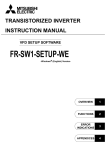
Multi-inputs
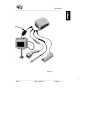
The universal input port of the MIC (sub-D9 pins) recognize
automatically the following devices (see figure 1):
1- Undecoded Laser
2- Pen (Light pen, optical badge reader)
3- RS232C Equipment ( laser projection scanner, in counter
scanner, electronic scale, PDT, ...)
4- Magnetic Stripe Reader
Multi-interfaces
The MIC integrate the following popular interfaces:
1- Keyboard - wedge communication
2- RS232C (using the RS232 cable)
3- TTL Serial ASCII
4- TTL Wand Emulation
5- OCIA
Multi-programming mode
The MIC can be programmed in 3 ways:
1) Through the keyboard of a Windows™ PC
2) Downloading a configuration using a PC Windows™ program
3) Bar codes menu
_____________________________________________________________
MIC 2
User’s Manual
Page 2 - 2
2
Description
_________________________________________________________
Figure 1
_____________________________________________________________
MIC 2
User’s Manual
Page 2 - 3
3
Description
_________________________________________________________
2) Input port
The connector is a SUB-D 9 pins male.
The pin assignement for each input device must be:
a)
Undecoded laser
1 - Start of scan
2 - Data
3 - Good read led
4 - N/C
5 - Trigger signal
6 - Enable laser
7 - GND
8 - GND
9 - Vcc (DC. 5V.)
b) Pen
2 - TTL Data Signal
7 - GND
8 - GND
9 - Vcc (DC.5V.)
c) RS232 Equipment
1 - RD (Received Data Input)
┌── 2 - GND *
│
3 - TD (Transmitted Data Output)
│
4 - RTS (Request to Send Output)
│
5 - N/C
├── 6 - GND *
├── 7 - GND *
└── 8 - GND *
9 - Vcc (DC.5V.)
* Note: All the GND pins (2, 6, 7 and 8) must be connected together.
_____________________________________________________________
MIC 2
User’s Manual
Page 2 - 4
4
Description
_________________________________________________________
d) Magnetic Stripe Reader
1 - Clock ISO 1 or 3
2 - Card selection
3 - GND
4 - Data ISO 2
5 - Clock ISO 2
6 - Data ISO 1 or 3
7 - GND
8 - GND
9 - Vcc (DC.5V.)
3) Interface port
The following interfaces are integrated:
a)
Keyboard - wedge emulation (using an Y-xx cable)
The MIC must be connected between keyboard and
terminal or PC with an “Y” cable.
Data is transmitted to the terminal in a format that
emulates signals from the terminal’s keyboard.
b)
RS232C (using the single/dual RS232C output cable, ref. M-01)
The pin assignement of the DB25 female connector
single RS232 output cable is:
2- TX Output
3- RX Input
4- RTS Output
5- CTS Input
7- GND
13- Vcc (DC.5v) Output/Input
_____________________________________________________________
MIC 2
User’s Manual
Page 2 - 5
5
Description
_________________________________________________________
c)
TTL Serial ASCII
The RJ45 output port pin assignement is:
4 - RX Input
8 - TX Output
6 - GND
7 - CTS Input
d)
TTL Wand emulation
The RJ45 output port pin assignement is:
5 - Vcc (DC 5v.) Input
6 - Ground
7 - Data Pen Bar Low
8 - Data Pen Bar High
4) Physical characteristics
Lenght:
2,4 x 2 x 0,9 (inches) / 60 x 50 x 22 (mm)
Weight:
1,8 oz (50 g)
Electrical characteristics:
Case:
5v. ± 10%, 30 mA.
ABS.
_____________________________________________________________
MIC 2
User’s Manual
Page 2 - 6
6
Installation
_________________________________________________________
Installation
_____________________________________________________________
MIC 2
User’s Manual
Page 3 - 1
1
Installation
_________________________________________________________
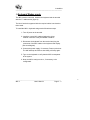
1) Keyboard Wedge mode
The MIC must be connected between the keyboard and the terminal
with the “Y” cables series (figure 2)
The list of terminals supported with the required cables is enclosed to
this manual.
To install the MIC in keyboard wedge mode follow these steps:
1 - Turn off power to the terminal.
2 - Install the correct MIC cables plugging the 8 pins
modular connector to the port labeled "interface".
3 - Disconnect the keyboard from the terminal and plug the
connectors of the MIC cables in the keyboard and display.
(See next diagram)
4 - Connect the power supply, if necessary. Power up the host.
The MIC will beep and after a short delay, will beep again.
5 - Type on the keyboard to verify that the MIC is transparent
to the system.
6 - Now, the MIC is ready to work or, if necessary, to be
configurated.
_____________________________________________________________
MIC 2
User’s Manual
Page 3 - 2
2
Installation
_________________________________________________________
Figure 2
_____________________________________________________________
MIC 2
User’s Manual
Page 3 - 3
3
Installation
_________________________________________________________
2) RS232C Mode
The installation of the MIC requires the M-01 cable and a power supply
(figure 3). See page 2 - 5 for pin assigment.
To install the MIC in RS232C Mode follow these steps:
1 - Turn off power to the terminal
2 - Install the M-01 cable plugging the 8 pins modular
connector to the port labelled “interface”
Plug the jack connector of the power supply.
3 - Power up the terminal and configure RS232C MIC
parameters.
NOTE: To update the configuration, MIC should be
powered off and on.
Figure 3
_____________________________________________________________
MIC 2
User’s Manual
Page 3 - 4
4
Configuration
_________________________________________________________________
Configuration
_________________________________________________________________
MIC 2
User’s Manual
Page 4 - 1
1
Configuration
_________________________________________________________________
When you install MIC for the first time, all its parameters set are in the
default position. If this configuration doesn't correspond with your
application, you must configurate it.
There are three main ways to configure a MIC unit:
I) Via an IBM PC-AT KEYBOARD, with the standard Windows™
based program “NOTEPAD”.
This way, once the MIC is in this mode, it will provide the
options on your screen via menus and you will select the
desired one.
No specal software or hardware is required, just connect MIC in
wedge mode.
II) Via the RS232 port of a IBM PC-AT, with the special Windows™
based program MICCFG.
This user friendly software allows to updownload configurations to
a large amount of MICs in a short time.
No reader is required, just this software and a RS232 cable
(ref. M-05)
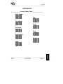
III) Via a BARCODE menu. The user must read bar codes to configure
the MIC. A bar code reader is required with one of the following
interfaces: Laser, RS232 or Light pen emulation.
Once adjusted, the new parameters are saved in an Eeprom (non
volatile memory) which keeps the parameters values even if power-off.
_________________________________________________________________
MIC 2
User’s Manual
Page 4 - 2
2
Configuration
_________________________________________________________________
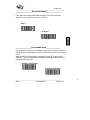
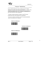
I) PC KEYBOARD QUICK CONFIGURATION
You can program your MIC using your PC-AT keyboard, with this
method the configuration is much easier and eliminates the need of
scanning a list of bar codes.
First connect an undecoded laser or a light pen with MIC and
install it in an IBM Compatible PC AT, then run "Note Pad", a
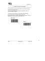
Windows™ environment program, and finally read the bar code
"Enter Keyboard Configuration", now you will begin the
keyboard configuration.
It can be also possible to begin the keyboard configuration by pressing
CRTL for a few seconds and without releasing it, pressing ALT + SPACE.
No reader must be connected to the input port.
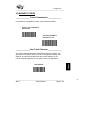
____________Enter keyboard configuration_________
Once you have read this "Enter Keyboard Configuration" bar code, you'll
see the next menu in your PC monitor.
_________________________________________________________________
MIC 2
User’s Manual
Page 4 - 3
3
Configuration
_________________________________________________________________
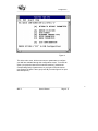
Figure 4
This is the main menu, all the most common parameters to configure
your MIC are available through this configuration screen. To choose an
option, just press the letter that is between brachets [ ] besides the
corresponding family of parameters, so you'll get to new sub-menus
(see example in figure 5 when you press ‘B’), see also figure 6 for input
data description).
_________________________________________________________________
MIC 2
User’s Manual
Page 4 - 4
4
Configuration
_________________________________________________________________
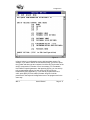
Figure 5
Figure 5 is a tipical configuration screen, the asterisks indicate the selected
parameters and only by pressing a letter you change to a new selection.
Finally, press "ESC" and all the new parameters are saved in the non
volatile memory.
_________________________________________________________________
MIC 2
User’s Manual
Page 4 - 5
5
Configuration
_________________________________________________________________
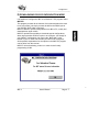
Figure 6
In figure 6 there is a configuration screen with input data request. For
example, if you want to define an intercharacter delay, you have to press
the [J] letter and then type two numbers from 00 to 99 (The duration of the
delay is composed of a number of 5 ms increments). For "Postamble
User Defined" special parameter, after pressing [H] key, you can add up
to 8 programmable suffixes, for each suffix you have to type its
hexadecimal value (Appendix C), if you want to program less than 8
suffix, press [ESC] to finish suffix input data. All types of similar
parameters in the keyboard configuration have to be programmed in the
same way.
_________________________________________________________________
MIC 2
User’s Manual
Page 4 - 6
6
Configuration
_________________________________________________________________
II) DOWNLOADING RS232 CONFIGURATION MODE
It is possible to configure the MIC via a Windows™ PC program called
MICCFG.
This program provides all the features of this manual without the need
to use any reader, just simply connect the MIC to the RS232 port of
your PC (MIC M-05 cable is required).
MICCFG allows to upload configurations from MIC to PC, modify and
download them again to MIC.
MICCFG provides the posibility to download special configurations
when large quantities of MICs require to be configure. Just simply fix
your “Master” configuration and connect the “Blank MIC” to the
RS232 of your PC. After few seconds your MIC will be configured.
All the possible explanations for the options in the MICCFG program
can be taken from this manual.
MICCFG is free distributing, its aim is to make a user friendly
programming of MIC.
_________________________________________________________________
MIC 2
User’s Manual
Page 4 - 7
7
Configuration
_________________________________________________________________
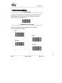
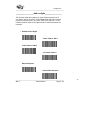
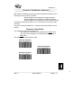
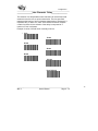
III) BARCODE MENU
1 ) STARTING BARCODE CONFIGURATION
If you want to configurate the MIC using barcode menus, first connect a
reader to MIC and install it in a terminal as described in “Installation”,
then you only have to scan the new desired parameters.
The default parameters are mentioned all along the “Barcode
Configuration” section with a “*” beside the corresponding bar code.
__________Configuration under RS232 device_______
To configurate the MIC with RS232 devices the ENTER/EXIT RS232
configuration barcode should be read before starting configuration.
Once you have changed all the parameters you need to read again this
code in order to keep on working.
When you are in this mode a special “End selection RS232 MODE”
must be used in the numeric keypad appendix D.
ENTER/EXIT RS232
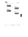
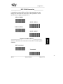
____________AUTO RS232 CONFIGURATION____________
To match the MIC with the RS232 device read the following label
just after the second beep when the MIC is powered.(You have
3 secondes to read this label)
AUTO RS232
_________________________________________________________________
MIC 2
User’s Manual
Page 4 - 8
8
Configuration
_________________________________________________________________
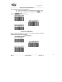
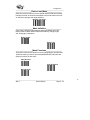
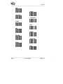
2 ) SYSTEM COMMAND
______________Return to default_____________
This command returns the reader to the original default configuration
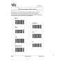
_____________Modify Parameters_____________
This command is used to test new parameters temporarily without
storing them in permanent memory. When you power down the MIC, it
returns to the last set of permanent parameters stored in memory.
_________________________________________________________________
MIC 2
User’s Manual
Page 4 - 9
9
Configuration
_________________________________________________________________
___________Update modified parameters___________
This command stores in permanent memory the modifications done
with "Modify Parameters".
______________Recall last configuration___________
This command returns the MIC from modifications to the last
management stored parameters, without necessarily having to power
down the MIC.
______________Display Prom version______________
By scanning this label, the MIC will display the prom version.
_________________________________________________________________
MIC 2
User’s Manual
Page 4 - 10
10
Configuration
_________________________________________________________________
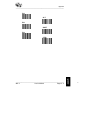
_________________Beeper activation______________
Activate or deactivate the beeper.
* Activated
Not Activated
________________Laser - off mode_____________
If you use "Until Time Out" the laser remains on while the trigger is
pressed, the laser turn off only when you release the trigger or when the
time out elapses. In you use "After Good Read" the laser turn off
after a good read, when you release the trigger or when the time out elapses.
It is also possible to select a CCD device with laser emulation.
* LASER
CCD
* Until Time Out
After Good Read
_________________________________________________________________
MIC 2
User’s Manual
Page 4 - 11
11
Configuration
_________________________________________________________________
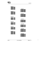
_________________Laser timeout _________________
The time that the laser remains on while trying to read can be
controled. When this time is elapsed the laser will be off until a new
trigger is produced.
When NO TIMEOUT is selected the laser will remain always active.
NOTE: Most of the hand lasers are not designed to work with the laser
always active. Be carefull when using this parameter.
When defining your own laser timeout the step used is 6 seg.
(ie: an input of 8 will generate 6x8=48 seg. timeout).
Max. timeout is: 99x6 = 9 min and 54 seg.
(NO TIMEOUT)
* 6s
12 s
24 s
42 s
102 s
User Defined
_________________________________________________________________
MIC 2
User’s Manual
Page 4 - 12
12
Configuration
_________________________________________________________________
________________No read message_______________
If this option is activated a NO READ message is sent in the selected
keyboard country type when the laser “times out”.
Active
*
No Active
________________Free-hands mode_______________
This option is used with lasers operating in a stand for “free-hands” operation.
Mic will generate a pulsing laser to give the posibility to operate in free-hands
mode.
When enabled is recomeneded to configure the laser-off mode as UNTIL
TIMEOUT. Under configuration stand operation is disabled, that means that
the trigger should be used.
* Pulsing scan Disabled
Pulsing scan Enabled
_________________________________________________________________
MIC 2
User’s Manual
Page 4 - 13
13
Configuration
_________________________________________________________________
3) WEDGE PROGRAMMING
_________________Terminal type__________________
To program a terminal type, scan "terminal type", then scan the two
digit terminal types in the appendix D from configuration list that
corresponds to your terminal or PC.
______________Keyboard country type_____________
Scan the applicable keyboard country type label below that
corresponds with your computer.
* US
UK
German
French
(.../...)
_________________________________________________________________
MIC 2
User’s Manual
Page 4 - 14
14
Configuration
_________________________________________________________________
Italian
Spanish
Norwegian
Belgian
_________________________________________________________________
MIC 2
User’s Manual
Page 4 - 15
15
Configuration
_________________________________________________________________
___________End of message control codes_________
MIC sends a control code after each message, which emulates a
command key of the keyboard, allowing automatic entry data.
You can add any control character by reading "User defined" and then
a code of the "Control code table" in Appendix B.
* Enter
Field Exit
None
CR
Tab
LF
Field Advance
_________________________________________________________________
MIC 2
User’s Manual
Page 4 - 16
16
Configuration
_________________________________________________________________
F1
F2
F3
F4
F5
F6
F7
F8
User Defined
_________________________________________________________________
MIC 2
User’s Manual
Page 4 - 17
17
Configuration
_________________________________________________________________
______________Caps Lock activation______________
In order to transmit alphabetical characters in correct case, MIC must
be set for the caps lock position of the terminal keyboard to which it is
interfaced. (MIC will not check this option if Auto Caps Lock detection
is active)
* NOT Active
Active
___________Auto Caps Lock Detection_____________
When it is impossible to determine the position of the Caps, MIC is able
to detect its position automatically if this option is set. (Only available
with AT and PS2 compatible).
* NOT Active
Active
_________________________________________________________________
MIC 2
User’s Manual
Page 4 - 18
18
Configuration
_________________________________________________________________
________________Alt Mode activation______________
When this mode is actived, the characters are sent to the keyboard
like decimal codes.
For example: “A” letter is sent like ALT + 65.
* NOT Active
Active
__________Numeric keypad activation__________
When this mode is actived, the numeric characters are sent via the
numeric keyboard.
* NOT Active
Active
NOTE: The numeric keyboard should be active.
_________________________________________________________________
MIC 2
User’s Manual
Page 4 - 19
19
Configuration
_________________________________________________________________
____________Control character activation___________
"Control Character Activation" allows MIC to send characters below
20H with the following format:
If it is active, the character is sent to the keyboard like CTRL + X,
X is "A" for 00H, "B" for 01H, ...
If "Control Character Activation" is not active, MIC will send the
received character to the keyboard like a control code.
For example, if 00H is received, it will emulate a "rigth arrow", 01H will
emulate a "left arrow", and so on. See appendix A.
* NOT Active
Active
_________________________________________________________________
MIC 2
User’s Manual
Page 4 - 20
20
Configuration
_________________________________________________________________
4) RS 232 OUTPUT
When this option is chosen, the decoded data is transmitted via
RS232. A special cable M-01 is required.
The RS232 parameters for the output interface are the same as for the
input interface.
_________________________________________________________________
MIC 2
User’s Manual
Page 4 - 21
21
Configuration
_________________________________________________________________
5) WAND EMULATION
______________Same as read barcode____________
When this option is chosen, the decoded data is transmitted like the
read barcode.
_____________Different as read barcode____________
When this option is chosen, the decoded data is transmitted like Code 39.
_____________High speed transmission___________
*
_____________Low speed transmission___________
_________________________________________________________________
MIC 2
User’s Manual
Page 4 - 22
22
Configuration
_________________________________________________________________
6) BARCODE SELECTION
_______________Barcode activation_______________
Read the bar code(s) corresponding to the code formats to be
activated or deactivated.
Disable all
* Enable CODE39
Disable CODE39
* Enable UPC/EAN
Disable UPC/EAN
(.../...)
_________________________________________________________________
MIC 2
User’s Manual
Page 4 - 23
23
Configuration
_________________________________________________________________
Enable CODABAR
* Disable CODABAR
* Enable CODE128
Disable CODE128
Enable 2/5 Interleaved
* Disable 2/5 Interleaved
Enable 2/5 Standard
* Disable 2/5 Standard
(.../...)
_________________________________________________________________
MIC 2
User’s Manual
Page 4 - 24
24
Configuration
_________________________________________________________________
Enable 2/5 Matrix
* Disable 2/5 Matrix
Enable AMES
* Disable AMES
Enable CODE93
* Disable CODE93
(.../...)
_________________________________________________________________
MIC 2
User’s Manual
Page 4 - 25
25
Configuration
_________________________________________________________________
Enable Code MSI
* Disable Code MSI
Enable PLESSEY
* Disable PLESSEY
Enable TELEPEN
* Disable TELEPEN
Enable CODE 11
* Disable CODE 11
_________________________________________________________________
MIC 2
User’s Manual
Page 4 - 26
26
Configuration
_________________________________________________________________
___________Barcode identifiers activation__________
A barcode identifier is a character which can be transmitted as a
preamble before any bar code or as a postambles after any barcode.
The characters are:
CODES
ID
CODES
ID
CODES
ID
Code 39
EAN 13
UPC E
UPC A add 2
EAN 8 add 5
Code TELEPEN
Code 11
2/5 Std (4 bars)
2/5 Matrix
M
F
E
A
J
B
H
R
n
2/5 I
UPC A
EAN 13 add 2
UPC A add 5
UPC E add 2
CODABAR
Code MSI
2/5 Std (6 bars)
I
A
F
A
E
N
M
H
Code 128
EAN 8
EAN 13 add 5
EAN 8 add 2
UPC E add 5
Code 93
Code PLESSEY
AMES
C
F
F
F
E
G
P
m
If you choose AIM ID, the scanner transmits AIM symbology identifiers.
In each barcode section, you can define your own ID character.
Enable Barcode ID
* Disable Barcode ID
_________________________________________________________________
MIC 2
User’s Manual
Page 4 - 27
27
Configuration
_________________________________________________________________
ID TRANSMISSION
* Transmitted before barcode
Transmitted after barcode
* AIM ID NOT Active
AIM ID Active
MINIMUM LENGTH
This option avoid to read barcodes with a length less than the user
defined.
NOTE: When no minimum length checking is desired it should be
fixed to 00.
Minimum length
_________________________________________________________________
MIC 2
User’s Manual
Page 4 - 28
28
Configuration
_________________________________________________________________
7) CODE 39 PARAMETERS
__________________Code selection________________
Activate or deactivate the reading of Code 39.
* Enable CODE39
Disable CODE39
_______________Standard / Full ASCII______________
The full ASCII Code 39 permits the transmission of the 128 characters
of the ASCII table. Every ASCII character is the result of 2 code 39
characters. For example, the characters /D represents a $.
* Standard
Full ASCII
_________________________________________________________________
MIC 2
User’s Manual
Page 4 - 29
29
Configuration
_________________________________________________________________
_____________Start / Stop transmission____________
This function activates the transmission of the start and stop
characters with the data message.
* Start/Stop NOT Transmitted
Start/Stop Transmitted
______________Check digit parameters_____________
In case of high level security required, a check digit can be integrated
at the last position of a code and checked before the transmission.
You can use Modulo 43, CIP (used in the French Pharmaceutical
industry), or Italian (used in the Italian Pharmaceutical industry).
* Not Calculated
Mod 43
CIP
Italian
_________________________________________________________________
MIC 2
User’s Manual
Page 4 - 30
30
Configuration
_________________________________________________________________
_____________Check digit transmission____________
Activate the transmission of the check digit.
NOT transmitted
* Transmitted
________________Barcode identifier_______________
You can activate the default barcode identifier or define one.
* Default
User Defined
_________________________________________________________________
MIC 2
User’s Manual
Page 4 - 31
31
Configuration
_________________________________________________________________
8) INTERLEAVED 2 OF 5 PARAMETERS
__________________Code selection________________
Activate or deactivate the reading of Interleaved 2 of 5.
Enable I 2 of 5
* Disable I 2 of 5
______________Check digit parameters_____________
The Interleaved 2 of 5 check digit can be used as the last encoded
character of a label; it is specially recommended when using variable
length. You can transmit this character or not.
* Not Calculated
Calculated
Check Digit NOT transmitted
* Check Digit Transmitted
_________________________________________________________________
MIC 2
User’s Manual
Page 4 - 32
32
Configuration
_________________________________________________________________
__________________Code length__________________
In order to minimize the chance of misreads, interleaved 2 of 5 codes
are often restricted to one or a few fixed lengths.
It is possible to fix up to 3 lengths. Scan length 1, 2 or 3 and then using
the numeric keypad in Appendix D compose the length. The decoder
can be configured to read and transmit all lengths, in this case, it is
recommended to activate a check digit.
Length 1
Length 2
Length 3
* Variable
______________Barcode identifier______________
It is possible to activate the default barcode identifier or define
one.
* Default
User Defined
_________________________________________________________________
MIC 2
User’s Manual
Page 4 - 33
33
Configuration
_________________________________________________________________
9) STANDARD 2 OF 5 PARAMETERS
__________________Code selection________________
Activate or deactivate the reading of standard 2 of 5.
Enable STD 2 of 5
* Disable STD 2 of 5
______________Check digit parameters_____________
The standard 2 of 5 check digit can be used as the last encoded
character of a label; it is specially recommended when using variable
length. You can transmit this character or not.
* Not Calculated
Calculated
NOT transmitted
* Transmitted
_________________________________________________________________
MIC 2
User’s Manual
Page 4 - 34
34
Configuration
_________________________________________________________________
_________________Start / Stop type________________
Two types of start/stop are used with 2/5 standard, 4 bars and 6 bars.
MIC can use both.
6 BARS
* 4 BARS
__________________Code length__________________
In order to minimize the chance of misreads, standard 2 of 5 codes
are often restricted to one or a few fixed lengths.
Is is possible to fix up to 3 lengths. Scan length 1, 2 or 3 and then
using the numeric keypad in Appendix D compose the length. The
decoder can be configured to read and transmit all lengths, in this
case, it is recommended to activate a check digit.
Length 1
Length 2
Length 3
* Variable
_________________________________________________________________
MIC 2
User’s Manual
Page 4 - 35
35
Configuration
_________________________________________________________________
________________Barcode identifier_______________
It is possible to activate the default barcode identifier or to define one.
* 6 BARS None
6 BARS User Defined
* 4 BARS None
4 BARS User Defined
_________________________________________________________________
MIC 2
User’s Manual
Page 4 - 36
36
Configuration
_________________________________________________________________
10) MATRIX 2 OF 5 PARAMETERS
__________________Code selection________________
Activate or deactivate the reading of Matrix 2 of 5.
Enable Matrix 2 of 5
* Disable Matrix 2 of 5
______________Check digit parameters_____________
The Matrix 2 of 5 check digit can be used as the last encoded
character of a label; it is specially recommended when using variable
length. You can transmit this character or not.
* Not Calculated
Calculated
NOT transmitted
* Transmitted
_________________________________________________________________
MIC 2
User’s Manual
Page 4 - 37
37
Configuration
_________________________________________________________________
__________________Code length__________________
In order to minimize the chance of misreads, Matrix 2 of 5 codes are
often restricted to one or a few fixed lengths.
Is is possible to fix up to 3 lengths. Scan length 1, 2 or 3 and then
using the numeric keypad in Appendix D compose the length. The
decoder can be configured to read and transmit all lengths, in this
case, it is recommended to activate a check digit.
Length 1
Length 2
Length 3
* Variable
________________Barcode identifier_______________
It is possible to activate the default barcode identifier or to define one.
* Default
User Defined
_________________________________________________________________
MIC 2
User’s Manual
Page 4 - 38
38
Configuration
_________________________________________________________________
11) UPC / EAN PARAMETERS
__________________Code selection________________
Activate or deactivate the reading of the different kinds of UPC/EAN.
* Enable EAN 13
Disable EAN 13
* Enable EAN 8
Disable EAN 8
* Enable UPCA
Disable UPCA
* Enable UPCE
Disable UPCE
_________________________________________________________________
MIC 2
User’s Manual
Page 4 - 39
39
Configuration
_________________________________________________________________
______________Check digit parameters_____________
It is possible to transmit the check digit in all kinds of UPC/EAN or not
transmit it.
EAN 13 CHECK DIGIT
* Transmitted
NOT Transmitted
UPC A CHECK DIGIT
* Transmitted
NOT Transmitted
EAN 8 CHECK DIGIT
* Transmitted
NOT Transmitted
_________________________________________________________________
MIC 2
User’s Manual
Page 4 - 40
40
Configuration
_________________________________________________________________
UPC E CHECK DIGIT
* Transmitted
NOT Transmitted
______________System number UPC A_____________
Activate or deactivate the transmission of the UPC A system number
character.
NOT transmitted
* Transmitted
__________________ I S B N Format_______________
* NOT transmitted
Transmitted
* Add-on 378/379 non active
Add-on 378/379 active
_________________________________________________________________
MIC 2
User’s Manual
Page 4 - 41
41
Configuration
_________________________________________________________________
__________________Add on digits_________________
This function allows the reading of 2 or/and 5 digits supplements. If
you choose "Add on required" all UPC/EAN labels that were scanned
must have a supplement, if you chose "Add on not required" , it's not
necessary that all codes have supplement but it will be transmitted if it
is present.
* Disable Add-on Digits
2 Char. Add-on ONLY
5 Char. Add-on ONLY
2 or 5 Char. Add-on
Add on Required
* Add on NOT Required
_________________________________________________________________
MIC 2
User’s Manual
Page 4 - 42
42
Configuration
_________________________________________________________________
______________UPC / EAN Conversion_____________
It is possible to convert UPC A to EAN 13 by transmitting an extra
leading zero before the bar code, and it is also possible to convert
UPC E to the 12 digits equivalent UPC A.
UPC A = EAN 13
UPC E = UPC A
* UPC A = UPC A
* UPC E = UPC E
_____________System number UPC E____________
Activate or deactivate the transmission of the UPC E number system
character.
NOT transmitted
* Transmitted
_________________________________________________________________
MIC 2
User’s Manual
Page 4 - 43
43
Configuration
_________________________________________________________________
________________Barcode identifier_______________
You can activate the default bar code identifier or define one.
EAN 13 Identifier
* Default
User Defined
EAN 13 ADD 2 Identifier
* Default
User Defined
EAN 13 ADD 5 Identifier
* Default
User Defined
_________________________________________________________________
MIC 2
User’s Manual
Page 4 - 44
44
Configuration
_________________________________________________________________
EAN 8 Identifier
* Default
User Defined
EAN 8 Double Identifier
* Not active
Active
EAN 8 ADD 2 Identifier
* Default
User Defined
EAN 8 ADD 5 Identifier
*
Default
User Defined
_________________________________________________________________
MIC 2
User’s Manual
Page 4 - 45
45
Configuration
_________________________________________________________________
UPC A Identifier
* Default
User Defined
UPC A ADD 2 Identifier
* Default
User Defined
UPC A ADD 5 Identifier
* Default
User Defined
_________________________________________________________________
MIC 2
User’s Manual
Page 4 - 46
46
Configuration
_________________________________________________________________
UPC E Identifier
* Default
User Defined
UPC E ADD 2 Identifier
* Default
User Defined
UPC E ADD 5 Identifier
* Default
User Defined
_________________________________________________________________
MIC 2
User’s Manual
Page 4 - 47
47
Configuration
_________________________________________________________________
12) CODE 128 PARAMETERS
__________________Code selection________________
Activate or deactivate the reading of Code 128.
* Enable Code 128
Disable Code 128
_____________Control code parameters____________
This allows the emulation of control keys such as special function
keys, tab or back space, by reading bar code labels composed of
specially defined dual character combinations.
These control codes can be activated either when in a separate label
(see Appendix B), or when embedded in a label, usually as the last
two characters (see Command Translation Table in Appendix A).
* Control Codes NOT Embedded
* Control Codes NOT Active
_________________________________________________________________
MIC 2
User’s Manual
Page 4 - 48
48
Configuration
_________________________________________________________________
Control Code Embedded
Control Code Active
________________Barcode identifier_______________
You can activate the default bar code identifier or define one.
CODE 128 Identifier
* Default
User Defined
_________________________________________________________________
MIC 2
User’s Manual
Page 4 - 49
49
Configuration
_________________________________________________________________
13) CODABAR PARAMETERS
__________________Code selection________________
Activate or deactivate the reading of Codabar.
Enable Codabar
* Disable Codabar
______________Check digit parameters_____________
Codabar can be used with or without check digit and if this one is
used, it is possible to transmit it or not.
* Not Calculated
Calculated
Check Digit NOT transmitted
* Check Digit Transmitted
_________________________________________________________________
MIC 2
User’s Manual
Page 4 - 50
50
Configuration
_________________________________________________________________
_________________CLSI Activation________________
Libraries in the CLSI System used in the United States, require
insertions of spaces within the 14 character label.
For example, the label "388811128161" is transmitted:
"3 888 1112 8161".
* CLSI NOT Activated
CLSI Activated
_____________Start / Stop transmission____________
The start/stop transmission code can be transmitted or not
transmitted according to this selection.
* ST/SP NOT Transmitted
ST/SP Transmitted
_________________________________________________________________
MIC 2
User’s Manual
Page 4 - 51
51
Configuration
_________________________________________________________________
_________________Concatenation_________________
Allows to read two adjacent barcodes in a single read and transmit
them like one barcode. Only the first Start and the last Stop character
are transmitted.
Enable the posibility to read concatenated barcodes.
* NOT Active
Active
When this option is enabled only concatenated barcodes can be read.
If disabled, both concatenated and single barcodes can be read.
* NOT Requested
Requested
____________Concatenation Start / Stop____________
Certain START/STOP combinations can be selected in order to interpret
two barcodes as concatenated.
Used by the American Blood Commission in which left concatenated
barcode must start by: A, B, C, or D and stop by D character. The right
concatenated barcode must start by: D and stop by: A, B, C, or D.
ABC Active
_________________________________________________________________
MIC 2
User’s Manual
Page 4 - 52
52
Configuration
_________________________________________________________________
The first label stop character must match the second label start character
Same Start / Stop Active
The first label stop character and the second label start character are
not checked.
Start / Stop Not Checked
_________________Barcode identifier______________
It is possible to activate the default bar code identifier or to define one.
CODABAR Identifier
* Default
User Defined
_________________________________________________________________
MIC 2
User’s Manual
Page 4 - 53
53
Configuration
_________________________________________________________________
14) CODE 93 PARAMETERS
__________________Code selection________________
Activate or deactivate the reading of Code 93.
Enable Code 93
* Disable Code 93
________________Barcode identifier_______________
It is possible to activate the default bar code identifier or to define one.
CODE 93 Identifier
* Default
User Defined
_________________________________________________________________
MIC 2
User’s Manual
Page 4 - 54
54
Configuration
_________________________________________________________________
15) CODE MSI PARAMETERS
__________________Code selection________________
Activate or deactivate the reading of Code MSI.
Enable Code MSI
* Disable Code MSI
______________Check digit parameters_____________
Code MSI can be used with or without check digit and if this one is
used, it is possible to transmit it or not.
* Not Calculated
Modulo 10
Double Modulo 10
_________________________________________________________________
MIC 2
User’s Manual
Page 4 - 55
55
Configuration
_________________________________________________________________
_____________Check digit transmission____________
* Check Digit Not Transmitted
Check Digit Transmitted
________________Barcode identifier______________
It is possible to activate the default bar code identifier or to define one.
CODE MSI Identifier
* Default
User Defined
_________________________________________________________________
MIC 2
User’s Manual
Page 4 - 56
56
Configuration
_________________________________________________________________
16) CODE PLESSEY PARAMETERS
__________________Code selection________________
Activate or deactivate the reading of Code PLESSEY.
Enable Code PLESSEY
* Disable Code PLESSEY
________________Barcode identifier______________
It is possible to activate the default bar code identifier or to define one.
CODE PLESSEY Identifier
* Default
User Defined
_________________________________________________________________
MIC 2
User’s Manual
Page 4 - 57
57
Configuration
_________________________________________________________________
17) CODE TELEPEN PARAMETERS
__________________Code selection________________
Activate or deactivate the reading of code TELEPEN.
Enable Code Telepen
* Disable Code Telepen
_____________Numeric Mode Activation____________
You can activate or deactivate the numeric mode of code TELEPEN.
Enable Numeric Mode
* Disable Numeric Mode
________________Barcode identifier______________
It is possible to activate the default bar code identifier or to define one.
* Default
User Defined
_________________________________________________________________
MIC 2
User’s Manual
Page 4 - 58
58
Configuration
_________________________________________________________________
18) CODE 11 PARAMETERS
__________________Code selection________________
Activate or deactivate the reading of Code 11.
Enable Code CODE 11
* Disable Code CODE 11
________________Barcode identifier______________
It is possible to activate the default bar code identifier or to define one.
CODE 11 Identifier
* Default
User Defined
_________________________________________________________________
MIC 2
User’s Manual
Page 4 - 59
59
Configuration
_________________________________________________________________
19) RS-232 PARAMETERS
NOTE: To get these parameters updated the MIC should be
powered off and on after changing them.
See section III point 1 for AUTO RS232 configuration
___________________Baud Rate__________________
A baud rate is a unit that measures the speed with which information
are transfered. The baud rate of the MIC must equal the baud rate of
the RS-232 device. Select the rate that matches the device
requirements.
38400
19200
* 9600
4800
2400
1200
600
300
_________________________________________________________________
MIC 2
User’s Manual
Page 4 - 60
60
Configuration
_________________________________________________________________
____________________Data Bits___________________
RS-232 serial communication requires ASCII data to be transmitted in
either 7 or 8 data bits. Select the option that matches the device
requirement.
* 8 Data Bits
7 Data Bits
_____________________Parity____________________
Parity is an additional bit that makes the number of bits in the ASCII
code odd or even. The MIC's parity must match the RS-232 scanner or
device.
* None
Even
Odd
_________________________________________________________________
MIC 2
User’s Manual
Page 4 - 61
61
Configuration
_________________________________________________________________
___________________Stop bits____________________
RS-232 serial communication requires one or two stop bits at the end
of the data. Select the option that matches the device requirements.
1 Stop bit
* 2 Stop Bits
___________________Terminator__________________
Data from the RS-232 device is buffered until a "Terminator" is
received. When the "Terminator" is received the MIC sends the record
to the host system.
CR
LF
* CR LF
ETX
EOT
User Defined
_________________________________________________________________
MIC 2
User’s Manual
Page 4 - 62
62
Configuration
_________________________________________________________________
___________________XON / XOFF_________________
Activate or deactivate XON / XOFF handshaking. When this option is
enabled, MIC sends a XOFF (ASCII 13H) to the RS-232 device to
interrupt reception of data; to restart the flow, it sends the XON
character (ASCII 11H)
Not Active
* Active
___________________ACK / NAK__________________
Enable or disable ACK/NAK handshaking. When ACK/NAK is enabled,
the RS-232 device will not scan again unless an ACK (ASCII 06 H) is
received from the MIC after the transmission of a bar code. If a NAK
(ASCII 15H) is sent from the MIC to the RS-232 device, this one will
retransmit the bar code.
* Not Active
Active
_________________________________________________________________
MIC 2
User’s Manual
Page 4 - 63
63
Configuration
_________________________________________________________________
_______________RTS / CTS OUTPUT______________
When this option is enabled, RTS / CTS hardware protocol is
activated. MIC will output a request to send (RTS) signal when it is
ready to receive any data.
NOTE: RTS/CTS is always active in the input port.
* Not Active
Active
_______________FRAMMING ERROR______________
When this option is enabled, no framming error is detected.
* Detected
Not detected
_____________DOUBLE RS232 INPUT_____________
This option allows two RS232 inputs to share the MIC RS232 input port.
Notes: - Cable M-06 is required.
- Only hardware handshake is supported
- One of the two RS232 devices must provide 10ms interchar delay.
* Not Active
Active
_________________________________________________________________
MIC 2
User’s Manual
Page 4 - 64
64
Configuration
_________________________________________________________________
20) MAGNETIC STRIPE
______________Tracks Transmission______________
It is possible to configurate the order of the track transmission.
* Track 1 or 3 transmitted,
then track 2
Track 2 transmitted,
then track 1 or 3
______________Inter Track Character______________
The default separator character transmitted by the MIC between the
two tracks is CR (ASCII 0D H) but it can be changed by reading "User
Defined" and then the hexadecimal value of this character in the
numeric keypad (Appendix D). See ASCII Table in the Appendix C.
User defined
_________________________________________________________________
MIC 2
User’s Manual
Page 4 - 65
65
Configuration
_________________________________________________________________
_________________Tracks Request________________
You can authorize the transmission if only one track is decoded or
even if both tracks are decoded.
Both Tracks required
* Only one Track required
_____________Start Stop Transmission_____________
You can transmit start/end sentinels or not .
* ST/SP NOT Transmitted
ST/SP Transmitted
_________________________________________________________________
MIC 2
User’s Manual
Page 4 - 66
66
Configuration
_________________________________________________________________
________________LRC Transmission_______________
LRC is a badge check digit. It is possible to transmit it or not.
* LRC NOT Transmitted
LRC Transmitted
_________________________________________________________________
MIC 2
User’s Manual
Page 4 - 67
67
Configuration
_________________________________________________________________
21) DATA FORMAT
MIC is able to manage the decoded data in many different ways using
special features as Preambles,Postambles,....
The followed secuence is:
1º) Apply EDIT FUNCTIONS
2º) Apply CHARACTER SUBSTITUTION
3º) Add BARCODE/DEVICE IDENTIFIERS
4º) Add PREAMBLES
5º) Add POSTAMBLES
6º) Add END OF MESSAGE CONTROL CODES
This way the data will be like this:
{Preambles} {Identifiers}{ EDITED Data}{Postambles}{End of Message}
The user should notice this to get the desired data.
_________________________________________________________________
MIC 2
User’s Manual
Page 4 - 68
68
Configuration
_________________________________________________________________
__________________Preambles___________________
When this option is chosen, up to 8 programable prefix character can
be added to the scannered data. To specify these characters read
"User Defined" and then the hexadecimal value of each character in
the numeric keypad, finally read "End Selection". If you read 8 prefix is
not necessary read "End Selection". You can see the hexadecimal
value of each character in Appendix C.
* None
User Defined
__________________Postambles__________________
If you choose this option, up to 8 programable suffix character can be
added to the scannerd data. To specify these characters read "User
Defined" and then the hexadecimal value of each character in the
numeric keypad, finally read "End Selection". If you read 8 postfix is
not necessary read "End Selection". You can see ASCII Table in the
Appendix C.
* None
User Defined
_________________________________________________________________
MIC 2
User’s Manual
Page 4 - 69
69
Configuration
_________________________________________________________________
______________Character Substitution_____________
Up to 3 scanned characters can be substitued by users defined
characters. To do this, read "Character Substitution 1" , "2" or "3", then
read the hexadecimal value of the character to be substitued and
finally the hexadecimal value of the character to be transmitted in its
place. Use the ASCII Table in Appendix C.
To delete a character whenever it appears, scan FFH as the
hexadecimal value of the character to be transmitted.
To remove a character substitution, scan FFH as the hexadecimal
value of the character to be substitued.
Character substitution 1
Character substitution 2
Character substitution 3
_________________________________________________________________
MIC 2
User’s Manual
Page 4 - 70
70
Configuration
_________________________________________________________________
_________Character Substitution: Advanced_______
MIC allows the posibility to modify the defined character substitution in the
following way only for PC AT interface:
- Allows substitute one character by another character.
- Allows substitute one character by a defined scancode.
- Allows substitute one character by a defined scancode and
modifies the scancode as follows: Ctrl + scancode, Alt+ scancode, Shift+
scancode.
Once the “Character Substitution i” characters has been defined it can be
posible:
Character Substitution
The substitution engine will consider that:
- The value of the character to be substitued is its ASCII value.
- The value of the character to be transmitted in its place is its
ASCII value.
The following barcodes should be used:
Character/character
when substitution 1
Character/character
when substitution 2
Character/character
when substitution 3
_________________________________________________________________
MIC 2
User’s Manual
Page 4 - 71
71
Configuration
_________________________________________________________________
Scancode Substitution
The substitution engine will consider that:
- The value of the character to be substitued is its ASCII value.
- The value of the character to be transmitted in its place is its
scancode value.
The following barcodes should be used:
Character/Scancode
when substitution 1
Character/Scancode
when substitution 2
Character/Scancode
when substitution 3
Scancode Modifiers
When scancode substitution is selected, the substitution engine will modify
the transmitted scancode as follows:
** NO MODIFIER **
*No modifier applied
when substitution 1
*No modifier applied
when substitution 2
*No modifier applied
when substitution 3
_________________________________________________________________
MIC 2
User’s Manual
Page 4 - 72
72
Configuration
_________________________________________________________________
** CRTL MODIFIER **
CTRL+Scancode
when substitution 1
CTRL+Scancode
when substitution 2
CTRL+Scancode
when substitution 3
** ALT MODIFIER **
ALT+Scancode
when substitution 1
ALT+Scancode
when substitution 2
ALT+Scancode
when substitution 3
** SHIFT MODIFIER **
SHIFT+Scancode
when substitution 1
SHIFT+Scancode
when substitution 2
SHIFT+Scancode
when substitution 3
_________________________________________________________________
MIC 2
User’s Manual
Page 4 - 73
73
Configuration
_________________________________________________________________
______________Inter Character Delay______________
The insertion of a delay between each character can sometimes avoid
eventual errors due to a too quick transmission. The time specified
represents the interim of time in between transmission of characters. It
is possible too, to define one, read "User Defined" and then compose
a value from 00 to 99, the duration of the delay is composed of a
number of 5 ms. increments.
Example: A value of 05 will result in a delay of 25 ms.
* 0 ms
10 ms
20 ms
40 ms
80 ms
100 ms
User Defined
_________________________________________________________________
MIC 2
User’s Manual
Page 4 - 74
74
Configuration
_________________________________________________________________
_______________EDITING FUNCTIONS_____________
Editing functions allows manipulate the data before to be transmitted
by using basic functions.
MIC allows to edit up to five different data at the same time which are
defined by its length and type (Masks).
Before fixing any mask parameter it is required that the user fixes the
desired mask.
________________Remove all Masks_______________
Remove all editing functions associated to all masks.
________________ Mask Selection_______________
Always fix the desired mask before start fixing the mask definition and the
functions associated to it.
Mask 1
Mask 2
Mask 3
Mask 4
Mask 5
_________________________________________________________________
MIC 2
User’s Manual
Page 4 - 75
75
Configuration
_________________________________________________________________
________________Remove one Mask_______________
Select the mask you want to remove (MASK SELECTION) and read the
following barcode. All functions associated to this mask will be removed
as well as its data type and length definition.
Remove one mask
_________________Mask definition________________
Each mask is defined by its length and data type.Allways select the
desired mask in MASK SELECTION before defining “String lenght”
and “String type” parameters.
String lenght
String Type
_________________Mask Functions________________
These basic functions will allow the user to manipulate the decoded data.
Select the mask you want to work with (MASK SELECTION) and start
defining functions for that mask.
Copy & Insert
Copy & Replace
Move & Insert
_________________________________________________________________
MIC 2
User’s Manual
Page 4 - 76
76
Configuration
_________________________________________________________________
Move & Replace
Delete Character
Insert Character
Insert DELAY Char.
Delete a Block
Swap Character
__________Delay of the “Delay Character”__________
This parameter defines the “Delay character” duration used by the Edit
function “Insert Delay Char.”. Using appendix D compose a value from
00 to 99. The duration of the delay is composed of a number of 5 ms.
increments. Example: A value of 05 will result in a delay of 25 ms. in
the position in which the “Delay char” is inserted.
'DELAY CHARACTER' DELAY User Defined
_________________________________________________________________
MIC 2
User’s Manual
Page 4 - 77
77
Configuration
_________________________________________________________________
Editing functions is a group of basic functions:
MASK DEFINTION FUNCTIONS:
Input String length:
Fixes the length of the data.Barcodes with different
length that the defined will be transmitted normally.
When fixed a length the positions assigned to data
are: 123,... up to length.
When ‘String Length’ is defined the ‘String Type’ is fixed to
EDIT ALL TYPES. See ‘String Type’ for more information.
Scan two digits in the appendix D.
Input String Type:
It is possible to apply the editing functions to a
defined barcode type, RS232 or Badge device.
‘String Length’ must be defined prior to ‘String
Type’ otherwise an error will result.
To fix the ‘String Type’ scan two digits from appendix D
using the table MASK-1:
_________________________________________________________________
MIC 2
User’s Manual
Page 4 - 78
78
Configuration
_________________________________________________________________
EDIT ALL TYPES
00
CODE 39
41
TELEPEN
42
CODE 128
43
ALL EAN
45
ALL UPC
45
CODABAR
46
CODE 93
47
CODE 11
48
2/5I
49
MSI
4D
PLESSEY
50
STANDARD 2/5 4BARS
52
STANDARD 2/5 6BARS
53
AMES
58
MATRIX 2/5
58
RS232 DEVICE
5A
BADGE
5A
Table MASK-1
When EDIT ALL TYPES is selected no barcode type or device criteria
is checked.
Copy and Insert: This function copies a character and inserts it in
other place of the data.
Two lectures must be done:
- Position Origin: Scan two digits in the appendix D.
- Position Destination: Scan two digits in the appendix D.
For example, if the original label is 12AB3456 and we
want to transmit the data 12AB34B56 then the origin
should be 04 and the destination should be 07.Note
that the new data has got one character more and the
positions of the data are reassigned.
_________________________________________________________________
MIC 2
User’s Manual
Page 4 - 79
79
Configuration
_________________________________________________________________
Move and Insert: This function moves a character and inserts it in
other place of the data.Two lectures must be done:
- Position Origin: Scan two digits in the appendix D.
- Position Destination: Scan two digits in the appendix D.
For example, if the original label is 12AB3456 and we
want to transmit the data 12A34B56 then the origin
should be 04 and the destination should be 07.Note
that the new data has got the same number of
characters and the positions of the data are reassigned.
Copy and Replace: This function copies a character and replaces it in
other place of the data.Two lectures must be done:
- Position Origin: Scan two digits in the appendix D.
- Position Destination: Scan two digits in the appendix D.
For example, if the original label is 12AB3456 and we
want to transmit the data 12AB34B6 then the origin
should be 04 and the destination should be 07.Note
that the new data has got the same number of
characters and the positions of the data are reassigned.
Move and Replace: This function moves a character and replaces it
in other place of the data.Two lectures must be done:
- Position Origin: Scan two digits in the appendix D.
- Position Destination: Scan two digits in the appendix D.
For example, if the original label is 12AB3456 and we
want to transmit the data 12A34B6 then the origin
should be 04 and the destination should be 07. Note
that the new data has got one character less and the
positions of the data are reassigned.
_________________________________________________________________
MIC 2
User’s Manual
Page 4 - 80
80
Configuration
_________________________________________________________________
Insert character: This function inserts a character in a specific
position of the data.Two lectures must be done:
- Position Destination: Scan two digits in the appendix D.
- Character to insert: Scan two digits in the appendix D.
See Appendix C
For example, if the original label is 12AB3456 and we
want to insert the letter X (ASC 58) in the 4th position
the origin should be 04 and the character to insert
should be 58. The data will result as 12AX3456.Note
that the new data has got one character more and the
positions of the data are reassigned.
Insert Delay:
This function inserts a transmission delay in a specific
position of the data.One lecture must be done:
- Position Destination: Scan two digits in the appendix D.
For example, if the original label is 12AB3456 and we
want to insert a delay between the 'B' and the '3' the
destination should be 05.This function must be the
last one that is implemeted .
Delete a character: This function removes a character from the data.
One lecture must be done:
- Position of data to delete: Scan two digits in the appendix D.
For example, if the original label is 123456 and we
want to transmit the data 12356 then the position
should be 04.Note that the positions of the data are
reassigned.
Delete a block: This function removes a complete group of characters
from the data.Two lectures must be done:
- Position Origin: Scan two digits in the appendix D.
- Position Destination: Scan two digits in the appendix D.
For example, if the original label is 12AB3456
and we want to transmit the data 123456 then
the origin should be 03 and the destination
should be 04.
Note that the positions of the data are reassigned.
_________________________________________________________________
MIC 2
User’s Manual
Page 4 - 81
81
Configuration
_________________________________________________________________
Swap character: Swaps the positions of two characters.
Two lectures must be done:
- Position first character: Scan two digits in the appendix D.
- Position second character : Scan two digits in the appendix D.
For example, if the original label is 123456 and we want to
transmit the data 153426 then the position for first character
should be 02 and for the second should be 05. Note that the
new data has got the same number of character and the
positions of the data are reassigned.
_________________________________________________________________
MIC 2
User’s Manual
Page 4 - 82
82
Appendix
_________________________________________________________________
Appendix
_________________________________________________________________
MIC 2
User’s Manual
Page A - 1
1
Appendix
_________________________________________________________________
APPENDIX A
__________Command Translation Table________
Control Codes
Code 128
RIGTH ARROW
LEFT ARROW
UP ARROW
DOWN ARROW
HOME
END
ENTER
SEND
BACKSPACE
TAB
LINE FEED
CLEAR
DEL
RETURN
FIELD +
FIEDL FIELD EXIT
DUP
RESET
BACK TAB
F1
F2
F3
F4
Embedded
1 st
01H
01H
01H
01H
01H
01H
01H
01H
01H
01H
01H
01H
01H
01H
01H
01H
01H
01H
01H
01H
01H
01H
01H
01H
Control Codes
Code 128
2nd
30H
31H
32H
33H
34H
25H
36H
37H
38H
39H
3AH
3BH
3CH
3DH
3EH
3FH
40H
41H
42H
43H
44H
45H
46H
47H
F5
F6
F7
ESC
F8
F9
F10
F11
F12
F13
F14
F15
F16
F17
F18
F19
F20
F21
F22
F23
F24
ALT
SHIFT
CTRL
Embedded
1 st
01H
01H
01H
01H
01H
01H
01H
01H
01H
01H
01H
01H
01H
01H
01H
01H
01H
01H
01H
01H
01H
01H
01H
01H
2nd
48H
49H
4AH
4BH
4CH
4DH
4EH
4FH
50H
51H
52H
53H
54H
55H
56H
57H
58H
59H
5AH
5BH
5CH
5DH
5EH
5FH
_________________________________________________________________
MIC 2
User’s Manual
Page A - 2
2
Appendix
_________________________________________________________________
APPENDIX B
_____________Control Codes Table_______________
RIGHT ARROW
END
LEFT ARROW
ENTER
UP ARROW
SEND
DOWN ARROW
BACKSPACE
HOME
_________________________________________________________________
MIC 2
User’s Manual
Page B - 1
1
Appendix
_________________________________________________________________
TAB
FIELD LINE FEED
FIELD EXIT
CLEAR
DUP
DEL
RESET
RETURN
BACK TAB
FIELD +
ESC
_________________________________________________________________
MIC 2
User’s Manual
Page B - 2
2
Appendix
_________________________________________________________________
F1
F6
F2
F7
F3
F8
F4
F9
F5
F10
_________________________________________________________________
MIC 2
User’s Manual
Page B - 3
3
Appendix
_________________________________________________________________
F11
F17
F12
F18
F13
F19
F14
F20
F15
F21
F16
_________________________________________________________________
MIC 2
User’s Manual
Page B - 4
4
Appendix
_________________________________________________________________
F22
ALT
F23
SHIFT
F24
CTRL
_________________________________________________________________
MIC 2
User’s Manual
Page B - 5
5
Appendix
_________________________________________________________________
ALT+F1
ALT+F7
ALT+F2
ALT+F8
ALT+F3
ALT+F9
ALT+F4
ALT+F10
ALT+F5
ALT+F11
ALT+F6
ALT+F12
_________________________________________________________________
MIC 2
User’s Manual
Page B - 6
6
Appendix
_________________________________________________________________
SHIFT+F1
SHIFT
SHIFT
+F7
SHIFT
+F8
SHIFT
+F9
SHIFT
+F10
SHIFT
+F11
+F2
SHIFT+F3
SHIFT
SHIFT
+F4
+F5
SHIFT +F6
SHIFT +F12
_________________________________________________________________
MIC 2
User’s Manual
Page B - 7
7
Appendix
_________________________________________________________________
CTRL+F1
CTRL
CTRL
+F7
CTRL
+F8
CTRL
+F9
CTRL
+F10
CTRL
+F11
+F2
CTRL +F3
CTRL
CTRL
+F4
+F5
CTRL +F6
CTRL +F12
_________________________________________________________________
MIC 2
User’s Manual
Page B - 8
8
Appendix
_________________________________________________________________
APPENDIX C
_____________ASCII Code Table_____________
First Reading
0
1
2
3
4
5
6
7
0
NUL
DLE
SP
0
@
P
`
p
S
e
c
1
SOH
DC1
!
1
A
Q
a
q
2
STX
DC2
“
2
B
R
b
r
3
ETX
DC3
#
3
C
S
c
s
o
n
d
4
EOT
DC4
$
4
D
T
d
t
5
ENQ
NAK
%
5
E
U
e
u
6
ACK
SYN
&
6
F
V
f
v
7
BEL
ETB
‘
7
G
W
g
w
8
BS
CAN
(
8
H
X
h
x
9
HT
EM
)
9
I
Y
i
y
A
LF
SUB
*
:
J
Z
j
z
B
VT
ESC
+
;
K
[
k
{
C
FF
FS
,
<
L
\
l
|
D
CR
GS
-
=
M
]
m
}
E
SO
RS
.
>
N
^
n
˜
F
SI
US
/
?
O
_
o
DEL
R
e
a
d
i
n
g
_________________________________________________________________
MIC 2
User’s Manual
Page C - 1
1
Appendix
_________________________________________________________________
APPENDIX D
_______________Numeric Keypad_________________
0
5
1
6
2
7
3
8
4
9
_________________________________________________________________
MIC 2
User’s Manual
Page D - 1
1
Appendix
_________________________________________________________________
A
D
B
E
C
F
End Selection
End selection
RS232 MODE
_________________________________________________________________
MIC 2
User’s Manual
Page D - 2
2
Appendix
_________________________________________________________________
NOTES:
_________________________________________________________________
MIC 2
User’s Manual
Page D - 3
3
Appendix
_________________________________________________________________
MIC CONNECTION LIST
June 1998
PC or Terminal model
A PLUS 3477
ACER 1120/1133
ACER 1120SX
ACER 530 Am 386 SXLV
ADDX / NORMEREL AT MAX
ADDX / NORMEREL NS 58
ADDX / NORMEREL S TURBO 2
ADDX / NORMEREL OP AT
APPLE MAC CLASSIC
APPLE MAC SE
APPLE MAC SE/30
APPLE MAC CX
APPLE MAC FX
APPLE MAC SX
APPLE MAC II
APPLE MAC LC II
APPLE MAC LC III
APPLE MAC LC 465
APPLE MAC LC 495
APPLE MAC PERFORMA 450
APPLE QUADRA 800/840
APPLE QUADRA AV/900/950
APRICOT XEN I 386
AST 386 SX/20
AST BRAVO 4/33S
AST BRAVO 4/66D
AXEL IRIS PLATINE
BULL HDS1
BULL MICRAL 200/400
BULL MICRAL 40/65/75/600
BULL MICRAL 600
BULL QUESTAR 210
BULL QUESTAR 310
CANON PC A200
CARRY 1
COMMODORE 1935 386-25
COMMODORE 386-25
COMMODORE PC
COMPAQ 286 E / 386 S
COMPAQ 286/386
COMPAQ 36 XT
COMPAQ SLT 286
COMPAQ DESKPRO
Num.
03
01
01
01
01
01
02
01
04
04
04
04
04
04
04
04
04
04
04
04
04
04
01
01
01
01
01
02
01
01
01
17
18
02
01
01
01
02
01
01
02
01
02
Cables
Y-06
Y-01
Y-02
Y-01
Y-02
Y-02
Y-01
Y-01
Y-04
Y-04
Y-04
Y-04
Y-04
Y-04
Y-04
Y-04
Y-04
Y-04
Y-04
Y-04
Y-04
Y-04
Y-01
Y-01
Y-01
Y-01
Y-02
Y-01
Y-02
Y-01
Y-01
Y-11
Y-11
Y-01
Y-01
Y-02
Y-01
Y-01
Y-02
Y-01
Y-01
Y-02
Y-01
Notes
PWSR
PWSR
PWSR
PWSR
PWSR
PWSR
PWSR
PWSR
PWSR
PWSR
PWSR
PWSR
PWSR
PWSR
PWSR
PWSR
_________________________________________________________________
MIC 2
User’s Manual
Page E - 1
1
Appendix
_________________________________________________________________
PC or Terminal model
Num.
Cables
COMPAQ PROLINEA 386-25S/3-25 ZS
COMPAQ 286/386
COMPAQ 286E/386S
COMPAQ 36XT
COMPAQ DESKPRO
COMPAQ DESKPRO 386S/XL450
COMPAQ SLT 286
COUGAR PC/AT/AT3
DATAPOINT 7322/7333/7373
DATAPOINT 7350
DECISION SYSTEMS INTERNATIONAL
DELL 210/316 SX/433 L/486 P-33
DELL 320 N+
DONATEC PC
DSI 3876
DSI 3877
DSI 3781
DSI 3986
EAGLE PC
ELONEX 325 X
EPSON EQUITY 320 SX+
EPSON PC AX2
EPSON PC E
ERGO SYSTEM
ERICSSON PC
FALCO 500
FALCO INFINITY PC
FORCE F476/477M
FORCE TM 1471W
FORUM AT 286
FT 8700
FUJITSU FT8520
GOLDSTAR GS 317
GOUPIL G6
GOUPIL GOLF
GOUPIL G5 386 / G40
HARRIS ADACOM NV471 / NV472
HERMES H220
HEWLETT PACKARD 700/92
01
01
01
02
02
01
01
01
01
53
03
01
01
02
03
03
03
03
02
01
01
01
02
01
02
21
07
03
03
01
47
29
01
01
01
01
03
01
51
Y-02
Y-01
Y-02
Y-01
Y-01
Y-02
Y-02
Y-01
Y-01
Y-21
Y-07
Y-02
Y-01
Y-01
Y-07
Y-07
Y-07
Y-02
Y-01
Y-02
Y-02
Y-01
Y-01
Y-01
Y-01
Y-01
Y-01
Y-07
Y-07
Y-01
Y-09
Y-09
Y-02
Y-02
Y-02
Y-01
Y-01
Y-02
Y-17
HEWLETT PACKARD 700/96
51
Y-17
HP APOLLO 9000 715/33 IBM PC
HP APOLLO 9000 735 IBM PC
HP VECTRA 286/12
HP VECTRA 386/25
HP VECTRA 486VU/486VL/486-33
HP VECTRA VL 5/100 S3
HP VECTRA VL 5/100 S4
01
01
01
01
01
01
01
Y-02
Y-02
Y-02
Y-01
Y-02
Y-02
Y-02
Notes
PWSR
PWSR
PWSR
BOARD 2V01 W-X
1B-1C 1F-1E Q-R
BOARD 2V01 W-X
1B-1C 1F-1E Q-R
_________________________________________________________________
MIC 2
User’s Manual
Page E - 2
2
Appendix
_________________________________________________________________
PC or Terminal model
Num.
Cables
Notes
HP VECTRA VL 5/90 S4
IBM INDUSTRIAL COMPUTER
IBM PC/AT/AT3
IBM PS/2 8540
IBM PS/2 8560
IBM PS1
IBM PS2/30 H21-H31-H41
IBM PS2/40/50/55/60/80
IBM PS2 56
IBM PSVP SERIE 6382/6384
IBM 3151
IBM 3152-010
IBM 3151-020
IBM 3153
IBM 316X
IBM 3179
IBM 3180
IBM 319X
IBM 3270
IBM 3471
IBM 3472
IBM 3476
IBM 3477
IBM 3486
IBM 3487
IBM 3489
IBM 4684 (W CONNECTION)
IBM PC 330
IBM PC ET PC/XT
ICL P415 GE / P420 GE
ICL DRS 3000
ICL DRS M15
ICL DRS M40/M45/M55/M75/M95
ICL DRS M80
IDEA 276/277
IPC 386DX 33C
IPC 5349
ITT XTRA
KENITEC 486 SX-25
KIMTRON KT-70 PC/XT
KONTRON ICU/IR
KONTRON IPLITE 486 DX-33 LP
KONTRON KAT 286
KONTRON INLITE 386SL-25
KONTRON KPR8/KPR10/KPR20
KONTRON MARLIN
LEANORD CHALLENGER 2
LEANORD TOWER 386 SX-16
MACDONNELL DOUGLAS
01
01
01
01
01
01
01
01
14
01
03
03
03
03
03
03
03
03
03
03
03
03
03
03
03
03
01
01
02
01
01
01
01
01
03
01
01
02
01
02
01
01
01
01
01
01
01
01
50
Y-02
Y-02
Y-01
Y-02
Y-02
Y-02
Y-02
Y-02
Y-02
Y-02
Y-06
Y-06
Y-06
Y-16
Y-07
Y-07
Y-07
Y-07
Y-07
Y-06
Y-06
Y-06
Y-06
Y-06
Y-06
Y-06
Y-02
Y-02
Y-01
Y-02
Y-02
Y-02
Y-02
Y-01
Y-03
Y-01
Y-01
Y-01
Y-02
Y-01
Y-01
Y-02
Y-01
Y-02
Y-01
Y-02
Y-01
Y-01
Y-20
PWSR R5=1K Ohm
_________________________________________________________________
MIC 2
User’s Manual
Page E - 3
3
Appendix
_________________________________________________________________
PC or Terminal model
Num.
Cables
MAI DT 4315
MANNESMANN 9008
MANNESMANN KIENZLE 9008
MANNESMANN KIENZLE PC 920
MEMOREX PC 7000
MEMOREX TELEX 1471
MEMOREX TELEX 1472
MEMOREX TELEX 1191
MEMOREX TELEX 1192
MEMOREX TELEX 1197
MEMOREX TELEX 1488
MEMOREX TELEX 1477
MITAC 3060 G
NCR 3301
NCR 6/8
NCR 7901 / 7912
NCR PC 4I / 6I
NIXDORF M35
NIXDORF M55
NOKIA DATA DT 215 / 326 / 336
NOKIA VDU 191B
NOKIA VDU 471W
NORMEREL AT MAX
NORMEREL OP AT
NORMEREL S TURBO 2
OCIA DTS
OCIA NCR
OLIVETTI CP 486
OLIVETTI M200
OLIVETTI M290S
OLIVETTI M300
OLIVETTI M460
OLIVETTI PC PRO 386SX / 486SX
OLIVETTI PCS 286
PC AT
PC XT
PC 1512
PC 1640
PHILIPS P3102
PHILIPS P3105
PHILIPS P3230/P3204/P3238
PHILIPS P33XX
PHILIPS PC
PLANAR ELT 320-P1 IBM PC
QUME QVT 61
QUME QVT-PCT
REXON SUBMIT 1000
SANYO PC 16
SANYO PC 17
01
22
22
01
02
09
09
09
09
09
09
09
01
01
01
48
02
02
01
01
52
01
01
01
02
20
19
01
02
01
01
01
01
01
01
02
06
06
02
02
01
01
02
01
10
10
01
02
01
Y-02
Y-01
Y-01
Y-01
Y-01
Y-01
Y-01
Y-01
Y-01
Y-01
Y-01
Y-01
Y-02
Y-02
Y-01
Y-18
Y-01
Y-01
Y-01
Y-01
Y-01
Y-01
Y-02
Y-01
Y-01
YYY-02
Y-01
Y-02
Y-02
Y-02
Y-02
Y-02
Y-PC
Y-PC
Y-05
Y-05
Y-01
Y-01
Y-01
Y-01
Y-01
Y-01
Y-08
Y-08
Y-01
Y-01
Y-01
Notes
PWSR
PWSR
PWSR
_________________________________________________________________
MIC 2
User’s Manual
Page E - 4
4
Appendix
_________________________________________________________________
PC or Terminal model
Num.
Cables
SHARP 7100 PC
SHARP 7200 PC
SIEMENS-NIXDORF PCD-H
SIEMENS-NIXDORF 97801
SIEMENS-NIXDORF 97808
SIEMENS-NIXDORF M35
SIEMENS-NIXDORF M55
SIEMENS-NIXDORF OLD SM 9412
SIEMENS-NIXDORF NEW SM 9412
SILICONGRAPHICS INDIGO 2
SPERRY UNIVAC PC
SUN 350/360
SUN 370/380
SUN 410/420
SUN SPAC 5/10/15
SUNRIVER ST SERIES
TANDON PCA 12 SL
TANDON PCA 20
TANDON PCA 30
TANDON PCX 10
TANDON PCX 20
TANDON PLUS TM 7630
TANDY 1000 SL/2
TANDY 3000
TELEVIDEO AT
TELEVIDEO PC
THOMSON MICROMEGA 16
TULIP AT COMPACT 2/3
UNISYS PCI 32/561
UNISYS PWT 120/1120
02
01
01
05
05
02
01
10
01
01
02
45
45
45
45
01
01
01
01
02
01
01
02
01
01
02
02
01
01
54
Y-13
Y-13
Y-02
Y-01
Y-01
Y-01
Y-01
Y-08
Y-08
Y-02
Y-01
Y-14
Y-15
Y-15
Y-15
Y-01
Y-01
Y-01
Y-01
Y-01
Y-01
Y-01
Y-01
Y-01
Y-12
Y-12
Y-01
Y-01
Y-02
Y-22
UNISYS SVT 1120
54
Y-22
UNISYS TO 275
UNISYS TO 300
UNISYS UT 325
VERSAL 6477
VICTOR V286 M/S/C/A/VPC III
VICTOR V286 P
VICTOR V386 A/S/CX/MX/SX
VICTOR VPC IIc VICKI
VISA MC2
VT 220/320/420
VT 510 KBD PC
VT 510 KBD VT
WANG PC - 280
WYSE 160 ASCII
WYSE 160 AT 85
WYSE 160 PC 102 KEYS
47
47
47
02
01
01
01
02
46
11
13
12
01
42
43
41
Y-09
Y-09
Y-09
Y-01
Y-01
Y-02
Y-01
Y-01
Y-09
M-09
Y-02
Y-02
Y-01
Y-09
Y-09
Y-09
Notes
PWSR
R1=R2=220 OHM IN
CABLE
R1=R2=220 OHM IN
CABLE
PWSR
PWSR
PWSR
PWSR
PWSR
PWSR
PWSR
PWSR
_________________________________________________________________
MIC 2
User’s Manual
Page E - 5
5
Appendix
_________________________________________________________________
PC or Terminal model
Num.
Cables
Notes
WYSE 185 ES PC 103
WYSE 2012
WYSE 285
WYSE 325
WYSE 370 AT 85
WYSE 370 PC 102 KEYS
WYSE DECISION 386SX-20/486SX-20
WYSE 120 IBM 316X
WYSE 120/60/65 ANSI
WYSE 120/60/65 ASCII
WYSE 120/60/65 AT 84 KEYS
WYSE 120/60/65 PC 102 KEYS
WYSE 85/185
ZENITH 320 SX
ZENITH AT Z 286
ZENITH Z 425 SX
ZENITH Z SELECT 100 XXX
ZENITH Z STATION 420 SN
ZENITH Z STATION 500
44
01
40
29
39
38
01
28
27
25
26
24
29
01
01
01
01
01
01
Y-09
Y-01
Y-09
Y-09
Y-09
Y-09
Y-01
Y-09
Y-09
Y-09
Y-09
Y-09
Y-09
Y-01
Y-01
Y-01
Y-02
Y-02
Y-02
PWSR
PWSR
PWSR
PWSR
PWSR
PWSR
PWSR
PWSR
PWSR
PWSR
PWSR
PWSR
NOTES:
PWSR : Power supply required
_________________________________________________________________
MIC 2
User’s Manual
Page E - 6
6
Appendix
_________________________________________________________________
SAMPLES SHEET
EAN 13
UPCA
EAN8
UPCE
CODE 39
CODE 128
INTERLEAVED 2/5 (*)
CODABAR (*)
(*) These barcodes are disabled by default.
_________________________________________________________________
MIC 2
User’s Manual
1
Appendix
_________________________________________________________________
_________________________________________________________________
MIC 2
User’s Manual
2
_________________________________________________________________
PROJECTION SCANNERS SHEET
Use this sheet if you are using a projection scanner when programming
the MIC. This way you will avoid barcode misreadings which will cause a
wrong MIC configuration.
Cut through the shadow line to get an open window.
Locate the generated window on the selected MIC configuration barcode.
Show it to the scanner and read.
_________________________________________________________________
MIC 2
User’s Manual
1
_________________________________________________________________
_________________________________________________________________
MIC 2
User’s Manual
2