1
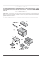
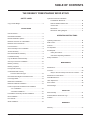
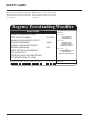
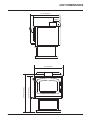
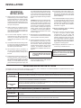
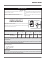
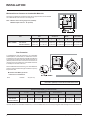
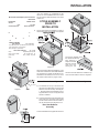
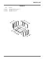
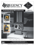
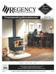
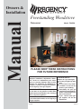
Owners &
Installation
Manual
Freestanding Woodstove
Vancouver
Model: F2402M
PLEASE KEEP THESE INSTRUCTIONS
FOR FUTURE REFERENCE
WARNING:
Improper installation, adjustment, alteration, service or maintenance can cause
injury or property damage. Refer to this
manual. For assistance or additional information consult an authorised installer,
service agency or the gas supplier.
FOR YOUR SAFETY
Do not store or use gasoline or other flammable vapours and liquids in the vicinity of
this or any other appliance.
Installation and service must be performed
by an authorised installer, service agency or
the gas supplier.
918-348
FOR YOUR SAFETY
What to do if you smell gas:
Do not try to light any appliance
Do not touch any electrical switch: do not use any
phone in your building.
Immediately call your gas
supplier from a neighbour's
phone. Follow the gas supplier's instructions.
If you cannot reach your
gas supplier, call the fire
department.
12/07/11
Thank-you for purchasing a
REGENCY FIREPLACE PRODUCT.
The pride of workmanship that goes into each of our products will give you years of trouble-free enjoyment. Should you
have any questions about your product that are not covered in this manual, please contact the REGENCY DEALER
in your area.
Keep those REGENCY FIRES burning.
SAFETY NOTE: If this woodstove is not properly installed, a house fire may result. For your safety, follow the installation instructions, contact local building, fire officials, or authority having jurisdiction about restrictions and installation
inspection requirements in your area.
The authority having jurisdiction should be consulted before installation to determine the need to obtain a permit.
Modular Parts
2
Regency Freestanding Woodstove
TABLE OF CONTENTS
THE REGENCY FREESTANDING WOOD STOVE
SAFETY LABEL
Optional Accessories Installation
- Pedestal Ash Drawer Kit ............................................16
Copy of Data Badge ..............................................................4
- Bottom Shield Ashdrawer Kit......................................16
- Screen Door ...............................................................16
INSTALLATION
- Blower/Fan .................................................................17
- Blower/Fan Wiring Diagram .......................................17
Unit Dimensions ....................................................................5
Residential Installation...........................................................6
Modular Installation Options ..................................................6
Minimum Clearance to Combustibles ....................................7
Minimum Alcove Clearances ................................................8
Floor Protection .....................................................................8
Stove Assembly Prior to Installation ......................................9
Airmate Assembly ..................................................................9
Rear Heat Deflector Assembly ..............................................9
Pedestal Assembly ................................................................9
Leg and Bottom Shield Assembly ........................................10
OPERATING INSTRUCTIONS
Operating Instructions .........................................................18
Draft Control ........................................................................18
First Fire ..............................................................................18
Fan Operation......................................................................19
Ash Disposal........................................................................19
- Safety Precautions .....................................................19
- Ash Drawer Operating Guidelines ..............................19
Safety Guidelines ................................................................19
Chimney & Connector Installation .......................................10
Masonry Chimney................................................................ 11
Masonry Fireplace ............................................................... 11
Factory Built Chimney ......................................................... 11
Combustible Wall Chimney
Connector Pass-Throughs ...........................................12
Recommended Height for Woodstove Flue.........................13
Flue Height Table.................................................................13
Mobile Home Installation .....................................................14
Methods to Maintain Ventilation...........................................14
Listed Components for Mobile Home Installation
MAINTENANCE
Maintenance ........................................................................20
Creosote ..............................................................................20
- Ways to Prevent & Keep Units Free of Creosote .......20
Maintenance of Gold Doors .................................................20
Glass Maintenance ..............................................................20
Latch Adjustment .................................................................20
Door Gasket ........................................................................20
Wood Storage......................................................................20
- U.S. Installations ........................................................15
- Canadian Installations ................................................15
Flue Baffle & Secondary Air Tube Installation .....................15
Brick Installation ..................................................................16
Door Handle ........................................................................16
PARTS LIST
Main Assembly ...................................................................21
Pedestal, Bottom Shield and Legs ......................................22
Firebrick ...............................................................................23
Glass Installation .................................................................16
WARRANTY
Warranty ..............................................................................27
Regency Freestanding Woodstove
3
SAFETY LABEL
This is a copy of the label that accompanies each
Regency Freestanding Woodstove (F2402M).
We have printed a copy of the contents here
for your review.
NOTE: Regency units are constantly being
improved. Check the label on the unit and if
there is a difference, the label on the unit is the
correct one.
Regency Freestanding Woodfire
Model: F2402M
Distributed by:
TESTED TO AS/NZS 4013:1999
Western Australia:
TEST REPORT NUMBER:
ATL18-04
MAXIMUM AVERAGE HEAT OUTPUT
BURNING HARDWOOD:
9.9kW
OVERALL AVERAGE EFFICIENCY
BURNING HARDWOOD:
63%
Air Group Australia
28 Division St
Welshpool WA 6106
Eastern Australia:
Fireplace Products
Australia Pty. Ltd.
21-23 South Link Blvd.
Dandenong, VIC 3175
Manufactured by:
FPI
Fireplace International Ltd.
6988 Venture St.
Delta, BC Canada V4G 1H4
WHEN TESTED IN ACCORDANCE
WITH AS/NZS 4012
TESTED BY AHHA TESTLAB STIRLING
ST THEBARTON SA 5031 (2004)
Date of Manufacture:
JAN FEB MAR APR MAY JUN JUL AUG SEP OCT NOV DEC
2011
2012
2013
Serial
Number
279
918-626
4
Regency Freestanding Woodstove
UNIT DIMENSIONS
27-3/8” (695mm)
24-7/8” (632mm)
6-5/8”
(168mm)
Regency Freestanding Woodstove
29-1/8" (740mm)
30-3/8" (772mm)
24” (610mm)
5
INSTALLATION
RESIDENTIAL
INSTALLATION
1) Please read this entire manual before you
install and use your new woodstove. Failure
to follow instructions may result in property
damage, bodily injury or even death. Be
aware that local Codes and Regulations may
override some items in this manual. Check
with your local inspector.
2) Select a position for your Regency Stove.
Consult the minimum clearance chart for
your model and set the stove in place. For
close clearance installation use listed double
wall connector systems.
3) To insure vertical alignment, suspend a
plumb bob from the ceiling over the exact
center of your stove flue and mark a spot
on the ceiling to indicate the center of the
chimney.
4) Check that the area above the ceiling is clear
for cutting. Re-confirm the clearance from
the stove to combustibles to insure that they
are within the prescribed limits.
5) This woodstove must be connected to a
UL 103 HT (ULC S629) listed chimney or
a code approved masonry chimney with a
flue liner.
6) Install chimney according to chimney manufacturers instructions. The performance of
your woodstove is governed to a very large
part by the chimney system. Too short a
chimney can cause difficult start-up, dirty
glass, backsmoking when door is open, and
even reduced heat output. Too tall a chimney
may prompt excessive draft which can result
in very short burn times and excessive heat
output. The use of an inexpensive flue pipe
damper may be helpful in reducing excessive
draft.
CAUTION: The chimney should be the same
size as the 6" flue outlet on the stove. The
chimney must be listed as suitable for use
with solid fuels. For other types of chimneys
check with your local building code officials.
Do not confuse a chimney with a type “B”
Venting System used for gas appliances
as suitable for a wood burning appliance.
For Mobile Home installations refer to that
section on page 14.
7) Mark the location of the pedestal base or legs
on the floor, then move the stove aside and
mark the position of the floor protector.
8) The floor protector must be of non-combustible material and must extend 16" in front
of the door opening and 6" to the sides and
rear of the unit. Some areas may require
a larger size floor protector. See your local
inspector. For outside air installation refer
to Mobile Home installation instructions on
page 14.
NOTE: In Canada, floor protection must
extend 18" (450mm) to the front and
8" (200mm) to each side and back
of the stove.
10) In seismically active areas, Regency recommends that your unit is secured to the
floor by using the bolt down holes inside
the pedestal (the same ones used in Mobile
Home installations).
11) For residential installations using 6" (152mm)
"C" Vent (single wall) the chimney connector
must be at least 24 gauge steel. Do not use
galvanized pipe. For Mobile Home installation refer to the Mobile Home installation
instructions on page 14.
12) Do not connect this unit to a chimney
serving another appliance.
13) A chimney connector cannot pass through
an attic or roof space, closet or similar
concealed space, or a floor, ceiling, wall
or partition of combustible construction. In
Canada, if passage through a wall, or partition of combustible construction is desired,
the installation shall conform to CAN/CSAB365, Installation Code for Solid-Fuel-Burning Appliances and Equipment.
14) Your Regency Woodstove is not to be connected to any air distribution duct.
Emissions from burning wood or gas could
contain chemicals known to the State of
California to cause cancer, birth defects
or other reproductive harm.
9) When the floor protection is complete, position the stove with the flue collar centered
under the installed chimney.
MODULAR INSTALLATION OPTIONS
The following items are required when assembling your Regency Stove. F2402M unit - the Rear Heat Deflector is supplied with the stove, but if
you choose not to use it you must use the Airmate instead.
Modular Part
Things to consider when choosing options:
Airmate OR
Rear Heat Deflector
Clearances are different. Generally you can get closer clearances with the airmate than with the rear heat deflector.
Pedestal OR
Legs
Convection heat with Airmate vs. Radiant Heat with Rear Heat Deflector. The airmate pushes heat forward and into
the room, the rear heat deflector deflects the heat upward.
There are no performance differences with either the pedestal or legs. It is primarily a personal preference. Legs can
be either painted steel, painted cast, or gold plated cast.
Leg installation requires the bottom shield.
OPTIONS: These can be installed at time of installation or added later:
Modular Option
Things to consider when choosing options
Blower/Fan
Adding the blower will increase the area heated by the stove, it can move warm air beyond the room where the stove
is installed.
Ash Drawer Kit
Screen Door
6
Adding the Ash Drawer Kit makes cleaning ashes out of the stove easier and cleaner.
A simple add-on option that will allow you to enjoy the sound, warmth and view of an open fire.
Regency Freestanding Woodstove
INSTALLATION
AUSTRALIA ONLY
IMPORTANT
The Regency F2402M has been tested with the flue kits listed
below. A default flue kit as listed in AS/NZS 2918:2001 may also
be used.
Use only the instructions and clearance dimensions on this page for
heaters to be installed in Australia.
The Regency F2402M has been tested by the AHHA Testing Laboratory
and conforms to AS/NZS 2918:200, Report No. ATL19-04.
These are the only flue kits certified for use with this heater for
installation in Australia.
AUSTRALIA ONLY
MINIMUM CLEARANCE TO
COMBUSTIBLE MATERIALS
Please read the section below carefully as clearances depend on whether the airmate or the
rear heat deflector is installed on the stove.
Measurements "From Unit" are from the top plate of the stove to a side wall or to a corner,
and from the rear heat shield to a back wall.
Residential Installation Clearances to Combustible Walls
Unit
From Unit
A
Medium F2402M
with Airmate*
with Rear Deflector*
450mm
450mm
From Corner
B
125mm
150mm
C
150mm
225mm
D
755mm
755mm
From Flue Center-Line
E
290mm
315mm
F
445mm
555mm
*Airmate fitted, and 900mm long half round enamelled mild steel flue shield or half perforated decromesh
flue shield fitted
*Rear firebox shield extension fitted, and full length half perforated decromesh flue surround or 900mm
long half round enamelled mild steel flue shield fitted.
Flue systems tested:
Acorn Special Insulated
FLOMET Super Single
Shamic 1A
Floor Protector:
6mm thick fibre cement sheet with thermal conductivity 0.41 W/m degree K underneath heater extending 300mm
in front and 200 mm from the sides of the firebox opening.
Regency Freestanding Woodstove
7
INSTALLATION
Minimum Alcove Clearance to Combustible Materials
The Regency Freestanding models have been alcove approved and must be installed
with a listed double wall connector to the ceiling level.
Note: Minimum alcove ceiling height - 84" (2134mm)
Maximum depth of alcove - 36" (914mm)
From
Unit
Unit
G
Medium F2402M
From Flue
Center-line
H
with Airmate
15" (381 mm)
with Rear Deflector 15" (381 mm)
I
Min.
Width
J
5.5" (139 mm) 27" (685 mm)
6.5" (165 mm) 27" (685 mm)
Min.Hearth
to Rear Wall
K
12" (304 mm)
13" (330 mm)
L
54" (1371 mm)
54" (1371 mm)
48" (1219 mm)
49" (1244 mm)
Floor Protection
A combustible floor must be protected by non-combustible
material (like tile, concrete board, or certified to UL-1618 or
as defined by local codes) extending beneath the heater and
a minimum of 6" (152mm) from each side and minimum 16"
(406mm) from the front face of the stove and minimum 6"
(152mm) (or the rear clearance to combustibles whichever
is smaller) from the rear of the stove.
When installed with horizontal venting, non-combustible floor
protection must beneath the flue pipe and extend 2" (51mm)
beyond each side.
Minimum Overall Width (X) of Floor
Protector for all installations:
Stove
F2402M
36" (914 mm)
NOTE: In Canada, floor protection must extend 18" (450mm) to the
front and 8" (200mm) to each side and back of the stove.
Minimum Overall Depth (y) of Floor Protector
Unit
Medium F2402M
with Airmate
with Rear Deflector
Residential
"C" Vent
Residentiial
Close Clearance
Mobile Home
Close Clearance
Y
Z
Y
Z
Y
46" (1168 mm)
46" (1168 mm)
6" (152 mm)
6" (152 mm)
45"*(1143 mm)
45"* (1143 mm)
5" (127 mm)
5" (127 mm)
45"*(1143 mm)
45"* (1143 mm)
Z
5" (127 mm)
5" (127 mm)
Alcove
Y
45"*(1143 mm)
45"* (1143 mm)
Z
5" (127 mm)
5" (127 mm)
*The rear clearance to combustibles is less than 6", for corner installations the rear corners may be angled to take advantage of the closer clearances.
8
Regency Freestanding Woodstove
INSTALLATION
Minimum Overall Depth (Y) of Floor Protector
Residential
Mobile Home
Residential
Alcove
Unit
Close Clearance
"C" Vent
Close Clearance
Y
Z
*The rear clearance to combustibles is less
than 6", for corner installations the rear corners
may be angled to take advantage of the closer
clearances.
STOVE ASSEMBLY
PRIOR TO
INSTALLATION
All units require either the pedestal or 4 legs attached to the base. The F2402M stove requires
Y
Z
Y
Z
Y
Z
Medium F2402M
with Airmate
46" (1168 mm)
6" (152 mm) 45"* (1143 mm) 5" (127 mm)
45" (1143 mm) 5" (127 mm)
45"* (1143) 5" (127 mm)
with Rear Deflector
46" (1168
mm)
6" (152 mm) 45" (1143
mm) 5" (127 mm)
45" (1143 mm) 5"
(127 mm)
45" (1143) 5" (127
mm)
Diagram 4
Side Shield
Diagram 1
and must be installed unless
the optional airmate has
been selected. It
stops the heat radiated from the flue
collar from overheating the rear
either the Airmate or Rear Heat Deflector on top
of the stove. Clearances to combustible materials
vary depending on whether the airmate or rear
heat deflector is installed, so be sure to check
the clearance information on pages 7 and 8.
wall. The rear heat deflector is installed on top
of the rear heat shield, as shown in diagram 4.
Airmate Assembly
Pedestal Assembly
1) The airmate sits on top of the stove with
the slots in the sides fitting over the curved
deflector on the rear stove top. See diagram
1. Discard the Rear Heat Deflector that is
supplied with the unit, it is not required if the
airmate is installed.
2) Center the airmate and push it forward to the
front of the stove. The back of the airmate
should be level with the back and sides of
the rear heat shield. See diagrams 2 & 3.
Rear Heat Deflector
Assembly
The rear heat deflector is supplied with the stove
Diagram 2
Diagram 3
Regency Freestanding Woodstove
9
INSTALLATION
Leg and Bottom Shield Assembly
The instructions below apply to the steel leg,
painted cast leg and the gold plated cast leg.
It will be easier to attach the legs to the stove
if the stove is tipped on its back (preferably on
a soft surface to prevent scratching). Ensure to
be extremely careful when tipping stove.
1) Remove the 4 bolts from underside of the
base of the pedestal and discard. Also
remove cover plate and put to the side.
2) Line up the heat shield with the bottom of
the unit.
3) Start threading the bolt and washer (supplied
with the bottom shield) for about 1/4 of the
way through the leg with the washers being
underneath the legs. Ensure that the legs
are properly aligned with heat shield and
tighten the bolts.
4) Level the stove by adjusting the levelling
bolts in the bottom of each leg.
1) For easier assembly, tip the stove on its
back (onto a soft surface to prevent scratching).
Hint: If you have chosen the Ash Drawer
option, remove the ash dump cover plates
before attaching the pedestal. See page 16
"Ashdrawer Kit Installation".
2) Remove the blanking plate if
a) you are not installing outside combustion
air or
b) outside air is to be brought in from the
rear of the stove.
3) Unscrew the 4 bolts in the under-side of the
stove. Align the holes in the corners of the
pedestal top with the corresponding holes
in the base of the stove. Fasten using a bolt
and washer for each corner.
support to a minimum height of 3 feet (.9m)
above the roof penetration, or 2 feet (.6m)
above any point within 10 feet (3m) measured horizontally. There must be at least 3
feet (.9m) of chimney above the roof level.
Note: Increasing the chimney height above
this minimum level will sometimes
help your unit to “breathe” better
by allowing a greater draft to be
created. This greater draft can decrease problems such as, difficult
start-ups, back-smoking when door
is open, and dirty glass. It might
be sufficient to initially try with the
minimum required height, and then
if problems do arise add additional
height at a later date.
4) Slide the roof flashing over your chimney
and seal the flashing to the roof with roofing
4) Push the Regency logo into the two holes in
the front bottom left corner of the pedestal
cover plate.
Note: Any paint touch up should be done
prior to placing logo on pedestal.
5) If not using ash drawer, then cover plate must
be installed. If using ash drawer, then disregard
cover plate.
5) Reinstall cover plate.
6) Install logo plate onto heat shield by placing
in 2 holes as shown in diagram.
If you are installing outside combustion air, bend
the tabs out 90 degrees. Pipe fresh air into the
bottom shield by using a minimum 4" duct pipe
with a mesh grill at the outside termination. Attach the pipe to the 2 tabs with screws.
Standard Ceiling Installation
STEP-BY-STEP
CHIMNEY AND
CONNECTOR
INSTALLATION:
Note: These are a generic set of chimney installation instructions. Always follow
the manufacturers own instructions
explicitly. Check Table 1 on page 13
for the Minimum Recommended Flue
Heights.
1) With your location already established, cut
and frame the roof hole. It is recommended
that no ceiling support member be cut for
chimney and support box installation. If it is
necessary to cut them, the members must
be made structurally sound.
2) Install radiant shield and support from above.
3) Stack the insulated pipe onto your finish
10
Horizontal Installation
Regency Freestanding Woodstove
INSTALLATION
MASONRY
CHIMNEY
Ensure that a masonry chimney meets the minimum standards of the National Fire Protection
Association (NFPA) by having it inspected by
a professional. Make sure there are no cracks,
loose mortar or other signs of deterioration and
blockage. Have the chimney cleaned before
the stove is installed and operated. When
connecting the stove through a combustible
wall to a masonry chimney, special methods
are needed.
MASONRY
FIREPLACE
There are listed kits available to connect a stove
to a masonry fireplace. The kit is an adapter
that is installed at the location of the fireplace
damper. The existing damper may have to be
removed to allow installation.
Listed
Liner
FACTORY
BUILT CHIMNEY
When a metal prefabricated chimney is used, the manufacturer's installation instructions must be followed. You must also purchase and install the
ceiling support package or wall pass-through and "T" section package, firestops (where needed), insulation shield, roof flashing, chimney cap, etc.
Maintain proper clearance to the structure as recommended by the manufacturer. The chimney must be the required height above the roof or other
obstructions for safety and proper draft operation.
Regency Freestanding Woodstove
11
INSTALLATION
COMBUSTIBLE WALL CHIMNEY
CONNECTOR PASS-THROUGHS
Minimum chimney clearance to brick
and combustibles 2 in. (50.8mm)
Using a minimum thickness 3.5" (89 mm) brick and a 5/8" (15.9 mm)
minimum wall thickness clay liner, construct a wall pass-through.
The clay liner must conform to ASTM C315 (Standard Specification
for Clay Fire Linings) or its equivalent. Keep a minimum of 12" (304.8
mm) of brick masonry between the clay liner and wall combustibles.
The clay liner shall run from the brick masonry outer surface to the
inner surface of the chimney flue liner but not past the inner surface.
Firmly grout or cement the clay liner in place to the chimney flue liner.
Chimney Flue
Method A: 12" (304.8 mm) Clearance to Combustible Wall
Member:
Minimum
12 in. (304.8mm)
to combustibles
Masonry chimney
Minimum clearance
12 in. (304.8mm)
of brick
Chimney
connector
Fire clay
liner
Method B: 9" (228.6 mm) Clearance to Combustible Wall Member:
Using a 6" (152.4 mm) inside diameter, listed, factory-built Solid-Pak
chimney section with insulation of 1" (25.4 mm) or more, build a wall
pass-through with a minimum 9" (228.6 mm) air space between the
outer wall of the chimney length and wall combustibles. Use sheet
metal supports fastened securely to wall surfaces on all sides, to
maintain the 9" (228.6 mm) air space. When fastening supports to
chimney length, do not penetrate the chimney liner (the inside wall
of the Solid-Pak chimney). The inner end of the Solid-Pak chimney
section shall be flush with the inside of the masonry chimney flue, and
sealed with a non-water soluble refractory cement. Use this cement
to also seal to the brick masonry penetration.
Method C: 6" (152.4 mm) Clearance to Combustible Wall Member:
Starting with a minimum 24 gage (.024" [.61 mm]) 6" (152.4 mm) metal
chimney connector, and a minimum 24 gage ventilated wall thimble
which has two air channels of 1" (25.4 mm) each, construct a wall
pass-through. There shall be a minimum 6" (152.4) mm separation area
containing fiberglass insulation, from the outer surface of the wall thimble
to wall combustibles. Support the wall thimble, and cover its opening
with a 24-gage minimum sheet metal support. Maintain the 6" (152.4
mm) space. There should also be a support sized to fit and hold the
metal chimney connector. See that the supports are fastened securely
to wall surfaces on all sides. Make sure fasteners used to secure the
metal chimney connector do not penetrate chimney flue liner.
Method D: 2" (50.8 mm) Clearance to Combustible Wall Member:
Start with a solid-pak listed factory built chimney section at least
12" (304 mm) long, with insulation of 1" (25.4 mm) or more, and an
inside diameter of 8" (2 inches [51 mm] larger than the 6" [152.4
mm] chimney connector). Use this as a pass-through for a minimum
24-gage single wall steel chimney connector. Keep solid-pak section
concentric with and spaced 1" (25.4 mm) off the chimney connector
by way of sheet metal support plates at both ends of chimney section.
Cover opening with and support chimney section on both sides with
24 gage minimum sheet metal supports. See that the supports are
fastened securely to wall surfaces on all sides. Make sure fasteners
used to secure chimney flue liner.
12
Regency Freestanding Woodstove
INSTALLATION
RECOMMENDED HEIGHTS FOR
WOODSTOVE FLUE
Simple rules on draft. See Table 1.
3) Add 4% overall for each 1000' (3.5m) above
sea level.
1) At sea level minimum height is 12' (3.7m)
Example: a)
straight.
1-1/2 ft. of horizontal run
one "T"
2) Add the following vertical height to compenTotal Addition (at sea level)
sate for:
45 deg. elbow = 1 ft. (.3m)
Example: b)
90 deg. elbow = 2 ft. (.6m)
One 90 deg. elbow
"T"
= 3 ft. (.9m)
2 ft. of horizontal run
Each foot of horizontal run = 2 ft. (.6m)
one "T"
Total Addition (at sea level)
= 3 ft. (.9m)
= 3 ft. (.9m)
= 6 ft. (1.8m)
Recommended Flue Height
Elevation
Example a)
Example b)
0' (0m)
18' (5.5m)
21' (6.4m)
1000' (305m)
18.72' (5.7m) 21.84' (6.7m)
2000' (610m)
19.44' (5.9m) 22.68' (6.9m)
5000' (1524m)
21.60' (6.6m) 25.20' (7.7m)
8000' (2438m)
23.76' (7.2m) 27.72' (8.5m)
= 2 ft. (.6m)
= 4 ft. (1.2m)
= 3 ft. (.9m)
= 9 ft. (2.7m)
TABLE 1
MINIMUM RECOMMENDED FLUE HEIGHTS IN FEET
(Measured from the top of the unit)
# OF ELBOWS
ELEVATION (FT)
ABOVE SEA LEVEL
0-1000
1000-2000
2000-3000
3000-4000
4000-5000
5000-6000
6000-7000
7000-8000
8000-9000
9000-10000
0
12.0
12.5
13.0
13.5
14.0
14.5
15.0
15.5
16.0
16.5
2 x 15o 4 x 15o 2 x 30o
13.0
13.5
14.0
14.5
15.0
15.5
16.0
16.5
17.0
17.5
14.0
14.5
15.0
15.5
16.0
17.0
17.5
18.0
18.5
19.0
15.0
15.5
16.0
17.0
17.5
18.0
18.5
19.0
20.0
20.5
4 x 30o 2 x 45o 4 x 45o
18.0
19.0
19.5
20.0
21.0
21.5
22.5
23.0
24.0
24.5
16.0
16.5
17.0
18.0
18.5
19.0
20.0
20.5
21.0
22.0
20.0
21.0
21.5
22.5
23.0
24.0
25.0
25.5
26.5
27.0
NOTE: No more than two offsets (four elbows) allowed. Two 45o elbows equal one 90o elbow.
Regency Freestanding Woodstove
13
INSTALLATION
compound. Secure the flashing to your roof with nails or screws.
5) Place the storm collar over the flashing, sealing the joints with a silicone caulking.
6) Fasten the raincap with spark screens (if
required) to the top of your chimney.
7) For optimum efficiency when installing into
a masonry chimney, size accordingly, i.e.
the 6" (152mm) flue dia. is 28.28 sq.in.
8) To complete your chimney installation, install
the double wall connector pipe from the
stove’s flue collar to the chimney support
device.
9) If you are using a horizontal connector,
the chimney connector should be as high
as possible while still maintaining the 18"
(457mm) minimum distance from the horizontal connector to the ceiling.
10) NOTE: Residential Close Clearance and
Alcove installations require a listed double wall connector from the stove collar
to the ceiling level.
CAUTION: At no time use unlabelled
parts, or substitute parts made for another
chimney system.
Install as per chimney manufacturer's
installation instructions.
WARNING: Operate only with door fully
closed - open feed door to feed fire only.
In addition to standard installation instructions
the following requirements are mandatory for
installation in a mobile home.
1) The stove must be permanently bolted to
the floor of the Mobile Home using the floor
screws provided.
2) The stove must have a permanent outside
air source for combustion.
3) The stove must be electrically grounded to
the steel chassis of the Mobile Home.
4) A listed double-wall connector chimney
system, roof thimble, spark arrestor and roof
flashing kit suitable for use in Mobile Homes
must be used.
5) If the chimney exits the Mobile Home at a
location other than through the roof, and exits at
a point 7ft. (2130mm) or less above the ground
level on which the Mobile Home is positioned
a guard or method of enclosing the chimney
shall be fitted at the point of exit for a height up
to 7ft. (2130mm).
6) The chimney shall be attached directly to
the room heater and shall extend at least 3 ft.
(914mm) above the part of the roof through
which it passes. The top of the chimney should
project at least 2ft. (610mm) above the highest
elevation of any part of the Mobile Home within
10 ft. (3048mm) of the chimney.
7) The chimney system shall comply with Local
Requirements.
8) Any openings in a chimney guard where
required must not permit the entrance of 3/4"
(19mm) diameter rod.
9) CAUTION: THE STRUCTURAL INTEGRITY
OF THE MOBILE HOME ROOF, FLOOR,
WALLS AND CEILING MUST BE MAINTAINED.
10) Check any other local building code as other
local codes may apply.
11) WARNING: DO NOT INSTALL IN A SLEEPING ROOM OF A MOBILE HOME.
12) Use silicone to create an effective vapour
barrier at the location where the chimney or
other component penetrates to the exterior of
the structure.
14
Regency Freestanding Woodstove
INSTALLATION
1 6FAMH
Flashing
Chimney Length
The diagrams below illustrate one way to install 1 6L3
Chimney Length
your unit into a standard ceiling or with a horizontal 1 6L1
Rain Cap
connector. Check with your dealer or installer for 1 CPE
information on other options available to you.
SECURITY S2100
Qty.Part #
Description
1 DL42A-6
Connector Kit
1 6XSF
Support
1 6XFA
Flashing
Chimney Length
Once you have properly marked the position of 1 6XL3
Chimney Length
your unit and the floor protection as outlined in the 1 6XL18
Rain Cap
Residential Installation items #1 through #8, a sup- 1 6XCPE
MOBILE HOME INSTALLATION
ply of fresh air has to be supplied to your unit. Cut
a minimum 4 inch diameter hole through your floor
protector and the floor directly under your pedestal
base to the outside. Use 4" duct pipe with a mesh
grill to pipe fresh air into the pedestal area. Block off
the hole in the back of the pedestal with the square
plate and the two 1/2" (13mm) screws provided.
METAL-FAB TEMP/GUARD 2100
Qty.Part #
Description
1 6DWBK
Connector
1 6TGRS
Roof Support
1 6TGG36
Chimney Length
1 6TGG12
Chimney Length
1 6TGF
Flashing
Rain Cap
Place your unit in position and secure it to the floor 1 6TGC
using two lag bolts 3/8" x 3-1/2" (10mm x 89mm)
through the two holes inside the pedestal base. It AMERI-TEC HS
Description
is important to maintain the structural integrity of Qty.Part #
Connector
the Mobile Home floor, walls and roof when install- 1 6DCC
1 6HSRS-12 Roof Support (6PLRS-12-BK)
ing your unit.
1 6F
Flashing
Chimney Length
For Mobile Home units installed in the U.S. the 1 6HS-36
Chimney Length
unit must be grounded using a #8 ground wire with 1 6HS-18
1 6HS-RCS Rain Cap (6PL-MPC)
approved termination and star washer.
LISTED COMPONENTS
FOR MOBILE HOME
INSTALLATION
Install as per chimney manufacturer's installation instructions.
FLUE BAFFLE &
SECONDARY AIR TUBE
INSTALLATION
The flue baffle system located in the upper area
of the firebox is removable to make cleaning
your chimney system easier. The baffles must
be installed prior to your first fire. Smoke spill-
Side View
age and draft problems may occur if the
baffles are improperly positioned. Check
the position of the baffles on a regular basis as
they can be dislodged if too much fuel is forced
into the firebox.
SIMPSON DURA-PLUS
Qty.Part #
Description
1 6DVL8693 Connector Kit
1 6DP-MH9096 Mobile Home Kit
ICC EXCEL 2100
The Regency F2402M and S2402M Freestanding
Qty.Part #
Description
pedestal units are approved for installation in a
1 6CL48
48" (1219mm)Chimney length
Mobile Home if one of the following pipe systems
Front View
(also in 12" (305mm), 18"
is used.
(457mm), 24" (610mm) lengths.
1 6RC
Rain Cap
Freestanding Stove
U.S. Installation*
1 6RCS
Spark Screen (for rain cap)
1 6RDS/SQS Round/Square support box
METALBESTOS SSII
1 6VF
Flashing
Qty. Part #
Description
1 6UBA
"Ultrablack" Close Clearance The unit arrives with the 2 baffles on the floor
1 6DS-VK
Connector Kit
of the firebox.
Connector
1 6TMH
Shield/Support
1 6TAF-6
Flashing
1) If all 4 air tubes are installed continue on to
Canadian Installations*
1 6T-36
Chimney Length
Step 2), if not, follow the instructions below.
1 6T-18
Chimney Length
Install the air tube into the holes in the side
SECURITY S2100 (see above for details)
1 6T-CT
Rain Cap
channels. The notch goes on the right hand
side with the air holes facing toward the door.
ICC EXCEL 2100 (see above for details)
PRO-JET 3103
Slide the tube into the left hand side, as far
Qty.Part #
Description
as possible and
then
bring it back into the
Front
View
SELKIRK SENTINAL CF
1 PV06-TK
Connector
hole on the right hand side until it locks into
1 CSB
Shield/Support
position. If the tube will not slide in easily,
*The use of alternate pitch flashings, support box
1 RRS
Radiation Shield
simply use a pair of vise grips or pliers and
extensions, additional chimney lengths, and ad1 LFR03
Flashing
tap it into place with a hammer. A tighter
ditional chimney bracing, may be used on each of
1 SL3
Chimney Length
fit will ensure the tube will not move when
the previously listed systems. These parts though
1 SL1
Chimney Length
the unit is burning.
must be from the same system as listed, and must
1 RCSA
Rain Cap
be a similar and/or complimentary part.
SECURITY ASHT
Qty.Part #
Description
1 DL42A-6
Connector Kit
1 6SS
Shield/Support
Regency Freestanding Woodstove
CAUTION: At no time use unlabelled
parts, or substitute parts made for
another chimney system.
2) Slide the left baffle over the air tubes from
the front and then push it to the back.
15
INSTALLATION
BRICK INSTALLATION
Firebrick is included to extend the life of your
stove and radiate heat more evenly. Check to
see that all firebricks are in their correct positions and have not become misaligned during
shipping.
STEP-BY-STEP
OPTIONAL
ACCESSORIES
INSTALLATION
The "AD" brick in the drawings above is the
brick covering the Ash Dump hole that is used
when the Ash Drawer Kit is installed.
The pieces listed below can be purchased and
installed during the initial installation or added
on later.
4) Push the ash plug into the hole inside the
firebox and replace all the bricks except
for the brick over the ash plug. See brick
diagram.
5) Place the ash plug tool beside the lid, then
slide the ash drawer inside.
Pedestal Ash Drawer Kit
1) Remove the bricks from the floor of the
firebox.
2) If using ashdrawer, discard cover plate.
3) Remove the ash dump cover plates (one
inside the firebox and one on the underside
of the firebox) by removing the two nuts and
bolts holding the 2 plates together from inside
the firebox.
4) Push the ash plug into the hole inside the
firebox and replace all the bricks except
for the brick over the ash plug. See brick
diagram.
DOOR HANDLE
Attach spring handle by rotating counter
clockwise onto rod. Ensure that the rod fits
into the entire length of the spring handle. See
Diagram below.
SCREEN DOOR
Hook screen to the inside on the right side
of the firebox door opening. Lock in place by
turning handle.
5) Place the ash drawer lid inside the pedestal,
and the ash plug tool beside the lid, then
slide the ash drawer inside so it sits on top
of the lid.
Hooks
Handle Lock
Back Side of Screen Shown
NOTE: The handle must be positioned at 10
o'clock when closed to avoid the handle from getting hot and to ensure the screen stays in place.
GLASS INSTALLATION
Remove the door from the stove and remove
the glass retainer. Position the glass in the door,
make sure that the glass gasketing will properly seal your unit, and replace the retainer, it
should rest on the gasket not the glass. Tighten
securely, but do not wrench down on the glass
as this may cause the glass to break.
Bottom Shield Ash Drawer Kit
1) Remove the bricks from the floor of the
firebox.
2) Remove and discard the cover plate by
removing the two screws on the front of the
Bottom Shield.
3) Remove the ash dump cover plates (one
inside the firebox and one on the underside
of the firebox) by removing the two nuts and
bolts holding the 2 plates together from inside
the firebox.
16
Handle at 10 o'clock position.
Regency Freestanding Woodstove
INSTALLATION
Blower/Fan
1) Remove the two screws from the top of the
fan housing.
2) Slide the fan up into the rear heat shield.
3) After aligning holes, secure the fan to the rear
heat shield using the two screws removed
earlier.
CAUTION: The connection cord should not
be in contact with any hot surfaces.
Do not route cord under or in front
of unit.
Read the operating instructions for the fan before
using. See Page 19.
eutral
1
A
ive
anual
Auto
Switch
reen
Fan
Switch
lac
igh
lac
White
lac
ow Red
Fan hermodisc
normallyopen
round
lac
Fan
Fan
round
Blower/Fan Wiring Diagram
WARNING: Electrical Grounding Instructions
This appliance is equipped with a three pronged
(grounding) plug for your protection against shock
hazard and should be plugged directly into a properly
grounded three-prong receptacle. Do not cut or remove
the grounding prong from this plug.
Regency Freestanding Woodstove
CAUTION: Label all wires prior to disconnection
when servicing controls. Wiring errors can cause
improper and dangerous operation.
17
OPERATING INSTRUCTIONS
OPERATING
INSTRUCTIONS
With your unit now correctly installed and safety
inspected by your local authority, you are now
ready to start a fire. Before establishing your
first fire, it is important that you fully understand
the operation of your draft control.
WARNING
Fireplace Stoves equipped with doors
should be operated only with doors fully
open or doors fully closed. If doors are
left partly open, gas and flame may be
drawn out of the fireplace stove opening, creating risks from both fire and
smoke.
When operated with doors open the
manufacturer supplied screen must
be used.
DRAFT CONTROL
Both the primary and air wash drafts are controlled by the control rod located on the left side
of the unit (when facing the unit). To increase
your draft - pull open, and to decrease - push
closed. All units have a secondary draft system
that continually allows combustion air to the
induction ports at the top of the firebox, just
below the flue baffle.
Important: If you are using room air for combustion, make sure that the back cover plate at the
rear of the pedestal is not installed. The cover
plate must be installed on the unit if your stove
is located in a mobile home or if using outside
air from the bottom.
Pull - Open
Push - Closed
WARNING: To build a fire in ignorance
or to disregard the information contained in this section can cause serious
permanent damage to the unit and void
your warranty!!
FIRST FIRE
When your installation is completed and inspected you are ready for your first fire.
1) Open control fully.
2) Open firebox door and build a small fire using paper and dry kindling on the firebrick
hearth. Secure door on the firebox and wait
a few minutes for a good updraft in the flue to
establish the fire. (Leaving the door slightly
open will help your fire start more rapidly.)
CAUTION: Never leave unit unattended if door is left open. This
procedure is for fire start-up only,
as unit may overheat if door is left
open for too long.
3) With the draft still in the fully open position
add two or three seasoned logs to your fire.
Form a trench in the ash bed to allow air to
reach the rear of the firebox prior to closing
the door.
4) After about 45 minutes, when your wood
has begun to burn strongly, adjust your draft
control down to keep the fire at a moderate
level.
WARNING: Never build a roaring
fire in a cold stove. Always warm
your stove up slowly!
5) Once a bed of coals has been established
on the firebrick hearth, you may adjust the
draft control to a low setting to operate the
unit at its most efficient mode.
6) During the first few fires, keep the combustion rate at a moderate level and avoid a
large fire. Only after 5 or 6 such fires can
you operate the stove at its maximum
setting, and only after the metal has been
warmed.
7) For the first few days, the stove will give
off an odour from the paint. This is to be
expected as the high temperature paint
becomes seasoned. Windows and/or doors
should be left open to provide adequate
ventilation while this temporary condition
exists. Burning the stove at a very high
temperature the first few times may damage
the paint. Burn fires at a moderate level the
first few days.
8) Do not place anything on the stove top
during the curing process. This may result
in damage to your paint finish.
18
9) During the first few days it may be more
difficult to start the fire. As you dry out your
firebrick and your masonry flue, your draft
will increase.
10) For those units installed at higher elevations
or into sub-standard masonry fireplaces,
drafting problems may occur. Consult an
experienced dealer or mason on methods
of increasing your draft.
11) Some cracking and popping noises may be
experienced during the heating up process.
These noises will be minimal when your unit
reaches temperature.
12) Before opening your door to reload, open
draft fully for approximately 10 to 15 seconds
until fire has been re-established. This will
minimize any smoking.
13) All fuel burning appliances consume oxygen
during operation. It is important that you
supply a source of fresh air to your unit
while burning. A slightly opened window is
sufficient for the purpose. If you also have
a fireplace in your home, a downdraft may
be created by your Regency Stove causing
a draft down your chimney. If this occurs,
slightly open a window near your unit.
CAUTION: If the body of your
unit, flue baffle or any part of the
chimney connector starts to glow,
you are overfiring. Stop loading
fuel immediately and close the
draft control until the glow has
completely subsided.
14) Green or wet wood is not recommended for
your unit. If you must add wet or green fuel,
open the draft control fully until all moisture
has been dispersed by the intense fire.
Once all moisture has been removed, the
draft control may be adjusted to maintain
the fire.
15) If you have been burning your stove on a
low draft, use caution when opening the
door. After opening the damper, open the
door a crack, and allow the fire to adjust
before fully opening the door.
16) The controls of your unit or the air supply
passages should not be altered to increase
firing for any reason.
17) If you burn the unit too slowly or at too low
a setting your unit will not be operating as
efficiently as it can. An easy rule of thumb
says that if your glass is clean, then your
flue is clean and your exhaust is clean.
Burn the stove hot enough to keep your
glass clean and you won't need to clean
your flue as often.
Regency Freestanding Woodstove
OPERATING INSTRUCTIONS
FAN OPERATION
Automatic
To operate the fan automatically, push the
bottom switch on the side of the fan housing
to "AUTO" and the top switch to either "HIGH"
or "LOW" for fan speed.
This will allow the fan to turn on as the stove
has come up to operating temperature. It will
also shut the fan system off after the fire has
gone out and the unit cooled to below a useful
heat output range.
Manual
To manually operate the fan system push the
bottom switch to "MAN" and the top switch
to either "HIGH" or "LOW". This will bypass
the sensing device and allow full control of
the fan.
Switching from "AUTO" to "MAN" or "HIGH" to
"LOW" may be done anytime.
ASH DISPOSAL
During constant use, ashes should be removed
every few days. The Ash Drawer option features
a convenient ash dump for easy removal of ash,
see "Modular Options" on page 6.
Safety Precautions
1) Do not allow ashes to build up to the loading
doors! Only remove ashes when the fire
has died down. Even then, expect to find
a few hot embers.
2) Please take care to prevent the build-up of
ash around the start-up air housing located
inside the stove box, under the loading door
lip.
3) Never start a fire if the ash plug and ash
drawer are not in place. This will cause
overfiring which can cause excessive warping of the stove. Evidence of overfiring can
void the warranty on your stove.
4) The firebricks are brittle and can be damaged
if the plug is replaced carelessly or pieces
that are too large are forced through the
hole.
Ash Drawer Operating Guideline
1) Only clean ashes out of the stove when the
unit has cooled down. Remove the plug by
lifting on the handle using the tool provided.
The plug may still be warm, use caution.
Push the ashes down the hole into the ash
drawer, the large pieces can be left in the
firebox and burned during the next fire or
removed through the door opening.
2) Always leave 1/2 to 1 inch (13mm to 25mm)
of ash in the bottom of the firebox. This helps
in easier starting and a more uniform burn
of your fire. Replace ash plug when ashes
have been removed.
3) Pedestal Units:
To remove the drawer, lift slightly and slide
it out. When the drawer is completely out,
slide the cover plate over the ash drawer
and carry away.
5) Do not overfire heater. If the chimney connector, flue baffle or the stove top begin to
glow, you are overfiring. Stop adding fuel and
close the draft control. Overfiring can cause
extensive damage to your stove including
warpage and premature steel corrosion.
Overfiring will void your warranty.
6) Do not permit creosote or soot build-up in the
chimney system. Check and clean chimney
at regular intervals. Failure to do so can result
in a serious chimney fire.
7) Your Regency stove can be very hot. You
may be seriously burned if you touch the
stove while it is operating, keep children,
clothing and furniture away. Warn children
of the burn hazard.
Bottom Shield (with Legs) Units:
To remove the drawer, lift slightly and slide
it out, and carry it away.
8) The stove consumes air while operating,
provide adequate ventilation with an air
duct or open a window while the stove is in
use.
9) Do not connect this unit to a chimney flue
serving another appliance.
4) When emptying the ash drawer, make sure
the ashes are cold. Ashes should be placed
in a metal container with a tight fitting lid.
The closed container of ashes should be
placed on a non-combustible floor or on the
ground, well away from all combustible materials, pending final disposal. If the ashes
are disposed of by burial in soil or otherwise
locally dispersed, they should be retained in
the closed container until all cinders have
thoroughly cooled. Other waste should not
be placed in the ash container.
5) Before putting the ash drawer back into
place, make sure the ash plug is back in
place.
Pedestal Units: make sure the cover lid is
off.
SAFETY GUIDELINES
AND WARNINGS
1) Never use gasoline, gasoline type lantern
fuels, kerosene, charcoal lighter fuel, or
similar liquids to start or ‘freshen up’ a fire
in your heater. Keep all such liquids well
away from the heater while it is in use.
2) Keep the door closed during operation and
maintain all seals in good condition.
3) Do not burn any quantities of paper, garbage, and never burn flammable fluids such
as gasoline, naptha or engine oil in your
stove.
Regency Freestanding Woodstove
4) If you have smoke detectors, prevent smoke
spillage as this may set off a false alarm.
10) Do not use grates or andirons or other
methods for supporting fuel. Burn directly
on the bricks.
11) Open the draft control fully for 10 to 15
seconds prior to slowly opening the door
when refuelling the fire.
12) Do not connect your unit to any air distribution duct.
13) Your woodstove should burn dry, standard
firewood only. The use of cut lumber, plywood, “mill ends”, etc. is not allowed as this
fuel can easily overheat your woodstove.
Evidence of excessive overheating will void
your warranty. As well, a large portion of
sawmill waste is chemically treated lumber,
which is illegal to burn in many areas. Salt
drift wood and chemically treated fire logs
also must not be burned in your woodstoves.
14) Do not store any fuel closer than 2 feet
from your unit. Do not place wood, paper,
furniture, drapes or other combustibles near
the appliance.
15) WARNING: Do not operate without
either the Ash Plug properly seated
or the Ash Dump Plates screwed
in place, excessive temperatures
will result.
16) Do not operate with broken glazing.
19
MAINTENANCE
MAINTENANCE
It is very important to carefully maintain your
fireplace stove, including burning seasoned
wood and maintaining a clean stove and chimney system. Have the chimney cleaned before
the burning season and as necessary during
the season, as creosote deposits may build up
rapidly. Moving parts of your stove require no
lubrication.
5) The chimney and chimney connector should
be inspected at least once every two months
during the heating season to determine is a
creosote buildup has occured.
6) Have chimney system and unit cleaned
by competent chimney sweeps twice a
year during the first year of use and at
least once a year thereafter or when a
significant layer of creosote has accumulated (3 mm/1/8" or more) it should be
removed to reduce the risk of a chimney
fire.
LATCH ADJUSTMENT
The door latch may require adjustment as the
door gasket material compresses after a few
fires. Removal of the spacer washer, shown
in the diagram below, will allow the latch to be
moved closer to the door frame, causing a tighter
seal. Remove and replace the nuts, washer and
spacer as shown.
CREOSOTE
When wood is burned slowly, it produces
tar and other organic vapours, which when
combined with moisture, form creosote. The
creosote vapours condense in the relatively
cool chimney flue of a slow burning fire. As a
result, creosote residue accumulates on the flue
lining. When ignited, this creosote can result
in an extremely hot fire.
MAINTENANCE OF
GOLD-PLATED DOORS
The gold electroplated finish on the door requires
little maintenance, and need only be cleaned
with a damp cloth. DO NOT use abrasive materials or chemical cleaners, as they may harm
the finish and void the warranty.
WARNING: Things to remember in case
of a chimney fire:
1. Close all draft and damper controls.
2. CALL THE FIRE DEPARTMENT.
Ways to Prevent and Keep Unit
Free of Creosote
1) Burn stove with the draft control wide open
for about 10-15 minutes every morning
during burning season.
2) Burn stove with draft control wide open for
about 10 - 15 minutes every time you apply
fresh wood. This allows the wood to achieve
the charcoal stage faster and burns up any
unburned gas vapours which might otherwise be deposited within the system.
DOOR GASKET
If the door gasket requires replacement 7/8" (22mm)
diameter material must be used. Regency uses
AMATEX # 10-863KR 7/8" dia. gasket (Part
#846-570). A proper high temperature gasket
adhesive is required. See your Regency
Dealer.
GLASS MAINTENANCE
Your Regency stove is supplied with 5 mm
Neoceram ceramic glass (Part #846-302) that
will withstand the highest heat that your unit will
produce. In the event that you break your glass
by impact, purchase your replacement from an
authorized Regency dealer only, and follow our
step-by-step instructions for replacement.
WOOD STORAGE
Store wood under cover, such as in a shed, or
covered with a tarp, plastic, tar paper, sheets
of scrap plywood, etc., as uncovered wood can
absorb water from rain or snow, delaying the
seasoning process.
Allow the stove to cool down before cleaning
the glass, do not clean the glass when it is hot.
Do not use abrasive cleaners.
3) Only burn seasoned wood! Avoid burning
wet or green wood. Seasoned wood has
been dried at least one year.
4) A small hot fire is preferable to a large
smouldering one that can deposit creosote
within the system.
20
Regency Freestanding Woodstove
PARTS LIST
STOVE MAIN ASSEMBLY
Part #
1)
3)
4)
5)
6)
7)
9)
12)
13)
14)
15)
16)
17)
19)
20)
Description
846-913
846-915
Door Assy-Med Gold F2402M (no glass)
Door Assy-Med Black F2402M (no glass)
846-302
936-243
820-184
*
948-170/P
846-973
820-375
*
820-376
*
846-570
846-918
948-101
948-102
Glass - Replacement - F2402M
7/8" Adhesive Tape Gasket
Glass Retainer Clips (8/set)
Screw - 1/4 - 20 x 3/8"
Small Glass Retainer F2402M
Door Handle Assembly
Ash Hole Cover Plate
Bolt 1/4 - 20 x 1/2 Hex Head
Retainer Plate - Ash Dump - Top
Nut - 1/4 - 20 Hex
7/8" Door Gasket Repair Kit
Hinge Cap - Gold (2/set)
Spring Handle - Large
Spring Handle - Small
Regency Freestanding Woodstove
Part #
Description
25)
27)
28)
29)
30)
36)
37)
40)
41)
42)
846-515
910-684
910-142
910-138
910-140
910-157/P
033-953
020-957
815-557
850-105
846-101
Complete Fan/Blower Assy (120 V)
Power Cord (120 V)
Thermodisc - Fan Auto ON/OFF
Manual/Auto Switch (2-way)
Fan Speed Switch HI/OFF/LOW (3-way)
Fan/Blower Motor (120 V)
Air Tube - 3/4" F2402M (Qty: 4)
Baffle (set) F2402M
Rear Air Deflector
Airmate - Medium
Screen Door
918-348
Manual
*Not available as a replacement part.
21
PARTS LIST
PEDESTAL, BOTTOM SHIELD & LEG OPTIONS
Part #
Description
48)
49)
50)
020-915
904-257
*
Pedestal - Medium
Large Magnet Catch
Blanking Plate - Pedestal
45)
46)
58)
59)
850-100
*
*
942-110
820-249
Ashdrawer Kit - Pedestal
Ashdrawer - Pedestal
Ashdrawer Lid Assy
Ash Plug
Ash Plug Tool Handle
56)
57)
020-911
*
Bottom Shield - Medium
Blanking Plate - Btm Shield
55)
58)
59)
850-101
*
942-110
820-249
Ashdrawer Kit - Btm Shield
Ashdrawer - Bottom Shield
Ash Plug
Ash Plug Tool Handle
140) 850-126
850-127
850-128
Legs - Cast Black
Legs - Cast Gold
Legs - Cast Brush Nickel
142) 850-125
Legs - Steel Black
948-216
Logo - Regency
*Not available as a replacement part.
22
Regency Freestanding Woodstove
PARTS LIST
FIREBRICK
Part #
70)
74)
75)
76)
902-111
802-147
802-122
802-152
Description
Brick - Regular Full Size: 1-1/4" x 4-1/2" x 9"
Brick Partial: 1-1/4" x 4-1/2" x 3-1/2"
Brick Partial: 1-1/4" x 4-1/2" x 2"
Brick Partial: 1-1/4" x 2" x 9"
Regency Freestanding Woodstove
23
NOTES
24
Regency Freestanding Woodstove
NOTES
Regency Freestanding Woodstove
25
NOTES
26
Regency Freestanding Woodstove
WARRANTY
Regency Fireplace Products are designed with reliability and simplicity in mind. In addition, our internal Quality Assurance Team carefully inspects
each unit thoroughly before it leaves our door. Regency Fireplace Products is pleased to extend this limited lifetime warranty to the original purchaser of a Regency Product. This warranty is not transferable.
The Warranty: Lifetime
Covered under the agreement are the following components:
Firebox, ceramic baffle, vermiculite baffle, steel baffles convector airmate, castings, ashdrawer, glass (thermal breakage), gold plating (against defective
manufacture), airtubes (against warpage) and door handles.
The above will be covered for parts and labour for the first five years and parts only thereafter with the exception of the fireboxes (see below).
Regency Fireplace Products is not liable for freight or labour on any wood burning appliance replaced in field.
Electrical components such as fans, switches and thermodisc's are covered for one year parts and labour from date of purchase.
Repair/replacement parts purchased by the consumer from Regency Fireplace Products after the original coverage has expired on the unit will carry a 90
day warranty, valid with a receipt only. Any item shown to be defective will be repaired or replaced at our discretion. No labour coverage is included with
these parts.
Conditions:
Any part or parts of this unit which in our judgement show evidence of such defects will be repaired or replaced at Regency Fireplace Products option,
through an accredited distributor or agent provided that the defective part be returned to the distributor or agent Transportation Prepaid, if requested. In
areas where there is not an approved service agent or the closest approved service agent is situated more than thirty (30) kilometres from the installation,
Regency is not obliged to arrange warranty repairs and travel and/or additional labour charges will apply.
It is the general practice of Regency Fireplace Products to charge for larger, higher priced replacement parts and issue credit once the replaced component
has been returned to Regency Fireplace Products and evaluated for manufacturer defect.
The authorised selling dealer is responsible for all in-field service work carried out on your Regency product. Regency Fireplace Products will not be liable
for results or costs of workmanship from unauthorised service persons or dealers.
At all times Regency Fireplace Products reserves the right to inspect product in the field which is claimed to be defective.
All claims must be submitted to Regency Fireplace Products by authorized selling dealers. It is essential that all submitted claims provide all of the necessary information including customer name, purchase date, serial #, type of unit, problem, and part or parts requested, without this information the warranty
will be invalid.
Exclusions:
This limited Lifetime Warranty does not extend to or include paint, door or glass gasketing, firebrick or trim. It does not cover installation and operational related
problems such as over-firing, use of corrosive driftwood, downdrafts or spillage caused by environmental conditions, nearby trees, buildings, hilltops, mountains,
inadequate venting or ventilation, excessive offsets, negative air pressures caused by mechanical systems such as furnaces, fans, clothes dryers etc.
At no time will Regency Fireplace Products be liable for any consequential damages which exceed the purchase price of the unit. Regency Fireplace Products
has no obligation to enhance or modify any unit once manufactured. ie. as products evolve, field modifications or upgrades will not be performed.
Regency Fireplace Products will not be liable for travel costs for service work.
Installation and environmental problems are not the responsibility of the manufacturer and therefore are not covered under the terms of this warranty
policy.
Any unit which shows signs of neglect or misuse is not covered under the terms of this warranty policy.
The warranty will not extend to any part which has been tampered with or altered in any way, or in our judgment has been subject to misuse.
Freight damage to stoves and replacement parts is not covered by warranty and is subject to a claim against the freight carrier by the dealer.
Regency Fireplace Products will not be liable for acts of God, or acts of terrorism, which cause malfunction of the appliance.
Performance problems due to operator error will not be covered by this warranty policy.
Products made or provided by other manufacturers and used in conjunction with the operation of this appliance without prior authorization from Regency
Fireplace Products, may nullify your warranty on this product.
Regency Freestanding Woodstove
27
DISTRIBUTORS:
Western Australia
AIRGROUP AUSTRALIA
28 DIVISION ST.
WELSHPOOL, WA 6106
Eastern Australia
SERVICE AGENTS:
AIRGROUP AUSTRALIA
28 DIVISION ST.
WELSHPOOL, WA 6106
NOTE: PLEASE RETAIN YOUR INVOICE AS PROOF OF PURCHASE FOR WARRANTY VERIFICATION
INCORRECT INSTALLATION OR GAS PRESSURE SETTINGS ARE NOT COVERED BY WARRANTY
A SERVICE OR CALLOUT FEE WILL BE CHARGED IN THESE CIRCUMSTANCES.
© Copyright 2009, FPI Fireplace Products International Ltd. All rights reserved.
Printed in Canada