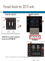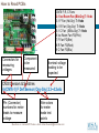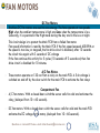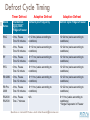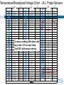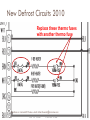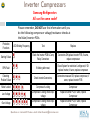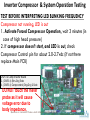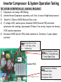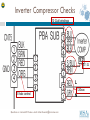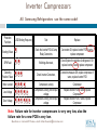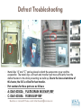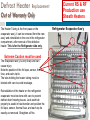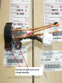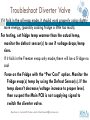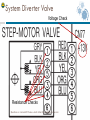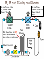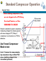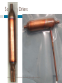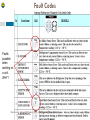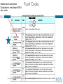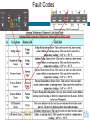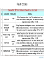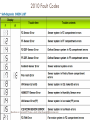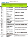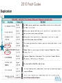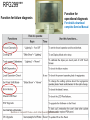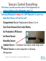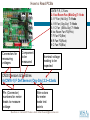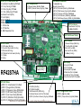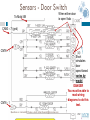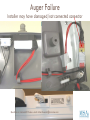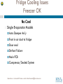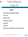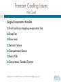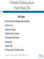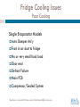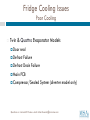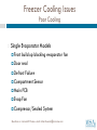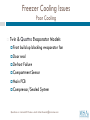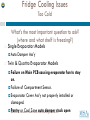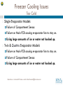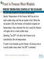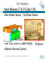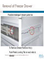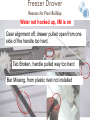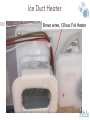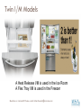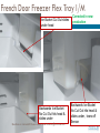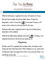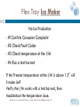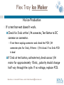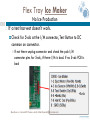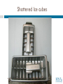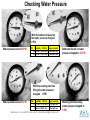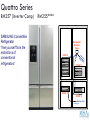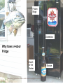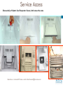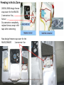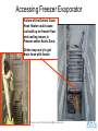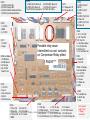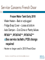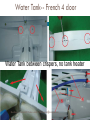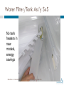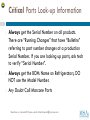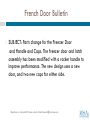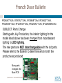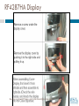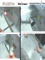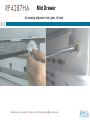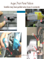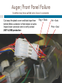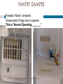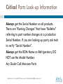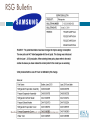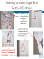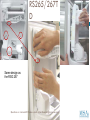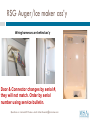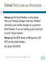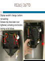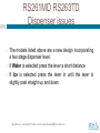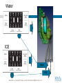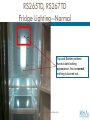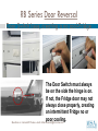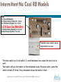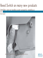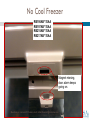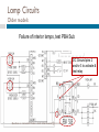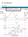
1
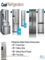
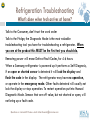
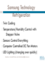
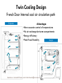
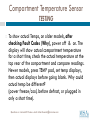
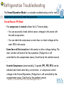
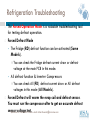
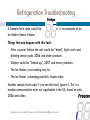
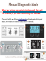
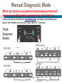
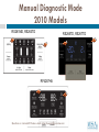
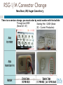
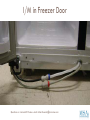
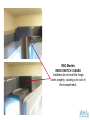
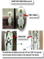
SAMSUNG REFRIGERATOR TRAINING Brought to you by: www.msaworld.com Presented by: Rick Kuemin, MSA Training Director Refrigerators Refrigerator Model Number Nomenclature • RF = French Door • RS = Side by Side • RB = Bottom Mount Freezer • RM = Four Door Questions or comments? Please e-mail [email protected] Samsung HA Warranty • ALL Warranties are subject to change, always verify. 1 Year Parts & Labor Base Warranty, Labor may not apply over 1 year Some items may have longer Warranties, Check Owners Manual or 800-SAMSUNG Refrigerator Sealed System Five Years Parts & Labor Laundry 2 years on Control Boards, 3 years on Stainless tubs, 10 years on DD washer motors M/W oven 10 years on Magnetron Tubes Range 5 years on Glass Cooktop and Radiant Surface Units D/W 5 years Printed Circuit Board, Racking and Lifetime Stainless Door Liner & Tub for leakage. No Damage Warranty, Consumer or Stock One Year, One Call for Consumer Education Stock Repair, 24 months from date of manufacture Two Stock Repairs allowed under Warranty Questions or comments? [email protected] Refurbished ProductPlease hase-mail no Warranty Refrigeration Troubleshooting RESULTS TEST What’s done when tech arrives at home? ASK Talk to the Consumer, don’t trust the work order Talk to the Fridge, the Diagnostic Mode is the most valuable troubleshooting tool you have for troubleshooting a refrigerator. When you are at the product this MUST be the first test you should do. Removing power will erase Defrost Fault Codes, for 4-6 hours. When a Samsung refrigerator is powered up it performs a Self Diagnosis, if an open or shorted sensor is detected it will lock the display and flash the code in the display. The refrigerator may have no operation, or operate in the emergency mode. Other faults detected will usually not lock the display or stop operation. To restart operation put into Manual Diagnostic Mode. Sensors that are off value, but not shorted or open, will not bring up a fault code. Questions or comments? Please e-mail [email protected] Samsung Technology Refrigeration Twin Cooling Temperature/Humidity Control with Stepper Valve Sensors Control Everything Computer Controlled DC Fan Motors LED Lighting (changing over quickly) Questions or comments? Please e-mail [email protected] Twin Cooling Design French Door Internal cool air circulation path Advantages •More accurate control of temperatures •No air exchange between compartments •Energy efficiency •Fresh Food Humidity Questions or comments? Please e-mail [email protected] Compartment Temperature Sensor TESTING To show actual Temps, on older models, after checking Fault Codes (Why), power off & on. The display will show actual compartment temperature for a short time, check the actual temperature at the top rear of the compartment and compare readings. Newer models, press TEMP pad, set temp displays, then actual displays before going blank. Why could actual temp be different? (power freeze/cool, before defrost, or plugged in only a short time). Questions or comments? Please e-mail [email protected] Refrigeration Troubleshooting RESULTS TEST The Forced Operation Mode is a valuable troubleshooting tool for testing compressor operation & some fan operation. Forced Freeze (FF) Mode • The compressor is started without the 5-7 minute delay You can accurately check defrost sensor voltages in this mode with the cold evaporators. You can check the compressor current draw or check voltage at the main PCB in this mode. • Some fans will be turned on in this mode, to allow voltage testing. The door switches still control the fan operation. (Fridge fan is still controlled by the compartment sensor, Cond fan by the ambient sensor) . • Inverter Compressors (most models), 3 speeds (FF1, FF2, FF3) can be selected and check some fans, current draw or compressor control voltage in the Forced Operation. (Fridge fan is still controlled by the compartment sensor, Cond fan by the ambient sensor) Questions or comments? Please e-mail [email protected] ASK RESULTS Refrigeration Troubleshooting TEST The Forced Operation Mode is a valuable troubleshooting tool for testing defrost operation. Forced Defrost Mode • The Fridge (RD) defrost function can be activated (Some Models). You can check the Fridge defrost current draw or defrost voltage at the main PCB in this mode. • All defrost function & Inverter Compressors You can check All (FD) defrost current draw or All defrost voltages in this mode (All Models). Forced Defrost will warm the evap coil and defrost sensor. You must run the compressor after to get an accurate defrost sensor Questionsvoltage or comments?test. Please e-mail [email protected] ASK Refrigeration Troubleshooting The Forced Operation Mode “Display” Inverter compressor models will show the forced function in the display FF1, FF2, FF3, FD (all defrost). Most standard compressor models manufactured after 2007 will show the forced function in the display FF, RD, FD Most models 2006 and older will have a blank display during the forced mode, wait 5 seconds between button pushes so you know what mode you are in (FF, RD, FD). If in doubt, unplug unit and start over. Questions or comments? Please e-mail [email protected] Forced Operation- Standard Compressors For Test Mode Press both buttons simultaneously ‘till it beeps and goes blank! Should be silent when two buttons are pushed simultaneously, any sound --start over Cancellation, unplug unit Wait 5 seconds between button pushes Press Freezer button One time at the Test Mode to Force Compressor Forced Compressor Press Freezer button Second time for Forced Defrost of Fridge Forced Defrost for Fridge Questions or comments? Please e-mail [email protected] Press Freezer button a third time to Force Defrost for Fridge & Freezer Forced Defrost for both compartment Inverter Compressor Forced Mode Press Freezer button One time at the Test Mode to Force each Compressor test then-- Forced Compressor High Forced Compressor Mid Forced Compressor Low For Test Mode Press both buttons simultaneously for 8 seconds! Wait 5 seconds between button pushes Simultaneous manual defrost (fresh food and freezer compartments) function Press Freezer button a 4th time to Force Defrost for ALL Compartments Questions or comments? Please e-mail [email protected] Forced Defrost for ALL compartments Forced Mode for Single Evap units Use Freezer Key as a Test Key Wait 5 seconds between button pushes RS2530** Questions or comments? Please e-mail [email protected] Forced Mode for 2010 units RS261MD, RS263TD RS265TD, RS267TD RS263TD is an inverter compressor, but will only do FF, RD, FD Questions or comments? Please e-mail [email protected] FF1, FF2, FF3, FD RF4287HA How to Read PCBs CN76 F, R, C Fans 2-1 Ice Room Fan (Blk-Gry)7-11vdc 3-1 F Fan (Yel-Gry) 7-11vdc 4-1 R Fan (Org-Gry) 7-11vdc 5-1 C Fan (S/Blu-Gry) 7-11vdc 6 Ice Room Fan FG(Pnk) 7 F Fan FG(Brn) 8 R Fan FG(Red) 9 C Fan FG(Blu) Connectors for measuring voltages Component to be measured Nominal voltage reading to be expected CN30 Sensors & Switches 4-(CN76-1) F Def Sensor (Org-Gry) 2.3~4.2vdc Pin (Connector) numbers for meter leads to measure voltage Wire colors for meter leads test points Questions or comments? Please e-mail [email protected] FAN MOTORS RESULT S TEST ASK DC Fan Motors Brushless DC Fan motors are used to save energy. The fans operate at two speeds. High when the ambient temperature is high and Low when the temperature is low. Generally, it is operated in the High mode during the day and in the Low at night. This circuit design is to protect the Main PCB from a failed fan motor. Fan speed information is read by the Main PCB. If the fan speed exceeds 600 RPM or the speed is too slow, or stopped, the fan drive circuit is disabled, after 10 seconds the circuit tries again with 3 seconds of DC voltage If the fan continues this activity for 5 cycles (10 seconds off 3 seconds on) then fan drive circuit is disabled for 10 minutes. A/C Fan Motors These motors operate on 120 vac from a relay on the main PCB. A 5 dc voltage is switched on and off by the door switch for the main PCB to activate the fan relays Compartment Fan A/C fan motors. With a closed door switch the sensor calls for cold and activates the relay, (delayed from 10 – 60 seconds). DC fan motors. With a closed door switch the sensor calls for cold and the main PCB activates the DC voltage to the motor, (delayed from 10 – 60 seconds). Questions or comments? Please e-mail [email protected] Defrost Cycle Timing Timer Defrost Adaptive Defrost Adaptive Defrost Model Series First Defrost Cycle, Both Fridge & Freezer Defrost Cycle Fridge only Defrost Cycle Fridge & Freezer RSG 6 hrs, Pause Time 10 minutes 6~12 hrs (varies according to conditions) 12~24 hrs (varies according to conditions) RS 4 hrs, Pause Time 10 minutes 6~12 hrs (varies according to conditions) 12~24 hrs (varies according to conditions) RF 6 hrs, Pause Time 12 minutes 6~17 hrs (varies according to conditions) 12~34 hrs (varies according to conditions) RFG 6 hrs, Pause Time 12 minute 6~11 hrs (varies according to conditions) 12~23 hrs (varies according to conditions) RB 2009 6 hrs, Pause Time 12 minutes 6~11 hrs (varies according to conditions) 12~23 hrs (varies according to conditions) RB Pre 2009 4 hrs, Pause Time 10 minutes 6~11 hrs (varies according to conditions) 12~22 hrs (varies according to conditions) RS2630 RS2530 4 hrs, Pause Time 7 minutes N/A 6~11 hrs (varies according to conditions) * Single Evaporator in Freezer Questions or comments? Please e-mail [email protected] Defrost Operation All new production (except RB series) uses Sheath Heaters Defrost cycle is initiated by the main PCB. 120vac is supplied to the defrost heater circuits, for the Fridge and/or for the Freezer After 90 seconds, the heaters remain on until the defrost sensor voltage tells the PCB to terminate the cycle. The PCB shuts off the heater at Sensor temps 50F in Freezer, and 63F in Fridge, after the main PCB initiates the cycle. The Thermal Fuse and/or Bi-Metal is the fail safe for this circuit The Thermal Fuse or Bi-Metal is in series with the defrost heater for protection (140 degree) for failure. Questions or comments? Please e-mail [email protected] Sensor Common Questions or comments? Please e-mail [email protected] Sensor Common Questions or comments? Please e-mail [email protected] Temperature/Resistance/Voltage Chart - ALL Fridge Sensors Ø Temp. (℉) ☺ Ø ☺ Resistance(㏀) Voltage (V) Temp. (℉) Resistance (㏀) Voltage (V) -43.6 -41.8 -40.0 -38.2 -36.4 -34.6 -32.8 -31.0 -29.2 -27.4 -25.6 -23.8 -22.0 -20.2 -18.4 16.6 -14.8 -13.0 -11.2 -9.40 -7.60 -5.80 -4.00 -2.20 -0.40 1.40 3.20 5.00 6.80 8.60 10.4 Questions 98.9 4.54 93.7 4.52 88.9 4.49 84.2 4.47 79.8 4.44 75.7 4.42 71.8 4.39 68.2 4.36 64.7 4.33 61.5 4.30 58.4 4.27 55.6 4.24 52.8 4.20 50.2 4.17 47.8 4.13 45.5 4.10 43.3 4.06 41.2 4.02 39.2 3.99 37.4 3.95 35.7 3.91 34.0 3.86 32.4 3.82 30.9 3.78 29.5 3.73 28.1 3.69 26.9 3.64 25.7 3.60 24.5 3.55 23.4 3.50 or22.4 comments? 3.46 Please Temp. (℉) 12.2 21.4 3.41 68.0 14.0 20.5 3.36 69.8 15.8 19.6 3.31 71.6 17.6 18.7 3.26 73.4 19.4 17.9 3.21 75.2 21.2 17.2 3.16 77.0 23.0 16.4 3.11 78.8 24.8 15.7 3.06 80.6 26.6 15.1 3.01 82.4 28.4 14.5 2.96 84.2 30.2 13.9 2.90 86.0 32.0 13.3 2.85 87.8 33.8 12.7 2.80 89.6 35.6 12.2 2.75 91.4 37.4 11.7 2.70 93.2 39.2 11.3 2.65 95.0 41.0 10.8 2.60 96.8 42.8 10.4 2.55 98.6 44.6 10.0 2.50 100.4 46.4 9.60 2.45 102.2 48.2 9.20 2.40 104.0 50.0 8.80 2.35 105.8 51.8 8.50 2.30 107.6 53.6 8.20 2.25 109.4 55.4 7.90 2.20 111.2 57.2 7.60 2.15 113.0 59.0 7.30 2.10 114.8 60.8 7.00 2.06 116.6 62.6 6.70 2.01 118.4 64.4 6.50 1.97 120.2 [email protected] 6.20 1.92 e-mail Table A A sensor reading 0.98 when cold may read 1.67 at room temp. Test VDC with comp running Ø ☺ Resistance (㏀) Voltage (V) 6.01 5.79 5.58 5.38 5.19 5.00 4.82 4.65 4.49 4.33 4.18 4.03 3.89 3.76 3.63 3.51 3.39 3.28 3.17 3.06 2.96 2.86 2.77 2.68 2.59 2.51 2.43 2.35 2.28 2.21 1.88 1.83 1.79 1.75 1.71 1.67 1.63 1.59 1.55 1.51 1.47 1.44 1.40 1.37 1.33 1.30 1.27 1.23 1.20 1.17 1.14 1.11 1.09 1.06 1.03 1.00 0.98 0.95 0.93 0.90 RESULTS Defrosting Troubleshooting TEST Testing Defrost Circuits – Always test all compartments, even if only Defrost Sensor one is bad. 1. Access main PCB for voltage/resistance testing 2. With the compressor running, test the defrost sensors (vdc) 3. Enter Forced Mode Defrost 4. Measure heater voltage 5. Remove power and heater connector and check heater circuit resistance ASK After 90 seconds, the sensor voltage shuts off heater, at 50 in Freezer, 63 in Fridge If the sensor is bad it may shut off the defrost circuit in a few minutes, after the initial 90 seconds, causing frost build-up, or it could lock up in defrost and become a total no cool. Note: A defective sensor may check OK at room temperature, test at operating temperature only. •Questions or comments? Please e-mail [email protected] Defrosting Troubleshooting Heater is part of Evap Coil (RB & older production) Pins 7-9 = 2,880Ω What’s Wrong? Pins 7-9 = ∞ What’s Wrong? 58Ω 320Ω 103Ω 2,880Ω Questions or comments? Please e-mail [email protected] Sample Heater Resistances Older RB Models Component Resistance Wattage Voltage Freezer Defrost Heater 60Ω 242 120vac Fridge Defrost Heater 120Ω 120 120vac Freezer Drain Heater 277Ω 52 120vac Fridge Drain Heater 379Ω 38 120vac Fill Tube Heater 1100Ω 10 120vac New RB Models Component Resistance Wattage Voltage Fridge Defrost Heater 120Ω 120 120vac Freezer Defrost Heater 60Ω 240 120vac Go to Fridge Fast Tracks for each Model RF & RFG Models Component Resistance Wattage Voltage Freezer Defrost Heater 60Ω 240 120vac Fridge Defrost Heater 120Ω 120 120vac French Mullion Heater 1800Ω 8 120vac Ice Duct Heater 3600Ω 4 120vac Dispenser Heater 9000Ω 1.6 120vac Water Tank Heater 72Ω 2 12vdc Fill Tube Heater 72Ω 2 12vdc RM Models Component Resistance Wattage Voltage Freezer Defrost Heater 72Ω 200 120vac Older RS Models c Fridge Defrost Heater 180Ω 80 120vac Component Resistance Wattage Voltage CF Defrost Heater 144Ω 100 120vac Freezer Defrost Heater 58Ω 215 120vac CR Defrost Heater 180Ω 80 120vac Fridge Defrost Heater 103Ω 140 120vac F Drain Tube/Heater 2880Ω 5 120vac Freezer Drain Heater 320 45 120vac R Drain Tube/Heater 2880Ω 5 120vac Dispenser Heater 2880Ω 5 120vac Dispenser Heater 2880Ω 5 120vac Water Tank Questions Heater 3600Ω 120vac or comments? Please4 e-mail [email protected] Water Tank Heater 29Ω 5 12vdc Fill Tube Heater 2880Ω 5 120vac Fill Tube Heater 29Ω 5 12vdc Fill Tube 1108Ω 13 120vac Defrosting Troubleshooting RESULTS TEST Heater is part of Evap Coil (RB & older production) Resistance and use vary by Model (See Fast Track) 2800 to 120 ohm heaters – 380 ohm heater Questions or comments? Please e-mail [email protected] RB series only ASK New Defrost Circuits 2010 Replace these thermo fuses with another thermo fuse Questions or comments? Please e-mail [email protected] Inverter Compressors on new units Questions or comments? Please e-mail [email protected] Inverter Compressors Samsung Refrigerators All use the same code!! Please remember, DO NOT use this information until you do the following compressor voltage/resistance checks at the Main/Inverter PCBs Protection Functions Test Replace Starting Failure Check the Inverter PCB & Comp Relay Connectors Connectors OK,replace Inverter PCB, if same, replace compressor SPM Fault If blinking after reset, Check System for restriction & refrigerant, if OK replace Inverter, if same, replace compressor Detecting Position Failure Check Inverter Connectors, Connectors measure OK, replace compressor, if same, replace Inverter PCB Motor Locked Compressor Locking Compressor Compressor Locking, check input voltage Compressor Locking, check input voltage Replace Inverter PCB, if same, replace Compressor Replace Inverter PCB, if same, replace Compressor Low Voltage Over Voltage LED Blinking Frequency Questions or comments? Please e-mail [email protected] Inverter Compressor & System Operation Testing TEST BEFORE INTERPRETING LED BLINKING FREQUENCY Compressor not running, LED is out 1. Activate Forced Compressor Operation, wait 3 minutes (in case of high head pressure) 2. If compressor doesn’t start, and LED is out, check Compressor Control pin for about 2.0-2.7vdc (if not there replace Main PCB) CN75 To Comp Inverter Board 2- ( CN76-1) (Brn-Gry) 5vdc 4- ( CN76-1) Comp control (Org-Gry) 2.5vdc DO NOT touch the meter probe as it will cause voltage error due to body impedance. Questions or comments? Please e-mail [email protected] Inverter Compressor & System Operation Testing TEST BEFORE INTERPRETING LED BLINKING FREQUENCY 1) Compressor not running--LED Blinking 2) Activate Forced Compressor operation, wait 3 min. (in case of high head pressure) 3) Check for 120vac at CN02 Red and Gray wires. 4) If voltage is OK, remove power, disconnect CN03 (Inverter PCB) and check resistance to the windings. Aproxametly10 ohms. If not correct , inspect wire harness, if OK replace compressor. 5) Disconnect CN02 (Inverter PCB), check resistance to Overload , if open replace overload. CN02 Overload & A/C Line 1 OLP - 3 OLP (Brn- S/Blu) 3 L - 1 N (Red-Gry) CN04 Compressor Control 2- (CN76-1) 5vdc (Brn-Gry) 4 Comp Signal (Org) LED Inverter PCB Questions or comments? Please e-mail [email protected] CN03 Compressor Windings 1 Compressor (Blue) 3 Compressor (Prp) 5 Compressor (Wht) Inverter Compressor Checks RESULTS TEST ASK 10 Ω all windings 0.1 Ω L 120vac 2.5vdc control Questions or comments? Please e-mail [email protected] N Inverter Compressors All Samsung Refrigerators use the same code! Protection Functions LED Blinking Frequency Test Replace Starting Failure Check the Inverter PCB & Comp Relay Connectors Connectors OK,replace Inverter PCB, if same, replace compressor SPM Fault If blinking after reset, Check System for restriction & refrigerant, if OK replace Inverter, if same, replace compressor Detecting Position Failure Check Inverter Connectors, Connectors measure OK, replace compressor, if same, replace Inverter PCB Motor Locked Compressor Locking Compressor Compressor Locking, check input voltage Compressor Locking, check input voltage Replace Inverter PCB, if same, replace Compressor Replace Inverter PCB, if same, replace Compressor Low Voltage Over Voltage Note: Failure rate for inverter compressors is very very low, also the failure rate for a new PCB is very low. Questions or comments? Please e-mail [email protected] SPEEDY DEFROST Questions or comments? Please e-mail [email protected] T O O L S Defrost Troubleshooting NOTE: Evaporator Covers May Break or Crack if Removed While Frozen To Coil, replace if damaged. Ice build up in either the freezer or refrigerator compartment can be caused by a blocked drain. It is possible that the drain is not being defrosted by the heaters enough to properly clear the drain and pass the melted water into the catch pan. In the Freezer compartment this may be caused by an open defrost foil drain heater In the Fridge compartment this may be caused by a bowed or damaged evaporator cover ass’y. Any cracks in Styrofoam or breaks in the foil will cause ice buildup. Check drain tubes next to condenser coil. Questions or comments? Please e-mail [email protected] Defrost Troubleshooting Metal clips “A” and “C” can be placed on both the evaporator cover and the evaporator. The metal clips will touch and transfer heat more efficiently from the defrost heaters to the drain preventing ice build up. Due to the low current draw of this heater, the foil is critical for heat transfer. Part numbers for these parts are as follows: A: DA61-03502A PLATE-DRAIN INS EVAP, REF C: DA61-03585A FIXER-EVAP REF Questions or comments? Please e-mail [email protected] Defrost Heater Replacement Out of Warranty Only The Heater Tubing is the front pass on the evaporator ass’y, it can be removed from the new ass’y and reinstalled on the one in the refrigerator compartment, after removal of the defective heater. This is for the Refrigerator side only. Extreme Caution must be used The Evaporator ass’y is very sharp and can cause injury. Note the position of the foil tape, sensor, thermal fuse, and each zip tie. The tabs holding the heater tubing must be twisted with care to avoid breakage. Reinstallation of the heater on the refrigerator evaporator must be done with care to prevent defrost drain freezing issues. Lock each tab properly to assist in heat transfer and position the foil tape, sensor, thermal fuse, and each zip tie exactly as removed. Straighten all fins Current RS & RF Production use Sheath Heaters Refrigerator Evaporator Ass’y Tools required Kevlar Gloves Foil Tape Zip Ties Long Nose Pliers Cutter Drill Pop Rivet tool Heater aluminum tube is locked to the evaporator frame with two tabs on each pass. Twist each tab carefully to avoid breakage and lift up heater tubing. Questions or comments? Please e-mail [email protected] Drain Tray is riveted to the evaporator frame Drill out rivet to separate heater/tray ass’y from the evaporator coil. Use Pop Rivet tool to reinstall on evaporator ass’y in the refrigerator. Heater Ass’y after separation from the evaporator coil Questions or comments? Please e-mail [email protected] Electrical and system parts can be changed separately. Questions or comments? Please e-mail [email protected] Troubleshoot Diverter Valve RESULTS TEST ASK If it fails in the all evap mode, it should work properly using slightly more energy, (possibly cooling fridge a little too much). For testing, set fridge temp warmer than the actual temp, monitor the defrost sensor(s) to see if voltage drops/temp rises. If it fails in the Freezer evap only mode, there will be a Fridge no cool Force on the Fridge with the “Pwr Cool” option. Monitor the Fridge evap(s) temp by using the Defrost Sensor(s). If the temp doesn’t decrease/voltage increase to proper level, then suspect the Main PCB is not supplying signal to switch the diverter valve. Questions or comments? Please e-mail [email protected] System Diverter Valve RESULTS TEST ASK Voltage Check Resistance Checks Questions or comments? Please e-mail [email protected] RB, RF and RS units, non Diverter No Cool Freezer, Fridge OK, can it be Sealed System? Why? Side Cluster Pipes Get HOT Space required at sides, back and top on most models Questions or comments? Please e-mail [email protected] No Cool Fridge, Freezer OK, can it be Sealed System? Why? Standard Compressor Operation Special Note: • When ordering compressors, they are not shipped with a PTC Relay, Overload Protector, or Drier. REMEMBER TO ORDER! Neutral is switched to power compressor, measuring voltage from chassis ground will show voltage at PTC Relay if compressor is not turned on or PCB is defective. Use Forced Compressor Mode to test. Use L1 Common for measurements, tap compressor relay on Main PCB Questions voltage or comments? when checking toPlease finde-mail [email protected] intermittent problems. 120vac when relay closed RESULT S TEST ASK Samsung Driers Questions or comments? Please e-mail [email protected] Refrigeration Troubleshooting A Sample fault code would be Ice Maker Sensor failure. This is an example of an Things that can happen with this fault. • After a power failure the unit would be “dead”, lights work and blinking sensor code, 2006 and older products • Display could be “locked-up”, 2007 and newer products • The Ice Maker is not making any ice • The Ice Maker is dumping partially frozen cubes Another sample fault code, if you see this fault, ignore it. This is a modem communication error not applicable in the US, found on units 2006 and older. Questions or comments? Please e-mail [email protected] Manual Diagnostic Mode When two buttons are pushed simultaneously there will be no sound, if you hear a sound stop and start over. Press and hold the two Buttons simultaneously until display quits blinking and beeps, then release and read fault codes, about 8-10 seconds. Questions or comments? Please e-mail [email protected] Manual Diagnostic Mode When two buttons are pushed simultaneously there will be no sound, if you hear a sound stop and start over. Press and hold the two Buttons simultaneously until display quits blinking and beeps, then release and read fault codes, about 8-10 seconds. Single Evaporator Models Questions or comments? Please e-mail [email protected] Manual Diagnostic Mode 2010 Models RS261MD, RS263TD RS265TD, RS267TD RF4287HA Questions or comments? Please e-mail [email protected] Fault Codes Faults possible when working on a unit. WHY? Questions or comments? Please e-mail [email protected] Master fault code sheet Duplications are always RM 4door units Fault Codes 4-Door 4-Door 4-Door 4-Door 4-Door Questions or comments? Please e-mail [email protected] Fault Codes Questions or comments? Please e-mail [email protected] Fault Codes Questions or comments? Please e-mail [email protected] 2010 Fault Codes Questions or comments? Please e-mail [email protected] 2010 Fault Codes Questions or comments? Please e-mail [email protected] 2010 Fault Codes Duplication Questions or comments? Please e-mail [email protected] RFG299*** Function for failure diagnosis Function for operational diagnosis For details download complete Service Manual Questions or comments? Please e-mail [email protected] Sensors Control Everything The Sensors provide accurate control of the temperatures at various locations in the refrigerator, (up to 11). Samsung Refrigerators always do a Self Diagnostic on power up, Open/Short Sensor will lock the unit! • • Compartment (Room) Temperature Sensor 2 or 4 Cool Zone Drawer/Cool select Pantry Ice Production I/M Sensor Ice Room Sensor Humidity Sensor Ambient Sensor – Condenser Fan control, under hinge cover Defrost Sensors on each evaporator in Samsung Refrigerators Questions or comments? Please e-mail [email protected] How to Read PCBs CN76 F, R, C Fans 2-1 Ice Room Fan (Blk-Gry)7-11vdc 3-1 F Fan (Yel-Gry) 7-11vdc 4-1 R Fan (Org-Gry) 7-11vdc 5-1 C Fan (S/Blu-Gry) 7-11vdc 6 Ice Room Fan FG(Pnk) 7 F Fan FG(Brn) 8 R Fan FG(Red) 9 C Fan FG(Blu) Connectors for measuring voltages Component to be measured Nominal voltage reading to be expected CN30 Sensors & Switches 4-(CN76-1) F Def Sensor (Org-Gry) 2.3~4.2vdc Pin (Connector) numbers for meter leads to measure voltage Wire colors for meter leads test points Questions or comments? Please e-mail [email protected] CN76 F, R, C Fans & Door Sws 2-1 Ice Room Fan (Blk-Gry)7-11vdc 3-1 F Fan (Yel-Gry) 7-11vdc 4-1 R Fan (Org-Gry) 7-11vdc 5-1 C Fan (S/Blu-Gry) 7-11vdc 6 Ice Room Fan FG(Pnk) 7 F Fan FG(Brn) 8 R Fan FG(Red) 9 C Fan FG(Blu) 11– Fz Door Sw 12– FF Door Sw 13– Mid Drawer door Sw CN77 Stepper Motor 1-2 Damper Heater (Blk-Brn) 12vdc 7-(CN76-1) Diverter Valve (Org-Gry) 12vdc CN30 Sensors & Switches 2-1 +5vdc (Blk-Gry) 3 Humidity Sensor (Brn) 4-(CN76-1)Fz Sensor (Red-Gry) 3.5~4.2vdc 5-(CN76-1)F Def Sensor (Org-Gry) 2.3~4.2vdc 6-(CN76-1) R Sensor (Wht-Gry) 2.4~2.8vdc 8-(CN76-1) R Def Sensor (S/Blu-Gry) 2~4.2vdc 9-(CN76-1) Mid Drawer Sensor (W/Blk-Gry) 2.6~2.8vdc CN79 Flow Sensor 7-Flow Sensor Out (Wht) 9-8 +5vdc (Red-Blk) CN51 Mid Drawer Display CN90 Ice Maker 1-7 Sensor I/M eject (Brn-Gry) 2-7 Test Sw (Blk-Gry) 5vdc 3 Full Hall IC out (Blu) 4 Horiz Hall IC out (S/Blu) 5-7 +5vdc (Yel-Gry) CN70 All 120vac 3-13 I/M Heater (Blk-Gry) 5-13 French & Disp Heater (Yel-Gry) 7-13 R Defrost (Wht-Org) 9-13 F Defrost/Ice Duct heater (Brn-Gry) 11- L1 (Red) 13- N (Gry) RF4287HA CN71 All 120vac 3 Neutral (Gray) CN73 All 120vac CN78 1-(CN70-11) Cube Solenoid (Yel-Red) 1-2 Fz LEDs (Brn-Prp) 3-(CN70-11) Auger Motor (Pnk-Red) 3-5 FF LEDs (Red-Blk) 5-(CN70-11) Dispenser Valve (W/Blk-Red) 6-7 Mid Drawer LED (W/Blk-Gry) 7-(CN70-11) I/M Valve Fridge (Prp-Red) 8-12 Ambient Sensor (Yel-Yel) 1.2~2 vdc 9-(CN70-11) Ice Cover Route (Blu-Red) 10-(CN76-1) Ice Room Sensor (Org-Gry) 3~3.8vdc 11-(CN70-11) I/M Motor CW (R) (Brn-Red) 13-(CN70-11) I/MQuestions Motor CCWor(R) (Wht-Red)Please e-mail [email protected] comments? CN50 Display 3-5 (Org-Yel) 13vdc 4-5 (Yel-Yel) 5vdc 7-5 Ice Sw (Blu-Yel) 5vdc 8-5 Water Sw (Pnk-Yel) 5vdc 9-5 Ice Rte Sw 1(Prp-Yel) 5vdc 10-5 Ice Rte Sw 2 (Wht-Yel) 5vdc CN75 To Comp Inverter Board 2-(CN76-1) (Brn-Gry) 5vdc 4-(CN76-1) Comp control (Org-Red) 2.5vdc Sensors - Door Switch To Mold I/M RESULTS TEST When either door is open 5vdc ASK CN50 – 7 (gnd) CN76 - 1 Short simulates door open/closed varies by model DANGER You must be able to read wiring diagrams to do this test. CN76 - 1 Questions or comments? Please e-mail [email protected] Auger Failure Installer may have damaged/not connected connector Questions or comments? Please e-mail [email protected] Testing Cube Solenoid & Auger Motor bypass the PCB DANGER You must be able to read wiring diagrams to do this test. Cube Solenoid & Auger Mtr are tied to L1 (Red), in most models. Remove power. To activate, Jumper Neutral, in most models, to the component, power unit and component activates RESULTS TEST ASK Questions or comments? Please e-mail [email protected] N L1 Temperature/Resistance/Voltage Chart - ALL Fridge Sensors Temp. (℉) Resistance(㏀) Voltage (V) Temp. (℉) Resistance (㏀) Voltage (V) -43.6 -41.8 -40.0 -38.2 -36.4 -34.6 -32.8 -31.0 -29.2 -27.4 -25.6 -23.8 -22.0 -20.2 -18.4 16.6 -14.8 -13.0 -11.2 -9.40 -7.60 -5.80 -4.00 -2.20 -0.40 1.40 3.20 5.00 6.80 8.60 10.4 Questions 98.9 4.54 93.7 4.52 88.9 4.49 84.2 4.47 79.8 4.44 75.7 4.42 71.8 4.39 68.2 4.36 64.7 4.33 61.5 4.30 58.4 4.27 55.6 4.24 52.8 4.20 50.2 4.17 47.8 4.13 45.5 4.10 43.3 4.06 41.2 4.02 39.2 3.99 37.4 3.95 35.7 3.91 34.0 3.86 32.4 3.82 30.9 3.78 29.5 3.73 28.1 3.69 26.9 3.64 25.7 3.60 24.5 3.55 23.4 3.50 or22.4 comments? 3.46 Please Temp. (℉) 12.2 21.4 3.41 68.0 14.0 20.5 3.36 69.8 15.8 19.6 3.31 71.6 17.6 18.7 3.26 73.4 19.4 17.9 3.21 75.2 21.2 17.2 3.16 77.0 23.0 16.4 3.11 78.8 24.8 15.7 3.06 80.6 26.6 15.1 3.01 82.4 28.4 14.5 2.96 84.2 30.2 13.9 2.90 86.0 32.0 13.3 2.85 87.8 33.8 12.7 2.80 89.6 35.6 12.2 2.75 91.4 37.4 11.7 2.70 93.2 39.2 11.3 2.65 95.0 41.0 10.8 2.60 96.8 42.8 10.4 2.55 98.6 44.6 10.0 2.50 100.4 46.4 9.60 2.45 102.2 48.2 9.20 2.40 104.0 50.0 8.80 2.35 105.8 51.8 8.50 2.30 107.6 53.6 8.20 2.25 109.4 55.4 7.90 2.20 111.2 57.2 7.60 2.15 113.0 59.0 7.30 2.10 114.8 60.8 7.00 2.06 116.6 62.6 6.70 2.01 118.4 64.4 6.50 1.97 120.2 [email protected] 6.20 1.92 e-mail Table A Resistance (㏀) Voltage (V) 6.01 5.79 5.58 5.38 5.19 5.00 4.82 4.65 4.49 4.33 4.18 4.03 3.89 3.76 3.63 3.51 3.39 3.28 3.17 3.06 2.96 2.86 2.77 2.68 2.59 2.51 2.43 2.35 2.28 2.21 1.88 1.83 1.79 1.75 1.71 1.67 1.63 1.59 1.55 1.51 1.47 1.44 1.40 1.37 1.33 1.30 1.27 1.23 1.20 1.17 1.14 1.11 1.09 1.06 1.03 1.00 0.98 0.95 0.93 0.90 Proper Splicing, when necessary Questions or comments? Please e-mail [email protected] Fridge Cooling Issues Freezer OK No Cool Single Evaporator Models Auto Damper Ass’y Frost in air duct to fridge Door seal Defrost Failure Main PCB Compressor/Sealed System Questions or comments? Please e-mail [email protected] Fridge Cooling Issues Freezer OK No Cool Twin & Quattro Evaporator Models Door seal Defrost Failure Defrost Drain Failure Main PCB Evap Fan Compressor/Sealed System (diverter models only) Questions or comments? Please e-mail [email protected] Freezer Cooling Issues No Cool Single Evaporator Models Frost build up stopping evaporator fan Evap Fan Door seal Defrost Failure Compartment Sensor Main PCB Compressor/Sealed System Questions or comments? Please e-mail [email protected] Freezer Cooling Issues Fresh Food OK No Cool Twin & Quattro Evaporator Models Door seal Defrost Failure Defrost Drain Failure Compartment Sensor Evap Fan Main PCB Compressor/Sealed System Questions or comments? Please e-mail [email protected] Fridge Cooling Issues Poor Cooling Single Evaporator Models Auto Damper Ass’y Frost in air duct to fridge No or very small food load Door seal Defrost Failure Main PCB Compressor/Sealed System Questions or comments? Please e-mail [email protected] Fridge Cooling Issues Poor Cooling Twin & Quattro Evaporator Models Door seal Defrost Failure Defrost Drain Failure Main PCB Compressor/Sealed System (diverter model only) Questions or comments? Please e-mail [email protected] Freezer Cooling Issues Poor Cooling Single Evaporator Models Frost build up blocking evaporator fan Door seal Defrost Failure Compartment Sensor Main PCB Evap Fan Compressor/Sealed System Questions or comments? Please e-mail [email protected] Freezer Cooling Issues Poor Cooling Twin & Quattro Evaporator Models Frost build up blocking evaporator fan Door seal Defrost Failure Compartment Sensor Main PCB Compressor/Sealed System Questions or comments? Please e-mail [email protected] Fridge Cooling Issues Too Cold What’s the most important question to ask? (where and what shelf is freezing?) Single Evaporator Models Auto Damper Ass’y Twin & Quattro Evaporator Models Failure on Main PCB causing evaporator fan to stay on. Failure of Compartment Sensor. Evaporator Cover Ass’y not properly installed or damaged. Questions Pantry or Cool Zone auto damper stuck open or comments? Please e-mail [email protected] Freezer Cooling Issues Too Cold Single Evaporator Models Failure of Compartment Sensor. Failure on Main PCB causing evaporator fan to stay on. Using large amounts of ice or water not hooked up. Twin & Quattro Evaporator Models Failure on Main PCB causing evaporator fan to stay on. Failure of Compartment Sensor. Using large amounts of ice or water not hooked up. Questions or comments? Please e-mail [email protected] Frost in Freezer Most Models FREEZER TEMPERATURE CONTROL BY THE ICE MAKER Very cold temps will cause frost in the freezer with door openings Interior Temperature of the freezer MAY be set to a much colder temp until the ice bucket is full. When the ice bucket is full, the freezer will maintain original set temperature. Also, whenever the ice is used, the freezer will again set to a much colder temp. Selecting "Ice Off” will allow the freezer to be controlled by the set temperature. If water is not hooked up, the freezer will always be at a much colder temp unless “Ice Off” is selected. Questions or comments? Please e-mail [email protected] Ice Makers RESULTS TEST Heat Release (7 & 9 Cube I/M) Ice ASK Maker Sensor / Ice Room Sensor Test Button Flex Tray (new 8 cube trays) Sensor Harvest Control Questions or comments? Please e-mail [email protected] I/M Sensor Ice/Auger Harness RESULTS TEST ASK Pull out harness to remove I/M Align to allow bucket fit Cover Screw Questions or comments? Please e-mail [email protected] Ice Room temp with an accurate temp gun, metal heat sink will hold temp for a short time. Ice/Auger Harness Cover Push to release tab, counter depth models Questions or comments? Please e-mail [email protected] Ice Makers RFG293HA French Door has the I/M in the freezer. It’s now a Heat Release I/M Questions or comments? Please e-mail [email protected] Heat Release Ice Maker Ice Production & Test Explanation 38 minutes after the water fill is complete, the control board will check the temperature of the eject Thermistor, on the Ice Maker Head. If the Thermistor reads a temperature lower than 18.5 degrees for more than 5 seconds, the Ice maker will harvest if the ice bucket is not sensed as full. Press and hold the ICE TEST S/W for at least 1.5sec, the harvest function will start. The Ice maker heater turns on for 30 seconds to 2 minutes. After the Ice maker heater turns off, the Ice maker harvest motor turns on. The motor will rotate in right direction for about 3 minutes, after this, water supply valve is turned on, then the valve is turned off, the test mode is completed. If the above operation is not carried out within 6 minutes, it will go into a fault mode. You must have patience, this is not as fast as the flex tray test cycle. Questions or comments? Please e-mail [email protected] Heat Release I/M French Door Ice Room Fan Operation RESULTS TEST ASK Making Ice Fan Off at 3.68vdc Ice Room Sensor 1.5F Fan On at 3.54vdc Ice Room Sensor 7F Full bucket, or ice off Fan Off at about 3.35vdc Ice Room Sensor 14.5F Fan On at about 2.91vdc Ice Room Sensor 29F Questions or comments? Please e-mail [email protected] Heat Release I/M Testing RESULTS TEST All Tests must be done before the Ice Bucket is removed and with the compressor running. Ice Room Sensor – record voltage and convert to temp. Ice Maker Eject Sensor - record voltage and convert to temp. Ice Room Fan – 7-11 vdc – is it OK? proper voltage means motor speed is correct. Freezer Defrost Sensor - record voltage and convert to temp. If Ice Bucket is full, fan may be off, Ice Room and I/M Sensor may be around 23°. When making ice, the Ice Room should be around 6°. The I/M Sensor will be above 18°. The Ice Room Fan may be running. With the compressor running the Freezer Defrost Sensor should be around -10°. Questions or comments? Please e-mail [email protected] ASK No, Slow and/or “wet” ice RESULTS TEST ASK Door adjust is too low or bent hinge. Carefully inspect hinge for damage (bending) before adjusting door, replace if necessary. Use this part # to raise door height DA60-00143B Description : FASTENER-RING INSERT Consumer could get water in the glass when getting ice from condensation in chute. What if consumer uses only Crushed Ice? Water in the chute from melting “snow”. Questions or comments? Please e-mail [email protected] Service Concerns Heat Release I/M Troubleshooting Observations Is there any frost in the freezer compartment? Excessive frost on the evaporator coil will either coat the coil enough to warm the air to 32 degrees to supply the ice room or block the air duct completely to the ice room. Make sure the Freezer defrost circuit is working properly and the freezer and ice room compartments are sealed properly The Ice-Duct Heater is a foil heater the keeps the duct, on the evaporator cover, from frosting up and blocking air flow to the I/M. If this heater fails there will be low or no ice production. Questions or comments? Please e-mail [email protected] Removal of Freezer Drawer Possible breakage if drawer pulled too hard To Remove Drawer Rail/Door Ass’y Push Plastic Locking Tab on each side to Questions or comments? Please e-mail [email protected] release. Freezer Drawer Reasons for Frost Buildup Water not hooked up, I/M is on RESULTS TEST Gear alignment off, drawer pulled open from one side of the handle too hard. Tab Broken, handle pulled way too hard Bar Missing, from plastic rivet not installed Questions or comments? Please e-mail [email protected] ASK Ice Duct Heater RESULTS TEST ASK Brown wires, 120vac Foil Heater Questions or comments? Please e-mail [email protected] Twin I/M Models A Heat Release I/M is used in the Ice Room A Flex Tray I/M is used in the Freezer Questions or comments? Please e-mail [email protected] Model : RFG298AA**/XAA Dual Ice Maker nominal voltages listed CN31 Sensor 1-4 Ambient Sensor (Wht-Wht) 1.2~2 vdc 2-(CN90-8) I/M (Blu-S/Blu) 5vdc 3-(CN76-1) Ice Room Sensor (Org-Gry) 3~3.8vdc CN78 Lamp/Veg LED 4-7 (Red-Gry) 13vdc CN74 A/C Load 120vac 1-(CN70-9) Cube Solenoid (Yel-Red) 3-(CN70-9) Auger Motor (Pnk-Red) 5-(CN70-9) Dispenser Valve (W/Blk-Red) 7-(CN70-9) I/M Valve Fridge (Prp-Red) 9-(CN70-9) Ice Cover Route (Blu-Red) 11-(CN70-9) I/M Motor CW (R) (Brn-Red) 13-(CN70-9) I/M Motor CCW (R) (Wht-Red CN72 A/C Load120vac 5-(CN70-9) Ice Maker Valve Frz (Brn-Red) CN77 Stepper Motor 1-( CN76-1) (Red-Gry) 13vdc CN91 Pantry Room Damper 1-2 Damper Heater (Blk-Brn) 12vdc 3-4 Damper Motor (Wht-Blu) 5-6 Damper Motor (Yel-Red) CN90 Ice Maker 1-2 I/M Mtr Frz (Red-Blk) 13vdc 3-4 Eject Sensor Frz(Wht-Wht) 2.1~3.7vd CN71 A/C Load 120vac 3-(CN70-9) F Lamp (Prp-Red) 5 N (Gray) 9 Heater Common (Org) CN70 A/C Load 120vac 1-11 I/M Heater (Blk-Gry) 3-11 French-Dsp Heaters (Yel-Gry) 5- (CN71-9) R Defrost (Wht-Org) 7- (CN71-9) F Defrost/Ice Duct heater (Brn-Org) 9- L1 (Red) 11- N (Gry) CN50 Display 4-6 (Org-Pnk) 13vdc 5-6 (Yel-Pnk) 5vdc 7 Fridge Door Sw (Gry) (vdc ground) 8-6 Ice/Water Sw (Blu-Pnk) 5vdc 9-6 Ice Rte Sw 1(Prp-Gry) 5vdc 10-6 Ice Rte Sw 2 (Wht-Gry) 5vdc 11 Fridge I/M Horiz Sw (S/Blu) 5vdc CN76 F, R, C Fans 2-1 Ice Room Fan (Blk-Gry)7-11vdc 5-8 Test Sw Frz (Gry-S/Blu) 5vdc 6 Full Hall IC Fridge I/M (Blu) 7 Horiz Hall IC Frz (Prp) 8 Ground vdc (S/Blu) 3-1 F Fan (Yel-Gry) 7-11vdc 4-1 R Fan (Org-Gry) 7-11vdc 5-1 C Fan (S/Blu-Gry) 7-11vdc 6 Ice Room Fan FG(Pnk) 7 F Fan FG(Brn) 8 R Fan FG(Red) 9 C Fan FG(Blu) CN51 Pantry Room 7-5 (Blu-Wht) 13vdc CN30 Sensors & Switches 1-5 Freezer Dr Sw (Blk-Gry) 5vdc 2-(CN50-7) R Door Sw (Prp-Gry) 5vdc CN32 Flow Sensor (Frz I/M) 3-2 (Red-Blk) 5vdc CN75 To Comp Inverter Board 1- ( CN76-1) Test Sw Fridge I/M (Blk-Gry) 2- ( CN76-1) (Brn-Gry) 5vdc Questions or comments? 4-3 Compressor control (Org-Red) 2.5vdc RED=I/M 3-(CN76-1) F Sensor (Red-Gry) 3.5~4.2vdc Please CN79 4-(CN76-1) F Def Sensor (Org-Gry) 2.3~4.2vdc 2-7 Fill tube heater 6-(CN76-1) R Sensor (Wht-Gry) 2.4~2.8vdc freezer (Blu-Wht) 13vdc 7-(CN76-1) Eject Sensor Fridge I/M (Brn-Gry) 2.1~3.3vdc 3-7 Water Tank 8-(CN76-1) R Def Sensor (S/Blu-Gry) 2~4.2vdc e-mail [email protected] Htr (Pnk-Wht) 13vdc 9- (CN76-1) Pantry Sensor (W/Blk-Gry) 2.6~2.8vdc French Door Freezer Flex Tray I/M Ice Bucket Cut Out slides under head Backwards Ice Bucket No Cut Out hits head & slides under Questions or comments? Please e-mail [email protected] Corrected in new production Backwards Ice Bucket No Cut Out hits head & slides under , tears off Sensor Flex Tray Ice Maker Ice production Explanation When the initial power is applied, the ice tray will stand by for 2 hours. After the 2-hour standby time, the Ice Maker Sensor will check the temperature , when it is lower than 1.5℉ for more than 5 minutes, it will harvest, with or without ice in the tray, then fill with water. 58 minutes after water is supplied to the Ice Tray, the Ice Maker Sensor temperature will be checked. When the Ice Maker Sensor maintains lower than 1. 5℉ for 5 minutes, it will completes the harvest, if the ice bin is not sensed as full. Filling the tray After the water fill is completed, the ice maker sensor will evaluate water volume, one and a half minutes later. When it detects no or low water level it will add more water. First supply time will be 1.5 sec, next one will be 1 sec and the last will be 2 sec. Questions or comments? Please e-mail [email protected] RESULTS Flex Tray Ice Maker TEST No Ice Production #1Confirm Consumer Complaint #2 Check Fault Codes #3 Check temperature at the I/M #4 Run a test harvest If the Freezer temperature at the I/M is above 1.5° will it make ice? Verify the I/M works with a test harvest, then troubleshoot the temperature issue. Questions or comments? Please e-mail [email protected] ASK Flex Tray Ice Maker RESULTS TEST No Ice Production If a test harvest doesn’t work. Check for 5vdc at the I/M connector, Test Button to DC common on connector. If not there unplug connector and check the PCB I/M connector pins for 5vdc, if there-- I/M is bad. If no 5vdc PCB is bad If 5vdc at test button, activate test, check across I/M motor for approximately 10vdc , polarity should change half way through the cycle. If no voltage, replace PCB. Questions or comments? Please e-mail [email protected] ASK Flex Tray Ice Maker RESULTS TEST ASK No Ice Production If a test harvest doesn’t work. Check for 5vdc at the I/M connector, Test Button to DC common on connector. If not there unplug connector and check the pcb I/M connector pins for 5vdc, if there I/M is bad. If no 5vdc PCB is bad +5vdc Questions or comments? Please e-mail [email protected] Shattered Ice cubes Questions or comments? Please e-mail [email protected] Service Concerns Flex Tray I/M Shattered Ice Cubes When all ice shatters it's because of a bad tray or harvesting at a temp that is too cold (lower than 1.5 degrees), in some areas there are water issues that can also cause shattered cubes. The temp in the freezer should not have any effect on this issue, as long as it’s below 1.5 degrees, as a properly installed sensor will not read the freezer temp, only the water/ice temp. Check the Ice tray for defects in the plastic. Impurities or hard water can cause the plastic to become rough and inhibit the ice falling from the tray during the twisting. If this is the case, replace the tray assembly. It is possible to get ice too cold. Ice that is too cold will shatter during harvest. This can be from the (1) sensor not reading the correct temp (2) the sensor not mounted correctly (3) by programming the icemaker offset value to a lower number (4) the board not understanding the reading. To check the sensor you must check the tray temp (not air temp) and compare it to the sensor reading. The sensor should read about 3.7 volts at the main board connector when the cube temperature is 1.5 degrees. After the fill the sensor will read water temp 1.5 to 2.2 volts. To clear offsets, put unit into Diagnostics mode. Questions or comments? Please e-mail Please note, some shattering is [email protected] normal for a flex tray icemaker. Unique Disassembly Procedures Service Concerns Water Pressure RM Series French Door RSG SxS Single Evaporator SxS RB Series RS Series Questions or comments? Please e-mail [email protected] Checking Water Pressure With the kitchen faucet on the water pressure dropped 9 PSI PSI Original house water pressure 65 PSI Seconds fill 8 oz oz per second 65 8 sec. (8.25 sec.) 1 oz per sec Kitchen faucet on water pressure dropped to 56 PSI 56 10 sec. (10.01 sec) 1.25 oz per sec With the bathroom shower on the water pressure dropped 8 PSI Water pressure set at 40 PSI PSI Seconds fill 8 oz oz per second 40 11 sec. (10.51 sec.) 1.4 oz per sec 32 12 sec. (12.35 sec) 1.5 oz per sec Bathroom shower on water pressure dropped to 32 PSI Checking Water Pressure With the bathroom faucet on the water pressure dropped 8 PSI Water pressure set at 30 PSI PSI Seconds fill 8 oz oz per second 30 13 sec. (12.83 sec.) 1.6 oz per sec 22 15 sec. (14.57 sec) 1.9 oz per sec Bathroom faucet on water pressure dropped to 22 PSI With the washing machine filling the water pressure dropped 8 PSI Water pressure set at 15 PSI PSI Seconds fill 8 oz oz per second 15 17 sec. (17.33 sec.) 2.1 oz per sec 5 26 sec. (26.24 sec) 3.3 oz per sec Questions or comments? Please e-mail [email protected] Washing machine filling water pressure dropped to 5 PSI Checking Water Pressure PSI Seconds fill 8 oz oz per second 65 8 sec. (8.25 sec.) 1 oz per sec 56 10 sec. (10.01 sec) 0.8 oz per sec 40 11 sec. (10.51 sec.) 0.76 oz per sec 32 12 sec. (12.35 sec) 0.65 oz per sec 30 13 sec. (12.83 sec.) 0.62 oz per sec 22 15 sec. (14.57 sec) 0.55 oz per sec 15 17 sec. (17.33 sec.) 0.46 oz per sec 5 26 sec. (26.24 sec) 0.31 oz per sec Questions Please e-mail [email protected] How door comments? we check pressure in the home? Quattro Series RM257 (Inverter Comp) SAMSUNG Convertible Refrigerator “free yourself from the restrictions of conventional refrigerators” RM255**** Refrigerant Diverter Valve EVAP 3 Ca pi lla r y EVAP 1 EVAP 4 EVAP 2 Suction Line Frozen Mugs Domestics Why have a 4-door Fridge South of the Border Questions or comments? Please e-mail [email protected] Europe Service Access Disassembly of Quatro Cool Evaporator Covers, both access the same Questions or comments? Please e-mail [email protected] Freezing in Arctic Zone 2005 & 2006 design freezer evap cover for the RM255. 2 connectors: Fan, Sensor Dry connector completely, replace Sensor, wrap in foil tape after connecting New design freezer evap cover for the RM255/RM257. 1 connector: Fan Questions or comments? Please e-mail [email protected] Accessing Freezer Evaporator Failure of the Defrost Drain Hose Heater could cause ice build up on freezer floor and cooling issues in Freezer and/or Arctic Zone. Order evap ass’y to get drain hose with heater Questions or comments? Please e-mail [email protected] CN73 1-(CN70-9) Cube Mtr 3-(CN70-9) Auger Mtr 5-(CN70-9) Water Solenoid/Valve 7-(CN70-9) Ice Solenoid/Valve CN72 1-(CN70-9) CR Room Lt 3-(CN70-9)CF Room Lt 5-(CN70-9) R Room Lt 7-(CN70-9) F Room Lt 13-(CN70-9) Compressor 15-CN70 Htr GNDs CN71 3-1 Dispenser Htr 5-7 Home Bar Htr CN78 1 +5 VDC 3 GND 5 +12 VDC CN77 1 +5 VDC 3 Comp Possible relay issue: Intermittent no cool, contacts on Compressor Relay pitted. CN90 Ice Maker 1-2 I/M Motor 3-4 I/M Sensor 5-8 Test Sw 6-8 +5 VDC 7 Hall IC Out RM255**** CN76 1 & 11 +12 VDC 1-2 CF Fan Mtr 3 CF Fan FG 1-4 Ice Pipe Heater 11-5 CR Fan Mtr 6 CR Fan FG 11-10 H2OTank Htr CN01 2 & 6 GND 5 +12 VDC CN50 to Display Communication 4-6 +12 VDC 5-6 +5 VDC 8-7 Ice sw 9-7 Water sw 6 GND CN75 1 +12 VDC 2 Coil A 3 Coil A Inverse 4 Coil B 5 Coil B Inverse CN74 1 C Fan FG 2 R Fan FG 3 Questions F Fan FG or4-7 C Fan MtrPlease comments? 5-7 R Fan Mtr 6-7 F Fan Mtr 7 GND CN70 1-(CN72-15) CR Def Htr 3-(CN72-15) CF Def Htr 5-(CN72-15) R Def & Drain Htr 7-(CN72-15) F Def & Drain Htr CN40 1 Cube Mtr Sw 2 H/B Dr Sw 3 Gnd e-mail CN30 1-7 F Dr Sw 2-7 CF Dr Sw 3-7 F Sensor 4-7 F Def Sensor 5-7 CF Sensor 6-7 CF Def Sensor [email protected] 8-14 R Dr Sw 9-14 CR Door Sw 10-14 R Sensor 11-14 R Def Sensor 12-14 CR Sensor 13-14 CR Def Sensor Ext Sensor read 7-8 of F Hinge connector Service Concerns French Door Frozen Water Tank Early 2010 Water Heater – Bad or unplugged Fridge Evap Cover – Loose at bottom Auto Damper – Cool Zone or Pantry failure RF26X***, RF267AE***, RF267AZ*** See service bulletin, PCB change required Heater no longer used in 2010 French Door Questions or comments? Please e-mail [email protected] Water Tanks & Heaters Questions or comments? Please e-mail [email protected] Water Tank-- French 4 door Water Tank between crispers, no tank heater Questions or comments? Please e-mail [email protected] Water Filter/Tank Ass’y SxS No tank heaters in new models, energy savings Questions or comments? Please e-mail [email protected] Critical Parts Look-up Information Always get the Serial Number on all products. There are “Running Changes” that have “Bulletins” referring to part number changes at a production Serial Number. If you are looking up parts, ask tech to verify “Serial Number”. Always get the BOM Name on Refrigerators, DO NOT use the Model Number. Any Doubt Call Marcone Parts Questions or comments? Please e-mail [email protected] French Door Water Tank/Dispenser Changes some 12/1/2008 and others 1/1/2009 Questions or comments?models Please e-mail [email protected] French Door Bulletin SUBJECT: Parts change for the Freezer Door and Handle and Caps. The freezer door and latch assembly has been modified with a rocker handle to improve performance. The new design uses a new door, and two new caps for either side. Questions or comments? Please e-mail [email protected] French Door Bulletin RF266AZ**/XAA , RF267AZ**/XAA , RF268AB**/XAA, RF26XAZ**/XAA, RFG295AB**/XAA, RFG297AB**/XAA, RFG298AA**/XAA, RFG299ABRS/XAA SUBJECT: Parts Change Starting with July Production, the interior lighting for the model listed above has been changed from incandescent lighting to LED lighting. The new parts are NOT interchangeable with the old parts. Please refer to the Bulletin to determine what month the product was produced. Many parts changed, like Main PCB Questions or comments? Please e-mail [email protected] RF4287HA Display Questions or comments? Please e-mail [email protected] RF4287HA RESULTS Mid Drawer Questions or comments? Please e-mail [email protected] TEST ASK RF4287HA Mid Drawer Accessing alignment rod, gear, & track Questions or comments? Please e-mail [email protected] Auger/Front Panel Failure Installer may have pulled wires loose in connector Questions or comments? Please e-mail [email protected] Auger/Front Panel Failure Installer may have pulled wires loose in connector Cut away the plastic cover and black tape from behind Molex connector to free tension on wires Inspect each connector wire to verify contact 2007 & 2008 production Org = 13vdc Questions or comments? Please e-mail [email protected] Yel = 5vdc Pink = Gnd PANTRY DAMPER Possible “Noise” complaint. Closes when Fridge door is opened. This is “Normal Operating _______” Questions or comments? Please e-mail [email protected] Service Concerns RSG SxS Questions or comments? Please e-mail [email protected] Critical Parts Look-up Information Always get the Serial Number on all products. There are “Running Changes” that have “Bulletins” referring to part number changes at a production Serial Number. If you are looking up parts, ask tech to verify “Serial Number”. Always get the BOM Name on Refrigerators, DO NOT use the Model Number. Any Doubt Call Marcone Parts Questions or comments? Please e-mail [email protected] RSG Bulletin Questions or comments? Please e-mail [email protected] Accessing Ice maker, Auger, Reed Switch-- RSG Models Remove 4 Squeeze in at this screws point and pull out on auger/ice maker ass’y on the left side Auger/ice maker ass’y has plastic that locks into the two pieces on the door liner Ice bucket reed switch, Ice Off LED flashes if bucket/magnet is not in Questions place or comments? Please e-mail [email protected] RS265/267T D Same design as the RSG 257 Questions or comments? Please e-mail [email protected] RSG Auger/Ice maker ass’y Wiring harnesses are behind ass’y Door & Connector changes by serial #, they will not match. Order by serial number using service bulletin. Questions or comments? Please e-mail [email protected] Critical Parts Look-up Information Always get the Serial Number on all products. There are “Running Changes” that have “Bulletins” referring to part number changes at a production Serial Number. If you are looking up parts, ask tech to verify “Serial Number”. Always get the BOM Name on Refrigerators, DO NOT use the Model Number. Any Doubt Call GPCA Questions or comments? Please e-mail [email protected] RSG I/M Connector Change New Door, I/M, Auger Case Ass’y There is no version change, you must order by serial number with the bulletin Through Jan 2009 Starting Feb 1 2009 (Serial (Serial Q1- S1) S2 – Current Production) Questions or comments? Please e-mail [email protected] I/M in Freezer Door Questions or comments? Please e-mail [email protected] RSG Models REED SWITCH ISSUES Installers do not seat the hinge cover properly, causing a no cool in the compartment. RSG257 ASSY HANDLE-BAR, pulls off FIXER - HANDLE HANDLE BAR UP LOW The Handle Bars are labeled on the inside “UP” and “LOW”. This indicates how the handles should be installed on the refrigerator Fixer-Handles. RS265/267TD Display wouldn’t change, buttons not working: Screws may have been over tightened, activating one function, locking out all others Questions or comments? Please e-mail [email protected] RS261MD RS263TD Dispenser issues The models listed above are a new design incorporating a two stage dispenser lever. If Water is selected press the lever a short distance If Ice is selected press the lever in until the lever is slightly past straight up and down Questions or comments? Please e-mail [email protected] Water 1 ICE Water 2 Questions or comments? Please e-mail [email protected] ICE RS265TD, RS267TD Fridge Lighting--Normal Top and Bottom portions have a dark looking appearance, this is normal, nothing is burned out. Questions or comments? Please e-mail [email protected] Service Concerns Single Evaporator SxS Questions or comments? Please e-mail [email protected] RS 261MD Leveling issues SUBJECT: Difficulty leveling the refrigerator SYMPTOM: Front legs are too short to properly level the refrigerator REPAIR: Replace the front foot with the part listed below. The part listed below is almost 1 inch longer than the original part. Part Number Description DA61-04721C FOOT-FRONT Questions or comments? Please e-mail [email protected] SERVICE BULLETIN PRODUCT: BULLETIN NUMBER: Refrigerator ASC20090218001 BULLETIN DATE: 02/18/2009 MODELS: RS2530, RS2630 SUBJECT: Frost build up around Frz fan and air outlets SYMPTOM: Insufficient air circulation and heat conduction is causing frost build up around the Freezer Fan & Air Outlet. SOLUTION: Replace with Revised part. The number is the same as before ( DA97-01948A ASSY SUPPORT-MOTOR FRE ) Questions or comments? Please e-mail [email protected] RS2630***/XAA Possible pitting contact relay issues: Intermittent no cool or Intermittent defrost Use Forced Mode: Force compressor run, tap relay to test. Force defrost and tap relay to test. CN50 Panel Display CN90 Ice Maker 1-2 I/M Motor (Red-Blk) 3-4 I/M Sensor (Wht-Wht) 5-8 Test Sw (Gry-S/Blu) 6-8 Horizontal Sw (Blu-S/Blu) 7-8 Fill Sw (Prp-S/Blu) CN30 3-4Frz Dr Sw (W/Red-Blk) 7-8 Ref Dr Sw (W/Blu-Blk) 5-4 F-Sensor (Yel-Blk) 6-4 F-Def Sensor (Blu-Blk) 9-8 R-Sensor (Prp-Blk) CN31 Panel Display 1-4 Ambient Sensor (Wht/Blk-W/Yel) 2-4 Ice Sw (W/Red-W/Yel) 3-4 Water Sw (W/Blu-W/Yel) CN10 Transformer 12-16VAC Pins 1-3 (Blu-Blu) Questions or comments? Please e-mail [email protected] CN75 Damper Heater 12VDC Pins 1-2 (Blk-Blk) Service Concerns RB Series Questions or comments? Please e-mail [email protected] RB Series Door Reversal Door Switch Issue, creating a no cool-Fridge Fridge The Door Switch must always be on the side the hinge is on. If not, the Fridge door may not always close properly, creating an intermittent Fridge no or poor cooling. Questions or comments? Please e-mail [email protected] Intermittent No Cool RB Models CN30 1-2 F Door SW (Blk-Brn) 3-2 F Room Sensor (Yel-Brn) 3.5 ~ 4.2 vdc 4-2 F Def Sensor (Org-Brn) 2.3 ~ 4.2 vdc 5-2 R Door Sw (Wht-Brn) 7-6 R Room Sensor (Blu-Brn) 2.4 ~ 2.8 vdc 8-6 R Def Sensor (Prp-Brn) 2 ~ 4.2 vdc Possible door switch issue: Intermittent no cool The door switch is a 5 vdc switch. A small resistance can cause the circuit not to work. Test switch with an ohm meter, on low resistance scale. Remove switch, press the switch at least 20 times, if any resistance shows the switch is bad. Questions or comments? Please e-mail [email protected] Reed Switch on many new products Installers are not seating cover properly, creating a no cool Questions or comments? Please e-mail [email protected] No Cool Freezer RB195AB**/XAA RB197AB**/XAA RB215AB**/XAA RB217AB**/XAA Magnet missing, door alarm keeps going on. Questions or comments? Please e-mail [email protected] Service Concerns Older RS Series Questions or comments? Please e-mail [email protected] Lamp Circuits Older models Failure of interior lamps, test PBA Sub DC Ground pins 2 and/or 3 to activate & test relay Questions or comments? Please e-mail [email protected] LV Transformer Older Models Transformer powers 5 & 12 vdc circuits Test in a dead unit to avoid double part order Questions or comments? Please e-mail [email protected] The Tech is expected to meet higher standards What advice would you give to a technician who damages the customer’s property by: Gouging their hardwood floor when they pull the appliances out? Tracking mud onto their carpeting? Chipping their counter? Scratching their appliance? Gouging walls or furniture with their tool box? Leaking transmission fluid on their driveway? Backing over their kid’s tricycle? Questions or comments? Please e-mail [email protected]