1
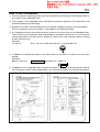
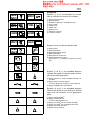
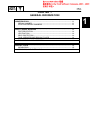
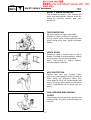
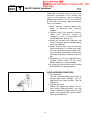
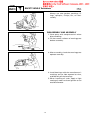
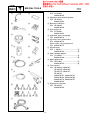
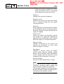
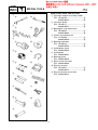
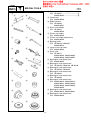
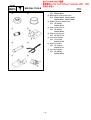
Z200Y
LZ200Y
SERVICE MANUAL
LIT186160203
LIT-18616-02-10
68F-28197-Z9-11
E
PREFACE
This manual has been prepared by the Yamaha Motor Company, Ltd. primarily for use by
Yamaha dealers and their trained mechanics when performing maintenance procedures and
repairs to Yamaha equipment. It has been written to suit the needs of persons who have a
basic understanding of the mechanical and electrical concepts and procedures inherent in the
work, for without such knowledge attempted repairs or service to the equipment could render
it unsafe or unfit for use.
Because the Yamaha Motor Company, Ltd. has a policy of continuously improving its products, models may differ in detail from the descriptions and illustrations given in this publication. Use only the latest edition of this manual. Authorized Yamaha dealers are notified
periodically of modifications and significant changes in specifications and procedures, and
these are incorporated in successive editions of this manual.
CAUTION
USE UNLEADED STRAIGHT GASOLINE ONLY
• Gasoline containing lead can cause performance
lose and engine damage.
• Do not use gasoline mixed with oil (premix).
• Use YAMALUBE 2 stroke outboard oil or another
2-stroke engine oil with a BIA-certified TC-W3 rate.
Z200Y, LZ200Y
SERVICE MANUAL
©1999 Yamaha Motor Co., Ltd.
1st Edition, September 1999
All rights reserved.
No part of this publication may be
reproduced or transmitted in any form or by
any means including photocopying and
recording without the written permission of
the copyright holder.
Such written permission must also be
obtained before any part of this publication
is stored in a retrieval system of any nature.
Printed in USA
LIT-18616-02-10
E
HOW TO USE THIS MANUAL
MANUAL FORMAT
All of the procedures in this manual are organized in a sequential, step-by-step format. The
information has been compiled to provide the mechanic with an easy to read, handy reference that contains comprehensive explanations of all disassembly, repair, assembly, and
check operations.
In this revised format, the condition of a faulty component will precede an arrow symbol and
the course of action required will follow the symbol, e.g.,
• Bearings
Pitting/scratches → Replace.
To assist you in finding your way through this manual, the section title and major heading is
given at the top of every page.
MODEL INDICATION
Multiple models are mentioned in this manual and their model indications are noted as follows.
Model name
Z200NETO
LZ200NETO
USA and
Canada name
Z200TR
LZ200TR
Indication
Z200NETO
LZ200NETO
ILLUSTRATIONS
The illustrations within this service manual represent all of the designated models.
CROSS REFERENCES
The cross references have been kept to a minimum. Cross references will direct you to the
appropriate section or chapter.
E
IMPORTANT INFORMATION
In this Service Manual particularly important information is distinguished in the following
ways.
The Safety Alert Symbol means ATTENTION! BECOME ALERT! YOUR SAFETY IS
INVOLVED!
WARNING
Failure to follow WARNING instructions could result in severe injury or death to the machine
operator, a bystander, or a person inspecting or repairing the outboard motor.
CAUTION:
A CAUTION indicates special precautions that must be taken to avoid damage to the outboard motor.
NOTE:
A NOTE provides key information to make procedures easier or clearer.
E
HOW TO USE THIS MANUAL
1 The main points regarding removing/installing and disassembling/assembling procedures
are shown in the exploded views.
2 The numbers in the exploded views indicate the required sequence of the procedure and
should be observed accordingly.
3 Symbols are used in the exploded views to indicate important aspects of the procedure.
A list of meanings for these symbols is provided on the following page.
4 It is important to refer to the job instruction charts at the same time as the exploded views.
These charts list the sequence that the procedures should be carried out in, as well as providing explanations on part names, quantities, dimensions and important points relating
to each relevant task.
Example:
O-ring size
39.5 × 2.5 mm: inside diameter (D) × ring diameter (d)
D
d
5 In addition to tightening torques, the dimensions of the bolts or screws are also mentioned.
Example:
Bolt or screw size
10 × 25 mm
: diameter (D) × length (L)
D
L
6 In addition to the exploded views and job instruction charts, this manual provides individual illustrations when further explanations are required to explain the relevant procedure.
E
1
SYMBOLS
2
GEN
INFO
Symbols 1 to 9 are designed as thumbtabs to indicate the content of a chapter.
SPEC
3
1
2
3
4
5
6
7
8
9
4
INSP
ADJ
FUEL
5
6
LOWR
POWR
7
General information
Specifications
Periodic inspections and adjustments
Fuel system
Power unit
Lower unit
Bracket unit
Electrical systems
Trouble analysis
8
BRKT
–
ELEC
9
Symbols 0 to E indicate specific data.
0
0
A
B
C
D
E
TRBL
ANLS
A
B
C
D
+
Special tool
Specified liquid
Specified engine speed
Specified torque
Specified measurement
Specified electrical value
[Resistance (Ω), Voltage (V), Electric current
(A)]
T.
R.
E
Symbol F to H in an exploded diagram
indicate the grade of lubricant and the location of the lubrication point.
F
E
G
H
M
A
I
J
4
GM
K
L
LT
LT
271
242
M
N
LT
572
SS
LT
F Apply Yamaha 2-stroke outboard motor oil
(TC-W3)
G Apply water resistant grease
(Yamaha grease A, Yamaha marine grease)
H Apply molybdenum disulfide oil
Symbols I to N in an exploded diagram
indicate the grade of the sealing or locking
agent and the location of the application
point.
I Apply Gasket Maker®
J Apply Yamabond #4
(Yamaha bond number 4)
K Apply LOCTITE® No. 271 (Red LOCTITE)
L Apply LOCTITE® No. 242 (Blue LOCTITE)
M Apply LOCTITE® No. 572
N Apply silicon sealant
E
CONTENTS
GENERAL INFORMATION
SPECIFICATIONS
PERIODIC INSPECTIONS AND
ADJUSTMENTS
FUEL SYSTEM
POWER UNIT
LOWER UNIT
BRACKET UNIT
GEN
INFO
SPEC
INSP
ADJ
FUEL
POWR
LOWR
BRKT
–
ELECTRICAL SYSTEMS
TROUBLE ANALYSIS
+
ELEC
TRBL
ANLS
1
2
3
4
5
6
7
8
9
GEN
INFO
E
CHAPTER 1
GENERAL INFORMATION
IDENTIFICATION ............................................................................................ 1-1
SERIAL NUMBER ..................................................................................... 1-1
STARTING SERIAL NUMBERS ............................................................... 1-1
SAFETY WHILE WORKING ............................................................................ 1-2
FIRE PREVENTION ................................................................................... 1-2
VENTILATION........................................................................................... 1-2
SELF-PROTECTION.................................................................................. 1-2
OILS, GREASES AND SEALING FLUIDS................................................ 1-2
GOOD WORKING PRACTICES ................................................................ 1-3
DISASSEMBLY AND ASSEMBLY ........................................................... 1-4
SPECIAL TOOLS ............................................................................................. 1-5
MEASURING ............................................................................................ 1-5
REMOVING AND INSTALLING ............................................................... 1-8
1
2
3
4
5
6
7
8
9
GEN
INFO
IDENTIFICATION
E
IDENTIFICATION
1
SERIAL NUMBER
The outboard motor’s serial number is
stamped on a label which is attached to the
port side of the clamp bracket.
NOTE:
If the serial number label is removed,
“VOID” marks will be appear on the label.
1
2
3
4
Model name
Approved model code
Transom height
Serial number
STARTING SERIAL NUMBERS
The starting serial number blocks are as follows:
Model name
Worldwide
USA
Canada
Approved
model
code
Z200NETO
Z200TR
Z200TR
6G6
X: 100101 -
—
6K1
X: 100101 -
LZ200NETO LZ200TR
1-1
Starting
serial
number
GEN
INFO
SAFETY WHILE WORKING
SAFETY WHILE WORKING
E
1
The procedures given in this manual are
those recommended by Yamaha to be followed by Yamaha dealers and their
mechanics.
FIRE PREVENTION
Gasoline (petrol) is highly flammable.
Petroleum vapor is explosive if ignited.
Do not smoke while handling gasoline and
keep it away from heat, sparks and open
flames.
VENTILATION
Petroleum vapor is heavier than air and is
deadly if inhaled in large quantities. Engine
exhaust gases are harmful to breathe.
When test-running an engine indoors,
maintain good ventilation.
SELF-PROTECTION
Protect your eyes with suitable safety
glasses or safety goggles, when grinding or
when doing any operation which may
cause particles to fly off. Protect hands and
feet by wearing safety gloves or protective
shoes if appropriate to the work you are
doing.
OILS, GREASES AND SEALING
FLUIDS
Use only genuine Yamaha oils, greases and
sealing fluids or those recommended by
Yamaha.
1-2
GEN
INFO
SAFETY WHILE WORKING
E
Under normal conditions of use, there
should be no hazards from the use of the
lubricants mentioned in this manual, but
safety is all-important, and by adopting
good safety practices, any risk is minimized.
A summary of the most important precautions is as follows:
1. While working, maintain good standards of personal and industrial
hygiene.
2. Clothing which has become contaminated with lubricants should be
changed as soon as practicable, and
laundered before further use.
3. Avoid skin contact with lubricants; do
not, for example, place a soiled wipingrag in your pocket.
4. Hands and any other part of the body
which have been in contact with lubricants or lubricant-contaminated clothing, should be thoroughly washed with
hot water and soap as soon as practicable.
5. To protect the skin, the application of a
suitable barrier cream to the hands
before working, is recommended.
6. A supply of clean lint-free cloths should
be available for wiping purposes.
GOOD WORKING PRACTICES
1. The right tools
Use the recommended special tools to
protect parts from damage. Use the
right tool in the right manner – do not
improvise.
2. Tightening torque
Follow the tightening torque instructions. When tightening bolts, nuts and
screws, tighten the large sizes first, and
tighten inner-positioned fixings before
outer-positioned ones.
1-3
GEN
INFO
SAFETY WHILE WORKING
E
3. Non-reusable items
Always use new gaskets, packings, Orings, split-pins, circlips, etc., on reassembly.
DISASSEMBLY AND ASSEMBLY
1. Clean parts with compressed air when
disassembling.
2. Oil the contact surfaces of moving parts
before assembly.
3. After assembly, check that moving parts
operate normally.
4. Install bearings with the manufacturer’s
markings on the side exposed to view,
and liberally oil the bearings.
5. When installing oil seals, apply a light
coating of water-resistant grease to the
outside diameter.
1-4
GEN
INFO
SPECIAL TOOLS
E
SPECIAL TOOLS
1
Using the correct special tools recommended by Yamaha, will aid the work and
enable accurate assembly and tune-up.
Improvising and using improper tools can
damage the equipment.
1
a
NOTE:
• For USA and Canada, use part numbers
that start with “J-”, “YB-”, “YM-”, “YS-”,
“YU-” or “YW-”.
• For worldwide, use part numbers that
start with “90890-”.
b
MEASURING
2
3
4
5
6
a
7
1 Tachometer
P/N. YU-08036-A ............................
90890-06760 ...........................
2 Fuel pressure gauge
P/N. YB-06766
90890-06786
3 Mity vac
P/N. YB-35956
90890-06756
4 Pressure tester
P/N. YB-35956
90890-06762
5 Digital caliper
P/N. 90890-06704
6 Pinion height gauge
P/N. YB-34432-7, YB-34432-11 ......
90890-06702 ...........................
7 Shimming gauge
P/N. YB-34446-1, YB-34446-3,
YB-34446-4, YB-34446-7,
YB-34446-8
8 Shimming gauge
P/N. YB-34468-1, YB-34468-2
9 Shimming plate
P/N. 90890-06701
0 Shift rod wrench
P/N. YB-06052 ................................
90890-06052 ...........................
b
8
9
0
a
b
1-5
a
b
a
b
a
b
GEN
INFO
SPECIAL TOOLS
A
B
C
D
E
F
G
H
I
a
a
a
E
A Magnetic base
P/N. YU-34481
90890-06705
B Magnetic base attaching plate
P/N. YB-07003
90890-07003
C Backlash indicator
P/N. YB-06265
90890-06706
D Dial gauge set
P/N. YU-03097
90890-01252
E Hydraulic pressure gauge
P/N. 90890-06776
F Up-relief valve attachment
P/N. 90890-06773
Down-relief valve attachment
P/N. 90890-06774
G Digital tester
P/N. J-39299 ...................................
90890-06752 ...........................
H Peak voltage adapter
P/N. YU-39991 ................................
90890-03169 ...........................
I Spark gap tester
P/N. YM-34487 ...............................
90890-06754 ...........................
J Test harness
P/N. YB-06443, YB-06767,
YB-06768, YB-06769,
YB-06779, YB-06787,
YB-06788
90890-06757, 90890-06767,
90890-06768, 90890-06769,
90890-06779, 90890-06787,
90890-06788
K Diagnostic indicator
P/N. YB-06765
90890-06765
b
b
b
J
K
1-6
a
b
a
b
a
b
GEN
INFO
SPECIAL TOOLS
E
L Diagnostic unit
Check the engine condition by using a
personal computer when it is connected
to the Electronic Control Unit (ECU).
Diagnosis:
Indicates the name of a failed part.
Diagnosis record:
Displays the name of the part whose diagnosis is detected, along with the engine
running total hours.
Static test:
Checks operation sound and ignition sparks
by activating the electric fuel pump, electric
oil pump, injector and spark plug while the
engine is stopped.
Dynamic test:
Checks the engine for operation through
any change in its speed by stopping the
operation of the spark plug on each cylinder
while the engine is in the neutral position.
Engine monitor:
Indicates information on the sensors and
switches by converting it to each value
while the engine is running.
Data logger:
Indicates in numeric values the engine
speed, throttle opening voltage, oxygen
density sensor voltage, water temperature
sensor voltage and fuel pressure sensor
voltage that occurred within 13 minutes.
ECU information:
Displays the ECU identification number.
NOTE:
To use any of these functions a personal
computer, connection cables, adapter and
communication software are required.
The personal computer should be compatible with Windows® 95/98, equipped with a
CD-ROM and the RS232C terminal.
1-7
GEN
INFO
SPECIAL TOOLS
E
REMOVING AND INSTALLING
1
2
a
b
a
b
a
b
a
b
a
b
1 Flywheel magnet assembly holder
P/N. YB-06139 ................................ a
90890-06522 ........................... b
2 Universal puller
P/N. YB-06117 ................................ a
90890-06521 ........................... b
3 Bearing/oil seal attachment
P/N. YB-06205 ................................ a
90890-06663 ........................... b
4 Piston ring compressor
P/N. YU-33294 ................................ a
90890-06530 ........................... b
5 Bearing separator
P/N. YB-06219 ................................ a
90890-06534 ........................... b
6 Guide plate stand
P/N. 90890-06538
7 Guide plate
P/N. 90890-06501
8 Bearing puller
P/N. 90890-06535
9 Small universal claws
P/N. 90890-06536
0 Ring nut wrench
P/N. YB-34447 ................................ a
90890-06512 ........................... b
A Ring nut wrench extension
P/N. 90890-06513
3
4
5
6
7
8
9
0
a
b
A
1-8
GEN
INFO
B
a
SPECIAL TOOLS
E
B Propeller shaft housing puller
P/N. YB-06207 ................................ a
90890-06502 ........................... b
C Center bolt
P/N. 90890-06504
D Slide hammer
P/N. YB-06096
90890-06531
E Drive shaft holder
P/N. YB-06201
90890-06520
F Pinion nut holder
P/N. 90890-06505
G Pinion nut holder attachment
P/N. 90890-06508
H Bearing puller
P/N. YB-06029, YB-06247
90890-06523
I Large universal claws
P/N. 90890-06532
J Driver rod
P/N. YB-06071
90890-06604, 90890-06605,
90890-06606, 90890-06652
K Bearing/oil seal depth plate
P/N. 90890-06603
L Bearing/oil seal attachment
P/N. YB-06194, YB-06196, YB-06246
M Bearing/oil seal attachment
P/N. YB-06195, YB-06258
N Bearing/oil seal attachment
P/N. YB-06200
O Bearing/oil seal attachment
P/N. YB-06336
P Bearing/oil seal attachment
P/N. 90890-06610, 90890-06612,
90890-06631, 90890-06633,
90890-06636, 90890-06653,
90890-06654
Q Bearing/oil seal attachment
P/N. 90890-06619, 90890-06622
R Bearing/oil seal attachment
P/N. 90890-06629
b
C
D
E
F
G
H
I
J
K
L
M
N
O
P
Q
R
1-9
GEN
INFO
SPECIAL TOOLS
S
T
U
V
W
X
Y
Z
E
S Bearing/oil seal attachment
P/N. 90890-06637
T Bearing/oil seal attachment
P/N. 90890-06659, 90890-06660,
90890-06661, 90890-06662
U Slide hammer attachment
P/N. YB-06335
90890-06514
V End screw wrench
P/N. YB-06548
90890-06548
W End screw wrench
P/N. YB-06175-1A
X Universal holder
P/N. YU-01235
90890-01235
Y Sheave holder
P/N. YS-1880-A
90890-01701
Z Universal puller
P/N. YB-06540
90890-06540
1-10
SPEC
E
CHAPTER 2
SPECIFICATIONS
GENERAL SPECIFICATIONS.......................................................................... 2-1
MAINTENANCE SPECIFICATIONS................................................................ 2-3
POWER UNIT............................................................................................ 2-3
LOWER UNIT............................................................................................ 2-5
ELECTRICAL ............................................................................................. 2-5
DIMENSIONS ........................................................................................... 2-9
TIGHTENING TORQUES .............................................................................. 2-11
SPECIFIED TORQUES ............................................................................ 2-11
GENERAL TORQUES ............................................................................. 2-13
1
2
3
4
5
6
7
8
9
SPEC
GENERAL SPECIFICATIONS
E
GENERAL SPECIFICATIONS
2
Model
Item
Worldwide
USA
Canada
DIMENSION
Overall length
Overall width
Overall height
(X)
Boat transom height
(X)
WEIGHT
(with aluminum propeller)
(X)
(with stainless steel propeller)
(X)
PERFORMANCE
Maximum output (ISO)
Full throttle operating range
Maximum fuel consumption
POWER UNIT
Type
Number of cylinders
Displacement
Bore × stroke
Compression ratio
Fuel system
Fuel injection system
Intake system
Induction system
Starting system
Ignition control system
Alternator output
Spark plugs (NGK)
Cooling system
Exhaust system
Lubrication system
Z200NETO
Z200TR
Z200TR
Unit
LZ200NETO
LZ200TR
—
mm (in)
mm (in)
792 (31.2)
554 (21.8)
mm (in)
1,782 (70.2)
mm (in)
635 (25.0)
kg (lb)
218 (480.6)
kg (lb)
222 (489.4)
kW (hp)
@ 5,000 r/min
r/min
L (US gal,
lmp gal)/hr
@ 5,500 r/min
147.1 (200)
cm3 (cu. in)
mm (in)
V-A
2-1
4,500 - 5,500
68 (18.0, 15.0)
2 stroke - V
6
2,596 (158.4)
90.0 × 68.0 (3.54 × 2.68)
Cylinders #1 - #4: 6.4
Cylinders #5 - #6: 6.1
Electronic fuel injection
Sequential injection
Reed valve
Loop charge
Electric
Microcomputer
12 - 45
BKR7ES-11
Water
Through propeller boss
Oil injection
SPEC
GENERAL SPECIFICATIONS
E
Model
Item
Worldwide
USA
Canada
FUEL AND OIL
Fuel type
Fuel rating
Engine oil type
Engine oil grade
Engine oil capacity
(engine oil tank)
(sub-oil tank)
Gear oil type
Gear oil total quantity
BRACKET
Trim angle
(at 12˚ boat transom)
Tilt-up angle
Steering angle
DRIVE UNIT
Gear shift positions
Gear ratio
Reduction gear type
Clutch type
Propeller shaft type
Propeller direction
(rear view)
Propeller mark
ELECTRICAL
Battery capacity
Minimum cold cranking
performance
Z200NETO
Z200TR
Z200TR
Unit
LZ200NETO
LZ200TR
—
Unleaded regular gasoline
86
91
2-stroke outboard engine oil
TC-W3
*PON
RON
L (US qt, lmp qt)
L (US qt, lmp qt)
cm3 (US oz,
lmp oz)
0.9 (0.95, 0.79)
10.5 (11.1, 9.2)
Hypoid gear oil SAE 90
980 (33.1, 34.5)
870 (29.4, 30.6)
Degree
–4 - 16
Degree
Degree
70
32 + 32
F-N-R
1.86 (26/14)
Spiral bevel gear
Dog clutch
Spline
Clockwise
Counterclockwise
M
Ah (kC)
A
ML
100 (360)
512
* PON: Pump Octane Number (Research octane + Motor octane)/2
RON: Research Octane Number
2-2
SPEC
MAINTENANCE SPECIFICATIONS
E
MAINTENANCE SPECIFICATIONS
2
POWER UNIT
Model
Item
Worldwide
USA
Canada
CYLINDER HEADS
Warpage limit
(lines indicate straightedge
position)
CYLINDERS
Bore size
Wear limit
Taper limit
Out-of-round limit
PISTONS
Piston diameter (D)
Measuring point (H)
Piston-to-cylinder clearance
<Limit>
Oversize piston diameter
1st
2nd
PISTON RINGS
Type
(B)
(T)
End gap (installed)
<Limit>
Side clearance
CRANKSHAFT
Runout limit
Z200NETO
Z200TR
Z200TR
Unit
LZ200NETO
LZ200TR
—
mm (in)
0.1 (0.004)
mm (in)
mm (in)
mm (in)
mm (in)
90.00 - 90.02 (3.543 - 3.544)
90.1 (3.55)
0.08 (0.003)
0.05 (0.002)
mm (in)
mm (in)
mm (in)
mm (in)
89.845 - 89.869 (3.5372 - 3.5381)
10 (0.4)
0.150 - 0.156 (0.0059 - 0.0061)
0.206 (0.0081)
mm (in)
mm (in)
90.11 (3.548)
90.36 (3.557)
mm (in)
mm (in)
mm (in)
mm (in)
mm (in)
Keystone
2.0 (0.079)
2.8 (0.110)
0.30 - 0.40 (0.012 - 0.016)
0.60 (0.024)
0.02 - 0.06 (0.001 - 0.002)
mm (in)
0.05 (0.002)
2-3
SPEC
MAINTENANCE SPECIFICATIONS
E
Model
Worldwide
USA
Canada
CONNECTING RODS
Small-end axial play
limit (F)
Big-end side
clearance (E)
OIL INJECTION PUMP
ID mark
Bleeding
REED VALVES
Reed valve stopper height a
Item
Z200NETO
Z200TR
Z200TR
Unit
LZ200NETO
LZ200TR
—
mm (in)
2.0 (0.08)
mm (in)
0.12 - 0.26 (0.005 - 0.010)
68F00
Screw type
mm (in)
9.0 ± 0.35 (0.35 ± 0.01)
Warpage limit b
THERMOSTATS
Opening temperature
Full-open temperature
mm (in)
0.2 (0.008)
˚C (˚F)
˚C (˚F)
48 - 52 (118 - 126)
60 (140)
Valve open lower limit
ENGINE SPEED
Idling speed
mm (in)
3 (0.12)
r/min
700 ± 30
2-4
SPEC
MAINTENANCE SPECIFICATIONS
E
LOWER UNIT
Model
Item
Worldwide
USA
Canada
Z200NETO
Z200TR
Z200TR
Unit
GEAR BACKLASH
Pinion - forward gear
mm (in)
Pinion - reverse gear
mm (in)
Pinion shims
Forward gear shims
Reverse gear shims
mm
mm
mm
LZ200NETO
LZ200TR
—
0.25 - 0.46
0.21 - 0.43
(0.010 - 0.018)
(0.008 - 0.017)
0.74 - 1.29
0.97 - 1.29
(0.029 - 0.051)
(0.038 - 0.051)
0.10, 0.12, 0.15, 0.18, 0.30, 0.40, 0.50
0.10, 0.12, 0.15, 0.18, 0.30, 0.40, 0.50
0.10, 0.12, 0.15, 0.18, 0.30, 0.40, 0.50
ELECTRICAL
Model
Item
Worldwide
USA
Canada
IGNITION SYSTEM
Ignition timing (#1)
Fuse 1
Fuse 2
Fuse 3
Control unit
(B/O, B/Y, B/L,
B/Br, B/G, B/W – R/Y)
Output peak voltage lower
limit
@ cranking 1
@ cranking 2
@ 1,500 r/min
@ 3,500 r/min
Pulser coil
(W/R, W/Y, W/G,
W/B, W/L, W/Br – B)
Output peak voltage lower
limit
@ cranking 1
@ cranking 2
@ 1,500 r/min
@ 3,500 r/min
Z200NETO
Z200TR
Z200TR
Unit
LZ200NETO
LZ200TR
—
Degree
V-A
V-A
V-A
ATDC 3 - BTDC 17
12-80
12-30
12-20
V
V
V
V
—
140
205
220
V
V
V
V
5.0
5.0
20
35
* Cranking 1: Open circuit voltage.
Cranking 2: Loaded circuit voltage.
2-5
SPEC
MAINTENANCE SPECIFICATIONS
E
Model
Worldwide
USA
Canada
IGNITION CONTROL SYSTEM
Crank position sensor
(G/L)
Crank-position-sensor-toflywheel gap
Output peak voltage lower
limit
@ cranking 1
@ cranking 2
@ 1,500 r/min
@ 3,500 r/min
Engine cooling water
temperature sensor
Resistance
(B/Y – B/Y)
@ 5˚C (41˚F)
@ 20˚C (68˚F)
@ 100˚C (212˚F)
Throttle position sensor
Input voltage
(O – R)
Output voltage
(P – O)
Thermo switch
(P – B)
OFF → ON
ON → OFF
FUEL CONTROL SYSTEM
Oxygen density sensor
Heater resistance (R/W – B)
Output voltage
(Gy – B/W)
Atmospheric pressure sensor
Output voltage (at 101.32 kPa)
(P – B)
Intake air temperature sensor
Resistance
(B/Y – B/Y)
Injector driver
(O/R – Pu/R, O/B – Pu/B,
O/Y – Pu/Y, O/G – Pu/G,
O/L – Pu/L, O/W – Pu/W)
Output peak voltage lower
limit
@ cranking 1
@ cranking 2
@ 1,500 r/min
@ 3,500 r/min
Item
Z200NETO
Z200TR
Z200TR
Unit
LZ200NETO
LZ200TR
—
mm (in)
1.0 ± 0.5 (0.04 ± 0.02)
V
V
V
V
4.5
4.0
13
20
kΩ
kΩ
kΩ
128
54 - 69
3.02 - 3.48
V
V
4.75 - 5.25
0.50 ± 0.02
˚C (˚F)
˚C (˚F)
84 - 90 (183 - 194)
60 - 74 (140 - 165)
Ω
V
2 - 100
0.0 - 1.0
V
3.2 - 4.6
kΩ
1.5 - 4.0
V
V
V
V
65
60
65
65
* Cranking 1: Open circuit voltage.
Cranking 2: Loaded circuit voltage.
2-6
SPEC
MAINTENANCE SPECIFICATIONS
E
Model
Worldwide
USA
Canada
Fuel pressure sensor
Output voltage
(P – B)
Water detection switch
Float position a “ON”
Item
Z200NETO
Z200TR
Z200TR
Unit
LZ200NETO
LZ200TR
—
V
2.8 - 3.2
mm (in)
47
kW
Second
Sliding gear
1.4
30
mm (in)
mm (in)
15.5 (0.61)
9.5 (0.37)
mm (in)
mm (in)
29.0 (1.14)
28.0 (1.10)
mm (in)
mm (in)
0.5 - 0.8 (0.02 - 0.03)
0.2 (0.01)
V
V
V
V
—
7.5
12.7
12.7
V
V
V
V
7.5
8.0
12
12
a
STARTER MOTOR
Type
Output
Cranking time limit
Brushes
Standard length
Wear limit
Commutator
Standard diameter
Wear limit
Mica
Standard undercut
Wear limit
CHARGING SYSTEM
Rectifier/regulator
(R – B)
Output peak voltage lower
limit
@ cranking 1
@ cranking 2
@ 1,500 r/min
@ 3,500 r/min
Lighting coil
(G – G)
Output peak voltage lower
limit
@ cranking 1
@ cranking 2
@ 1,500 r/min
@ 3,500 r/min
* Cranking 1: Open circuit voltage.
Cranking 2: Loaded circuit voltage.
2-7
SPEC
MAINTENANCE SPECIFICATIONS
E
Model
Worldwide
USA
Canada
OIL FEED PUMP CONTROL
SYSTEM
Oil level sensor
(engine oil tank)
Float position a
“OFF”
Float position b
“ON”
Float position c “ON”
Oil level switch (sub-oil tank)
Float position d “ON”
POWER TRIM AND TILT SYSTEM
Trim sensor
Setting resistance
Resistance
(P – B)
Resistance
(O – B)
POWER TRIM AND TILT MOTOR
Fluid type
Brushes
Standard length
Wear limit
Commutator
Standard diameter
Wear limit
Mica
Standard undercut
Wear limit
Item
Z200NETO
Z200TR
Z200TR
Unit
LZ200NETO
LZ200TR
—
mm (in)
3 - 6 (0.12 - 0.24)
mm (in)
33 - 36 (1.30 - 1.42)
mm (in)
53 - 56 (2.09 - 2.20)
mm (in)
150 - 153 (5.91 - 6.02)
Ω
Ω
Ω
80 ± 12
582 - 873
800 - 1,200
ATF Dexron II
mm (in)
mm (in)
9.8 (0.39)
4.8 (0.19)
mm (in)
mm (in)
22.0 (0.87)
21.0 (0.83)
mm (in)
mm (in)
1.35 (0.05)
0.85 (0.03)
2-8
SPEC
MAINTENANCE SPECIFICATIONS
E
DIMENSIONS
L7
L6
L2
H9
L1
W5
H2
W1
H7
H4
H1
H6
H3
L5
L4
Symbol
Worldwide
USA
Canada
L1
L2
L4
L5
L6
L7
H1
H2
H3
H4
H6
H7
H9
W1
W5
Models
Unit
mm (in)
mm (in)
mm (in)
mm (in)
mm (in)
mm (in)
mm (in)
mm (in)
mm (in)
mm (in)
mm (in)
mm (in)
mm (in)
mm (in)
mm (in)
2-9
Z200NETO
Z200TR
Z200TR
LZ200NETO
LZ200TR
—
613 (24.1)
180 (7.1)
646 (25.4)
69 (2.7)
1,150 (45.3)
574 (22.6)
1,074 (42.3)
708 (27.9)
211 (8.3)
643 (25.3)
850 (33.4)
308 (12.1)
835 (32.9)
277 (10.9)
396 (15.6)
SPEC
MAINTENANCE SPECIFICATIONS
Symbol
Worldwide
USA
Canada
B1
B2
B3
B4
B5
B6
B9
C3
D1
D2
Unit
mm (in)
mm (in)
mm (in)
mm (in)
mm (in)
mm (in)
mm (in)
mm (in)
mm (in)
mm (in)
2-10
E
Models
Z200NETO
LZ200NETO
Z200TR
LZ200TR
Z200TR
—
125.4 (4.9)
254 (10.0)
163.5 (6.4)
50.8 (2.0)
180 (7.1)
367 (14.4)
18.5 (0.7)
82 (3.2)
13 (0.5)
55.5 (2.2)
SPEC
TIGHTENING TORQUES
E
TIGHTENING TORQUES
2
SPECIFIED TORQUES
Part to be tightened
POWER UNIT
Intake silencer
Electric oil pump
Fuel injection unit
Atmospheric pressure sensor
Electric oil pump bracket
Throttle position sensor
Intake air temperature sensor
Drive belt tensioner
Mechanical fuel pump
Fuel rail
Fuel injector cap
Fuel filter nut holder
Oil pump
Emergency switch
Flywheel magnet assembly
Negative battery lead
Positive battery lead
Apron
Power unit mount
Starter relay holder
Oxygen density sensor cover
Oxygen density sensor bracket
Oxygen density sensor
Reed valve assembly
Reed valve
Reed valve stopper
Shift position switch
Spark plug
1st
2nd
1st
Cylinder head cover
2nd
Engine cooling water temperature
sensor
1st
Cylinder head
2nd
1st
Cooling water pressure
control valve cover
2nd
1st
Exhaust port outer cover
2nd
Thermostat cover
Thread size
M6
M6
M6
M6
M6
M5
M12
M10
M8
M8
M8
M6
M6
—
M20
M8
M8
M6
M8
M5
M6
M6
M18
M6
M5
M3
M4
M14
M6
M6
—
M8
M6
M6
2-11
Nm
Tightening torques
m•kgf
ft•lb
3
8
10
4
8
4
8
40
23
23
26
8
7
4
190
9
9
8
21
3
9
14
49
10
3
1
3
25
5
11
5
11
0.3
0.8
1.0
0.4
0.8
0.4
0.8
4.0
2.3
2.3
2.6
0.8
0.7
0.4
19
0.9
0.9
0.8
2.1
0.3
0.9
1.4
4.9
1.0
0.3
0.1
0.3
2.5
0.5
1.1
0.5
1.1
2.2
5.8
7.2
2.9
5.8
2.9
5.8
29
17
17
19
5.8
5.1
2.9
137
6.5
6.5
5.8
15
2.2
6.5
10
35
7.2
2.2
0.7
2.2
18
3.6
8.0
3.6
8.0
15
1.5
11
15
30
4
8
4
8
1.5
3.0
0.4
0.8
0.4
0.8
11
22
2.9
5.8
2.9
5.8
SPEC
TIGHTENING TORQUES
Part to be tightened
Crankcase
Connecting rod
19
37
Tightening torques
m•kgf
1.0
1.8
2.0
4.0
1.9
3.7
*
1.9
3.7
M18
M10
—
M22
—
—
55
40
145
95
7
7
5.5
4.0
14.5
9.5
0.7
0.7
40
29
105
68
5.1
5.1
M5
—
M12
M14
M8
M8
M8
M8
M22
M6
—
5
24
53
73
21
18
18
18
15
2
37
0.5
2.4
5.3
7.3
2.1
1.8
1.8
1.8
1.5
0.2
3.7
3.6
17
38
53
15
13
13
13
11
1.4
27
—
1/4”
1/4”
—
—
5/16”
—
—
8
5
5
4
130
9
6
80
0.8
0.5
0.5
0.4
13
0.9
0.6
8.0
5.8
3.6
3.6
2.9
94
6.5
4.3
52
Thread size
1st
2nd
1st
2nd
1st
2nd
3rd
4th
5th
LOWER UNIT
Propeller
Lower unit
Ring nut
Pinion nut
Gear oil drain screw
Gear oil level check screw
BRACKET UNIT
Flushing hose
Shift rod detent mechanism screw
Upper mount
Lower mount
Exhaust manifold assembly
Muffler
Exhaust manifold
Lower exhaust manifold guide
Clamp bracket
Trim sensor stopper
Trim stopper
POWER TRIM AND TILT UNIT
Power trim and tilt reservoir cap
Power trim and tilt reservoir
Power trim and tilt motor
Manual valve
Tilt ram end screw
Gear pump unit
Gear pump
Trim ram end screw
E
M8
M10
Nm
10
18
20
40
19
37
M8
*: Loosen
2-12
ft•lb
7.2
13
14
29
14
27
14
27
SPEC
TIGHTENING TORQUES
Nut (A)
Bolt (B)
8 mm
10 mm
12 mm
14 mm
17 mm
M5
M6
M8
M10
M12
E
GENERAL TORQUES
General torque
specifications
Nm m•kgf ft•lb
5
0.5
3.6
8
0.8
5.8
18
1.8
13
36
3.6
25
43
4.3
31
This chart specifies tightening torques for
standard fasteners with a standard ISO
thread pitch. Tightening torque specifications for special components or assemblies
are provided in applicable sections of this
manual. To avoid warpage, tighten multifastener assemblies in a crisscross fashion
and progressive stages until the specified
tightening torque is reached. Unless otherwise specified, tightening torque specifications
require
clean,
dry
threads.
Components should be at room temperature.
2-13
INSP
ADJ
E
CHAPTER 3
PERIODIC INSPECTIONS AND ADJUSTMENTS
MAINTENANCE INTERVAL CHART .............................................................. 3-1
TOP COWLING ............................................................................................... 3-3
CHECKING THE TOP COWLING FIT ....................................................... 3-3
FUEL SYSTEM ................................................................................................ 3-3
CHECKING THE FUEL LINE ..................................................................... 3-3
CHECKING THE FUEL FILTER ................................................................. 3-4
MEASURING THE FUEL PRESSURE
(MEDIUM-PRESSURE FUEL LINE)......................................................... 3-5
CHECKING THE FUEL PRESSURE (MECHANICAL FUEL PUMP) ......... 3-5
CHECKING THE MECHANICAL FUEL PUMP OIL LEVEL....................... 3-6
CHANGING THE MECHANICAL FUEL PUMP OIL ................................. 3-6
CONTROL SYSTEM........................................................................................ 3-7
SYNCHRONIZING THE THROTTLE VALVES.......................................... 3-7
ADJUSTING THE THROTTLE POSITION SENSOR................................ 3-8
ADJUSTING THE ENGINE IDLING SPEED............................................. 3-9
ADJUSTING THE REMOTE CONTROL SHIFT CABLE ......................... 3-10
ADJUSTING THE REMOTE CONTROL THROTTLE CABLE................. 3-10
CHECKING THE DRIVE BELT................................................................. 3-11
ADJUSTING THE CRANK POSITION SENSOR.................................... 3-12
COOLING SYSTEM ...................................................................................... 3-12
CHECKING THE COOLING WATER DISCHARGE ................................ 3-12
OIL INJECTION SYSTEM ............................................................................. 3-12
CHECKING THE OIL STRAINER ............................................................ 3-12
SYNCHRONIZING THE OIL PUMP........................................................ 3-13
AIR BLEEDING THE OIL INJECTION SYSTEM..................................... 3-14
CHECKING THE ELECTRIC OIL PUMP.................................................. 3-14
POWER TRIM AND TILT SYSTEM .............................................................. 3-15
CHECKING THE POWER TRIM AND TILT FLUID LEVEL ..................... 3-15
ADJUSTING THE TRIM SENSOR CAM ................................................ 3-16
LOWER UNIT ................................................................................................ 3-16
CHECKING THE GEAR OIL LEVEL ........................................................ 3-16
CHANGING AND CHECKING THE GEAR OIL ...................................... 3-17
CHECKING THE LOWER UNIT (FOR AIR LEAKS) ................................ 3-18
INSP
ADJ
GENERAL ...................................................................................................... 3-18
CHECKING THE ANODES...................................................................... 3-18
CHECKING THE BATTERY..................................................................... 3-19
CHECKING THE SPARK PLUGS............................................................ 3-20
LUBRICATION POINTS.......................................................................... 3-22
E
1
2
3
4
5
6
7
8
9
INSP
ADJ
MAINTENANCE INTERVAL CHART
E
MAINTENANCE INTERVAL CHART
3
Use the following chart as a guide to general maintenance intervals.
Dependant on operating conditions, adjust the maintenance intervals accordingly.
Initial
Item
Remarks
10 hours 50 hours 100 hours 200 hours
(Break-in) (3 months) (6 months) (1 year)
TOP COWLING
Top cowling fit
Check
FUEL SYSTEM
Fuel line
Check
Fuel filter
Clean/check
Mechanical fuel pump oil Change
Fuel tank
Clean
POWER UNIT
Water leakage
Check
Motor exterior
Check
Exhaust leakage
Check
(*1)
Cooling water passage
Clean
CONTROL SYSTEM
Throttle valve
Check/adjust
synchronization
Engine idling speed
Check/adjust
Throttle position sensor
Check/adjust
Remote control shift cable Check/adjust
Remote control throttle
Check/adjust
cable
Drive belt(*2)
Check/adjust
OIL INJECTION SYSTEM
Oil tank water drain
Clean
Oil pump lever
Check/adjust
POWER TRIM AND TILT UNIT
Power trim and tilt fluid
Check
LOWER UNIT
Gear oil
Change
Lower unit leakage
Check
Propeller and cotter pin
Check/replace
(*1)
(*2)
Every
Refer to
page
3-3
3-3
3-4
3-6
—
—
—
—
—
3-7
3-9
3-8
3-10
3-10
3-11
—
3-13
3-15
3-16
3-18
6-3, 6-30
When operating in salt water, turbid or muddy water, the engine should be flushed with
clean water after each use.
Be sure to replace the drive belt after every 1,000 hours (5 years) of operation.
3-1