1
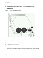
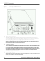
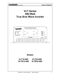
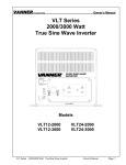
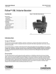
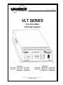
Owner’s Manual
VLT SERIES
True Sine Wave
AC Power Inverter
60Hz Models
VLT12-600
VLT24-600
VLT12-1000
VLT24-1000
VLT48-1000
50Hz Models
VLT12-1500
VLT24-1500
VLT48-1500
VLTE12-600
VLTE24-600
VLTE12-1000 VLTE12-1500
VLTE24-1000 VLTE24-1500
VLTE48-1000 VLTE48-1500
Owner’s Manual D910106 Rev. B
Rev. May 24, 2007
VANNER
Incorporated
Vanner Incorporated
4282 Reynolds Drive
Hilliard, OH 43026
800-AC POWER (800-227-6937)
Tel: 614-771-2718
Fax: 614-771-4904
www.vanner.com
e-mail: [email protected]
© Copyright 2007, Vanner Inc.
2
VLT Series True Sine Wave Inverter - Owner’s Manual
VANNER
Incorporated
TABLE OF CONTENTS
Section 1:
Section 2:
Section 3:
Section 4:
Section 5:
Section 6:
Section 7:
Introduction ................................................................................................................................. 4
Model Listing ............................................................................................................................... 4
Specifications and Features ........................................................................................................ 5
Standard Features ...................................................................................................................... 6
Definitions ................................................................................................................................... 6
Safety Instructions ...................................................................................................................... 7
Readme ...................................................................................................................................... 7
General Precautions ................................................................................................................... 7
Explosive Gas Precautions ......................................................................................................... 8
Battery Precautions ..................................................................................................................... 8
Component Identification and Description of Operation .............................................................. 9
Cooling Fans ............................................................................................................................... 9
Battery Voltage Indicator ........................................................................................................... 10
Load Watt Indicator ................................................................................................................... 10
Over Voltage Indicator .............................................................................................................. 10
Under Voltage Indicator ............................................................................................................ 11
Over Temperature Indicator ...................................................................................................... 11
Overload Indicator ..................................................................................................................... 11
ON/OFF Switch ......................................................................................................................... 11
Inverter Indicator Light .............................................................................................................. 11
GFCI Duplex Receptacle .......................................................................................................... 11
Installation and Setup ................................................................................................................ 12
Unpacking the Inverter .............................................................................................................. 12
Inverter Installation Considerations ........................................................................................... 12
DC Wiring Considerations ......................................................................................................... 12
DC Wiring Installation Procedure .............................................................................................. 13
AC Output Wiring Installation Procedure ................................................................................... 14
Start-up and Test Procedure ..................................................................................................... 14
Inverter Start-up and Testing ..................................................................................................... 14
Preventative Maintenance and Troubleshooting Procedures .................................................... 15
Preliminary Checks ................................................................................................................... 15
Problem Symptoms and Troubleshooting Checks ..................................................................... 16
Appendix ................................................................................................................................... 17
GFCI Test Record ...................................................................................................................... 19
LIST OF FIGURES
Figure 1
Figure 2
Figure 3
Figure 4
Inverter Specifications ................................................................................................................. 5
Inverter Top, Right Side & Rear View .......................................................................................... 9
Inverter Top, Left Side & Front View ......................................................................................... 10
GFCI Test Record ..................................................................................................................... 19
VLT Series True Sine Wave Inverter - Owner’s Manual
3
VANNER
Incorporated
1. INTRODUCTION
Thank you for purchasing a Vanner VLT SERIES Inverter. We are confident that you will be satisfied with its
performance and its many features. With proper installation and care, you can look forward to years of service
from this high performance product.
The VLT SERIES is a family of dependable inverters designed to meet common service requirements of the
consumer, commercial and industrial markets. All models of the VLT SERIES produce true sine wave AC
output power.
This document will describe the operation, technical specifications and installation procedures of the various
models and accessories offered in this product family. We suggest that you familiarize yourself with the model
numbers of the inverter and optional accessories you have purchased before proceeding with this manual. If
you require additional information please contact your dealer, or contact us directly at
1-800-227-6937 (800 AC POWER) or www.vanner.com.
WARNING:
Before you install and use your VLT SERIES Inverter be sure to read and save these
safety instructions.
Model Listing
The VLT SERIES product line is designed to meet the requirements of a variety of applications.
NOTICE:
Most models of the VLT SERIES use the same front panel and therefore look identical. To
identify the model number of your particular unit it is necessary to refer to the Specification Label
located on the right side of the unit or to the Identification Label located on the front.
Please note your model and serial number here for future reference.
Model No.____________________ Serial No.___________________ Date of Installation ______________
4
VLT Series True Sine Wave Inverter - Owner’s Manual
VANNER
Incorporated
2. SPECIFICATIONS & FEATURES
Specifications
Figure 1
Inverter Specifications
Surge (3S) A
16
3.33
24
12
24
12
24
VLTE 48-1500
VLTE 24-1500
16.7
8
48
VLTE 12-1500
VLT 48-1500
VLT 24-1500
VLT 12-1500
VLTE 48-1000
VLTE 24-1000
1500W
1000W
6.67
12
VLTE 12-1000
VLT 48-1000
VLT 24-1000
VLT 12-1000
VLTE 24-600
600W
Continuous Output
Input Voltage
VLTE 12-600
VLT 24-600
VLT 12-600
MODEL
VANNER VLT & VLTE INVERTER SPECIFICATIONS
12
48
24
12
24
8.3
48
12
24
48
Output Voltage
120V +/- 3% 230V +/- 3%
120V +/- 3%
230V +/- 3%
120V +/- 3%
230V +/- 3%
Output Frequency
60Hz +/- .05% 50Hz +/-.05%
60Hz +/-.05%
50Hz +/-.05%
60Hz +/-.05%
50Hz +/-.05%
25
12.5
Peak Current A
Efficiency FL - %
5
10
88
No Load Current
90
92
94
83
< 1 amp
87
88
83
87
25
88
12.5
83
87
88
83
87
88
< 1.0W In Power Saving Mode
Output Waveform
Pure Sine Wave < 3% THD
120V RMS -10% / +4%
O/P Regulation
Low Battery Volts
10.7
21.5
10.7
21.5
10
20
40
10
20
40
10
20
40
10
20
40
High Battery Volts
15
30
15
30
16
32
64
16
32
64
16
32
64
16
32
64
Standby Recovery
5 Seconds
Operating Temp.
32 to 122F (0 to 50C)
Storage Temp.
Dimensions
Weight
-22 to 158F (-30 to 70C)
3”H x 7.25”W x 11”D
6.6 lbs.
4.13”H x 10.83”W x 15.35”D
15.1 lbs.
15.4 lbs.
LED Status
Low Battery Shutdown, Over Temperature Shutdown, Overload, Inverter ON/OFF Indicator
Protection
Overload, Short Circuit, Reverse Polarity (fuse), Over/Under Input Voltage, Over Temp.
Mounting
Inverter may be mounted in any orientation
VLT Series True Sine Wave Inverter - Owner’s Manual
5
VANNER
Incorporated
Standard Features
1.
2.
3.
4.
5.
6.
7.
True sine wave 120 volt AC output.
Resilient electronic protection designed to handle output short circuits and output overloads.
Load Demand Feature to conserve DC power under no load conditions. (Not on 600-watt models.)
15 amp GFCI Duplex Receptacle.
Automatic shutoff for low or high battery voltage, overload or over temperature with indicator LEDs.
Remote control circuit. (Not present on 600-watt models.)
Indicator lights for Low Battery Shutoff, Over Temperature Shutoff, Overload and Inverter ON/OFF/Load
Demand status.
8. Thermostatically controlled cooling intake fan.
Definitions
Load Demand Feature and Load Demand Mode:
The Load Demand Feature is an energy conserving feature which allows the inverter to enter the ‘Load Demand
Mode’ whenever the inverter is ON and the AC load has been less than 10 watts for approximately 10 seconds.
While in the ‘Load Demand Mode’ the inverter does not produce 120 volts AC but instead produces pulses of
voltage which the inverter uses to look for a load. When a load greater than 10 watts is sensed, the inverter will
turn fully ON to produce 120 Volts AC. The ‘Load Demand Mode’ is often also described as ‘stand-by mode’ or
‘sleep mode’. While in the ‘Load Demand Mode’ 12-volt models consume approximately 0.1 amps of DC and 24volt models consume approximately 0.05 amps of DC.
Load Demand can be turned off by setting factory setup DIP switch #4 to the up position.
6
VLT Series True Sine Wave Inverter - Owner’s Manual
VANNER
Incorporated
3. SAFETY INSTRUCTIONS
README
WARNING: Before you install and use your VLT SERIES AC Power Inverter, be sure
to read and save these safety instructions.
This manual contains important safety and operating instructions for the Vanner Power Group VLT SERIES
Power Inverter as prescribed by Underwriters Laboratories (UL). The VLT SERIES inverters are designed to
be compliant with UL 458, Power Converters/Inverters and Power Converter/Inverter Systems.
NOTICE:
The output waveform of the VLT SERIES inverter is sinusoidal. Total harmonic distortion is
less than three percent.
CAUTION:
Read owners manual BEFORE wiring or powering up.
CAUTION:
Not intended for DC input directly from a solar array. Batteries must be used.
CAUTION:
DO NOT cover or obstruct ventilation openings. DO NOT mount in a zero-clearance compartment. Overheating may result.
WARNING:
Under high ambient temperature / high-power-output conditions some parts of the inverter
may become hot enough to cause burns. The unit should be installed so that it is not to be
contacted by personnel.
WARNING:
This equipment employs components that tend to produce arcs and sparks. To prevent fire or
explosion, DO NOT install in confined areas or compartments that contain batteries or flammable materials.
WARNING:
Improper use of this product may result in risk of electrical shock. Both AC and DC voltage
sources are terminated inside this equipment.
Use only the ground fault circuit interrupter (GFCI) receptacle(s) or circuit breaker(s) specified
in the installation and operating instructions. Other types may fail to operate properly when
connected to this equipment.
DANGER:
Battery connections are for disconnect only, NOT for current interruption.
General Precautions
1. Do not expose the inverter to direct water spray or snow.
2. To reduce the risk of a fire hazard, do not cover or obstruct the ventilation openings.
3. Do not install the inverter in a zero clearance compartment. This may result in overheating or diminished performance.
4. To avoid the risk of fire, electrical shock, or injury to persons, do not use attachments not recommended or sold by Vanner Inc.
5. Vanner recommends that all AC and DC electrical wiring be performed by a licensed electrician or a
qualified technician to ensure compliance with all applicable national and local wiring regulations.
6. To avoid a risk of fire and/or electrical shock, always verify wiring connections are in good electrical
condition. All external conductors must use proper wire size to avoid dangerous overheating or
diminished performance.
VLT Series True Sine Wave Inverter - Owner’s Manual
7
VANNER
Incorporated
7. If the inverter has been dropped or damaged in any way, do not operate the inverter until it has been
verified to be safe by a qualified technician.
8. To reduce the risk of electrical shock, always disconnect the AC and DC connections to the inverter
before attempting any maintenance. Simply turning the inverter off does not prevent electrical shock.
9. The inverter must be properly grounded in accordance with local and national codes and ordinances
before operation. For most installations, the negative (ground) conductor should be bonded to the
grounding system at one and only one point in the system.
10. For optimum inverter performance, battery temperature should be above 32 degrees Fahrenheit.
11. Do not disassemble the inverter. See the service section of this manual for instructions on obtaining
service. Attempting to service the inverter yourself may result in a risk of electrical shock, fire and/or
loss of warranty.
Explosive Gas Precautions
1. This equipment contains components, which tend to produce arcs or sparks. To prevent fire or explosion, do not install in compartments containing batteries or flammable materials, or in locations that
require ignition protected equipment. This includes any space containing gasoline-powered machinery,
fuel tanks, or joints, fittings, or other connections between components of the fuel system.
2. To reduce the risk of battery explosion, follow these instructions, the battery manufacturer instructions,
and the instructions of the manufacturer of the equipment in which the battery is installed. Working
near a lead-acid battery is dangerous. Batteries generate explosive gases during normal battery
operation.
Battery Precautions
1. Always have someone within range of your voice to come to your aid when you work near a lead-acid
battery.
2. Have close access to plenty of fresh water and soap in case battery acid contacts skin, clothing, or
eyes.
3. Always wear complete eye protection and clothing protection. Avoid touching eyes while working near
batteries.
4. If battery acid contacts skin or clothing, wash immediately with soap and water. If acid enters eye,
immediately flood eye with running cold water for at least 20 minutes. Get medical attention immediately.
5. NEVER smoke or allow a spark or flame near a battery. Gases produced by batteries are explosive.
6. Be careful when working with metal tools around batteries. Potentials exist for sparks or short-circuit
of the battery or other electrical part which could cause an explosion.
8
VLT Series True Sine Wave Inverter - Owner’s Manual
VANNER
Incorporated
4. COMPONENT IDENTIFICATION and DESCRIPTION OF
OPERATION
Figure 2
Inverter Top, Right Side & Rear View
(1)
Rear entry for negative DC input cable
(2)
Rear entry for positive DC input cable
(3)
Rear entry for Remote Control RS 232 Connection
(4)
Chassis Ground Bonding Lug
(5)
Cooling Fans
Draw air in through intake vents on the top, sides and bottom of inverter and exhaust it out the back for the
purpose of cooling the unit. Fans will not continue running when the inverter goes to sleep.
VLT Series True Sine Wave Inverter - Owner’s Manual
9
VANNER
Incorporated
Figure 3
Inverter Top, Left Side & Front View
(6) Battery Voltage Indicator
The battery voltage bar graph indicates the voltage at the input terminals of the inverter. At low input
current, this voltage is very close to the battery voltage. At high input current, this voltage will be lower
than the battery voltage because of the voltage drop across the cable and connections.
Ideally, the voltage should remain in the green areas of the bar graph. If the voltage indicator light is in
the red areas of the graph, the inverter may shut itself OFF.
(7)
Load Watt Indicator
The AC load watt bar graph indicates the power drawn from the inverter. It will indicate wattage by loads.
For long term operation, indicated wattage should be in the green and orange area of the graph. Short
term operation is possible with wattage in the red area. If total wattage allowed is reached, the entire bar
graph will flash as a warning but the load will continue to be supported. If total wattage allowed is
exceeded, the inverter will shut itself OFF.
(8)
Over Voltage Indicator
Indicates that the inverter has shut itself OFF due to input voltage over 16.5 volts (33.0 volts for 24 volt
models; 15.0 volts and 30.0 volts for 600 watt models).
10
VLT Series True Sine Wave Inverter - Owner’s Manual
VANNER
(9)
Incorporated
Under Voltage Indicator
Indicates that the inverter has shut itself OFF due to input voltage under 10.0 volts (20.0 volts for 24 volt
models).
(10) Over Temperature Indicator
Indicates that the inverter has shut itself OFF due to overheating. The inverter may overheat if operated
at power levels above its rating, or if installed in a location that does not allow for proper ventilation. The
inverter will restart automatically after a cooling period.
(11) Overload Indicator
The inverter has shut OFF because its output has been short circuited or drastically overloaded. Turn
the ON/OFF switch to the OFF position, correct the fault condition, and turn the inverter back ON.
(12) ON/OFF Switch
(and RESET Switch)
The ON/OFF Switch is a two-position rocker switch used to turn the inverter ON/OFF and is used as a
RESET Switch. When the inverter has automatically shut itself OFF due to a fault, the inverter must be
RESET by turning the ON/OFF Switch OFF or by turning a remote switch OFF. (If an automatic shutdown has occurred due to a fault, one of the fault indicator lights will be displayed until the inverter is
RESET.
(13) Inverter Indicator Light
Light Display
Description
Green Light is OFF
Inverter is OFF
Solid Green
Inverter is ON and is producing AC power
Blinking Green
Inverter is in Load Demand Mode
(14) Factory set-up dip switch (Not present on 600-watt models.)
(15) Air Intake Vents
(16) Mounting Base Rails ( 2 )
(17) GFCI Duplex Receptacle
VLT Series True Sine Wave Inverter - Owner’s Manual
11
VANNER
Incorporated
5. INSTALLATION and START UP
Unpacking the Inverter
1. Inspect the shipping container and equipment for loose or damaged parts. If any damage is found,
immediately notify the freight carrier.
Inverter Installation Considerations
1. Mounting: Locate a secure, dry, flat horizontal or vertical surface large enough to mount the inverter.
The location should be as close to the battery as possible, usually within six feet, but not in the same
compartment and should provide adequate ventilation while the inverter is operating. The location
must be clean, dry and free from road spray, dripping water or other moisture contamination.
2. Cooling Fan Clearance: The mounting location must allow unobstructed airflow for cooling. Allow a
minimum clearance of 1½ inches (40 mm) on the left, right and back sides of the inverter. The Cooling
Fan is a thermostatically controlled intake fan. Air is drawn into the inverter from the front and side
vents and exhausted through the fans. Obstruction of the fan intake or the exhaust vents will diminish
the inverter output capacity due to overheating.
DC Wiring Considerations
12
1.
A DC FUSE IS REQUIRED to properly protect the inverter in case the battery cables are connected
backward (reverse polarity).
2.
The wiring of your inverter installation should conform to the National Electric Code (NEC) and any
other state or local codes in effect at the time of installation. These codes have been written for your
protection and their requirements should be followed. Article 551 of the NEC requires any DC cable
from a battery, which measures longer than 18 inches along its length, be protected by a fuse.
3.
BE AWARE, as a large number of capacitors become charged upon completion of the DC circuit,
THERE WILL BE A LARGE SPARK when the last battery connection is made. The spark is normal
and will occur every time the batteries are connected. It is advisable to make the last DC connection
at the input fuse, not at the battery, to reduce the risk of battery explosion.
4.
Route the AC output wiring and DC power wiring with as much physical separation as possible from
low voltage wiring such as audio and video signal wires.
5.
Route the DC positive and negative cables as close together as possible and use cable ties to keep
them together. This reduces electromagnetic radiation that could interfere with sensitive electronics.
6.
If passing through steel or other ferrous metal walls, the DC input cables need to pass through the
same hole to prevent causing a transformer effect. If two holes are required, cut a slot to connect the
two holes to prevent heating of the ferrous metal.
VLT Series True Sine Wave Inverter - Owner’s Manual
VANNER
7.
8.
9.
Incorporated
Proper DC cable size is critical for the performance and safe operation of the inverter system. The
minimum recommended cable size allows a ½ volt maximum voltage drop at maximum inverter capacity
and will insure optimum inverter performance. Quick DC cable connectors are available.
Do not use the vehicle chassis as the DC negative conductor. The negative cable should be the same size
as the DC positive cable and should be connected directly to the battery negative terminal.
DC cables should be as short as possible (no longer than 15 feet to prevent performance loss).
VLT Series DC Cable and Fuse Sizing Chart
VLT12-600
Model #
VLT24-600
VLT12-1000
VLT24-1000
VLT12-1500
VLT24-1500
Distance (positive cable length) from battery to Inverter: 20’ maximum length.
Chart is based on negative cable being same length as positive cable.
The recommended cable size holds voltage drop to 05vdc max at full load.
Cable Size
6 ga
10.0
20’
20’
20’
NR
12.0
20’
20’
20’
20’
20’
Fuse Size (Amps)
80
Mega Fuse PN
Mega Fuse Holder
4 ga
2 ga
1 ga
1/0
12.0
NR
8.0
NR
16.0
20’
20’
20’
20’
11.0
14.0
16.0
20’
20’
20’
20’
18.5
20’
60
150
80
200
100
013910
013909
010098
013910
013914
013910
011876
011876
011876
011876
011876
011876
20’
DC Wiring Installation Procedure
1. The DC wiring terminals are located on the right rear of the inverter.
2. Select a location for the inverter. An ideal location is close to the battery; protected from weather and
moisture; and well ventilated.
3. Select an accessible location for the DC Fuse. The location should be within 18” of the battery and
accessible for visual inspection and replacement. If possible locate so the last DC connection can
safely be made at the fuse.
4. Prepare DC cable ends.
5. Verify that the battery positive cable is not connected to the battery. Insert DC cables into the DC wiring
lugs. Torque DC cable bolts to 50 inch pounds. Re-torque after 30 days.
6. Route the negative DC cable to the battery. Verify cable polarity before proceeding. The fuse will be
blown and inverter can be damaged if the DC cables are reversed. Route the positive DC input cable to
the fuse and then to the battery. Protect cables with loom and use grommets or other appropriate
means where cables may contact hard, sharp edges. If possible, make the last DC connection at the
fuse to avoid causing a spark at the battery.
7. Connect Chassis Ground Bonding Lug to the vehicle chassis and/or earth ground using AWG No.8 or
larger copper conductor.
8. Verify that the inverter will turn ON but do not leave the inverter connected to the battery at this time
(remove the fuse). Final battery connections will be made after all control and AC output installation
issues have been inspected.
VLT Series True Sine Wave Inverter - Owner’s Manual
13
VANNER
Incorporated
AC Output Wiring Installation Procedure
WARNING: Before proceeding with the AC wiring, verify that the inverter is OFF and that the inverter
is NOT connected to the battery. Serious or fatal electrical shock may occur.
1. The wiring of your inverter installation should conform to the National Electric Code (NEC) and any other
state or local codes in effect at the time of installation. These codes have been written for your protection and their requirements should be followed
2. Route the AC output wiring, and DC power wiring, with as much physical separation as possible from
low voltage wiring such as audio and video signal wires.
3. Verify AC wiring installation. Verify that all connections are tight. Secure all wiring.
Start-up and Test Procedure
After the inverter has been properly mounted with sufficient ventilation, DC cables have been connected to the
inverter (but not yet to the battery), AC wiring has been completed, and all remote connections have been
checked; the Start-up and Testing procedure should be performed.
WARNING: These procedures are to be performed only by a QUALIFIED INSTALLER.
Inverter Start-up and Testing
1. Place the Inverter ON/OFF switch in the OFF position.
2. Place any remote switches in the OFF position.
3. Verify that any external AC output circuit breakers and GFCI receptacles are reset.
4. Connect the battery to the inverter. BE AWARE, as a quantity of capacitors become charged upon
completing the DC circuit, THERE WILL BE A LARGE SPARK when the last connection is made.
5. Turn the inverter ON and use a test load (75 watt trouble light) plugged into the 15 amp GFCI receptacle to verify the inverter produces AC power.
6. Refer to the description of operation of the indicator lights, Section 2, items 4 through 10 to follow and
verify correct inverter operation.
7. If the inverter is not operating as described, see Trouble Shooting Procedures.
14
VLT Series True Sine Wave Inverter - Owner’s Manual
VANNER
Incorporated
6. PREVENTATIVE MAINTENANCE and TROUBLESHOOTING
PROCEDURES
There are no user serviceable components inside the inverter. If the inverter requires service, refer to
Vanner Incorporated or other qualified service personnel.
Preventive Maintenance
For continued reliability and safety, a monthly maintenance program should be implemented to include the
following:
1. Check to insure that all wiring connections are tight, secure and corrosion free.
2. Check fan intake and exhaust vents for obstructions.
3. Examine receptacle, indicators and switches for cracks and breaks.
4. Examine any surfaces that are discolored or deformed due to excessive heat.
Trouble Shooting Procedures
The following are the most common questions heard by Vanner service professionals. If your situation does
not apply to the following categories, please contact your local Vanner Power Group Service Center or the
Vanner Power Group Customer Service Department: 1-800-AC-POWER (1-800-227-6937). Please have your
model and serial number available when consulting customer service.
Preliminary Checks
1. Indicator Light status
2. Inverter ON/OFF Switch and Remote ON/OFF Switch positions
3. Check all GFCI receptacles and circuit breakers as equipped throughout AC system
4. Battery voltage at battery and battery voltage at the inverter. Voltage present at inverter does not
prove that all connections are sound especially under no AC load. (see item 7)
5. DC Fuse condition
6. Battery connections for tightness or corrosion
7. Try operating an AC load from the GFCI receptacle located on inverter front panel
VLT Series True Sine Wave Inverter - Owner’s Manual
15
VANNER
Incorporated
Problem Symptoms and Troubleshooting Checks
Problem:
Check:
Inverter Indicator Light does not turn ON.
Verify DC voltage at the inverter.
Problem:
Check:
Inverter Indicator Light is ON but the AC load will not operate.
Check and reset GFCI receptacle or circuit breakers. Verify AC wiring. Try a different load such as
a trouble light. Turn load demand OFF (DIP switch #4 up).
Problem:
Check:
Low Battery Indicator Light is ON when AC load is applied.
Check battery connections and condition. Recharge battery if voltage is less than 10.5 (21.0)
VDC.
Problem:
Check:
Over Temperature Indicator Light is ON.
Verify fan operation. Remove obstructions from air exhaust vents and cooling fan.
Problem:
Check:
Overload Indicator Light is ON when AC load is applied.
Verify AC load is within the inverter’s rated capacity. Remove excessive loads.
Problem:
Check:
DC fuse blows when connecting DC input cables.
Check for reverse polarity (Positive and negative DC cables reversed.)
Problem:
Check:
Excessive audible buzzing during inverter operation but inverter operates loads.
Check mounting bracket bolt tightness.
Problem:
Check:
AC loads do not seem to be fully energized when operating from inverter power.
Check AC output voltage at convenience receptacle. Check for overheated DC or AC wiring.
Verify AC load specifications are not exceeded.
Problem:
Check:
Unit does not operate and a “burned wire” smell emits from inverter.
Disconnect AC loads and battery immediately. Unit likely will require service, contact Vanner
service department.
16
VLT Series True Sine Wave Inverter - Owner’s Manual
VANNER
Incorporated
7. APPENDIX
GFCI Test Record
For maximum protection against electrical shock hazard, operate the Test Switch on the Ground Fault Circuit
Interrupter at least once a month and record the values in this supplied table.
Figure 4
YEAR
GFCI Test Record
JAN
FEB
MAR
APR
MAY
JUN
JUL
AUG
SEP
OCT
NOV
DEC
20___
VLT Series True Sine Wave Inverter - Owner’s Manual
17
VANNER
Incorporated
Vanner Incorporated
4282 Reynolds Drive
Hilliard, OH 43026
800-AC POWER (800-227-6937)
Tel: 614-771-2718
Fax: 614-771-4904
www.vanner.com
e-mail: [email protected]
© Copyright 2007, Vanner Inc.
VLT Series Owner’s Manual D910106-B
18
VLT Series True Sine Wave Inverter - Owner’s Manual