1
OWNER'S
MANUAL
MODEL
NO.
580.75165!
CRRFTSMRN°
"_
PRESSURE
WASHER._
6.5 HORSEPOWER
2200PSI
3GPM
HIGH PRESSURE WASHER
CUSTOME.
HELPLINE
HOURS:
•
Assembly
Mon,- Frlo 8 a.m. to 5 p.m
•
Operation
°
Customer Responsibilities
•
Service and Adjustment
•
Repair Parts
(CST)
CAUTION:
Read and Follow
all Safety Rules
and Instructions
Before Operating
This Equipment
ii mmlll
SEARS,
i,,i,
ROEBUCK
Pm'tNo. 97016Revision
4 (11/14/95)
i,
,= LL, I ,,,,I,,,,,I,,I
and
CO.,
HoffmanEstates,
IL
60179
U.S.A.
i
,m
SAFETY RULES
_
TACT SPARK PLUG, TO PREVENT ACCIDENTAL STARTING WHEN SETTING UP, TRANSPORTING,
CAUTION: ALWAYS
DISCONNECT
SPARK
AND PLACE
WIRE WHERE IT CANNOT CONADJUSTING
OR MAKING
REPAIRS TO
YOURPLUG
HIGH WIRE
PRESSURE
WASHER,
TRAINING:
•
•
•
Engine exhaust gases contain DEADLY carbon monoxide gas. This dangerous gas, if breathed in sufficient
concentrations, can cause unconsciousness or even
death. Operate this equipment only in the open air where
adequate ventilation is available.
WARNING: Engine exhaust from this product contains
chemicals, known, in certain quantities, to cause cancer,
birth defects, or other reproductive harm.
Gasoline is highly FLAMMABLE and its vapors are EXPLOSIVE. Do not permit smoking, open flames, sparks
or heat in the vicinity while handling gasoline. Avoid
spilling gasoline on a hot engine. Allow unit to cool for 2
minutes before refueling. Comply with ati laws regulating
storage and handling of gasoline.
•
Locate this pressure washer in areas awayfrom combustible materials, combustible fumes or dust.
•
The high pressure equipment is designed to be used with
Sears authorized parts only. If you use this equipment
with parts that do notcomply with minimum specifications,
the user assumes all risks and liabilities.
=
Some chemicals or detergents may be harmful if inhaled
or ingested, causing severe nausea, fainting or poisoning.
The harmful elements may cause property damage or
severe injury.
•
•
•
at governed speed. Running the
speeds increases the hazard of
not tamper with parts which may
the govemed speed.
Do not wear loose clothing, jewelry or anything that may
be caught in the starter or other rotating parts.
Before starting the Pressure Washer in cold weather,
check all parts of the equipment and be sure ice has not
formed there.
Units with broken or missing parts, or without protective
housing or covers should NEVER be operated.
•
The muffler and air cleaner must be installed and in good
condition before operating the Pressure Washer, These
components act as spark arrestors if the engine backfires.
Check the fuel system for leaks or signs of deteriorat{on
such as chafed or spongy hose, loose or missing clamps
or damaged tank or cap. Correct all defects before operating the Pressure Washer.
OPERATION:
•
•
Do not spray flammable liquids.
Never aim the gun at people, animais or plants.
•
Never allow any part of the body to come in contact with
the fluid stream. DO NOT come in contact with a fluid
stream created by a leak in the high pressure hose.
High pressure stream of fluid that this equipment can
produce can pierce skin and its underlying tissues, teeding to serious injury and possible amputation.
e
=
Always wear eye protection when you use this equipment
or when you are in the vicinity where the equipment is in
use.
•
Operate the pressure at no more than the PSI fluid
pressure rated for your pressure washer.
•
Never move the machine by pulling on the high pressure
hose. Use the handle provided on the top of the unit.
Always be certain the spray gun, nozzles and accessories
are correctly attached.
Never use a spray gun which does not have a trigger lock
or trigger guard in place and in working order.
Use a respirator or mask whenever there is a chance that
vapors may be inhaled. Read all instructions with the
mask so you are certain the mask wilt provide the neces*
sary protection against inhaling harmful vapors.
=
•
•
=
High pressure spray may damage fragile items including
g!ass. Do not point spray gun at glass when in the jet
spray mode.
=
Keep the hose connected to machine or the spray gun
white the system is pressurized. Disconnecting the hose
while the unit is pressurized is dangerous.
Hold the spray gun firmly in your hand before you start
the unit. Failure to do so could result in an injury from a
whipping spray gun. Do not leave the spray gun unattended while the machine is running.
The cleaning area should have adequate slopes and
drainage to reduce the possibility of a fall due to slippery
surfaces.
•
•
Operate engine only
engine at excessive
personal injury. Do
increase or decrease
•
•
High pressure spray can cause paint chips or other par*
ticles to become airborne and fly at high speeds.
Do not allow CHILDREN to operate the Pressure Washer
at any time.
PREPARATION:
•
•
t_Ik
•
•
o
=
Keep water sprayaway from efectric wiring or tatal electdc
shock may result.
Do not adjust unloader valve to a pressure In excess of
machine rating.
Do not secure trigger gun in the pull-back (open) position.
Do not by-pass any safety device on this machine.
=
Do not leave trigger closed for more than 5 minutes with
engine running. This could damage the pump.
•
The muffler and engine heat up during operation and
remain hot immediately after shutting it down. Avoid
contact with a hot muffler or engine or you could be
severety burned.
MAINTENANCE
AND STORAGE:
=
Operate and store this unit on a stable surface.
=
High pressure hose can develop leaks from wear, kinking,
abuse, etc. Water spraying from a leak is capable of
injecting material into skin. Inspect hose each time before
using it. Check aU hoses for cuts, leaks, abrasions or
bulging of cover, or damage or movement of couplings. If
any of these conditions exist, replace hose immediately.
Never repair high pressure hose. Replace'it with another
hose that meets minimum pressure rating of your pressure washer,
SAFETY PRECAUTIONS.
IT MEANS "ATTENTION!!!
BELOOK FOR THIS SYMBOL TO POINT OUT iMPORTANT
COME ALERT!!! YOUR SAFETY IS INVOLVED."
CONGRATULATIONS on your purchase of a Sears Craftsman high pressure washer. It has been designed, engineered and manufactured to give you the best possible
dependability and performance.
PRODUCT
SPECiFICATiONS
Pressure Washer Specifications
'#UMP"PRESSURE
Adjustable to 2200 psi
_hould you experience any problem you cannot easily
=,medy, please contact your nearest Sears Service Cent.r/Department or call the 1-800 number listed on the front
.)f this manual. We have competent, well-trained technicians and the proper tools to service or repair this unit,
FLOW RATE
3 9pm
Please read and retain this manual. The instructions will
enable you to assemble and maintain your high pressure
washer properly. Always observe the "SAFETY RULES."
WATER SUPPLY
TEMPERATURE
DETERGENT
MIX
Use undiluted dete_ent
DETERGENT
RATIO
Adjustable to 73:1
SUCTION
MODEL
NUMBER
580.751651
SERIAL
NUMBER
DATE OF
PURCHASE
3 FT, maximum
Engine Specifications
ENGINE MODEL
GN-Series
RATED HORSEPOWER
6.5
DISPLACEMENT
190CC
Type:
Set Gap To,
Champion RC12YC
or equivalent
0.030 ineh,,,(o,_,Temm
)
THE MODEL AND SERIAL NUMBERS WILL BE
FOUND ON A DECAL ATTACHED TO THE PRESSURE WASHER.
GASOLINE CAPACITY
1 U.S, gallon
YOU SHOULD RECORD BOTH SERIAL NUMBER
AND DATE OF PURCHASE AND KEEP iN A SAFE
PLACE FOR FUTURE REFERENCE.
OIL (20 oz. capacity)
SAE 30 weight
SOLID STATE IGNITION
AIR GAP
0.0125 inch
AGREEMENT
A Sears Maintenance Agreement is available on this product. Contact your nearest Sears store for details.
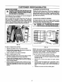
CUSTOMER
RESPONSIBILITIES
Read and observe the safety rules.
FoIIow regular schedule in maintaining, caring for and
using your high pressure washer.
•
HEIGHT
SPARK PLUG:
MAINTENANCE
•
Not to exceed 140°F
Fol}ow the instructions under "Customer Responsibilities" and "Storage" sections of this Owner's Manual.
NOTE: The engine of the pressure washer is equipped with
a spark arrestor muffler, The spark arrestor must be maintained in effective working order by the owner/operator` .
In the State of California a spark arrestor is required by law
(Section 4442 of the California Public Resources Code).
Other states may have similar laws, Federal laws apply on
federal lands.
TABLE 0F CONTENTS
SAFETY RULES ............................................................
2
PRODUCT SPECIFICATIONS
3
ACCESSORIES
......................................
......................
5
CONTENTS OF HARDWARE PACK .............................
AND ATTACHEMENTS
6
ASSEMBLY ..................................................................
OPERATION ..............................................................
-AAir Cteaner .............
Assembly
Removingfrom Cation .........
Tools Required ...............
Set Up ....................
9,16
7
7
7-8
WARRANTY
Hardware Pack ............
6
15
16
16
Spark Arrestor...............
18
-E17
8,9
Repair Parts ...........
20-26
-S13
Safety Latch .............
12
Safety Rules ..............
2
Service and Adjustments.
17-18
Storage .................
18
Engine ....................
18
Pressure Washer Pump .......
18
15
15
-TTroubleshooting
-OOil, Engine .............
Operation
Detergent Application........
Stopping...................
To Start Engine .............
ToTum On Washer ..........
To Use ....................
..........
19
3,11
-V11
10
12
12
10
Valve, thermal relief .......
10
13
-WWarranty ................
-pPressure Regulator ........
G
27
6.8
-M-
Pump .....................
Replace Spark Plug ..........
ServiceAir Cleaner ...........
20-26
-R-
11-12
Maintenance
Engine ....................
Pump .....................
PARTS .........................................
18I
19 _
.................................................................
-LLow Oil Pressure System ...
Customer Responsibilities
Statement...................
3
Schedule................
14-16
ChangingOil................
15
Checking Oil Level ...........
15
General Recommendations .... 14
Pressure Washer ............
14
Gun and Wand Assembly...
REPLACEMENT
High Pressure Hose .......
-C-
Engine Speed ............
9-13
STORAGE ....................................................................
TROUBLESHOOTING ..................................................
-H-
-BBefore Starting .........
7-8
CUSTOMER RESPONSIBILITIES .......................... 14-16 (
SERVICE AND ADJUSTMENTS .................................. 177
27
ACCESSORIES
AND ATTACHMENTS
These accessories and attachments were available when the high pressure washer was purchased. They are also
vailable at most Sears retail outlets and service centers. Most Sears stores can order these items for you when you
,_rovide the model number of your high pressure washer. Some of these accessories may not apply to your pressure
asher.
@
i
i
-
i
i
L_
-L=_
1
r
!
f
1
I
1
i
J
@
ROTATING BRUSH
KIT
FLOOR/SIDING
BRUSH KIT
ACCESSORY
QUICK CONNECT
ACCESSORY
QUICKCONNECT
STARTER KIT
t800 PSi (max.)
TURBO HEAD
2200 and 2500 PSI (max.)
HIGH PRESSURE
HOSE TO HOSE
COUPLING
MULTI*PURPOSE/HOUSE
WASH
ANGLE EXTENSION
KIT
CHEMICALINJECTION
FOAMER
,,,,, ,,,,.
TURBO HEAD
ELECTRIC TURBO
NOZZLE
18"STAINLESS
STEEL EXTENSION
3/8" I,D. 50 ft. EXTENSION
HOSE
1/4" I,D, 25 ft, EXTENSION
HOSE
HIGH PRESSURE
HOSE QUICK CONNECT KIT
UTILITY BRUSH KIT
J
GARDEN HOSE
QUICK CONNECT
WiTH 2 ADAPTORS
PRESSURE
GAUGE
,,
DECK WASH
VEHICLFJBOAT
WASH
DEGREASER
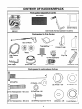
CONTENTS
OF HARDWARE
PACK
Parts packed separately in carton
Parts Carton
(
Owner's Manual
Guide Handle Assembly (packed in flat carton)
Main Unit
Parts packed in Parts Carton
Detergent
Pickup
Tube and Filter
(2) Support Legs
Motor Oil
Wheels
Nozzle Cleaner
Kit
High Pressure
Hose
Wire Support
Vinyl Cap
Oil Fill Cap/Breather
(2) Push Nuts - 1/2"
Quick-Connect
Adjustable Nozzle
Parts packed in carton shown full size
(2) Axle Pins
(2) Washers - #10
©
lllI!II!fl!lllllltlttttlltllliiiitiB
2) Hex Head Capscrews- M8 x 40mm
(2) JAM Nuts - 5/8"
(2) Washers - M12
(6) FlangeNuts- M8
tlttlllllNllll!ll
4) He× Head Cap_mws
- M8 × 20ram
(2) Self-drillingCapscrews- #10-16
(2) Washers - M8
(2) LockWashers - 5f(
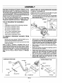
ASSEMBLY
Read these instructions and Operator's Manual in its entirety before you attempt to assemble or operate your new
high pressure washer. Your high pressure washer has, for
he most part, been assembled at the factory, except those
)arts left unassembled. Before you can operate your new
high pressure washer, you must assemble the wheel kitand
properly connect the high pressure hose.
HOW TO SET UP YOUR
REQUIRED
•
Prop up the engine end of the main unit. This will allow
you to slip each axle pin into the holes provided on the
side of the base (Fig. 1).
JAM NUT
AXLE
FOR ASSEMBLY
•
Mallet
•
2 adjustable wrenches OR the following wrenches:
•
5/16" (8mm) combination wrench
•
1/2" (13ram) combination wrench
,,
5/8" (16ram) combination wrench
,,
11/16" (18mm) combination wrench
,,
7/8" (22mm) combination wrench
,1
15/16" (24mm) combination wrench
TO REMOVE
CARTON
PRESSURE
WASHER
Installing the wheel kit requires the tools listed, the guide
handle and items included in the parts carton.
IF YOU HAVE ANY PROBLEMS WITH THE ASSEMBLY
OF YOUR PRESSURE WASHER, PLEASE CALL THE
PRESSURE WASHER HELPLINE AT 1-800-222-3136.
TOOLS
PRESSURE
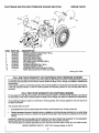
TO INSTALL THE WHEEL KIT
REVERSEANGLE
PUSHNUT
WASHER
WHEEL
FROM
HG. 1
Remove two boxes marked "PARTS INSIDE" and remove the parts contained in both boxes.
•
With the axle pin inserted inside the base, grip the end
of the axle pin as shown with an adjustable or 15/16"
combination wrench. This will keep the axle from spinning as you fasten the axle to the base with a 5/8" lock
washer, a 5/8"-18 JAM nut, and an M 12 flat washer.
t
Place wheels on the axles so the valve side of hub is
facing outward.
•
Retain each wheel to its axle p in by tapping a push nut
onto end of axle with a malle t.
o
Attach support legs to base as shown in Fig. 2 with M8
x 20mm hex head capscrews and flange lock nuts.
Tighten with 13mm or 1/2-inch wrench on each fastener. Be sure tegs are straight when you are finished.
Remove unit with one hand under pump and one hand
under recoil starter.
Refer to Page 6, "Contents of Hardware Pack" for an
illustrated listing of all the items included with your pressure
washer. Become familiar with each piece before assembling the pressure washer. Check all contents against the
illustrations on Page 6. If any parts are missing or damaged, call the Pressure Washer Helpline at 1-800-222.
3136.
Attach the guide handte to the base as shown in Fig. 2
with two M8 x 40mm hex head capscrews, two M8
washers and two flange nuts.
Installing the Guide Handle
Installing
CAPSCREW
Support Legs
GUIDE
HANDLE
HEX NUT
SUPPORT LEG
WASHER
\,
WIRE SUPPORT
NUT
CAPSCREW
FIG.2
ASSEMBLY
•
Attach wire support to two lower holes in guide handle
with # 10 self-drilling screws and # 10 fiat washers (Fig.
3). The hose minder should be to the left and gun holder
to the ri_ht. Be sure loop of support is pointing upward.
Place vmyt cap onto gun holder.
VINYL CAP
Screen in water inlet for cleanliness and inspect Inlet
Screen on female connector. Reattach male connector
to water inlet and attach female connector to garden
hose.
•
I
/
Unravel high pressure hose, remove protective cap
from end of hose and check other end of hose to see
that threads are properly covered with teflon tape. If
tape is not properly applied, reapply it so threads are
fully covered. The tape seals the connection from hose
to gun and wand assembly.
Attach fitting with teflon tape to gun and wand assembly
(Fig. 6). You may want to spin gun. Tighten with adjustable wrench to keep hose from twisting.
GUIDE
HANDL_
/
WIRE
SUPPORT
FIG.3
TO ASSEMBLE
REMAINING
COMPONENTS
IMPORTANT: YOU MUST ASSEMBLE WAND AND ATTACH ALL HOSES BEFORE YOU START ENGINE.
STARTING
ENGINE WITHOUT ALL HOSES CONNECTED AND WATER SUPPLIED
WILL DAMAGE
PUMP,
•
FIG. 6
Attach the other end of the high pressure hose to high I
pressure fitting on pump (Fig. 7). Tighten with adjustabte wrench.
DETERGENT PICKUP TUBE
Remove cap from top of
pump and insert oil fill
cap attached to other
end of yellow waming
tag,
•
HIGH PRESSURE
HOSE
FIG. 4
Included with this unit is a Quick-Connect fitting you
attach to Water Inlet on pump, The quick-connect
includes two parts -- a Male Connector factory-installed on water inlet and a Female Connector (Fig. 5).
Remove male connector to inspect Intake Supply
INTAKE SUPPLY
FIG. 7
,,
Attach Detergent Pickup Tube and Filter as shown in
Fig. 7.
o
To attach the adjustable
section, Fig. 9,
OPENING
_R'AKESUPPLY FILTER
nozzle,
refer to Operation
CHECKLIST
FEMALECONNECTOR
MALE
INLET SCREEN
FIG. 5
•
Check that fasteners you used to install wheels and
handle are tight. Vibration during operation may
loosen fasteners that are not tight enough,
•
Check for proper hose connections (high pressure and
water supply) and for tight connections and that there
are no kinks, cuts, or damage to the high pressure
hose.
o
Provide proper water supply (not to exceed 140°F).
•
Be sure to read "Safety Rules" and "Operation"
tions before using the pressure washer,
se_
OPERATION
KNOW YOUR HIGH PRESSURE WASHER
READ THIS OWNER'S MANUAL AND SAFETY RULES BEFORE OPERATING YOUR HIGH PRESSURE WASHER.
Compare the illustrations with your high pressure washer to familiarize yourself with the locations of various controls and
adjustments. Save this manual for future reference.
DETERGENT
AND FILTER
WIRE SUPPORT FOR
GUN AND HOSE STORAGE
PICKUP TUBE
OIL FILL OPENING
MUFFLER
ENGINE ON-OFF
HIGH PRESSURE OUTLET
STARTER
GUIDE HANDLE
GUN AND WAND
ASSEMBLY
PUMP
PRESSURE
REGULATOR
HIGH PRESSURE HOSE
tNL:_T SCRE_
QUICK-CONNECT
FIG. 8
PUMP n Develops high pressure.
PRESSURE REGULATOR -pressure of the outlet stream.
Allows you to adjust the
ENGINE ON-OFF CONTROL -- Sets engine in starting
mode for recoil starter; turns OFF running engine.
RECOIL STARTER -ally.
Used for starting the engine manu-
AIR CLEANER - Dry type filter element limits the amount
"f dirt and dust that gets in the engine.
GUN AND WAND ASSEMBLY--Controls
the application
of water onto cleaning surface with trigger device, Includes
safety latch.
INTAKE SUPPLY FILTER -- Filters inlet water supply.
DETERGENT PICKUP TUBE AND FILTER -- Mixes water
and detergent in outlet water flow.
HIGH PRESSURE OUTLET R Connection for high pressure hose.
QUICK-CONNECT
supply.
--
Easy connection for intake water
OPERATION
HOW
TO USE
YOUR
WASHER
IF YOU HAVE ANY PROBLEMS OPERATING YOUR
PRESSURE WASHER, PLEASE CALL THE PRESSURE
WASHER HELPLINE AT 1-800-222-3136.
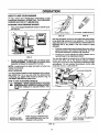
STOPPING YOUR PRESSURE WASHER
.
First, move engine RUN/STOP switch to "STOP" position (Fig, 9).
ADJUSTAB_ .= NOZZLE
OPTIONAL TURBO NOZTLE
FIG. 10
FIG. 11
With the adjustable nozzle you can adjust the spray pattern
to be either high pressure or low pressure. You can also
adjust the spray so it is concentrated in a stream pattern or
expanded into a fan pattern. Use this nozzle to apply
detergent.
=
Push the nozzle attachment forward when you wish to
adjust the spray to low pressure mode (Fig. !2). Push
the nozzle backward to achieve high pressure.
•
Twisting the nozzle adjusts the spray pattern from a
narrow stream to an expanded stream.
FIG.9
,
You can also adjust the pressure by turning the pressure
control knob (Fig. 13) to the desired pressure setting.
Turning this knob all the way clockwise produces the highest pressure. Do not unscrew the pressure control valve,
more than 3 turns, it will come off,
Simply shutting OFF engine will not release pressure in the system. Pull the trigger on the spray wand
assembly to relieve the pressure in the hose.
NOTE: A small amount of water will squirt out when you
release the pressure.
SPRAY NOZZLES
DECRF__..ASEPRESSURE
Your high pressure washer comes equipped with an adjustable nozzle (Fig. 10) or you can order the optional turbo
nozzle (Fig. 11). Attach either nozzle as shown in Fig, 10
and HAND TIGHTEN the plastic knob,
HOW TO USE ADJUSTABLE
,_
NOZZLE
WARNING:
NEVER
ADJUST
PATTERN
WHEN
SPRAYING,
NEVER
PUTSPRAY
HANDS IN
FRONT
OF SPRAY NOZZLE TO ADJUST SPRAY PATTERN.
NOZZLE IN HIGH
PRESSURE MODE
FIG. 13
PUSH NOZZLE FORWARD FOR
LOW PRESSURE MODE AND DETERGENT APPLICATION
TWIST NOZZLE TO
EXPAND SPRAY
FIG. 12
10
TWIST NOZZLE TO NARRC_w_'/
SPRAY STEAM
OPERATION
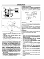
APPLIYiNG DETERGENT
NOZZLE
WITH ADJUSTABLE
o
Hbok up water supply (Fig. 16) and turn ON water.
o
NOTE: Be sure female quick-connect
erly onto male connector.
IMPORTANT: USE SOAPS DESIGNED SPECIFICALLY
--OR PRESSURE WASHERS.
HOUSEHOLD DETER3ENTS COULD DAMAGE THE PUMP.
IMPORTANT:
YOU MUST A'I-I'ACH ALL HOSES BEFORE YOU START THE ENGINE. STARTING THE ENGINE WITHOUT ALL THE HOSES CONNECTED WILL
DAMAGE THE PUMP.
QUICK-CONNECT
WATER SUPPLY
Pressure washers are useful cleaning tools designed to
clean almost any surface in two easy steps.
•
=
The first step involves applying an appropriate detergent/solvent solution to penetrate and loosen grime.
The detergent is applied at low pressure to avoid
splashing, overspraying and waste. Leavethe solution
on surface for 3 to 5 minutes to allow solution to worK.
FIG, 16
The second step involves cleaning the surface you
have prepared with the pressure washer and then
rinsing it clean.
•
•
Prepare your detergent
solution as required by
your job.
Place small filter of the
clear, detergent syphoning tube into the detergent container (Fig. 14).
Detergent will not flow when in the high pressure
Start washer and work from the top of the surface to
the bottom.
NOTE: The high pressure mode is most effective when the
tip of the wand is held between 8 inches to two feet from
the surface being cleaned.
HOW TO USE OPTIONAL TURBO NOZZLE
Set nozzle to low pressure mode. Detergent is
not siphoned in the high
pressure mode (Fig. 12).
Start washer and apply
detergent to a dry surface, starting from the
bottom and working up.
Adjust nozzle to select high pressure mode.
NOTE:
mode.
To apply detergent follow these steps:
•
is installed prop-
FIG. 14
•
The optional rotating turbo nozzle, in essence, expands
the area of the high pressure stream.
o
You cannot adjust the spray pattern with this nozzle,
=
You cannot apply detergent with this nozzle.
BEFORE
STARTING
THE ENGINE
INCREASE
To operate the engine you will need the following:
MIXTURE
ENGINE OIL
o
Adjust the concentration
of detergent by turning
the knob on the detergent injector (Fig. 15).
IMPORTANT: ANY ATTEMPT TO CRANK OR START
THE ENGINE BEFORE IT HAS BEEN PROPERLY SERVICED WITH THE RECOMMENDED OIL RESULTS tN AN
ENGINE FAILURE,
=
To stop flow of detergent, turn knob clockwise, remove filter from
detergent or set nozzle
to high pressure.
A 20 oz. bottle of SAE 30 weight oil is included in the parts
carton.
FIG. 1S
NOTE: When adding oil to the engine crankcase in the
future, use only high quality detergent oil rated with API
service classification SC, SD, SE, SF, SG rated SAE 30
weight. Use no special additives. Select the oil's viscosity
grade according to your expected operating temperature.
NOTE: Detergents are most effective when applied to a dry
surface.
PRESSURE
WASHING/RINSING
ii
WARNING:
BE EXTREMELY
IF YOU
MUST USE PRESSURE
WASHERCAREFUL
FROM LADDER,
SCAFFOLDING OR ANY OTHER RELATIVELY UNSTABLE LOCATION. PRESSURE IN A RUNNING
WASHER BUILDS IN THE WAND AS YOU CLIMB.
WHEN YOU PRESS THE TRIGGER, THE RECOIL
FROM THE INmAL SPRAY COULD FORCE YOU
TO FALL, OR IF YOU ARE TOO CLOSE TO THE
CLEANING SURFACE, HIGH PRESSURE COULD
FORCE YOU OFF CLIMBING APPARATUS.
colder 5W30
ii
i
32°F
|
iiiiiii
SAE30 warmer
Although multiwiscosity oils (5W30, t0W30, etc.) improve
starting in cold weather, these multi-viscosity oils will result
in increased oil consumption when used above 32°F.
Check your engine oi! level more frequently to avoid possible damage from running low on oil. Oil sump capacity is
20 ounces.
11
l
OPERATION
ADD ENGINE OIL:
•
Clean area around fuel fill cap, remove cap.
*
,,
Add =UNLEADED"
tank.
Place pressure washer on a level surface and remove
one of the yellow Oil Fill Caps (Fig, 17) and add engine
oil from the enclosed bottle unttl level is at point of
overflowing. Check engine oil level before starting
each time thereafter. If oit level is below point of
overflowing, fill to proper level. Crankcase oil capacity
is about 620ml or 21 fluid ounces,
regular gasoline, slowly, to fuel I
•
Install fuel cap and wipe up any spilled gasoline.
TO TURN ON WASHER
•
Attach one end of a garden hose to a cold water source.
Water supply should not exceed ! 40°F (55°C).
•
Check that high pressure hose is attached to pump
outlet and that water supply is attached to pump inlet.
Turn ON water.
•
•
Press trigger on gun and wand assembly to force air
from high pressure hose.
•
Start engine according to "TO START THE ENGINE."
TO START
THE
ENGINE
IMPORTANT:
DO NOT RUN
WATER SUPPLY CONNECTED
AND OPENING
PUMP WITHOUT THE
AND TURNED ON.
,,
Start, store and fuel the unit in a level position.
•
Open fuel shut-off valve.
Press trigger on pressure washer wand to relieve high
pressure and/or purge the inlet hose of air.
,,
FIG, 17
•
...........
Adjust safety latch on spray gun to the ON position.
This disables the trigger so you cannot inadvertently
actuate a high pressure spray (Fig. 18).
THE ENGINE BEFORE IT HAS BEEN PROPERLY
SERVICED
WITHATTEMPT
THE RECOMMENDED
RECAUTION: ANY
TO CRANK OROIL
START
SULTS IN AN ENGINE FAILURE.
ADD GASOUNE:
ALWAYS
ALLOW
ROOM
FORFUEL
EXPANSION.
t OFF
NEVER
FiLLFUELTANKWHENENGINE
iSRUN-I
! _lb
NINGORHOT.DONOT
ORII
WARNING:
NEVER FILLLIGHT
FUELACIGARETTE
TANK INDOORS.
SMOKE WHEN FILLING FUEL TANK.
TRIGGER
•
Use regular UNLEADED gasoline with the pressure
washer engine. Regular leaded gasoline may also be
used if UNLEADED is not available. Fuel tank capacity
is I U.S. gallon.
IMPORTANT:
IT IS IMPORTANT TO PREVENT GUM
DEPOSITS FROM FORMING tN ESSENTIAL FUEL SYSTEM PARTS SUCH AS THE CARBURETOR, FUEL FILTER, FUEL HOSE OR TANK DURING STORAGE. ALSO,
EXPERIENCE INDICATES THAT ALCOHOL-BLENDED
FUELS (CALLED GASOHOL OR USING ETHANOL OR
METHANOL) CAN ATTRACT MOISTU RE WHICH LEADS
TO SEPARATION AND FORMATION OF ACIDS DURING
STORAGE, ACIDIC GAS CAN DAMAGE THE FUEL SYSTEM OF AN ENGINE WHILE IN STORAGE, TO AVOID
ENGINE PROBLEMS, THE FUEL SYSTEM SHOULD BE
EMPTIED
BEFORE
STORAGE
OF 30 DAYS OR
LONGER. SEE "STORAGE" ON PAGE 18. NEVER USE
ENGINE OR CARBURETOR CLEANER PRODUCTS IN
THE FUEL TANK OR PERMANENT DAMAGE MAY OCCUR.
_
_ t
'J
t
\\
\
FIG. 18
]2
*
Locate the Run!Stop switch (Fig. 19 on Page 13) next
to the engine cylinder head and set it to RUN.
o
Close the choke to FULL position (Fig. 20 on Page 13)
by sliding it to far position in direction indicated by arrow
on air cleaner housing.
t
Turn pressure control knob counterclockwise,
turns from maximum pressure.
e
Grasp the starter grip and pull slowly until you feel
resistance. Then pull rapidly.
=
When engine starts, move choke lever to "RUN" position. If engine fails to start, move choke lever to "RU__
position and pull starter rope (maximum 2 pulls).
•(
.
If engine fails to start, repeat the previous two stepsr_
two
OPERATION
i
SENSING LOW PRESSURE
If the system senses tow oil pressure during operation, the
engine shuts down. As the system shuts down, the low oil
light comes ON. However, once the engine has stopped
rotating, this light will go OFF. See Fig. 21 for schematic.
(
_E_;SURE
L_;D
_
L
i
_
FGRN_-I
L _
FIG. 19
[
HO_"JLg
_tlG
RUN
sP
.LuG
Oi I
-
GRN
0
J _.
CNO.
)G_£1"(())_
FIG. 21
RESTARTING
If you try to restart the engine within 10 seconds after it
shuts down, the engine may NOT start. The system needs
5 to 10 seconds to reset,
FULL
if you do restart the engine after such a shutdown and
have not corrected the low oil pressure, the engine
runs for about 10 seconds as described above and then
stops,
RUN
SIPHONING
We recommend that you DO NOT siphon your water supply. Connect only to household water supply.
FIG. 20
-
Once engine has started, place Safety Latch in OFF
position.
•
Press trigger on gun and wand assembly.
should spray out the nozzle.
•
Adjust nozzle for correct pressure and spray angle.
You can also turn the pressure control knob to your
desired pressure setting.
TIPS
Water
•
Your pressure washer is ready to use.
IMPORTANT: AN INTERNAL THERMAL RELIEF VALVE
HAS A MAXIMUM TEMPERATURE SETTING OF 140°F
(60°C). IF YOU RUN THE PUMP FOR 5 MINUTES WITHOUT PRESSING THE TRIGGER ON THE SPRAY GUN,
1/2 TO 1 OUNCE OF WATER iS RELEASED THROUGH
THE VALVE TO COOL THE UNIT. THE SMALL AMOUNT
OF WATER WILL DRIP OUT THE BOTTOM OF PUMP.
LOW OIL PRESSURE
SHUTDOWN
•
Initially clean an area and then check the surface for
damage. If no damage is found, you can assume it is
okay to continue cleaning. Detergents work best when
applied to dry surface.
o
For most effective cleaning, keep spray nozzle between 8 to 24 inches of cleaning surface.
•
Allow the detergent to soak in between 3-5 minutes
before washing and rinsing.
•
For cleaning, start at lower portion of area to be washed
and work upward, using long, even overlapping
strokes.
•
For rinsing, push the nozzle sleeve to high pressure
and wait for detergent to clear. Start at the top of area
to be rinsed, working down with the same action as for
cleaning.
SYSTEM
@
The engine is equipped with a low oil pressure sensor that
shuts down the engine automatically when the oil pressure
drops below 6 psi. If the engine shuts down by itself and
the fue! tank has enough gasoline, check engine oil level.
Never use the garden hose inlet to siphon detergent or
wax.
o
TIAL STARTUP
delay built in the shutdown system allows oil pressure to
_ldduring starting. The delay allows the engine to run for
out 10 seconds before sensing oil pressure.
]3
If you get the spray nozzte too close, especially using
high pressure mode, you may damage the cleaning
surface.
o
If you have the spray nozzle too far away the cleaning
will not be as effective.
o
Do not get closer than 6 inches when cleaning automobile tires.
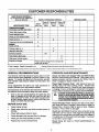
CUSTOMER RESPONSIBILITIES
MAINTENANCE SCHEDULE
RLL IN DATESASYOUCOMPLETE
REGULARSERVICE
HOURLY OPERATING
Every25
Hours or
Yearly
Before
EachUse
MAINTENANCE TASK
PRESSURE WASHER
Check/cleaninletfilter and screen
INTERVAL
Every50
Hoursor
Yeady
SERVICE DATES
Every 100
Hours or
Yeady
XV
Check highpressure hose.
X
Check detergenthose.
X
Check gunand wand for leaks.
X
X
Check pumpoil. •
Purgepumpof air and con_nirnents _
ENGINE
Check oillevel.
X
,
X
Change engine oil. •
X*
Retorquehead bolts.
Serviceair cleaner.
X
X**
Clean/replacespark plug.
X
Clean spark arrestorscreen.
X
Preparefor storage.
Prepare unitfor storageif it isto remain idle
longer than 30 days
V Cleanif dogged. Replaceifperforated
or torn.
*Change, scoam'when
GENERAL
oporati_,g u_texheavyloadorhighambi_nt
t Changeoilafterfirst8 hours,thenafterevery50 hours.
temperature. _* Cle_anrao_oft_n_m6vrdustyconditionsorwhenalrborncdebrisls
RECOMMENDATIONS
PRESSURE
The warranty of the high pressure washer does not cover
items that have been subjected to operator abuse or negligence. To receive full value from the warranty, operator
must maintain high pressure washer as instructed in this
manual.
Some adjustments will need to be made periodically
properly maintain your high pressure washer.
Check High Pressure Hose: High pressure hose can
develop leaks from wear, kinking, abuse. Inspect hose
each time before using it. Check for cuts, leaks, abrasions
or bulging of cover, or damage or movement of couplings.
If any of these conditions exist, replace hose immediately.
to
A
Once a year you should replace the spark plug and
clean or replace the air filter and check the gun and
wand assembly for wear. A new spark plug and clean
air filter assure proper fuel-air mixture and help your
engine run better and last longer.
Check engine oil level.
•
Check water inlet filter and quick-connect screen for
damage.
•
Check high pressure hose for leaks.
t
Check detergent inlet hose and fitter for damage.
=
•
Check gun and wand assembly for leaks.
Purge pump of air and contaniments.
DANGER: WATER SPRAYING FROM A LEAK IS CA- I
PABLE OF INJECTINGMATERIALINTOSiON.NEVER [
REPAIR HIGH PRESSURE HOSE. REPLACE WITH
HOSETHATMEETS
MINIMUMPRESSURERATINGOF
YOUR PRESSUREWASHER,
Check Detergent Hose: Examine the filter on the detergent hose and clean if clogged, Hose should fit tightly on
barbed fitting. Examine hose for leaks or tears. Replace
the filter or hose if either is damaged.
EACH USE
•
MAINTENANCE
Check and Clean Inlet Supply Filter and Inlet Screen:
Remove quick-connect and examine inlet screen on the
female connector and filter on pump inlet fitting. Clean if
either is clogged or replace if either is tom.
All adjustments in the Service and Adjustments section of
this manual should be made at least once each season.
BEFORE
WASHER
pr_se_
Check Gun and Wand: Examine hose connection to gun
and make sure it is secure. Test trigger by pressing it and
making sure it springs back into place when you release it.
Put safety latch in ON position and test trigger. You shoulF
not be able to press trigger.
Check Pump Oil: Refer to PUMP MAINTENANCE
information.
]4
fQ_
CUSTOMER
RESPONSIBILITIES
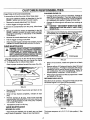
CHANGING ENGINE OIL
Purge Pump of Air and Contaniments:
To remove the air from the pump, follow these steps:
,
o
Change oil after first 8 hours of operation. Change oil
every 50 hours thereafter, tf you are using your pressure washer under extremely dirty or dusty conditions,
or in extremely hot weather, change oil more often.
•
Change oil while engine is still warm from running, as
follows:
Set up the pressure washer as described in the ASSEMBLY section and connect the water supply.
Remove the nozzle attachment from the gun.
•
Pull the trigger on the gun and hold.
To remove the contaniments from the pump, follow these
steps:
•
Set up the pressure washer as described in the ASSEMBLY section, connect the water supply and start
the engine according to instructions in the OPERATION section.
•
Remove the nozzle attachment from the gun.
o
Pull the trigger on the gun and hold.
=
When the water supply is steady and constant, you may
refasten the nozzle attachment and stad the pump.
PUMP
A
A
•
FROM SPARK PLUG AND KEEP IT AWAY FROM
CAUTION: DISCONNECT SPARK PLUG WIRE i
SPARK PLUG,
Clean area around oildrain plug, remove plug and drain
oil completely into a suitable container (Fig. 23).
MAINTENANCE
OIL DRAIN
PLUG
PLUG
WARNING: DO NOT A'n'EMPT TO DISASSEMBLE
THE PUMP. WITHOUT THE PROPER TECHNIQUE,
AI"FEMPTING
TO DISASSEMBLE
PUMP MAY
CAUSE PERSONAL INJURY. FOR SERVICE, CONSULT A SEARS AUTHORIZED SERVICE CENTER
OR CONTACT YOUR PLACE OF PURCHASE.
CONTAINER
'ump Oil: Change pump oil after first 50 hours of opera•_on. Change pump oil every time you change the engine
,il. To change pump oil, follows these steps:
FIG. 23
*
When oil has drained, install and tighten the oil drain
plug.
o
Remove yellow oil fill plug and insert a clean fill funnel
into plug opening. Fill engine crankcase with recommended oil until oil level is at point of overflowing. Do
not overfill above the point of overflowing.
,&.bout21
ounces (620ml) is required. POUR SLOWLY.
Place a proper container beneath the pump (Fig. 22).
=
When engine crankcase is filled to proper level. Install
and tighten oil fill plug.
RETORQUE HEAD BOLTS
After 50 hours of operation, retorque the head bolts for this
GN-Series engine to 4.0 kg/m (29 foot-pounds).
FIG. 22
•
Remove the Oil Drain Plug of pump and drain oil into
the container.
•
When oil has drained completely, reinstall oil drain
plug.
•
Remove pump's oil fill plug, insert funnel and add
recommended SAE 80W-90 oil until level reaches full
mark on gauge located on side of the pump. Capacity
is 5 ounces (150 grams).
•
Reinstall the pump's oil till plug.
31GINEMAINTENANCE
FIG. 24
NECKING OIL LEVEL
The torque sequence is A, B, C, D, E (star pattern).
Fig 24.
' level should be checked prior to each use or at least
_4ery 5 hours of operation. Keep oil level maintained.
]5
See
CUSTOMER RESPONSIBILITES
SERVICE AIR CLEANER
CLEAN/REPLACE
ABk COMPLETE AIR CLEANER SYSTEM INSTALLED
ON
THE ENGINE.
COULD
RESULT
IN PREA
CAUTION:
NEVER THIS
RUN THIS
UNIT
WITHOUTTHE
MATURE WEAR TO THE ENGINE.
Your engine will not run propedy and may be damaged if
you run it using a dirty air cleaner.
Clean or replace the air cleaner paper filter (Fig. 25) once
every 25 hours of operation or once a year. whichever
comes first, Clean or replace more often if operating under
dusty or dirty conditions. Clean foam pre-filter every 25
hours of operation or sooner under dusty conditions,
SPARK PLUG
Change the spark plug every 100 hours of operation or
once each year, whichever comes first. This will help your
engine to start easier and run better. Replace with Champion RC12YC or equivalent type spark plug. Set spark plug
gap 0+030 inch (0.76mm).
CLEAN SPARKARRESTORSCREEN
The engine exhaust muffler has a spark arrestor screen.
Inspect and clean the screen every 100 hours of operation
or once each year, whichever comes first.
,_
CLEANER
WARNING:
LET
MUFFLER
COOL
BEFORE
WORKING ON
IT, THE
CONTACT
WITH
A HOT
MUFFLER OR ENGINE CAN CAUSE SEVERE BURNS,
SPARK
l
FIG. 25
To clean or replace foam pre-fitter:
=
Remove air cleaner cover, then foam pre-filter,
=
Wash pre-filterin soap water. Squeeze pre-cleaner dry
in clean cloth (DO NOT TWIST).
+
Clean air cleaner cover before installing it.
FIG. 26
NOTE: If you use your pressure washer on any forest-covered, brush-covered or grass-covered unimproved land, it
must have a spark arrestor. The spark arrestor must be
maintained in good condition by the owner/operator.
To clean or replace paper air filter:
Clean and inspect the spark arrestor as follows:
+
Remove air cleaner cover; then remove foam pre-filter
(service if necessary) and remove paper filter.
-
.
Clean air filter by tapping it gently on a solid surface, tf
the filter is too dirty, replace it with a new one. Dispose
of the old filter properly,
To remove the muffler guard from the muffler, remove
the three screws that connect the guard to the muffler
bracket (Fig. 26).
+
Remove
screen.
•
Inspect screen and replace if torn, perforated or otherwise damaged. DO NOT USE a defective screen. If
screen is not damaged, clean it with commemial solvent.
+
Clean air cleaner cover then insert pre-filter into cover.
Next insert new paper filter into cover to hold pre-filter
in place and assemble all of them to the base of the air
cleaner.
four screws that attach the spark arrestor
Reattach the screen and the muffler guard.
16
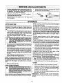
SERVICE AND ADJUSTMENTS
ENGINE
A
SPEED
CAUTION: ATENGINE
SPEED WAS
JUSTED
THE FACTORY
ANDPROPERLY
SHOULD ADRE-
QUIRE NO ADDITIONAL ADJUSTMENT. DO NOT
ATTEMPT TO CHANGE ENGINE SPEED. IF YOU
BELIEVE THE ENGINE IS RUNNING TOO FAST OR
TOO SLOW, TAKE YOUR PRESSURE WASHER TO
SEARS AUTHORIZED SERVICE CENTER FOR REPAIR AND ADJUSTMENT, CHANGING ENGINE
GOVERNED SPEED WILL VOID ENGINE WARRANTY.
FEELER
ALLEN
GAUGE
',LOOSEN
JAM NUT
Your pressure washer runs at a constant speed. This
constant operating speed is maintained by a mechanical,
flyweight type, fixed speed governor. DO NOT try to adjust
the governed speed setting for the following reasons:
,,
High engine speeds are dangerous and increase the
risk of personal injury or damage to equipment.
FIG. 27
Low engine speeds impose a heavy load on the engine
when sufficient engine power is not available and may
shorten engine life.
ADJUSTING
VALVE
CLEARANCE
After the first 50 hours of operation, you should adjust the
valve clearance in the engine.
When adjusting valve clearance, engine should be
_.mperature and piston should be at Top Dead
, I'DC) of compression stroke (both valves closed).
learance is 0.05-0.1mm. Adjust valve clearance
at room
Center
Correct
as fol-
ws:
=
,,
Loosen the rocker arm jam nut. Use an allen wrench
to turn the pivot ball stud while checking clearance
between the rocker arm and the valve stem with a feeler
gauge (Fig. 27).
When valve clearance is correct, hold pivot ball stud
with allen wrench and tighten rocker arm jam nut with
crows foot. Tighten jam nut to 65-85 inch-pounds
torque. After tightening jam nut, recheck valve clearance to make sure it did not change (Fig. 28).
NOZZLE
Tighten jam nut to
65,.85 inch-pounds
_7-10 N-m).
FIG. 28
MAINTENANCE
If the nozzle becomes restricted or clogged with foreign
materials, such as dirt, excessive pump pressure may
develop. A partially clogged nozzle can cause a pulsing
sensation during use. This generally is not a pump related
problem, but rather a clogged or partially restricted nozzle.
If the nozzle becomes clogged or partially restricted, immediately clean the nozzle with the kit included with your
pressure washer by following these instructions:
•
Shut off the engine and turn off the water supply.
=
Separate the wand from the gun.
,,
Remove nozzle from the end of the wand using a 2ram
or 5/64 allen wrench (like the one included in the kit).
Use the wire included in the kit (Fig. 29) or a small paper
clip to free the foreign materials clogging or restricting
the nozzle.
Insert wire intonozzle andturn back andforth to clearobstruction
FIG. 29
17
SERVICE AND ADJUSTMENTS
o
I
o
Remove additional debris by back flushing water supply through wand (Fig. 30). Back flush between 30 to
60 seconds. Turn wand to stream spray and move
nozzle from low to high while flushing.
•
Test the pressure washer by operating with nozzle in
the high and in the tow position.
i
<3;a
Reinstall nozzle into the wand. DO NOT overtighten.
Reconnect the wand to the gun
,
Reconnect the water supply, tum on the water, and
start the engine.
FIG. 30
STORAGE
AFTER
EACH
NOTE: As always, prepare the pressure washer pump as
you would after each use.
USE
Water should not remain in the unit for long periods of time.
Sediments of minerals can deposit on pump parts and
"freeze" pump action. Follow these procedures after every
use:
It is important to prevent gum deposits from forming in
essential fuel system parts such as the carburetor, fuel
filter, fuel hose or tank during storage. Also, experience
indicates that alcohol-blended fuels (called "gasohol" or
using ethanol or methanol) can attract moisture which leads
to separation and formation of acids during storage. Acidic
gas can damage the fuel system of an engine while in
storage.
Flush detergent hose by placing the injector filter into
a pail of clear water while running Pressure Washer
with nozzle in low pressure mode. Rush until you can
see clear water running through the tube.
Shut off the engine and let it cool, then remove all
hoses.
To avoid engine problems, the fuel system should be
emptied before storage of 30 days or longer. Follow these
instructions:
CAUTION: BE SURETHE THROTTLE LEVER IS IN I
"STOP" POSITION BEFORE YOU CONTINUE. IF 1
YOU STARTTHE ENGINE wrrHOUT THE PROPER I
WATER SUPPLY CONNECTED, YOU CAN DAMAGE THE PUMP.
t
Protect Fuel System: Engines stored over 30 days need(
to be protected or drained of fuel to prevent gum deposits
from forming in fuel system or on essential carburetor parts
•
Empty the pump of all pumped liquids by pulling recoil
handle about 6 times. This should remove most of the
liquid in the pump.
,,
For engine protection use a fuel stabilizer. Mix star_,ze_,
with fuel in fuel tank and run engine for short time to
circulate stabilizer through carburetor.
•
Coil the high pressure hose and inspect it for damage.
Cuts in the hose or fraying of it could result in leaks and
loss of pressure. Should any damage be found, replace
the hose. DO NOT attempt to repair a damaged hose
and use it. Replace the hose with the genuine Craftsman part.
•
If you did use "gasohol', run engine until engine stops
from lack of fuel. Make sure you have water supply to
pump inlet connected and turned ON.
=
Change Oil: While engine is still warm, drain oil from
crankcase. Refill with recommended grade.
Oil Cylinder Bore: Remove spark plug and pour about 1/2
ounce (15ml) of engine oil into the cylinder. Cover spark
plug hole with rag. Crank slowly to distribute oil.
Drain water from hose and properly hang it on the wire
support provided on the guide handle.
NOTE: To protect the unit from freezing temperatures, you
can draw windshield washer fluid into the pump by pouring
the washer fluid into a 3-foot section of garden hose connected to the inlet adaptor and pulling the recoil handle
twice.
•
1 _
-
CAUTIONI
HOLE
WHEN AVOIDSPRAYFROMSPARKPLUG
CRANK,NG ENG,NE SLOWLY.
Install spark plug. Do not connect spark plug wire.
OTHER
Store in a clean, dry area.
Do not store gasoline from one season to another.
WARNING: NEVER STORE ENGINE WITH FUEL IN I
TANK INDOORS OR IN ENCLOSED, POORLY VEN- I
i o,o.°STO.,OO
TILATED AREAS WHERE FUMES MAY REACH AN I
OPEN FLAME, SPARK OR PILOT LIGHT AS ON A
FURNACE, WATER HEATER, CLOTHES DRYER i •
OR OTHER GAS APPUANCEo
J
If you do not plan to use the Pressure Washer for more than
30 days, you must prepare the engine for long term storage.
Replace your gasoline can if your can starts to rust.
Rust and/or dirt in your gasoline will cause problems.
If possible, store your unit indoors and cover it to give
protection from dust and dirt.
Cover your unit with a suitable protective cover that
does not retain moisture.
IMPORTANT:
NEVER COVER YOUR PRESSURE
WASHER WHILE ENGINE AND EXHAUST AREAS ARE_
WARM.
]8
I
TROUBLESHOOTING
CORRECTION
CAUSE
PROBLEM
Pump has following problems:
failure to producepressure,erratic
pressure,chattering,loss of pressure,
low water volume.
Detergent fails to mix with spray.
1. Nozzle in tow pressuremode.
2.
3.
4.
5.
6,
7.
8,
9.
10.
!1.
12_
Low regulatorpressure
Water inletis blocked.
Inadequate water supply
Inlet hoseis kinkedor leaking
Cloggedinlethose strainer.
Detergentline is not submerged.
Water supplyis over 140°F,
Outlet hose is blockedor leaks.
Gun leaks.
Nozzle isobstructed.
Pump is faulty.
1. Detergentline is not submerged.
2, Chemical filter is clogged,
3, Nozzle isin high pressuremode.
4. Chemical adjusteris closed.
Engine runs good at no-lead but "bogs
Engine speed is too stow.
Enginewill not start;or starts
and runs rough
1.
2.
3.
4,
5.
1. Pullnozzle backwardfor high
pressuremode,
2. Adjustregulatorto desiredsetting.
3. Clear inlet
4, Provideadequatewater flow,
5. Straighteninlethose, patchleak.
6. Check and clean inlethose strainer.
7, Submerge detergent line.
8. Provide coolerwater supply.
9. Clear blocks in outlet hose.
10. Replace gun.
11, Clear nozzle.
12. Contact Sears Service Department.
1. Insert chemicalline into detergent.
2. Clean or replace filter/detergentline.
3. Push nozzle forward for
low pressure mode.
4. Open chemicaladjuster.
Contact Sears Service Department.
6.
7.
8,
9,
10.
11.
Low oil level
Dirtyair cleaner
Out of gasoline.
Stale gasoline,
Spark plugwire notconnected
to sparkplug
Bad spark plug.
Water in gasoline.
Overchoking.
Excessivelyrichfuel mix'bJre_
Intakevalve stuckopenor closed.
Engine haslost compression.
6.
7.
8.
9.
I0.
11.
Replace spark plug.
Drain gas tank;fillwith fresh fuel.
Open choke fully and crankengine.
Contact Sears Service DepartmenL
Contact Sears Service Department.
Contact Sears Service Department.
Engine shutsdown during operation
1.
2.
Out of gasoline.
Low oil level.
1.
2.
Fill fuel tank,
Fill crankcase to proper level,
Engine lacks power.
Dirtyair filter.
Replace air filter.
-ngine "hunts" or falters.
Choke is opened too soon,
Move choke to halfway position
untilengine runssmoothly.
,
1.
2.
3.
4,
5.
Fill crankcaseto proper level.
Clean or replaceair cleaner.
Fill fuel tank.
Drain gas tank; fill with fresh fuel.
Connectwire to spark plug.
, ,,,,,_,,,,, ,,,,,, .....
]9
Z
o
0
"U
(/}
J
9"
m
m
u)
U)
C
m
60
(n
rn
::0
01
01
,,.aw
o_
(.11
m
"4
Cn
CRAFTSMAN
ITEM
!
PART NO.
90507
2
3
4
5
6
7
8
9
10
11
12
13
14
15
16
17
18
19
20
21
22
23
24
25
26
27
28
29
30
31
32
33
34
35
36
95319(3
95456
96016
94944
93790
96542
96865
95165
93873
95963
93869
23707
96430A
93871
92479
40945
39414
95963
75402
88521
49808
25391
93728A
39253
52858
22246
92339
87841
57821
50190
91093
92067
95908
96633
86292
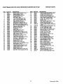
2200 PSI HIGH PRESSURE
WASHER
DESCRIPTION
ITEM
6.5 HP Engine with 70mm piston
(1 req.)
3.0 Gpm Pump (1 req.)
Quick-connect, Male (1 req.)
Quick-connect, Female (1 req.)
Piston Pivot Shoe (3 req.)
O-ring, 2.6 x 114 (1 req.)
Rolling Thrust Bearing (1 req.)
8ram Axial Cam (1 req.)
Engine Adaptor Shaft (1 req.)
M6 Ribbed Lock Washer (6 req.)
Front Gun Bracket (1 req.)
Bal! Thrust Bearing (1 req.)
5/16"-24 x 1" Bolt (4 req.)
Engine Adaptor (1 req.)
Engine Adaptor Gasket (1 req.)
M8 Ribbed Lock Washer (4 req.)
M6-I,0 x 20mm Capscrew (4 req,)
M8-1.25 x 35mm Capscrew (4 req.)
Mounting Base (1 req.)
1/2" Dia. Push Nut (2 req.)
2-1/4" x 4" Wheel (2 req,)
M12 Flat Washer (2 req.)
Jam Nut (2 req.)
Axle Pin (2 req.)
M8-t.25 x 20mm Capscrew (6 req.)
M8-I.25 Flange Nut (12 req.)
5/8" Lock Washer (2 req.)
Support Leg (2 req.)
Shock Mount (2 req,)
M8-1.25 x 40mm Screw (2 req.)
M8 x 25 Flat Washer (2 req,)
Guide Handle (1 req.)
Vinyl Cap (1 req,)
Gun And Hose Holder (1 req.)
5mm x 20mm Flat Washer (2 req.)
#10 Self-drilling Screw (2 req.)
21
37
38
39
40
41
44
45
46
47
48
49
50
51
52
53
54
55
56
57
59
60
61
62
63
64
65
67
66
69
70
72
73
74
75
76
77
78
580.751651
PART NO.
77584
96168
95567A
91630
95567
94197
65852
952!4
96002
95001
95963
90878
45764
77395
96193
46031C
30340
90300
90299
92535
40976
89476
89712
83083
88688
83512
93887
94738
94994
95454
40945
93873
96581E
93723
92661
51767
95441
,
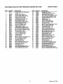
REPAIR
PARTS
DESCRIPTION
Handle Grip(1 req.)
ChemicalInjector Hose (1 req.)
Adjustable Nozzle (1 req.)
3/8" x 25 Ft, Hose Assembly (1 req.)
Gun And Wand Assembly (1 req.)
Pressure Gauge [optional] (I req,)
SpringClip (1 req.)
Cradle (I req,)
Tank Bushing (4 req.)
M6-1.0 x 21mm Bolt (4req,)
Front Gun Bracket (1 req,)
Fual Cap (1 req.)
M4-0.7 x 8mm Taptite Screw(3 req.)
M6-1.0 Locking Nut (2 req.)
Fuel Shut-offValve (1 req.)
Hose Clamp (4 req.)
1/4" I.D. Fuel Hose (1 req,)
Muffler SupportBracket (1 req,)
M5 x 10ram Screw (11 req.)
Muffler SupportBracket(1 req.)
M8 x 20ram Screw (2 req.)
Exhaust Gasket (1 req,)
Muffler Guard(1 req.)
Spark ArrestorScreen (1 req,)
MufflerAssembly(1 req.)
M8-1,25 x 15ram Screw(2 req.)
M16x 1,5 Jam Nut (1 req.)
Bellvitle Washer (1 req,)
Fuel Tank (t req.)
Oil Cap/breather(t req.)
M6-1.0 x 20ram Capscrew(3 req.)
M6 RibbedLockWasher (3 req,)
UntoaderAssembly(1 req.)
SpindleSeat "C1'Ring (I req,)
Nozzle [mv Blue](t req,)
M6 x 1 x 45ram Capscrew (2 req.)
SLEEVE, ENGINE ADAPTOR (1 req.)
Drawing No. 97022
!
I
I
).
Z
8
"0
U)
I
2:
I
m,m
Q
-r
"0
:o
m
U)
U)
C:
:0
m
L
t-a
t,J
:E
I
U)
2:
m
:0
I
I
I
I
I
<
<
Ul
O)
¢n
._L
I
=0
m
4
:o
"13
2J
-4
U)
CRAFTSMAN
ITEM
1
2
3
5
6
7
8
9
10
11
12
13
t4
15
16
17
18
19
20
2!
22
23
24
25
26
27
28
29
30
31
32
33
34
35
38
37
38
39
PART NO.
93871
96430-A
93869
95165
96865
96542
93790
95386
95217
96400
92479
93873
40945
94404
93680
93868
93667
96015
95454
95895
96053
95504
95503
96005
95896
23707
93652
95416
94402
93673
93878
93645
93844
95320
95138
95382
93722
93874
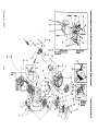
2200 PSi HIGH PRESSURE
WASHER
DESCRIPTION
Engine Adaptor Gasket (1 req.)
Engine Adaptor (1 req.)
Thrust Ball Seating (1 req.)
Engine Adaptor (1 req.)
/_al Cam (1 req,)
Thrust Roller Bearing (1 req.)
! 14 x 119 x 2.60-dng (1 req,)
Piston Spring Retainer (3 req.)
Piston, D15 S.S. (3 req.)
Piston Return Spring (3 req.)
M8 Ribbed Lock Washer (10 req.)
M6 Ribbed Lock Washer (9 req,)
M6 x 1,0 x 20ram Capscrew (7 req.)
Aluminun Crankcase (1 req,)
Pistion Oil Seal (3 mq.)
Pilot Spacer (3 req.)
Seal (3 req.)
Beadng Ring Seal (3 req_)
Oil Fill/Breather (1 req.)
High Pressure Port Tower (3 req.)
High Pressure Seal [black] (3 req.)
Back-up Ring (1 req.)
O-Ring 2.62 x 17.t2mm (6 req.)
Valve Check Kit (6 req.)
Check Valve Seat Support (3 req.)
5/16"-24 x t" Bolt (4 req,)
Thermal By-pass Spring (I req.)
By-pass Piston (1 req.)
Spacer Plate (1 req.)
O-ring 4.5 x 8 x 1.8 (2 req.)
M5-0.8 x 20 Truss Head Bolt (2 req.)
Head Gasket (1 req.)
Thermal By-pass Actuator (t req.)
Garden Hose Connector (1 req.)
sl:CYliinder
Head (1 req.)
ndle Seat (1 req.)
O-Ring, 0.68 X 0.81 x 0.06 (2 req.)
M8_1.25 x 75mm Capscrew (6 req.)
ITEM
580.751651
PART NO.
40
41
42
43
44
45
46
47
48
49
50
51
95373
95367
95372
95378
95377
93788
93787
95-376
95374
95375
95384
95364-B
52
53
54
55
56
57
58
59
60
61
62
63
64
65
66
67
68
69
71
72
73
74
75
76
77
78
95381-B
96137
93723
95216
95369
95368
95370
95363
96069
95506
95453
57163
95371
95380
94738
93887
95386
95441
94944
94284
93876
95379
93656
93657
95212-B
51767
23
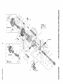
REPAIR
PARTS
DESCRIPTION
UnloaderAssemblySpindle (1 req.)
UnloaderPistonGuide (1 req,)
O-ring 1.78 x 14ram (1 req.)
ChemicalInjector Fitting(1 req.)
HighPressureOutletAdaptor (1 req.)
O-dng 1.78 x 12Atom (1 req.)
O-ring 1.78 x 15.6mm (1 req.)
Spring(1 req,)
High Pressure Outlet Piston (t req,)
O-ring. #2,4 x 4.3 (1 req,)
Pressure Adjust Spring(1 req,)
Pressure Adjust Adaptor with groove
(1 reqj
Pressure Adjust Handle [red] (1 req,)
1/8" NPT Pipe Plug (1 req.)
"O" Ring 2_6x 20.2 (! req.)
Pressure Retief Valve Body (t req,)
Back-up O-ring 11 x 12,4 (1 req.)
Unloader Piston (t req.)
O-ring 1.78 x 7,65 (1 req,)
Spring Support(1 req.)
Quad-Ring 0,09 x 1°06" (3 req_)
Back-up Ring (3 req.)
Sight Gauge Assembly
3/8" NPT Magnetic Plug (1 req.)
Piston SupportO-ring (1 req,)
Chemical Injector Spdng (1 req.)
Belleville Washer (1 req,)
M16-1,6 JAM Nut(t req.)
M18 x 1,0 Nut (1 req,)
Engine Adaptor Sleeve (1 req,)
Piston Pivot Shoe (3 req.)
"C" Ring Retainer(3 req.)
O-Ring, 0.t2 x 0_25x 0.6 (1 req.)
Ball(1 req.)
O-Ring t.78 x 6.07 (1 rsq.)
Back-upRing 1.24 x 6.7 (1 req.)
UnloaderAssembly(1 req.)
M6-1.0 x 45ram Capscrew(2 req.)
Drawing No. 97020
!
LT. aREEN
43
4_
61
BLACK'
IGNITION
SYSTEM
VvlTH LOW OIL 8HUT-DOWN
(LOS) MODULE
32
36
58
TO "C"
7
-4
m
REPAIR
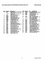
CRAFTSMAN
M
^
,,
_,
o
2200 PSi HIGHPRESSURE
PART NO.
-rv4aoT
,, ....
_4_TK
_._
;;_, o
_-_.
WASHER
580.751651
ITEM
PART NO,
tvwheelAssemblyuse,aw,u,
F"*,,n It r_ '_
I.... _....
f_nltion
Cell ._ssembly (1 req.)
I_16-1.5 Hex Nut !1 re_.)
Cor_ca|Washer (1 req4
_l,_w_r Houstr_ (1 reqj
.
,..
_
35
an_3
"_';..
72u4r
-_=
_
o.....
45756
_J,76
DESCRIPTION
PARTS
QTY.
DESCRIPTION
...........
8
9
10
1!
_o_
91._
78608A
78601
_"l,_k_
Manifold(1 re(t,)
Air Cleaner Cover(1 req.)
r
AirF ilterEtemant(I eq.)
ir Filter pro-cleaner (1 req.)
,.^
13
_,,
15
01b
83
_,....
90051
,,u
_=
.,v
47
16
17
t8
I9
918R_
_
.....
90947
82774
n_u_,
v_
•
ecoil Assembly(1/eq.)
.
R anlfold/He_dGas
.
Ket (1 reqJ
M
. Cleaner Gasker (t req)
Carbumtor/A_r
"
Bolt.- AirCleaner Cover (2 req.>
BreatherHose (1 req.)
av
WoodruffKey (1 req.)
_'.x,19m_nrever Ass <1reqJ
_'l
,,_
_o
_
_o
_t._p.4
_-_'-_
_,_,_
_T_
_real_ar _ar_, .... ....
oPt2y C SParKPlug
....
[Champion[{:l req.)
.
iv16-1.0x 10ramBolt(5 _.R_..},,re" \
M6-10 x 12ramUapscrewu • ,4_
with lock washer _zreq.i
=_
83504
82981
7 653
No 8 x 3/8" Plastlte_:;crew.u ,':'_',
Choke Lever Knob (1 req,}
Bolt(2 req.)
M6-1,0 x 30mm Taptlte
1 re
Shut-offSwlt._.(
_q.)
_
°'51
'_._
.....
22097
512
83
85272
77667
84195
R._.q53
_;_._
"
M6 LockWasher.(.1recl;_,, ._,, \
M8 x 15mm/a Pdie me, u ,,_H.,
Low Od• IndicatorLED(1
. req)
4psi Oil .Pressure.Sw'tch11req.)
LOS Engine Decal (1 req.I
CarburetorWear Washer (1 req.)
Oil Filter Pad GasKetO req._.
¢=,,_,=morAd|Usting_crew (,I
req4
_'_
_?OglA
LOS Module LOPl_pr_),l
',__,_'_.
G0vemor Rod (1 req.)
.
G0v. AdjustBracket(1 req.),
CarburetorMtr_l. Bolt(2 req./
M5-08 Lock Nut (1 req,)
-69
"_0
66311
498! 1
95213
JAMpMS-125 Flex..... _. _H.m,_ \
M6-12.50_DtP)a_,_
__" '_"
Fuel Tank _ra_u, U "_H"
40
43
25
\
Drawing No, 97024
CRAFTSMAN
200
PSI HIGH PRESSURE
WASHER580.751651
27
48
PARTS
14
13
/
3O
REPAIR
51
5
54
19
37
53
31
43
12
44
46
13
39
40
17
ITEM
1
2
3
5
6
7
8
9
10
11
12
13
14
15
16
17
18
19
21
22
23
24
25
26
27
28
PART NO.
7638O
76389
78660
72683
90325
76390
83337
78658
76354
89213B
76349
81695
76359
78645
76365
78699B
83335
89096
88058
78691
76367
76362
78692
78606
76361
89230
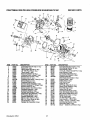
Drawing No. 97021
DESCRIPTION
ITEM
ConnectingRod withCap (1 req,)
29
PistonPin (1 req.)
30
70turnPistonRing Set (1 req.)
31
1/8" NPT Pipe Plug (1 req.)
32
70ramPiston(1 req,)
33
PistonPin Retainer (2 req.)
34
CrankshaftAssrn.w/gear (1 req,)
35
GovernorArm "R" Pin (1 req.)
36
GovernorArm (1 req,)
CrankcaseSub-assrn,[70rnnm](1
req.) 37
Sleeve Bearing(1 req.)
38
CrankshaftSeal (2 req.)
39
GovernorGear Assembly(1 re(].)
40
GovernorRetainer["C" Ring](1 req.)
41
Govemor Spool (1 req.)
42
Sleeve Dowel[12rnm Dia.] (3 req.)
43
CamshaftAssembly(1 req,)
44
CrankcaseGasket (1 req.)
45
Cylinder Head Gasket (1 req.)
46
47
Oi| PressureSprg R_ainer (1 req.)
Oil PressureSpring(1 req.)
48
PressureReliefBall (1 req.)
49
M5-03 x 8rnrnScrew (1 req.)
50
M6-1,0x 12rnmScrew (4 req,)
51
Thrust Washer (1 req,)
52
FlangedHex Capscrew(6 req.)
53
54
57
26
PART NO.
88420A
86293
88401
88590
83152
76381
78659
88404B
90082
90081
88396A
83235
80336
88397
77161
77160
76307
88403
77168
88412
76329
72657
83153
86254
84186
88156
82773J
50
57
DESCRIPTION
Sub-assernblyGear Cover (1 req.)
Valve SpringRetainer (2 req.)
Valve Spring(2 req.)
12ramdia. x 20turnDowel Pin (1 req.)
Inner Gerotor(1 req.)
ConnectingRod Bolt(2 req,)
GovernorArmWasher (1 req.)
CylinderHead with
Valve Seats and Guides (1 req,)
ExhaustValve (1 req.)
Intake Valve (1 req,)
Push Rod (2 req,)
Tappet (2 req.)
Oil PickupASsembly(1 reqJ
Rocker CoverGasket (t req.)
Pivot Ball Stud (2 req.)
Rocker Arm (2 req,)
Jam Nut [rockerArm] (2 req.)
Push Rod Guide Plate (1 req.)
M8 x 52ram Head Bolt(5 req.)
RockerCover Assm. (1 req.)
Oif Fill Plug(2 req,)
1/4" NPT Pipe Plug (1 req.)
Outer Gerotor-- 6/5 (1 req.)
O-dng - 17.8 I.d. x 2.4rnrn(1 req.)
Valve SpringWasher (2 req:)
Valve Stern Seal (1 req.)
Decal -- Serial No, [70mm] (1 req,)
CRAFTSMAN
2200 PSi HIGH PRESSURE
WASHER
580.751651
REPAIR
PARTS
4 3
4
3
4
ITEM
1
2
3
4
5
6
9
10
!1
I2
13
PART NO,
100-81671
105-81671
103-81671
104.81671
t O9-81671
106-81671
102-81671
10t-81671
108-81671
107-81671
DESCRIPTION
REWIND STARTER HOUSING(1 REQ.)
BRAKE SPRtNG(t REQ.)
DOG SPRING(2 REQ,)
STARTER DOG(2 REQ,)
RETAINER PAWL(1REQ.)
RETAINER PAWL SCREW(1REQ.)
PULLEY(1 REQ.)
SPRING AND KEEPER(1 REQ.)
HANDLE INSERT(1 REQ.)
STARTER ROPE WITH HANDLE(IREQ.)
ROPE (INCLUDED WITH ITEM 12)(1 REQ.)
Drawing No. 97020
FULL ONE YEAR WARRANTY
ON CRAFTSMAN
HIGH PRESSURE
WASHER
For one year from the date of purchase, when this Craftsman High Pressure Washer is maintained and operated
according to the instructions in the owner's manual, Sears wiii repair, free of charge, any defect in material and
workmanship.
tf this washer is used for commercial purposes, this warranty applies for only 90 days from the date of purchase.
If this high pressure washer is used for renta! purposes, this warranty applies for only 30 days after date of
purchase.
FULL TWO YEAR WARRANTY
ON CRAFTSMAN
ENGINE
For two years from the date of purchase, when this Crafstman engine is maintained and operated according to
the instructions in the owner's manual, Sears will repair, free of charge, any defect in material and workmanship.
If the Craftsman Engine is used for commercial or rental purposes, this warranty applies for only one year from
the date of purchase,
This warranty does not cover:
•
Expendable items such as spark plugs and air filters, which become wom during normal use.
*
Repairs necessary because of operator abuse or negligence, including damage resulting from no water being
supplied to pump or failure to maintain the equipment according to the instructions contained in the owner's
manual.
WARRANTY SERVICE IS AVAILABLE BY RETURNING THE HIGH PRESSURE WASHER TO THE NEAREST
SEARS SERVICE CENTER/DEPARTMENT THROUGHOUT THE UNITED STATES.
This warranty gives you specific legal rights and you may also have other rights, which vary from state to state.
SEARS, ROEBUCK AND CO., D/817 WA, Hoffman Estates, IL 60179
27
CRRFTSMRN°
6.5 HORSEPOWER
OWNER'S
MANUAL
2200 PSI
3 GPM
HIGH PRESSURE
WASHER
Each High Pressure Washer has its own model number. Each engine has
its own part number. Each engine has its own model number.
MODEL NO.
580.751651
The model number for your pressure washer will be found on a decal
attached to the unit.
The part number for your engine will be found in the parts list.
All parts listed herein may be ordered through Seam, Roebuck and Co.
Service Centers and most Retail Stores.
IF YOU NEED
REPAIR SERVICE
WHEN ORDERING
REPAIR
LOWING
INFORMATION:
OR PARTS
•
FOR REPAIR SERVICE CALL
THIS TOLL FREE NUMBER
1-800-4,REPAIR
(1-800-473-7247)
PRODUCT_HIGH
PARTS,
ALWAYS
PRESSURE
•
MODEL
NUMBER--
•
PART
NUMBER
•
PART
DESCRIPTION
GIVE
THE FOL-
WASHER
580.751651
FOR REPLACEMENT PARTS
INFORMATION AND ORDERING,
CALL THIS TOLL FREE NUMBER:
Your Sears merchandise has added value when you consider that Sears
has service units nationwide staffed with Sears trained technicians....professional technicians specifically trained on Sears products, having the
parts, tools and the equipment to ensure that we meet our pledge to you,
we service what we sell.
1-800-FON-PART
(1-800-366-7278)
,ll ,I,I,L
SEARS,
,
ROEBUCK
mL.,lll,,ll,
and
CO.,
Hoffman
,,i,l,,ll ,i,l,ll,
Estates,
IL
60179
,,,,,i,, i ii
U.S.A.
,f
Part No. 97016 Revision 4 (11/14/95)
Primed in U,S.A,