1
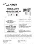
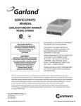
INSTALLATION, OPERATION AND REPAIR MANUAL
GAS SKILLET
MODEL #
SGL-T
SGM-T
SE95001
CLEVELAND RANGE INC
1333 East 179th St.
Cleveland, Ohio
U.S.A. 44110
(216) 481-4900
9111 REV:0
- -IF YOU SMELL GAS - -
FOR YOUR SAFETY
1. OPEN WINDOWS.
2. DO NOT TOUCH ELECTRICAL
SWITCHES.
3. EXTINGUISH ANY OPEN
FLAME.
4. CALL YOUR GAS SUPPLIER
IMMEDIATELY.
DO NOT STORE OR USE
GASOLINE OR ANY OTHER
FLAMMABLE LIQUIDS AND
VAPOURS IN THE VICINITY
OF THIS OR ANY OTHER
APPLIANCE.
IMPORTANT
THE FOLLOWING POINTS ARE TO ENSURE THE SAFE INSTALLATION AND OPERATION OF THIS
EQUIPMENT :
ENSURE ALL GAS AND ELECTRICAL SUPPLIES MATCH RATING PLATE AND ELECTRICAL
STICKERS
OBSERVE ALL CLEARANCE REQUIREMENTS
DISCONNECT THE ELECTRICAL POWER SUPPLY TO THE APPLIANCE BEFORE CLEANING OR
SERVICING UNIT
ONLY A QUALIFIED SERVICE TECHNICIAN SHOULD REPAIR UNIT
THE INSTALLATION AND CONNECTION MUST COMPLY WITH LOCAL CODES, OR IN THE ABSENCE
OF LOCAL CODES, WITH CAN1 B149 INSTALLATION CODE OR WITH THE NATIONAL FUEL GAS
CODE, ANSI Z223.1-1988.
POST IN A PROMINENT LOCATION, INSTRUCTIONS TO BE FOLLOWED IN THE EVENT THE USER
SMELLS GAS. THIS INFORMATION SHALL BE OBTAINED BY CONSULTING YOUR LOCAL GAS
SUPPLIER.
THE APPLIANCE AND ITS INDIVIDUAL SHUT OFF VALVE MUST BE DISCONNECTED FROM THE GAS
SUPPLY PIPING SYSTEM DURING ANY PRESSURE TESTING OF THAT SYSTEM AT TEST PRESSURES
IN EXCESS OF 1/2 PSIG. (3.45 KPA).
THE APPLIANCE MUST BE ISOLATED FROM THE GAS SUPPLY PIPING SYSTEM BY CLOSING ITS
INDIVIDUAL MANUAL SHUT OFF VALVE DURING ANY PRESSURE TESTING OF THE GAS SUPPLY
PIPING SYSTEM AT TEST PRESSURES EQUAL TO OR LESS THAN 1/2 PSIG. (3.45 KPA).
RETAIN THIS MANUAL FOR YOUR REFERENCE.
1
422-01TE
GENERAL INFORMATION
regulator which is installed on the manifold. For
easy access to the pressure regulator, view along
left side of unit from underneath.
The serial plate is located on the left hand box cover.
Remove front lift off cover for access. Gas type,
burner ratings and electrical requirements are stated on
the plate.
Once pressure test is completed, turn power
switch and thermostat to the "OFF" position and
replace control box cover using self tapping
screws removed earlier.
1. Damage check: always check carton or crate for
possible damage incurred in shipping. After
carefully uncrating, check for "concealed"
damage. Report any damage immediately to your
carrier.
5. Have a qualified gas technician check the gas
pressure to make certain that existing gas
facilities (meter, piping, etc.) will deliver the
BTU's of gas required at the unit with no more
2. 208/240 volt units are equipped with a circuit
breaker. Should it be necessary to reset the
breaker, the reset button is located in the center of
the right control box. Remove front panel for easy
access.
than 1/2" water column pressure drop. When
checking pressure, be certain that all the
equipment on the same gas line is turned to the
"ON" Position
3. The correct type of gas for which the unit was
manufactured is noted on the rating plate, and this
type of gas must be used.
4.
6. Make certain that new piping joints and
connections have been made in a clean manner
and have been purged, so that piping compound,
chips, etc., will not clog pilots, valves, and/or
controls. Use pipe joint sealant that is approved
for use with liquefied petroleum gas.
A pressure tap is supplied with the unit just before
the pilot solenoid valve which is installed on the
manifold. The gas pressure must be checked when
unit is installed, to ensure unit gas pressure is the
same as specified on rating plate. For access to the
pressure tap, remove front panel, turn power
switch to the "OFF" position as a precaution, and
remove the two self tapping screws which secure
the left control box cover. Turn power switch and
thermostat to the "ON" position (using extreme
caution) and complete pressure test.
7.
WARNING: Always check gas connections for
leaks using soap solution or like means. DO
NOT CHECK WITH OPEN FLAME.
INSTALLATION CLEARANCES
This unit must be installed in accordance with the
following clearances in order to provide proper
operation and servicing of the appliance. Also, it is
recommended that unit be installed with sufficient
clearances to provide for proper cleaning and
maintenance. Minimum clearances are 1" for the
sides and 6" from back.
If necessary, pressure adjustments can be made at
the pressure
2
422-02TE
INSTALLATION
For ease in attaching the supply lines there is a
removable cover on the electrical housing. Feed wire
through hole in the center of the electrical housing and
attach to the terminal block.
1. Carefully remove unit from carton or crate.
Remove any packing material from unit. On
stainless steel panels, the protective material
should be removed before the unit is installed.
IMPORTANT: This appliance must be electrically
grounded in full accordance with local codes, or in the
absence of local codes, with the Canadian Electrical
Code C22.1 or with the National Electrical Code,
ANSI/NFPA No. 70-1990 (whichever is applicable).
2. Set skillet in position where gas and electrical
services are nearby. Comply with clearances
stated on the specification sheet. Ensure there is
sufficient clearance between fry pan and back
wall Check for overhead clearance to
accommodate for hinged cover when in the
raised position.
3.
GAS CONNECTION
Level skillet by means of adjustable stainless steel
feet Use a spirit level and level unit four ways;
across front, back, and down left and right edges.
Securely anchor the adjustable feet to the floor
and seal joints with a silicone sealant
It is recommended that a sediment trap (drip leg) be
installed in the gas supply line. If the gas pressure
exceeds 14" water column, a pressure regulator must
be installed, to provide a maximum of 14" water
column gas pressure to the gas control valve.
4. FOR YOUR SAFETY: Keep the appliance area
free and clear of any combustible materials.
Connect the gas supply piping to the input side of the
gas control valve. Location and pressure data are
shown on the specification sheet. Installation must be
in accordance with local codes and/or the National
Fuel Gas Code ANSI Z223.1-1988 (USA) or
Installation Codes for Gas Burning Appliances and
Equipment CANI B149.1 and B149.2 (Canada). Use a
gas pipe joint compound which is resistant to L.P. gas.
Test all pipe joints for leaks with soap and water
solution. Ensure that the gas pressure regulator is set
for the manifold pressure indicated on the gas rating
plate.
ELECTRICAL CONNECTION
A direct electrical connection is required at the
terminal block located near the front side of unit. The
supply line will enter through the rear (or bottom) of
the skillet. Refer to specification sheet for the exact
locations.
3
422-03TE
VENTILATION
4.
A gas skillet must be installed in a location in which the
facilities for ventilation permit satisfactory combustion
of gas and proper venting. Proper ventilation is
imperative for good operation of the appliance. The
ideal method of ventilating a gas skillet is the use of a
properly designed ventilating canopy, which should
extend at least 6" (152mm) beyond all sides of the
appliance (except against a wall, if the canopy is a wall
installation). This is usually part of a mechanical
exhaust system.
Do not permit fans to blow directly at the
appliance, and wherever possible, avoid open
windows adjacent to the appliance sides and back;
also wall type fans which create air cross-currents
within the room.
START UP PROCEDURE
This appliance has been factory tested and adjusted
under ideal conditions but, rough handling, low gas
pressure, altitude or variations in gas characteristics
may require fine adjustment.
Further information can be obtained by referring to the
U.S.A. National Fire Protection Associations NFPA96
regulations. These standards have also been adopted by
the National Building Code in Canada
All units are equipped with fixed orifices and do not
require primary air adjustment
LIGHTING INSTRUCTIONS
AIR SUPPLY
Ensure gas and electrical supply to the appliance, are
in the "ON" position. Note:
On initial light up, air must be purged from the line to
achieve pilot ignition. To light pilot, proceed as
follows:
1. Turn power switch to the "ON" position.
1. It is necessary that sufficient room air ingress be
allowed to compensate for the amount of air
removed by any ventilating system. Otherwise, a
subnormal atmospheric pressure will occur,
affecting the appliance operation adversely and
causing undesirable working conditions.
2. Wait one minute to allow flame sensor to heat up.
2. Appliances shall be located so as not to interfere
with proper circulation of air within the confined
space. All gas burners and pilots require sufficient
air to operate.
3. Turn thermostat to the required temperature.
4. To shut down, turn thermostat and power switch
off.
3. Large objects should not be placed in front of the
appliance which might obstruct the air flow
through the front Do not obstruct the flow of
combustion and ventilation air.
NOTE: If pilot is out, mm power switch to the "OFF"
position. A 5 minute shut off period is required before
relighting.
If pilot does not continue to burn after repeating the
lighting instructions, mm power to the "OFF" position
and have a qualified serviceman check the system.
4
422-04TE
7. If desired, once product has cooked, it can be
held prior to serving at a lower temperature
setting.
OPERATING INSTRUCTIONS
1. Ensure gas and electrical supply to the appliance
are in the "ON" position.
8. When cooking is completed, set thermostat and
power switch to the "OFF" position.
2. Turn power switch to the "ON" position. Pilot
light will indicate power is on. Wait one minute
to allow flame sensor to heat up.
9.
3. Cleveland skillets are equipped with an electrical
power tilt mechanism for ease in raising and
lowering the skillet
FOR YOUR SAFETY, this skillet is also equipped
with a power interrupter which automatically shuts off
the gas supply to the burners whenever the skillet is
raised more than 1/2" (13mm). When released, the tilt
mechanism will stop gently at any point and has a slip
clutch overload protector.
OPERATING SUGGESTIONS
1. Turn power switch to the "OFF position when
skillet is not in use.
IMPORTANT: Before commencing to cook, ensure
skillet is in the lowered position by pressing down on
the tilt switch. Ensure cover is raised first
4. To preheat, set thermostat to desired cooking
temperature. Pilot light will cycle on and off
with the thermostat. In the event of a high heat
condition (over 450* F), the red pilot light will
flash to alert the operator and the gas supply to
the main burners will automatically shut off.
5.
The best time to dean the skillet is immediately
after use, once skillet has cooled down. Refer to
the section titled CLEANING
INSTRUCTIONS.
2.
Clean skillet as soon as possible after cooking.
3.
Allow skillet to preheat before adding product.
4.
Always lift the hinge assist before activating the
tilt switch.
MAINTENANCE INSTRUCTIONS
You have purchased the finest commercial cooking
equipment available anywhere. Like any other fine
precision built piece of equipment it should be given
regular care and maintenance.
Allow skillet to preheat for approximately 15-30
minutes.
Periodical inspections by your dealer or a qualified
service agency are recommended to check
temperatures, adjustments and ensure moving parts
are operative. Whenever possible, avoid overheating
idle equipment as this is the primary cause for
increased service costs.
6. Once preheated, insert product in skillet and
adjust thermostat to required cooking
temperature.
5
422-05TE
When corresponding with the factory or your
equipment dealer regarding service problems or
replacement parts, be sure to refer to the particular unit
by the correct model number (including prefix and
suffix letters and numbers) and the serial or code
number. The rating plate affixed to the unit contains
this information.
Do not use grill stones. Heat tint can be removed
by a vigorous scouring in the direction of the
polish lines using SCOTCH-BRITE scouring
pads or a STAINLESS scouring pad in
combination with a non abrasive powdered
cleanser.
4. Tomato and vinegar based products have a high
add content which could attack the stainless steel
finish of the skillet After cooking of such
products, clean skillet interior with a baking soda
and water solution. Use one tablespoon baking
soda per 1 gallon of water.
"REGULAR MAINTENANCE ENSURES
PEAK PERFORMANCE."
CLEANING INSTRUCTIONS
5. After cleaning, the skillet should be thoroughly
rinsed with clean water and dried.
A regular daily cleaning program should be followed to
maintain your skillet's efficient performance and
minimize service calls. At the end of each day's
operation, the following steps are recommended:
PILOT BURNER ADJUSTMENT
1. Turn power switch to the "OFF" position.
1. Ensure power switch is in the "ON" position.
2. Skillet should be cleaned after each use, as soon as
possible after cooking.
2.
3. For general purpose cleaning, use a soft cloth with
mild detergent and warm water. A sponge, nonabrasive scouring pad or a fiber brush can also be
used for this purpose.
To remove grease that has baked on, apply a nonabrasive cleanser to a damp cloth or sponge and
rub cleanser on the metal in the direction of the
polishing lines of the metal. NEVER RUB IN A
CIRCULAR MOTION. Soil or burnt deposits
which do not respond can usually be removed by
rubbing the surface with SCOTCH-BRITE
scouring pads or STAINLESS scouring pads. DO
NOT USE ORDINARY STEEL WOOL.
Raise skillet high enough to observe the pilot
burner flame.
3. Remove front panel
4. Turn power switch to the "OFF" position as a
precaution. Remove the two self tapping screws
which secure the left control box cover.
5. Turn power switch to the "ON" position in order to
energize the pilot
6. Once pilot is lit turn pilot adjusting screw (located
downstream of the pilot solenoid valve) clockwise
to decrease or counter-clockwise to increase until a
1" (25mm) flame is obtained.
7.
Re-install control box cover removed in step 4.
6
422-06TE
CLEVELAND SKILLETS
GAS TILTING OPEN
BASE AND MODULAR
SKILLETS
MODELS:
_ SGL-30-T
_ SGL-40-T
General Specifications:
• Leg or modular base
• Pull 40 gallon capacity rating to bottom of pouring lip
• Power tilt
• Stainless steel clad 5/8" cooking surface guaranteed
against warping
• Stainless steel coved cornered pan with both gallon and
liter markings
• Space saving design - no clearance required at rear or
sides (optional faucet and console requires 4" on one
side)
• All stainless steel construction for durability and easy
cleaning
• Adjustable, thermostat controls temperature from 100°F
to 425°F
• High efficiency heating system with even heat
distribution
• Fast heat-up and recovery time - preheats in 15
minutes, full capacity from cold to boiling in 60 minutes
• Spring assist cover with adjustable vent and full width
handle
• On/off switch, thermostat knob and pilots recessed to
avoid breakage
• Four stainless steel, level-adjustable feet, rear
flanged for bolting
• A.G.A., CGA, UL, CSA and NSF approved
• Serviceable from the front
• Three pilot lights, green-power on, ambertemperature cycling, red-flash to indicate heal
conditions
_ SGM-30-T
_ SGM-40-T
MODELS AVAILABLE
Model No.
Description
SGL-30-T
30 gallons /115 liters, Gas, Tilting, Open
Base
SGL-40-T
40 gallons / 150 liters, Gas, Tilting, Open
Base
SGM-30-T
30 gallons / 115 liters, Gas, Tilting,
Modular Cabinet Base
40 gallons / 150 liters, Gas, Tilting,
Modular Cabinet Base
SGM-40-T
Options and Accessories:
‘ Hydraulic hand tilt with quick lowering feature (HTS)
‘ Console mounted H/C water faucet (CMFS)
‘
‘
‘
‘
‘
Pan carrier (PCS)
Poaching Pans (PP)
Vegetable steamers (VS)
Wall mounting (WMS)
In-wall carrier (IWCS)
‘ 2" butterfly valve c/w fittings to adapt to metering
filling stations (BVS-2)
‘ Electronic spark ignition (ESS)
‘ Double or single pantry skillet filler with 60" long
hose (SKF-S or DKF-S)
‘ Hot and cold pre-rinse spray head with hose (PRS-S)
‘ Gas types other than natural
‘ Voltage and wiring other than standard
‘ Food strainer for pouring spout
CLEVELAND RANGE, INC.
1333 East 179th St., Cleveland, Ohio 44110
Telex: 98-0546 -Facsimile: 216-481-3782
7
422-07TE
SHORT FORM SPECIFICATION
Shall be CLEVELAND, Tilting Skillet Model SG_-__-T
gas (Type ___) holding no less than ___ gallons;
complete with thermostatic safety and gas controls;
gallon markings; stainless steel dad 5/8" cooking
surface; power tilt; spring assist cover with adjustable
vent. All stainless steel construction; no clearances
required.
8
• CAPACITIES: (in 4 oz. servings) (Other sees may be
calculated)
30 Gallons /115 liters… 960
40 Gallons /150 liters… 1280
• Many local codes exist and it is the responsibility of the
Owner and Installer to comply with those codes.
• Cleveland equipment is built to comply with applicable
standards for manufacturers. Included among those
approval agencies are: UL, A.G.A., NSF, ASME/N-Bd.,
CSA, CGA, ETL, and others.
422-07TD
MODEL SGL - T, SGM - T
OPERATING CONTROLS & INDICATORS
For your better understanding and confidence, the following explanation of the control system used on
these skillets is offered.
ITEM NO.
DESCRIPTION
FUNCTION
3
Switch, ON-OFF
( Pg. 422-08TD )
ON-OFF power switch for unit.
2
Pilot light, green
Light is on as long as power
switch is on.
( Pg. 422-08TD )
4
Lamp, flashing, red
( Pg. 422-08TD )
5
6
Pilot light, amber
Indicates there is a problem and
burners have been shut down.
( Pg. 422-08TD )
Light is on when burners are
ON.
Tilt switch
Tilts pan up or down-
( Pg. 422-08TD )
3
Hand wheel
( Pg. 422-16TD )
Turn clockwise to raise pan.
1
Lever
( Pg. 422-16TD )
Depress lever to lower pan.
9
422-13TE
PARTS LIST - GAS CONTROL ASSEMBLY
ITEM NO.
1.
12.
13.
14.
15.
16.
17.
18.
19.
PART NO.
078239-1
078239-2
076129-1
076131-01
076132-01
G03056-52F
G03056-57F
G01917-1
G02971-1
G01475-1
G01739-1
G01475-2
G01738-8
2127500
2127503
2127502
G01918-5
G01736-1
G01474-2
G01518-1
076133-1
071703-1-6
G02965-1
076050-80
20.
21.
22.
23.
24.
G6809
G02251-1
076029-144
076029-54
076050-14
25.
26.
077189-1
076029-1
2.
3.
4.
5.
6.
7.
8.
9.
10.
11.
DESCRIPTION
Pilot N.G., 2000 ft.
Pilot Propane, 2000 ft.
Burner
Manifold 30 gal.
Manifold 40 gal.
Orifice #52, N.G., 2000 ft.
Orifice #57, L.P., 2000 ft.
Street elbow 1/8"
Reducer 1/2" to 3/8"
Street elbow 1/2"
Union 1/2"
Street elbow 3/4"
Nipple 3/4" x 1-1/2"
Gas Regulator L.P.
Gas Regulator N.G. 40 gal.
Gas Regulator N.G. 30 gal.
Reducer bushing 3/4" to 1/2"
Closed nipple 1/2" x 1-1/8"
1/2" Elbow
Shut-off valve
Nipple 1/2" x 2.5"
Bracket
Solenoid valve
Compression elbow 1/4" tube to 1/8" pipe
Pilot valve adjustment
Pressure test spigot
Bushing 3/8" to 1/8"
Street tee 1/8"N.
Compression connector
1/4-CC to 1/8"NPT
Flame switch
1/8"NPT closed nipple
10
QTY.
1
7-10
1
7-10
7-10
2
1
2
1
1
1
1
1
1
1
1
1
2
1
1
1
2
1
1
1
1
422-09TEA
GAS CONTROL ASSEMBLY
11
422-09DR
PARTS LIST - BURNER BOX ASSEMBLY
ITEM NO.
PART NO.
DESCRIPTION
QTY.
1.
071715-1-6
Rear mounting bracket
2
2.
071692-5-6
Rear combustion seal, 40 gal.
2
071692-3-6
Rear combustion seal, 30 gal. L.H.,11 1/2"
1
071692-4-6
Rear combustion seal, 30 gal. R.H., 15 1/2"
1
071639-01-6
Rear cover, 40 gal.
1
071638-01-6
Rear cover, 30 gal.
1
4.
071497-1-6
Inside hinge cover
2
5.
071689-5-6
Burner hold down, 40 gal.
2
071689-4-6
Burner hold down, 30 gal. R.H., 12 3/4"
1
071689-3-6
Burner hold down, 30 gal. L.H., 8 3/4"
1
071722-1-6
Burner rest, 40 gal. L.H.
2
071713-1-6
Burner rest, 30 gal. R.H., 13 1/4"
1
071725-1-6
Burner rest, 30 gal. L.H., 9"
1
071721-1-61
Front shield, 40 gal. R.H.
1
071721-1-62
Front shield, 40 gal. L.H.
1
071711-1-6
Front shield, 30 gal. R.H., 14"
1
071724-1-6
Front shield, 30 gal. L.H., 10"
1
071642-1-6
Burner pan, 40 gal.
1
071641-1-6
Burner pan, 30 gal.
1
9.
071714-1-6
Ignitor bracket
1
10.
2148900
Back top support
1
3.
6.
7.
8.
12
422-14TEA
BURNER BOX ASSEMBLY
13
422-14DR
PARTS LIST - SKILLET HINGE ASSEMBLY
ITEM NO.
PART NO.
DESCRIPTION
QTY.
1.
F248
Acorn nut #1/4-20 S.S.
4
2.
F255
Lockwasher #1/4 S.S.
2
3.
F365
Cap screw #1/4-20 x 3/8"
2
4.
2214099
Cover assembly, 30 gal.
1
2214098
Cover assembly, 40 gal.
2214599
Deflector, 30 gal.
2214598
Deflector, 40 gal.
6.
2209300
Knob
3-4
7.
F192
Bolt #1/4-20 x 1/2" S.S.
2
8.
1005800
Spring
2
9.
G2782-2
Hook bolt
2
10.
F76
Locknut #1/4-20
2
11.
2084500
Plate
2
12.
078056-5
Bearing
2
13.
F59
Bolt #1/2-13 x 3/4"
2
14.
078248-1
Spacer
2
15.
G02925-2
Bushing
2
16.
F257
Lockwasher #1/2" S.S.
2
17.
F246
Nut #1/2-13 S.S.
4
18.
F359
Set screw
2
19.
2059600
Strike plate
1
20.
F358
1/2"-13 Hex jam nut
1
5.
1
14
422-15TEA
SKILLET HINGE ASSEMBLY
15
422-15DR
PARTS LIST - HYDRAULIC JACK ASSEMBLY
ITEM NO.
PART NO.
DESCRIPTION
QTY.
1.
F194
Bolt, hex head
2
2.
F258
Lockwasher
2
3.
G03897-1-6
Spacer
1
4.
078208-1M
Mounting bracket
1
5.
2218600
Adapter block
2
6-
1480800
Washer
2
7.
2218500
Mounting pin
1
8.
2219000
Retaining ring
2
9.
2249300
Coupling
2
10.
2249400
Hydraulic tubing
1
11.
2249500
Connector
1
**12.
078246-2
Spring
1
**13.
2251700
Cylinder
1
**14.
2251800
Tie rod
2
**15.
2251900
Cylinder top
1
16.
078247-1
Spring support
1
17.
078194-1
Yoke assembly
1
**18.
F239
Hex nut, 1/4-20
2
**19.
2252000
Cylinder base
1
**20.
2252100
Piston rod
1
**21.
2252200
Spring
1
**22.
2252300
Wiper seal
3
**23.
2252400
Cylinder piston
1
**24.
2252500
Seal
1
**25.
2252600
Plug
1
26.
F255
S/S Split lock washer
2
Bronze bearing
1
27.
078245-1
** Purchased as Assembly CK 112
16
422-10TEA
HYDRAULIC JACK ASSEMBLY
17
422-10DR
PARTS LIST - HYDRAULIC TILT ASSEMBLY
ITEM NO.
PART NO.
DESCRIPTION
QTY.
1.
2249900
Lever
1
2.
3.
4.
5.
6.
7.
8.
9.
10.
11.
12.
13.
2250000
2250100
2251300
2250200
2250300
2250400
2250500
2250699
2250700
2250800
F192
2250900
Set screw #3/8-24 x 3/8" S.S.
Handwheel
Bolt #1/4-20 x 1/2" S.S.
Push rod
Cotter pin
Bracket
Hydraulic pump
Oil tank
Plug
Male connector
Bolt #3/8-24 x 3/4"
Set screw #10-32 x 5/16"
1
1
2
1
2
1
1
1
1
1
2
2
18
422-16TDA
PARTS LIST - ELECTRIC JACK ASSEMBLY
ITEM NO.
PART NO.
DESCRIPTION
QTY.
1.
2.
3.
4.
5.
6.
7.
8.
9.
10.
F194
F258
G03897-1-6
078208-1M
1480800
078192-1
078246-1
078247-1
078194-1
078245-1
Hex head bolt
Lockwasher
Spacer
Mounting bracket
Washer
Actuator
Spring
Spring support
Yoke assembly
Bronze bearing
2
2
1
1
2
1
1
1
1
1
19
422-11TDA
PARTS LIST - ELECTRICAL COMPONENT ASSEMBLY
ITEM NO.
1.
2.
3.
4.
5.
6.
7.
8.
9.
10.
11.
12.
13.
14.
15.
16.
17.
PART NO.
077192-1
G01296-3
G03054-2
G02315-2
G01296-2
2090700
077189-1
077188-1
050069
050070
G01500-1
077200-1
2075700
077190-2
2095600
077145-2
G02716-1
G02725-29
G02725-30
DESCRIPTION
Thermostat
Pilot light, green
Switch, on-off
Lamp, flashing, red
Pilot light, amber
Tilt switch
Switch
Spark ignition module
Terminal block
Terminal end
Ground terminal
High limn
Transformer 120/240/24V, 200VA
Transformer 208-600/120V/24V
Push button switch, momentary
Bridge rectifier
Dial
Dial insert, (100-425° F)
Dial insert, ( 37-220° C)
20
QTY.
1
1
1
1
1
1
1
1
2
1
1
1
1
1
1
1
1
422-08TDA
PARTS LIST - FAUCET
ITEM NO.
1.
2.
3.
4.
5.
PART NO.
2201900
2202000
2202400
2202300
2202200
2202100
DESCRIPTION
Single pantry control valve
Double pantry control valve
"O'' ring
Retaining ring
Spout nut, tall
Faucet spout
21
QTY.
1
1
1
1
1
1
422-17TDA
PARTS LIST - COVER-VENT CAP AND DEFLECTOR
ITEM NO.
1.
2.
3.
4.
5.
6.
7.
8.
9.
PART NO.
2211500
2211400
2211100
2209300
2211300
2211099
2211200
2209301
2214599
2214598
DESCRIPTION
Screw, 1/4-20 x 3/8"
Washer
Support arm
Knob
Spacer
Cover
Spacer
Knob
Deflector assembly (30 gal.)
Deflector assembly (40 gal.)
QTY.
1
1
1
1
1
1
1
3,4*
1
1
* The first figure applies to 30 gal. skillets, the second figure applies to 40 gal. skillets.
22
422-12TDA
PARTS LIST - BODY PARTS (NO DRAWING)
ITEM NO. PART NO.
1.
2212200
2212204
2212205
2212201
2212206
2212202
2212203
2212207
2.
2211701
2211700
3.
078005-03
078160-1
4.
078005-04
078161-1
5.
2251600
6.
2247900
7.
2249800
2249801
DESCRIPTION
Front panel, manual tilt 30 gal., leg base
Front panel, power tilt 30 gal., leg base
Front panel, power tilt 40 gal., leg base
Front panel, manual tilt 40 gal., leg base
Front panel, power tilt 30 gal., modular
Front panel, manual tilt 30 gal., modular
Front panel, manual tilt 40 gal., modular
Front panel, power tilt 40 gal., modular
Side panel, modular base
Side panel, leg base
Leg assembly, hex foot, modular base
Foot assembly, hex foot, leg base
Leg assembly, flange foot, modular base
Foot assembly, flange foot, leg base
Strainer
Pan carrier
Faucet bracket, left band
Faucet bracket, right hand
QTY.
1
2
2
2
23
422-18TEA
WIRING DIAGRAM - 208 / 220 / 240 VOLTS
24
422-19DR
WIRING DIAGRAM - 120 VOLTS
25
422-20DR