1
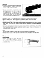
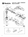
1 2 5 m m ( 5 ” ) MODEL G A S 0 0 0
INSTRUCTION MANUAL
Disc Grinder & Standard Equipment
@ Tool
body
@ Grip
@) Depressed center wheel
Lock nut wrench
Specifications
Continuous
rating
(Input)
No load
speed
850 W
R/min.
Overall
length
I
2 7 8 mm
(11”)
Power
supply cord
Net weight
~
2.5 kg
(5.51bs)
1
2.5 m
(8.2ft.l
,
Spindle
thread
1
5/8-11UNC
~~
Manufacturer reserves the right t o change specifications of parts and accessories without notice.
Note: Specifications of parts and accessories may vary from country t o country.
IMPORTANT SAFETY INSTRUCTIONS
WARNING: When using electric tools, basic safety precautions should always be followed
to reduce the risk of fire, electric shock, and personal injury, including the following:
READ ALL INSTRUCTIONS.
1. KEEP WORK AREA CLEAN. Cluttered areas and benches invite injuries.
2. CONSIDER WORK AREA ENVIRONMENT. Don't use power tools in damp or wet
locations. Keep work area well lit. Don't expose power tools to rain. Don't use tool
in presence of flammable liquids or gases.
3. KEEP CHILDREN AWAY. All visitors should be kept away from work area. Don't
let visitors contact tool or extension cord.
4. STORE IDLE TOOLS. When not in use, tools should be stored in dry, and high or
locked-up place out of reach of children.
5. DON'T FORCE TOOL. It will do the job better and safer at the rate for which it
was intended.
6. USE RIGHT TOOL. Don't force small tool or attachment to do the job of a heavyduty tool. Don't use tool for purpose not intended.
7. DRESS PROPERLY. Don't wear loose clothing or jewelry. They can be caught in
moving parts. Rubber gloves and non-skid footwear are recommended when working
outdoors. Wear protective hair covering to contain long hair.
8. USE SAFETY GLASSES. Also use face or dust mask if cutting operation i s dusty.
9. DON'T ABUSE CORD. Never carry tool by cord or yank it to disconnect from receptacle. Keep cord from heat, oil, and sharp edges.
10. SECURE WORK. Use clamps or a vise to hold work. It's safer than using your hand
and it frees both hands to operate tool.
11. DON'T OVERREACH. Keep proper footing and balance a t all times.
12. MAINTAIN TOOLS WITH CARE. Keep tools sharp and clean for better and safer
performance. Follow instructions for lubricating and charging accessories. Inspect
tool cords periodically and if damaged, have repaired by authorized service facility.
Keep handles dry, clean, and free from oil and grease.
13. DISCONNECT TOOLS. When not in use, before servicing, and when changing accessories, such as blades, bits, cutters.
14. REMOVE ADJUSTING KEYS AND WRENCHES. Form habit of checking to see
that keys and adjusting wrenches are removed from tool before turning it on.
15. AVOID UNINTENTIONAL STARTING. Don't carry plugged-in tool with finger on
switch. Be sure switch is OFF when plugging in.
16. OUTDOOR USE EXTENTION CORDS. When tool i s used outdoors, use only extension cords intended for use outdoors and so marked.
17. STAY ALERT. Watch what you are doing, use common sense. Don't operate tool
when you are tired.
18. CHECK DAMAGED PARTS. Before further use of the tool, a guard or other part
that is damaged should be carefully checked to determine that it will operate properly and perform i t s intended function. Check for alignment of moving parts, binding
of moving parts, breakage of parts, mounting, and other conditions that may affect
i t s operation. A guard or other part that is damaged should be properly repaired or
-
2
19.
20.
21.
22.
replaced by an authorized service center unless otherwise indicated elsewhere in this
instruction manual. Have defective switches replaced by authorized service center.
Don't use tool if switch does not turn it on and off.
Keep guards in place.
Use only grinding wheels having a maximum operating speed at least as high as "No
Load RPM" marked on the tool's nameplate.
GUARD AGAINST ELECTRIC SHOCK. Prevent body contact with grounded surfaces. For example; pipes, radiators, ranges, refrigerator enclosures.
REPLACEMENT PARTS. When servicing, use only identical replacement parts.
SAVE THESE INSTRUCTIONS.
VOLTAGE WARNING: Before connecting the tool to a power source (receptacle, outlet, etc.) be sure
the voltage supplied is the same as that specified on the nameplate of the tool. A power source with
voltagegreater than that specified for the tool can result in SERIOUS INJURY to the user - as well as
damage to the tool. If in doubt, DO NOT PLUG I N THE TOOL. Using a power source with voltage
less than the nameplate rating is harmful to the motor.
How to use
Switch action
There is a slide switch on the motor housing. Slide the button in the ON or OFF direction
as desired.
Push forward to start, the button will lock in the "ON" position. To stop, press down on
back of the button.
Installing the depressed center wheel
Unplug the tool from the power source and
perform the following steps:
1. Place the inner flange on the spindle.
2. Fit the depressed center wheel over the
flange.
3. Screw the lock nut onto the spindle.
Lack nut
-.. .
.
~
I
I
Inner flange
4. To tighten the wheel lock nut, lock the
shaft in place by depressing with your
index finger the pin on the lower front
of the tool so that it cannot rotate, then
use the lock nut wrench and tighten
firmly in clockwise direction.
3
Operation
0 In general, keep the edge of-thedepressed
center wheel a t an angle of about 1 5 O in
relation to the workpiece surface.
.During the break-in period with a new
grinding wheel, do not work the grinder
in the B direction or it will cut into the
material. Once the edge of the wheel has
been rounded off by use, the wheel may
be worked in both A and B directions.
.Check for cracks in the depressed center wheel and for loose or missing screws.
.Always use the guard. It can prevent an accident if a wheel should ever break.
0
Choose a wheel grit in terms of the workpiece material.
.Before using the disc grinder on an actual workpiece, let it simply run for several minutes
first. Watch for flutter that might be.caused by poor installation or a poorly balanced
wheel.
.Bring the depressed center wheel into gentle contact with the work surface. Do not bear
down as this will slow the wheel revolution, make for a poor finish, and the load on the
motor will cause undue wear.
Grip
The grip can be installed on either side of the tool, whichever is convenient.
(Change the cap screw on the right side to the left, if using the grip on the right side).
Maintenance
Carbon brushes
Replace carbon brushes when they wear
down to about 6 mm (1/4") or sparking
will occur. Both brushes should be changed
a t the same time.
4
Optional accessories
CAUTION: The use of any other accessories not specified in this manual might be hazardous.
0
Depressed center wheels
Size Imm)
Grit
1 2 5 x 6 2~ 2
(7/8fe)
(5") (1/4")
0 Abrasive discs
0
Part No.
Wheels
Lock nut (For abrasive disc)
Size
per pkg
5/8-48
24
741407-8
I
1
Part NO.
I
Spindle thread
224517-1
I
518"
1
( 10 per pkg)
0
Rubber pad
Dia. 125 mm (5")
24
I
I
30
I
Grit
Part No
742072-6
50
I
742073-4
742074-2
80
I
742075-0
120
Size
Part No.
74301 5- 1
742076-8
5
0-
I
Model GA5000
,=7\
[,
6
1 2 5 m m ( 5 " ) DISC G R I N D E R
- .'\Y\
-/A
I
'iiM
DESCRIPTION
E
:'M
&!ib
DESCRIPTION
MACHINE
1
4
P H Screw M4x25 (With Washer)
31
2
P H Screw M4x14 (With Warherl
2
1
Cap Screw M12x12
32
1
Comprerrion Spring 6
3
1
Retaining Ring S-8
33
1
Double Pole Switch
4
1
Spiral Bevel Gear 13
34
1
Stop Ring E-2 3
5
1
0 Ring 26
35
1
Switch Rod
6
1
Ball Bearing 6WOLB
36
1
Woodruff Key 3
7
1
Woodruff Key 3
31
1
Swltch Lever
8
1
Retaining Ring R - 2 6
38
1
Lock Nut
9
1
Fan 70
39
1
Inner Flange
10
1
ARMATURE ASSEMBLY
(Assembled Items 9 - 111
40
1
Wheel Cover
41
4
P H Screw M4x16 (With Washer)
11
1
Ball Bearing 608LB
42
1
Bearing Box
12
1
Plats
43
1
S
13
1
FIELD ASSEMBLY
44
1
P H Screw M5x16
(With Garter Spring x 21
14
2
Insulation Warher
15
4
H Nut M4
16
2
H Bolt M4x70 (With Warherl
17
1
Rubber Pin 4
18
1
Motor Housing
(With Brush Holder x 21
19
2
Carbon Brush
20
2
Brush Holder Cap
21
4
Rivet 0-5
22
1
Name Plate
23
1
Rear Cover
24
2
P H Screw M5x70 [With Warherl
25
1
Cord Guard
26
1
COR0 ASSEMBLY
27
2
P H Screw M4x14 (With Washer1
28
1
Stram Relief
29
1
Switch Holder
Washer 5
45
1
Spindle
46
1
F Washer 12
47
1
Ball Bearing 6201LB
48
1
Retaining Ring R-32
49
1
Spiral Bevel Gear 40
50
1
Retamng Ring s - 1 2
51
1
Gear Housing
KCESSORIES
400
401
I I
1
Depressed Center Wheel 125-24
1
Grip 37
IArsembledCord. Plug & Cord Guard)
7
MAKITA LIMITED ONE YEAR WARRANTY
Warranty Policy
Every Makita tool is thoroughly inspected and tested before leaving the factory. It is warranted to
be free of defects from workmanship and materials for the period of ONE YEAR from the date of
original purchase. Should any trouble develop during this one-year period, retum the COMPLETE
tool, freight prepaid, to one of Makita's Factory or Authorized Service Centers. If inspection shows
the trouble is caused by defective workmanship or material, Makita will repair (or at our option,
replace) without charge.
This Warranty does not apply where:
a repairs have been made or attempted by others:
a there is evidence of normal wear and tear;
a The tool has been abused, misused or improperly maintained ;
a alterations have been made to the tool.
I N NO EVENT SHALL MAKITA BE LIABLE FOR A N Y INDIRECT, INCIDENTAL OR CONSEQUENTIAL DAMAGES FROM THE SALE OR USE OF THE PRODUCT. THIS DISCLAIMER
APPLIES BOTH DURING AND AFTER THE TERM OF THIS WARRANTY.
MAKITA DISCLAIMS LIABILITY FOR ANY IMPLIED WARRANTIES, INCLUDING 1MPLlED
WARRANTlES OF "MERCHANTABILITY" AND "FITNESS FOR A SPECIFIC PURPOSE,"
AFTER THE ONE-YEAR TERM OF THIS WARRANTY.
This Warranty gives you specific legal rights, and you may also have other rights which vary from
state to state. Some states do not allow the exclusion or limitation of incidental or consequential
damages, so the above limitation or exclusion may not apply to you. Some states do not allow
Limitation on how long an implied warranty lasts, so the above Iimitation may not apply to you.
muKizuFlrrtkrr Wm&6,Ltd.
11-8,3-chome, Sumiyorhi-cho. Anjo, Aichi 446,Japan
883306-061
PRINTED IN JAPAN
1982- 12 -N