1
612547-243
SEARS
OWNERS
MANUAL
MODEL NO
315,17560
CAUTION
Read Rules for
Safe Operation
and Instructions
Carefully
ROUTER
DOUBLE
SAVE
MANUAL
FUTURE
THIS
FOR
REFERENCE
SEARS, ROEBUCK
612547-243
11.85
INSULATED
Introduction
Operation
Maintenance
Repair Parts
Designed exclusively
for and sold only by
AND CO., Dept. 698/731A, Sears Tower, Chicago,
IL 60684
PRINTED
IN U.S.A,
FULL ONE YEAR WARRANTY
ON CRAFTSMAN
ROUTER
If this Craftsman Router fails to give complete satisfaction within one year from the date of purchase
RETURN IT TO THE NEAREST SEARS STORE THROUGHOUT THE UNITED STATES and Sears will
repair it free of charge.
If this Router is used for commercial
date of purchase.
This warranty
to state.
or rental purposes
this warranty
applies for only 90 days from the
gives you specific legal rights, and you may also have other rights which vary from state
SEARS, ROEBUCK AND CO.
DEPT. 698/731A
SEARS TOWER
CHICAGO, IL 60684
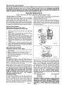
iNTRODUCTION
DOUBLE INSULATION
is a concept in safety, in
electric power tools, which eliminates the need for
the usual three wire grounded power cord and
grounded supply system. Wherever there is electric
current in the tool there are two complete sets of
insulation to protect the user. All exposed metal
parts are isolated from the internal metal motor
components with protecting
insulation.
GENERAL
Your router is a versatile woodworking
tool which
will give you years of trouble-free performance. It is
engineered with the professional in mind, but its
ease of operation allows the amateur to produce
IMPORTANTmServicing
of a tool with double insulation requires extreme care and knowledge of the
system and should be performed only by a qualified
service technician.
For service we suggest
you
return the tool to your nearest Sears Store for repair.
Always use original factory replacement parts when
servicing.
work which is beautiful and precise. All the bearings
in this tool are lubricated with a sufficient amount of
high grade lubricant for the life of the unit under norreal operating
conditions,
therefore,
no further
lubrication
is required.
RULES FOR SAFE OPERATION
WARNING -- DO NOT ATTEMPT TO OPERATE UNTIL YOU HAVE READ THOROUGHLY AND UNDERSTAND
COMPLETELY ALL INSTRUCTIONS, RULES, ETC. CONTAINED IN THIS MANUAL. FAILURE TO COMPLY CAN
RESULT IN ACCIDENTS
INVOLVING FIRE, ELECTRIC SHOCK, OR SERIOUS PERSONAL INJURY. SAVE
OWNERS MANUAL AND REVIEW FREQUENTLY FOR CONTINUING SAFE OPERATION, AND INSTRUCTING
POSSIBLE THIRD-PARTY USER.
READ ALL INSTRUCTIONS
1. KNOW YOUR POWER TOOL -- Read owner's manual carefully. Learn its applications and limitations as well as the specific potential hazards peculiar to
this tool.
2. GUARD AGAINST ELECTRICAL SHOCK BY PREVENTING BODY CONTACT
WITH GROUNDED SURFACES. For example: Pipes, radiators, ranges, refrigerator enclosures.
3. KEEP GUARDS IN PLACE and in working order.
4. KEEP WORK AREA CLEAN. Cluttered areas and benches invite accidents.
5. AVOID DANGEROUS ENVIRONMENT.
Don't use power tool in damp or wet
locations or expose to rain. Keep work area well lit.
6. KEEP CHILDREN AWAY. All visitors should be kept safe distance from work
area. Do not let visitors contact tool or extension cord.
7. STORE IDLE TOOLS. When not in use, tools should be stored in dry, high or
locked-up place = out of reach of children.
8. DON'T FORCE TOOL. It will do the job better and safer at the rate for which it
was designed.
9. USE RIGHT TOOL. Don't force small tool or attachment to do the job of a heavy
duty tool. Don't use tool for purpose not intended - for example - Don't use
a circular saw for cutting tree limbs or logs.
10. WEAR PROPER APPAREL. No loose clothing or jewelry to get caught in moving
parts. Rubber gloves and footwear are recommended
when working outdoors.
Also, wear protective hair covering to contain long hair.
Page 2
RULES FOR SAFE OPERATION (Continued)
11. USE SAFETY GLASSES with all tools. Also face or dust mask if cutting
operation is dusty.
12. DON'T ABUSE CORD= Never carry tool by cord or yank it to disconnect from
receptacle. Keep cord from heat, oil and sharp edges.
13. SECURE WORK. Use clamps or a vise to hold work. It's safer than using your
hand and it frees both hands to operate tool.
14. DON'T OVERREACH. Keep proper footing and balance at all times.
15. MAINTAIN TOOLS WITH CARE= Keep tools sharp at all times, and clean for best
and safest performance. Follow instructions for lubricating and changing accessories.
16. DISCONNECT TOOLS. When not in use, before servicing, or when changing attachments, blades, bits, cutters, etc., all tools should be disconnected.
17. REMOVE ADJUSTING KEYS AND WRENCHES. Form habit of checking to see
that keys and adjusting wrenches are removed from tool before turning it on.
18. AVOID ACCIDENTAL STARTING. Don't carry plugged-in tools with finger on
switch. Be sure switch is off when plugging in.
19. OUTDOOR USE EXTENSION CORDS. When tool is used outdoors, use only
extension cords suitable for use outdoors. Outdoor approved cords are marked
with the suffix W-A, for example -- SJTW-A or SJOW-A.
20. KEEP CUTTERS CLEAN AND SHARP. Sharp cutters minimize stalling and kick=
back.
21. KEEP HANDS AWAY FROM CUTTING AREA. Keep hands away from cutters. Do
not reach underneath work while cutter is rotating. Do not attempt to remove
material while cutter is rotating.
22. NEVER USE IN AN EXPLOSIVE ATMOSPHERE. Normal sparking of the motor
could ignite fumes.
23. INSPECT TOOL CORDS PERIODICALLY and if damaged, have repaired at your
nearest Sears Repair Center.
24. INSPECT EXTENSION CORDS PERIODICALLY and replace if damaged.
25. KEEP HANDLES DRY, CLEAN, AND FREE FROM OIL AND GREASE. Always
use a clean cloth when cleaning. Never use brake fluid, gasoline, or any strong
solvents to clean your tool.
26. STAY ALERT. Watch what you are doing and use common sense. Do not operate tool when you are tired.
27. CHECK DAMAGED PARTS. Before further use of the tool, a guard or
other part that is damaged should be carefully checked to determine that it will
operate properly and perform its intended function. Check for alignment of moving parts, binding of moving parts, breakage of parts, mounting, and any other
conditions that may affect its operation. A guard or other part that is damaged
should be properly repaired or replaced by an authorized service center unless
indicated elsewhere in this instruction manual.
28. DO NOT USE TOOL IF SWITCH DOES NOT TURN IT ON AND OFF. Have defective switches replaced by authorized service center.
29. Inspect for and remove all nails from lumber before routing.
30. DRUGS, ALCOHOL, MEDICATION. Do not operate tool while under the influ.
ence of drugs, alcohol, or any medication.
31. SAVE THESE INSTRUCTIONS.
The operation of any Router can result in foreign objects being thrown
into the eyes, which can result in severe eye damage. Always wear
safety glasses or eye shields before commencing power tool opera.
tion. We recommend Wide Vision Safety mask for use over spectacles
or standard safety glasses, available at Sears Catalog Order or Retail
Stores.
Page 3
OPERATION
WARNING: YOUR ROUTER SHOULD NEVER BE PLUGGED IN WHEN YOU ARE ASSEMBLING
PARTS OR
MAKING ADJUSTMENTS. ALWAYS WEAR SAFETY GLASSES OR EYESHIELDS BEFORE BEGINNING POWER
TOOL OPERATION.
If any parts are missing
do not operate your Router until the missing
parts are replaced.
Before attempting to use your Router, familiarize yourself with all operating features (See Fig. 1) and safety requirements.
WARNING: DO NOT ALLOW FAMILIARITY WITH YOUR ROUTER TO MAKE YOU CARELESS.
REMEMBER THAT A CARELESS FRACTION OF A SECOND IS SUFFICIENT TO INFLICT SEVERE INJURY.
CHIP SHIELD
A clear plastic chip shield is installed on the front of the router for protection against flying dust and chips. The
chip shield is designed to fit the front opening of the router base as shown in figure 1. If necessary to remove,
squeeze the tabs on each end and pull outward. To replace, squeeze the tabs at each end, fit into the opening,
then release. DO NOT USE ROUTER WITHOUT CHIP SHIELD PROPERLY IN PLACE.
SPINDLE
LOCK
DEPTH
RING
iNDICATOR
POINT
DEPTH
INDICATOR
RING
SHIELD
FRONT VIEW
POWER
:ORD
CLAMPING
WiNG NUT
REAR ViEW
Page 4
Fig. 1
OPERATION
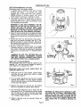
INSTALLING/REMOVING
CUTTERS
Disconnect router from power supply.
1. A spindle lock is located on the side of motor
housing. See figure 1. To activate
lock, push
spindle lock in and slide into lock position.
NEVER attempt to activate spindle lock while
router motor is running or coasting to a stop.
2. Turn collet nut with wrench until lock mechanism
interlocks. See Fig. 2. NOTE: Spindle lock is
spring loaded and will snap into position when
lock mechanism interlocks.
WARNING: IF YOU ARE CHANGING
A BIT IMMEDIATELY AFTER USE, BE CAREFUL NOT TO
TOUCH
THE BIT OR COLLET WITH YOUR
HANDS OR FINGERS. THEY WILL GET BURNED
BECAUSE OF THE HEAT BUILDUP FROM CUTTING. ALWAYS USE THE WRENCH PROVIDED.
3. Place the router upside down on a table and insert
shank of cutter into collet. The shank of your cutter should be close to but not touching bottom of
collet.
Fig. 2
4. Tighten the collet nut securely by turning clockwise with the wrench provided. See fig. 3. Put
spindle lock back in unlock position. Otherwise
the interlocking
mechanism
of the spindle lock
will not let your router turn on.
5. Remove cutters by turning collet nut counter
clockwise
enough to allow cutter to slip easily
from collet. The collet is machined to precision
tolerances to fit cutters with 1/4" diameter shank
size.
WARNING: DO NOT USE CUTTERS WITH UN.
DERSIZED
SHANKS.
UNDERSIZED
SHANKS
WILL NOT TIGHTEN PROPERLY AND COULD
BE THROWN FROM TOOL CAUSING INJURY.
EHCH
TO TIGHTEN
COLLETNUT
TO LOOSEN
COLLET HUT
Fig.3
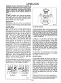
DEPTH OF CUT ADJUSTMENTS
We recommend that cuts be made at a depth not exceeding 1/8" and that several passes be made to
reach depths of cut greater than 1/8".
Disconnect router from
justing for depth of cut.
power
supply before
ad.
DEPTH
1. Place the router on a flat surface, loosen clamping Wing Nut, and adjust until cutter is inside
subbase. See figure 4.
ADJUSTING --_
RING
"
,
.
.
_
/-CLAMMHG
POINT
2. Turn the depth adjusting ring until tip of cutter
touches
flat surface. Turn the depth indicator
ring until the zero lines up with the indicator point
on the base. See figure 4.
3. Position the router so that the bit can extend
below the subbase for desired depth setting.
4. Turn the depth adjusting ring to obtain the desired depth of cut. The distance the cutter moves
can be read on the depth indicator
ring. Each
notch on the depth adjusting ring indicates 1/64
inch change in depth setting.
5. Tighten clamping
eratlng router.
wing
nut securely
before
opo
Page 5
INDICATOR
WING HUT
Fig. 4
WARNING: BE ABSOLUTELY CERTAIN CLAMP.
ING WING NUT IS FIRMLY TIGHTENED.
FAIL.
URE TO DO THIS WILL RESULT IN THE MOTOR
MOVING INSIDE THE BASE, CAUSING AN UNEVEN CUT. THIS COULD CAUSE LOSS OF CONTROL RESULTING IN POSSIBLE SERIOUS IN.
JURY.
OPERATION
WARNING: ALWAYS WEAR SAFETY GLASSES OR
EYESHIELDS WHEN USING YOUR ROUTER. IF THE
CUTTING OPERATION IS DUSTY, ALSO WEAR A
FACE OR DUST MASK. FAILURE TO DO SO COULD
RESULT IN DUST OR CHIPS BEING THROWN IN
YOUR EYES RESULTING IN POSSIBLE SERIOUS INJURY.
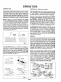
ROUTING
For ease of operation your router has two handles,
one on each side of the router base. When using
your router hold it firmly with both hands as shown
in Fig. 5. Remain alert and watch what you are doing.
Do not operate router when fatigued.
RATE.OF-FEED
IMPORTANT:
The whole "secret"
of professional
routing and edge shaping lies in selecting the proper
rate-of-feed..,
and in making a careful set-up for the
cut to be made.
FORCE FEEDING
Clean, smooth routing and edge shaping can be
done only when the bit is revolving at a relatively
high speed and is taking very small bites to produce
tiny, cleanly severed chips. If the router is forced to
move forward at a fast pace, the rpm of the bit is
slower than normal in relation to its forward movement -- and the bit must necessarily
take bigger
bites as it revolves. "Bigger
bites"
mean bigger
chips, and a rougher finish. Moreover, bigger chips
require more power -- and the router motor can
become sufficiently overloaded to slow down and
further aggravate the condition.
In fact, under extreme force-feeding
conditions the relative rpm of
the bit can become so slow -- and the bites it has to
take so large -- that chips will be partially knocked
off (rather than fully cut off), with resulting splintering and gouging of the workpiece. See Fig. 6.
Your Craftsman
Router is an extremely high-speed
tool (25,000 rpm no-load speed), and will make clean,
smooth cuts if allowed to run freely without the
overload of a forced (too fast) feed. What constitutes
"force feeding" depends upon three things: Bit size,
depth-of-cut,
and workpiece characteristics.
The
larger the bit and/or the deeper the cut, the more
slowly the router can be moved forward. And, if the
wood is very hard, knotty, gummy or damp, the
operation must be slowed still more.
You can always detect "force feeding" by the sound
of the motor. Its high-pitched
whine will sound lower
and stronger as it loses speed. Also, the strain of
holding the tool will be noticeably increased.
TOO FAST
TOO SLOW
Fig. 6
Fig. 5
TOO SLOW FEEDING
It is also possible to spoil a cut by moving the router
forward too slowly. When it is advanced into the
work too slowly a revolving bit doesn't dig into new
wood fast enough to take a bite; instead, it simply
scrapes away sawdust-like
particles. Scraping produces heat, which can glaze or burn and mar the cut
m in extreme cases, can even overheat the bit so as
to destroy its hardness.
In addition, it is more difficult
to control a router
when the bit is scraping instead of cutting. With
practically no load on the motor the bit will be revolving at close to top rpm, and will have a much greater
than normal tendency to bounce off the sides of the
cut (especially, if the wood has a pronounced grain
with hard and soft areas). As a result, the cut produced may have rippled, instead of straight, sides
and, unless very firmly held, the router might even
take off in a wrong direction from the intended cut
line. See Fig. 6.
You can detect "too-slow feeding" by the runaway,
too-highly pitched sound of the motor; or, by feeling
the "wiggle"
of the bit in the cut.
PROPER FEEDING
The right feed is neither too fast nor too slow. It is
the rate at which the bit is being advanced firmly and
surely to produce a continuous spiral of uniform
chips -- without hogging into the wood to make
large individual chips nor, on the other hand, to
create only sawdust. If you .are making a small
diameter, shallow groove in soft, dry wood, the proper feed may be about as fast as you can travel your
router along your guide line. Contrarywise, if the bit
is a large one, the cut is deep, and/or the wood is
hard to cut, the proper feed may be a very slow one.
Then, again, a cross-grain cut may require a slower
pace than an identical with grain cut in the same
workpiece.
There is no fixed rule. You will learn by experience...
by listening to the tool motor and by feeling the progress of each cut. If at all possible, always test a cut
on a scrap of the workpiece wood, beforehand.
Page 6
OPERATIO
DEPTH OF CUT
DIRECTION OF FEED AND THRUST
As previously mentioned, the depth of cut is important because it affects the rate of feed which, in turn,
affects the quality of a cut (and, also, the possibility
of damage to your router motor and bit). A deep cut
requires a slower feed than a shallow one; and a toodeep cut will cause you to slow the feed so much
that the bit is no longer cutting; is scraping, instead.
The router motor and bit revolve in a clockwise direction. This gives to the tool a slight tendency to twist
(in your hands) in a counterclockwise
direction,
especially when the motor revs up (as at starting).
Making a deep cut is never advisable. The smaller
bits -- especially those only 1/16 inch in diameter
are easily broken off when subjected to too much
side thrust. A large enough bit may not be broken off,
but if the cut is too deep a rough cut witl result m
and it may be very difficult
to guide the bit as
desired. For these reasons, we recommend that you
do not exceed 1/8 inch depth of cut in a single pass,
regardless of the bit size or the softness or condition
of the workpiece. See Fig. 7.
DEPTH
OF CUT
OF CUT
_a_-
To make deeper cuts it is therefore necessary to
make as many successive passes as required, lowering the bit 1/8 inch for each new pass. In order to
save time, do all the cutting necessary at one depth
setting, before lowering the bit for the next pass.
This will also assure a uniform depth when the final
pass is completed. See Fig. 8.
2HD.
PASS
+°+It/
tST,
j!,,
To guard against such a kickback, plan your set-up
and direction
of feed so that you will always be
thrusting the tool -- to hold it against whatever you
are using to guide the cut -- in the same direction
that the leading edge of the bit is moving. In short,
the thrust should be in a direction that keeps the
sharp edges of the bit continuously
biting straight
into new (uncut) wood.
ROUTING
WIDTH
Fig. 7
¢-_
Because of the extremely high speed of bit rotation
during a "proper feeding" operation, there is very Iito
tie kickback to contend with under normal condio
tions. However, should the bit strike a knot, hard
grain, etc. that would affect the normal progress of
the cutting action, there will be a slight kickback
sufficient to spoil the trueness of your cut if you are
not prepared. Such a kickback is always in the direction opposite to the direction of bit rotation.
PASS
Whenever you are routing a groove, your tool travel
should be in a direction that places whatever guide
you are using at the right-hand side. In short, when
the guide is positioned as shown in the first part of
Fig. 9, tool travel should be left to right and
counterclockwise around curves. When the guide is
positioned as shown in the second part of Fig. 9,
tool travel should be right to left and clockwise
around curves. If there is a choice, the first set-up is
generally the easiest to use. In either case, the
sideways thrust you use is against the guide.
Whenever you are shaping an edge, the feed should
always be clockwise when working on an outside
(convex) edge; but should
be counterclockwise
when working on an inside (concave) edge. See Fig.
10. The reason for this is that, when traveling the
tool as instructed, the bit will have a "chopping aetion" _ but will have a "gouging
action" if you
reverse the travel direction.
"Chopping"
is much
preferable to "gouging"
as there is less danger of
ripping out chips by tearing the wood grain.
7;Ty/
.OT .
FK --_mO
GUIDE
,E ,NGX,
V
_X
ROTATION
__T::_::_
r
Fig. 8
GUIDE
OUTSIDE
GUIDE
_
IIOIA,ION,
--:'_
++.
ROTA,IO.('_
"
_+
_"
I-H.
U $+_
"
_
L_
EDGE
+
FI[O
GUlOl
-
EDGE
}'
+
"_,-_"
THRUSTIf_
ROTAT|ONd_
FEED
_'(
"
.E,4_
/_
'
GUIO|
"-'_
FlieD
eOTAIION
ROTATION
ROT
AT,ON
BUSY
'
INSIDE"_
_
INSIDE
LEADING
=_
"OUTS;DE
"="T
_
.OTAT,O.
-_..
TH RUST'/l_;"_
i/
_/"1
,_.,://,/
Iu$I
A "CHOPPING"
ACTION
A "GOUGING"
//
Fig. 9
Page 7
ACTION
Fig. 10
STARTING
AND ENDING A CUT
OPE P,ATIO
INTERNAL ROUTING
Tilt Router and place on workpiece, letting edge of
subbase contact workpiece first. Be careful not to let
Router bit contact workpiece. Turn Router on and let
motor build to its full speed. Gradually feed cutter into workpiece until subbase is level with workpiece.
WARNING: KEEP A FIRM GRIP ON ROUTER WITH
BOTH HANDS AT ALL TIMES• FAILURE TO DO SO
COULD RESULT IN LOSS OF CONTROL LEADING
TO POSSIBLE SERIOUS INJURY. Upon completion
of cut, turn motor off and let it come to a complete
stop before removing Router from work surface.
WARNING: NEVER PULL ROUTER OUT OF WORK
AND PLACE UPSIDE DOWN ON WORK SURFACE
BEFORE THE MOTOR STOPS.
EDGING WITH THE PILOT BITS
The arbor-type bits with pilots are excellent for
quick, easy edge shaping of any workpiece edge that
is either straight or curved at a curvature as great or
greater than the radius of the bit to be used. The pilot
prevents the bit from making too deep a cut; and
holding the pilot firmly in contact with the workpiece
edge throughout prevents the cut from becoming
too shallow.
Whenever the workpiece thickness together with the
desired depth of cut (as adjusted by router depth setting) are such that only the top part of the edge is to
be shaped (leaving at least a 1/16 in. thick uncut pottion at bottom), the pilot can ride against the uncut
portion, which will serve to guide it. See Fig. 11.
However, if the workpiece is too thin and/or the bit
set too low so that there will be no uncut edge to ride
the pilot against, any extra board to act as a guide
must be placed under the workpiece. This "guide"
board must have exactly the same contour
straight or curved -- as the workpiece edge. If it is
positioned
so that its edge is flush with the
THE FOLLOWING
PRINTED.
RECOMMENDED
ACCESSORIES
EDGE ROUTING
Place Router on workpiece, making sure the Router
bit does not contact workpiece. Turn Router on and
let motor build to its full speed. Begin your cut,
gradually feeding cutter into workpiece. WARNING:
KEEP A FIRM GRIP ON ROUTER WITH BOTH
HANDS AT ALL TIMES. FAILURE TO DO SO COULD
RESULT IN LOSS OF CONTROL
LEADING TO
POSSIBLE SERIOUS INJURY. Upon completion of
cut, turn motor off and let it come to a complete stop
before removing Router from work surface. WARN.
ING: NEVER PULL ROUTER OUT OF WORK AND
PLACE UPSIDE DOWN
ON WORK
SURFACE
BEFORE THE MOTOR STOPS.
workpiece edge, the bit will make a full cut (in as far
as the bit radius). On the other hand, if the guide is
positioned
as shown in Fig. 11 (out from the
workpiece edge), the bit will make less than a full cut
m which will alter the shape of the finished edge.
TOP EDGE
I VEINING
I
BITS
I
I
SHAPING
WHOLE
EOGE
SHAPINGFig. 11
NOTE: Any of the piloted bits can be used without a
pilot for edge shaping with guides, as preceding. The
size (diameter) of the pilot that is used determines
the maximum cut width that can be made with the
pilot against the workpiece edge (the small pilot exposes all of the bit; the large one reduces this
amount by 1/16 inch).
WERE AVAILABLE
Dovetail Template (9.2579)
Box Joint Template (9.2580)
Butt Hinge Template (9 2575)
Butt Hinge Template (9.2564C)
Router-Crafter
(9 2525C)
Multi-Purpose
Router Guide (_25179)
COMBINATION
PANEL
CUTTER
ROUTER
ROUTER
AT THE TIME THIS MANUAL
WAS
Template Guide Bushings (9 25082)
Rout-A-Form
Pantograph 9(_9_
25183)
Template Set (9 25182)
Sharpening Kit (_966501)
Carrying Case (9 14701)
Full View Router Base (_925086)
HINGE
DOVET._JL
CORE BOX STRAIGHT COMBIFACE
NATION MORTISING CUTTER
BIT
BITS
STRAIGHT,
BIT
BITS
BEVEL
CUTTER
COVE
BIT
BIT
I
25572-3/8"
25571-1/2"
3/18"
25585
BEAD
QUARTER.
ROUND
BITS
ARBOR
2589
°25576-3/8"
"25575°1/2"
I
25596-1/2"
RI
I
M,
•
V=GROOVE
CHAMFER
2552-1/8"
25521-1/4"
25522-3/8"
25523-1/2"
25529-3/4"
25599-1/16"
.......
=_4.1/q"
• 25541-3/8"1
2559-1/8"
25592-3/16"
25593-7/32"
I 25594-1/4"
OOUBLE END
25545 45 °, 60 =
V-GROOVE
2557-1/2"
'25578-t/2"
CAUTION:
"25524-1/4"
"25525-5/16"
"25826-3/8"
"25827-1/2"
FOR FO_
"2541
1/4,5/18,1ROMAN
VENEER
CUTTER
STRAIGHT
"25413
3/5"
1/2"
2555
2553-1/4"
25531-1/2"
25581
O
_o
BIT
25583-1/4"
25562-3/8"
25561-1/2"
25589
"25586-3/8"
*25565-1/2"
CHAMFER
25587-5/32"
25588-1/4"
*25582
BEVEL
"25412
The use of attachments
or accessories
Page 8
not listed above might be hazardous.
WITH 2
BALL
BEARINGS
(1/2 & 5/9"}_i
25895
ROUTING WITH GUIDE BUSHINGS
When using Template Guide Bushings Cat. No. 9-25082 with your Router you must visually center the bit with
the bushing before beginning your cut. The Router subbase may be adjusted by loosening the screws holding
the subbase to the Router. After centering bit with bushing tighten screws firmly. WARNING: FAILURE TO
CENTER BIT WITH BUSHING OR TO FIRMLY TIGHTEN SCREWS AFTER CENTERING COULD CAUSE BIT TO
COME IN CONTACT WITH BUSHING RESULTING IN SERIOUS INJURY.
MAINTENANCE
WHEN
SERVICING
USE ONLY IDENTICAL RF=PLACEMENT PARTS
A cutter sharpening kit (cat. #66501) is available from
PROPER CARE OF CUTTERS
Sears Catalog Order or Retail Store.
Get faster more accurate cutting results by keeping
PROPER
CARE OF COLLET
cutters clean and sharp. Remove all accumulated
From
time
to time, it also becomes necessary to
pitch and gum from cutters after each use.
clean your collet and collet nut. To do so, simply
When sharpening cutter, sharpen only the inside of
remove collet nut from collet and clean the dust and
the cutting edge. Never grind the outside diameter.
chips that have collected. Then return collet nut to
Be sure when sharpening the end of a cutter to grind
its original position.
the clearance angle the same as originally ground.
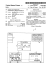
SWITCH REPLACEMENT
Disconnect router from power supply.
SWITCH REPLACEMENT IS AS FOLLOWS:
1.
2.
3.
4.
5.
6.
Remove screws (A) and handle covers (B). See
Figure 12.
Note location of grommet (C) in handle and how
each lead is connected to switch.
Remove leads from switch by inserting a 1/32"
diameter pin or nail into switch lead receptacle
as shown in figure 12 and pulling on the lead.
Make sure grommet (C) is on cord and push each
lead as far as possible into proper receptacle in
switch.
Locate switch in handle and place leads so they
won't be pinched when handle cover is replaced.
Make sure grommet (C) is in place and replace
handle cover and screws,
LIGHT BULB REPLACEMENT
Disconnect router from power supply.
1. Remove cutter from router. Adjust router to maximum height.
2. Remove screws (A) and subbase (B). See Fig. 13.
3. Remove screw (C) and work light lens (D).
4. With bulb pointing toward you, push bulb in and
turn to the left to remove.
5. Reassemble all parts.
GENERAL
Only the parts shown on parts list, page eleven, are
intended to be repaired or replaced by the customer.
All other parts represent an important
part of the
double insulation
system and should be serviced
only by a qualified service technician.
Avoid using solvents when cleaning plastic parts.
Most plastics are susceptible
to various types of
commercial
solvents and may be damaged by their
use. Use _lean cloths to remove dirt, carbon dust,
etc. WARNING: DO NOT AT ANY TIME LET BRAKE
FLUIDS, GASOLINE,
PENETRATING
OILS, ETC.
COME IN CONTACT WITH PLASTIC PARTS. THEY
CONTAIN
CHEMICALS
THAT
CAN
DAMAGE
AND/OR DESTROY PLASTICS.
EXTENSION CORDS
The use of any extension cord will cause some loss
of power. To keep the loss to a minimum and to prevent tool overheating, follow the recommended
cord
sizes on the chart at right. When tool is used outdoors, use only extension cords suitable for outdoor
use and so marked. Extension cords are available at
Sears Catalog Order or Retail Stores.
Page 9
Fig. 12
Fig. 13
When electric tools are used on fiberglass
boats,
sports cars,, etc., it has been found that they are subject to accelerated
wear and possible
premature
failure, as the fiberglass
chips and grindings
are
highly abrasive to bearings, brushes, commutators,
etc. Consequently
it is not recommended
that this
tool be used for extended work on any fiberglass
material. During any use on fiberglass it is extremely
important that the tool is cleaned frequently by blowing with
an air jet. ALWAYS
WEAR SAFETY
GLASSES OR EYESHIELDS BEFORE BEGINNING
THIS OPERATION.
Extension Cord Length
Wire Size A.W.G.
25-50 Feet
18
50-75 Feet
16
75-100 Feet
14
WARNING: CHECK EXTENSION CORDS BEFORE
EACH USE. IF DAMAGED, REPLACE IMMEDIATELY.
NEVER USE TOOL WITH A DAMAGED CORD SINCE
TOUCHING THE DAMAGED AREA COULD CAUSE
ELECTRICAL SHOCK RESULTING IN SERIOUS INJURY.
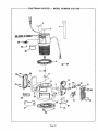
CRAFTSMAN
ROUTER -- MODEL NUMBER 315,17560
_--=--29
2O
Page 10
CRAFTSMAN
ROUTER
w
MODEL
NUMBER
315,17560
The Model Number will be found on a plate attached to the End Cap. Always
mention the Model Number in all correspondence regarding your ROUTER
or when ordering repair parts.
SEE BACK PAGE FOR PARTS ORDERING INSTRUCTIONS
PARTS LiST
1
989935,O03
Wrench ......................................................
2
989610-_)1
Caution
3
200738-001
Data Plate ....................................................
4
989652-001
6
989985-003
Depth Adjust Ring and Indicator Assembly .........................
Collet Nut .................................................
7
623815,002
Clamping Wing Nut ............................................
I
8
612442.435
Base .........................................................
1
9
623166-002
Sq. Hd. Bolt ...................................................
1
11
611457-000
Power Handle Assembly ........................................
1
12
610951-001
Light Bulb (Standard Automotive
1
13
610930001
Light Housing .................................................
14
606066-002
"Screw (#10-32 x 11/16 Pan Hd.) ...................................
4
15
617966-007
17
623814-004
*Screw (#8-10 x 1/2 Pan Hd. T.C.) ..................................
Switch .......................................................
8
1
18
610946-001
Work Light Lens ...............................................
1
19
612191-004
Subbase ......................................................
1
20
998586.001
21
606688-001
Chip Shield ...................................................
1
22
610956-001
Logo Plate ....................................................
1
23
726676,002
Set Screw (#8-32 x 7/16 Hex Socket, Self Locking) ....................
1
24
611456-000
Handle Assembly ..............................................
1
25
990757-001
H. P. Logo ....................................................
1
26
512866-001
27
512639-001
Cap Screw (#5,40 x 1/4 Soc. Hd.) ..................................
Actuator ......................................................
I
1
29
623782-001
Grommet .....................................................
1
33
989684-001
612547.243
Label .................................................
Bulb #1004) .......................
"Screw (#10-32 x 1/4 Pan Hd.) .....................................
"Screw
(#6-32 x 1/4 T.F.) .........................................
1
1
1
1
_. . .
1
3
1
Owner's Manual (Not Illustrated)
NOTE "A" = The assembly shown represents an Important part o! the Double Insulated System. To avoid the poss.
Iblllty of alteration or damage to the System, service should be performed by your nearest Sears Repair Center,
Contact your nearest Catalog Order or Retail Store.
*Standard
**Available
Hardware Item -- May Be Purchss_l
From DIv. _ _ Source 980.00
Locally
Page 11
_ARS
OU T
OWNERS
MANUAL
DOU
SERVICE
Now that
LE iNSULATED
you have purchase(J
your
Router,
should
a
need ever exist for repair parts or service,
simply
contact
any Sears Service Center and most Sears,
Roebuck and Co. stores. Be sure to provide all pertinent facts when you call or visit.
MODEL NO.
315.17560
HOW TO ORDER
REPAIR PARTS
The model number of your Router
the plate attached
to the end cap.
WHEN ORDERING
THE FOLLOWING
will
REPAIR PARTS,
INFORMATION:
be found
ALWAYS
® PART NUMBER
® PART
• MODEL NUMBER
315.17560
o NAME OF ITEM
Router
on
GIVE
DESCRIPTION
All parts listed may be ordered from
vice Center and most Sears stores.
any Sears
Ser-
If the parts you need are not stocked
locally, your
order will be electronically
transmitted
to a Sears
Repair Parts Distribution
Center for handling.
SEARS, ROEBUCK
AND CO., Dept. 698/731A,
Sears Tower,
Chicago,
IL 60684