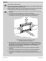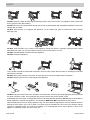
1
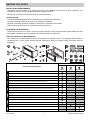
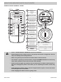
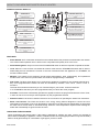
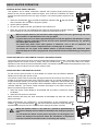
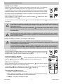
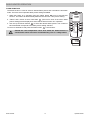
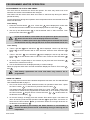
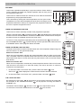
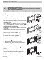
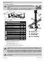
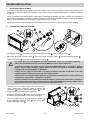
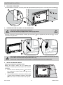
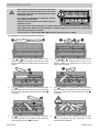
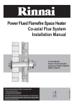
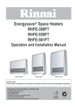
OPERATION & INSTALLATION MANUAL
Power Flued Flamefire
Gas Space Heater RHFE-950ETR
This appliance shall be installed in accordance with:
• Manufacturer’s Installation Instructions
• Current AS/NZS 5601 AS/NZS 3000
• Local Regulations and Municipal Building Codes including local OH&S requirements
This appliance must be installed, maintained and removed by an Authorised Person.
For continued safety of this appliance it must be installed and maintained in
accordance with the manufacturers instructions.
All Rinnai gas products
are A.G.A. certified.
Congratulations on the purchase of your Rinnai RHFE-950ETR Flamefire.
We trust you will have many years of comfort and enjoyment from your appliance.
BEFORE PROCEEDING WITH THE OPERATION OR INSTALLATION OF YOUR NEW HEATER
PLEASE READ THIS MANUAL THOROUGHLY AND GAIN A FULL UNDERSTANDING OF THE
REQUIREMENTS, FEATURES AND OPERATION OF YOUR NEW APPLIANCE.
Rinnai Australia
2
Operation & Installation Manual
OPERATION MANUAL
BEFORE YOU START ................................................................................................................. 4
INSTALLATION REQUIREMENTS .................................................................................................................. 4
CERTIFICATION .............................................................................................................................................. 4
FLUE INSTALLATION MANUAL ...................................................................................................................... 4
CARTON CONTENTS / ITEM CHECKLIST ..................................................................................................... 4
ABOUT YOUR NEW RHFE-950ETR SPACE HEATER.............................................................. 5
GENERAL DESIGN LAYOUT........................................................................................................................... 5
REMOTE CONTROL GENERAL LAYOUT ...................................................................................................... 6
REMOTE CONTROL DISPLAY........................................................................................................................ 7
FEATURES....................................................................................................................................................... 7
UNPACKING THE APPLIANCE: ...................................................................................................................... 7
SAFETY........................................................................................................................................ 8
BASIC HEATER OPERATION .................................................................................................. 10
GENERAL NOTES ABOUT IGNITION ........................................................................................................... 10
OPERATION WITHOUT THE REMOTE CONTROL (AUTOMATIC MODE) ................................................. 10
OPERATION WITH THE REMOTE CONTROL ............................................................................................. 10
TURNING ON THE POWER .......................................................................................................................... 11
USING THE REMOTE CONTROL TO OPERATE THE HEATER ................................................................ 11
FLAME FUNCTION ........................................................................................................................................ 12
PROGRAMMED HEATER OPERATION................................................................................... 13
PROGRAMMING THE CLOCK AND TIMERS ............................................................................................... 13
USING THE TIMERS...................................................................................................................................... 13
PRE-HEAT...................................................................................................................................................... 14
USING THE OVERRIDE FUNCTION ............................................................................................................. 14
USING THE EXTRA LOW FUNCTION........................................................................................................... 14
THE LOCK FUNCTION .................................................................................................................................. 14
CARE AND MAINTENANCE ..................................................................................................... 15
CLEANING...................................................................................................................................................... 15
FILTERS ......................................................................................................................................................... 15
WARM AIR VENT ........................................................................................................................................... 15
GENERAL HEATER CHARACTERISTICS .................................................................................................... 16
SERVICE ........................................................................................................................................................ 16
TROUBLE SHOOTING CHECKLIST.............................................................................................................. 17
ERROR CODES ............................................................................................................................................. 17
INSTALLATION MANUAL......................................................................................................... 18
CONTACT INFORMATION........................................................................................................ 32
Rinnai
3
Operation Manual
BEFORE YOU START
INSTALLATION REQUIREMENTS
This heater must be installed by an authorised person. The installation must conform to local regulations. The
installation must also comply with the instructions supplied by Rinnai.
Service and removal must be carried out by an authorised person.
CERTIFICATION
The Rinnai RHFE-950ETR has been certified by the Australian Gas Association.
The AGA Certification Number is shown on the appliance dataplate.
No parts or functions should be modified or permanently removed from the heater.
Please keep these instructions in a safe place for future reference.
FLUE INSTALLATION MANUAL
These instructions are to be used in conjunction with the Rinnai “Power Flued Flamefire Space Heater Co-axial
Flue System Installation Manual” supplied with flue kits ASPDFK or ASPKIT03.
CARTON CONTENTS / ITEM CHECKLIST
The components for RHFE-950ETR heater are supplied in 3 separate cartons, the following tables list which
components are in each carton. Ensure that the components listed are present before proceeding with the
installation.
A
1
B
2
10
C
15
8
9
16 A
3
or
7
12
4
11
13
14
8
16 B
6
5
Carton Contents
Component Descriptions
1
Rinnai RHFE-950ETR Engine.
2
Remote Control.
3
1.5V AAA Batteries (x2)
4
Remote Control Mounting Bracket.
5
Fixings: Screw 8x1 Truss PH ZP (x2), Screw M4 x 20 Pan Phil Zinc (x1).
6
Flue Exhaust Lock (see Flue Installation Manual for details).
7
Cable Tie 300mm.
8
Fascia Mounting Screws (x2 pre-installed in the engine fascia mounting brackets).
9
This Operation and Installation Manual.
10
Ceramic Granules (x2 Bags for use with Log set installations).
11
1/2” BSP x 5/8” UNF Flare Brass Adaptor (x1).
12
1/2” Flare Brass Nut (x1).
13
5/8” UNF Flare Brass Plug (x1).
14
Semi-rigid Stainless Steel gas pipe with 5/8” connections (x1)).
15
Fascia, complete with dress guard.
16
A. Ceramic Log Set (x8 Logs)
16
B. Ceramic Stone Set (x30 Stones).
Rinnai Australia
4
A
B
C
Engine
Fascia
Burn Media
Operation & Installation Manual
ABOUT YOUR NEW RHFE-950ETR SPACE HEATER
GENERAL DESIGN LAYOUT
5
10
1
10
4
2
3
5
1
6
4
2
3
6
1
7
8
9
CONTROL PANEL DETAIL
1
2
3
ERROR DISPLAY
GLAZED FLAME WINDOW
Displays error codes (located behind
fascia and viewed through grill).
4
BURNER MEDIA
7
Dust filter meshing is fixed to the
inlets of the room air return.
6
5
ROOM AIR RETURN /
INLET FILTERS
WARM AIR DISCHARGE VENT
RECEIVER WINDOW /
BLOCKAGE INDICATOR
Remote control receiver/
Indicator for filter/louvre blockages.
9
8
ON / OFF BUTTON
OPERATION INDICATOR
TIMER INDICATOR
Turns the heater On or Off.
Indicates operation status
Indicates timer program status.
10
CONTROL PANEL
Rinnai Australia
5
Operation Manual
ABOUT YOUR NEW RHFE-950ETR SPACE HEATER
REMOTE CONTROL GENERAL LAYOUT
FRONT
REAR
21
11
Stops and Operates the heater
remotely.
Lock Override Extra Low Flame
AM
PM
Temperature Time
Clock Set
Timer 1 Set ON OFF
Timer 2 Set ON OFF
20
12 CONTROL BUTTONS
Used to select the temperature,
flame picture and adjust timers.
13
11
13
Flame
Timer 1
Timer 2
FLAME BUTTON
Sets the flame picture.
14
STANDBY
ON
STANDBY / ON
BUTTON
14
15
TIMER 1 BUTTON
Sets timer program 1.
15
TIMER 2 BUTTON
BATTERY
COMPARTMENT
COVER
22
Sets timer program 2.
17
Extra
Low
Override
16
19
Lock
Time
Set
18
16
OVERRIDE BUTTON
Manually overrides
current timer operation.
17
EXTRA LOW
Energy saving room temperature
control.
18
TIME SET BUTTON
Sets clock and timers.
12
19
LOCK BUTTON
Locks out control to
prevent tampering.
20
21
NOTE
Rinnai Australia
REMOTE DISPLAY
INFRA RED
EMITTER
22
BATTERIES AND
BATTERY COMPARTMENT
The remote control is powered by a pair of
1.5V AAA batteries.
To replace batteries simply unscrew the battery
compartment cover located on the back of the
remote control anti-clockwise, when installing
new batteries ensure that the correct polarity is
observed.
•
Use 2 x 1.5V AAA batteries. NEVER mix old and new batteries.
•
Remove batteries if the remote control is not going to be used for a long period. This will
help avoid damage from leaking batteries.
•
When using Timers press Override to activate remote control functions.
•
If the heater is operating in Override mode, using the STANDBY/ON button will cancel any
future timer operations, these will have to be reset manually.
•
Some fluorescent lights may interfere with the transmission of remote control signals, in
this case changing the position from which you are operating the remote control may
help.
•
Avoid leaving the remote control in direct sunlight and do not place it close to the warm
air discharge louvres of the heater.
•
Avoid dropping the remote control or getting it wet.
6
Operation Manual
ABOUT YOUR NEW RHFE-950ETR SPACE HEATER
REMOTE CONTROL DISPLAY
23
29
MAIN DISPLAY
28
Displays current Clock, Timer or
Temperature status.
24
MAIN DISPLAY MODE
Indicates that controller is in Time
or Temperature display modes.
25
OVERRIDE INDICATOR
Displays when Override has been
selected.
30
23
EXTRA LOW INDICATOR
Displays when Extra Low function
has been selected.
24
31
26
27
FLAME INDICATOR
Displays current flame picture setting
when Flame mode is activated.
32
TIMER 1 INDICATOR
Displays to indicate current status
of Timer 1.
27
29
30
25
CLOCK SET INDICATOR
Displays when the Clock Set mode
is selected.
26
31
32
TRANSMISSION SIGNAL
Displays when data is transmitted.
TIMER 2 INDICATOR
Displays to indicate current status
of Timer 2.
28
LOCK INDICATOR
Displays when the Lock mode is
activated.
FEATURES
•
Room Sealed: Air for combustion is taken from the outside and the flue products are exhausted to the outside.
This means heater operation has no effect on the composition and quality of air in the room.
•
Push Button Ignition: Only one touch of the STANDBY/ON switch is all that is required to operate the heater.
•
Lock: When the Lock function is activated all controls other than the STANDBY/ON switch will be locked.
Deactivating the lock releases the controls. If the lock is activated when the appliance is in STANDBY, all
functions will be locked.
•
Memory: The heaters micro-computer records preset temperatures, timer programming, and operational
modes. Even in the event of a power failure, the need for reprogramming is minimised.
•
Dual Timer: The Dual Timer allows you to program the appliance to operate for two separate periods each
day. Once programmed the heater can then be controlled by selection of the Timer 1 and or Timer 2
functions.
The Dual Timer feature means that you can "Set and Forget" your heater. It will turn itself ON
or to STANDBY at the times you have programmed until you cancel the Timer program.
•
Pre-Heat: This function automatically operates the appliance before the programmed ON time of the Timer,
in order to heat a room to the pre-set temperature by the programmed ON time.
•
Remote Control: Full function cordless remote for the convenience of operating the heater from a distance.
•
Extra Low Function: The Extra low function is an energy saving feature designed to control the room
temperature economically. If the room temperature continues to rise above the set temperature on thermostat
the main burner will turn down to its lowest setting. When the room temperature requires further heating the
heater will automatically re-ignite to warm the room.
UNPACKING THE APPLIANCE:
Check for damage and missing parts. If the heater is damaged or missing any parts, contact your supplier for
advice. Before installing the appliance, check it is labelled for the correct gas type (see label on top rear of heater).
Refer to local gas authority for confirmation of gas type if you are in doubt.
Rinnai Australia
7
Operation Manual
SAFETY
DO NOT MODIFY THIS APPLIANCE.
WARNING
Failure to comply with these instructions could result in a fire or explosion, which could
cause serious injury, death or property damage.
Improper installation, adjustments, service or maintenance can cause serious injury, death
or property damage. Such work must be performed by an authorised person.
a. The appliance must be installed in accordance with the local gas and electrical authority
regulations.
IMPORTANT
b. For information on gas consumption, see data plate on the appliance.
c. This appliance must not be installed where curtains or other combustible materials
could come into contact with it. In some cases curtains may need restraining.
250mm
100mm
100mm
1000mm
The above diagram shows the clearances required
around this heater whilst in operation .
d. Heat emanating from the front of this appliance may over time affect the appearance of
some materials used for flooring such as carpet, vinyl, cork or timber. This effect may be
amplified if the air in the room contains cooking vapours or cigarette smoke. To avoid
this possibility, it is recommended that a mat be placed in front of the appliance,
extending at least 750 mm in front of it.
e. The appliance is not intended for use by young children or infirm persons without
supervision.
f.
Young children should be supervised to ensure they do not play with the appliance.
g. If the supply cord is damaged or requires replacing, it must be replaced by the
manufacturer or the manufacturer's agent or similarly qualified person in order to avoid
a hazard.
Rinnai Australia
8
Operation Manual
SAFETY
DO NOT restrict the warm air discharge by placing articles in front of the heater. This appliance must not be used
for any purpose other than heating.
DO NOT allow anyone to post articles through the louvres or let flammable and combustible materials to come into
contact with the heater.
DO NOT place articles on or against this appliance, on the heaters top panel or obstruct the auto overheat
discharge vent.
DO NOT spray aerosols in the vicinity of this appliance whilst the heater is operating. Most aerosols contain
flammable gas, which can be a fire hazard if used near the heater when it is in use.
DO NOT store flammable materials near this appliance.
DO NOT modify this appliance.
Young children should be supervised at all times. Hand or body contact with the warm air discharge louvres and
glass must be avoided.
DO NOT allow young children or the infirm to sleep directly in front of the heater while in operation.
DO NOT allow anyone to sit on or lean against the appliance.
DO NOT unplug the heater while it is in operation or while the fans are still cycling. Unplugging the heater will cause
any timer operation to stop. Timer programs are stored in the memory of the remote control.
A dedicated 230~240V 50Hz 10 Amp power point must be used with this appliance. DO NOT use power boards or
double adaptors to operate this appliance. The appliance MUST NOT BE located below a power Point.
Heat emanating from the front of this appliance may over time affect the appearance of some materials used for
flooring such as carpet, vinyl, cork or timber. This effect may be amplified if the air in the room contains cooking
vapours or cigarette smoke. To avoid this possibility, it is recommended that a mat be placed in front of the
appliance, extending at least 750 mm in front of it.
Rinnai Australia
9
Operation Manual
BASIC HEATER OPERATION
GENERAL NOTES ABOUT IGNITION
This appliance has a sealed combustion chamber that requires purging before gas is
allowed to flow and the ignition sequence begins. As a result the combustion fan starts
several seconds before there are any signs of ignition. The normal ignition sequence is as
follows:
1. When the On/Off button 7 is pressed the Operation Indicator LED
and Combustion fan will rotate to purge the system.
8
7 8 9
will glow ‘BLUE’
6
1
2. Ignition sparker operates.
7
3. As soon as a spark is sensed, gas will flow to the main burner.
8
4. When the main burner has established the heater will automatically modulate between
burner settings to achieve and maintain the default set temperature of 22°C.
1
9
When using the heater for the first time or after long periods of non use, ignition may not occur
the first time it is operated due to air in the gas pipes.
NOTE
If ignition does not occur within approximately 60 seconds the appliance will attempt to re-light,
however if ignition continues to fail the unit will cease operation automatically. Try operating
the heater again if this occurs.
The heater may make noises after ignition or extinction. This is due to expansion and
contraction of the internal components and is normal page 16 for details.
The heater will not ignite if the ON/OFF button is pressed straight after extinction. After
approximately 20 seconds “purge period” has passed the unit will automatically go into ignition
mode.
OPERATION WITHOUT THE REMOTE CONTROL (AUTOMATIC MODE)
The remote control stores the clock, timer and temperature settings for the heater. The heater can be operated and
stopped without the remote control by simply using the On/Off button 7 on the left hand side of the heater.
Operation in this manner is known as automatic mode. In automatic mode the default set temperature is 22°C. For
operation in other modes the remote control must be used.
OPERATION WITH THE REMOTE CONTROL
For the remote control functions to be available, the heater must be switched between
standby and off using the remote control.
The remote control emits an Infra Red (IR) signal and must be aimed at the receiver unit
located on the bottom right hand corner of the front panel 6 . The normal operating range
is approximately 5 metres, up to an angle of approximately 40 degrees to the horizontal. This
range may vary depending on the position of the installation and the strength of the remote
controller batteries. The remote control transmits information to the heater whenever a
button is pressed except as follows:
1. When the remote control display is de-activated and any button is pressed to restore
the display
21
20
32
11
STANDBY
ON
Timer 1
14
13
Flame
Timer 2
15
17
Extra
Low
Override
16
Lock
Time
Set
18
19
2. When the lock function is activated
Lock OverrideAuto Off Flame
AM
PM
Temperature Time
Clock Set
Timer 1 Set ON OFF
Timer 2 Set ON OFF
When the timers are being set, timer information is transmitted only when the ‘Time Set’
button is pressed.
Signal transmissions are confirmed by a brief illumination of the Transmission Signal
Indicator 32 on the Remote Display 20 and at the heater the Remote Control Indicator 6
will flash and a beep will sound to confirm that the settings have been received.
NOTE
7 8 9
When the remote control is not used for a period of approximately 5
seconds the display will then default to stand-by mode, displaying only the
time.
To re-activate the remote control press any button on the keypad. This
returns the display to the previous mode. No information is transmitted
from the controller to the heater when re-activating the display.
Rinnai Australia
12
10
6
1
Operation Manual
BASIC HEATER OPERATION
TURNING ON THE POWER
Press the On/Off button 7 located on the heater control panel once. The Operation
Indicator 8 will illuminate and glow ‘BLUE’ and the ignition process will commence.
7
8
The heater will continue to operate in the automatic mode to achieve and maintain a default
temperature setting of 22°C until an alternate command is received from the remote control.
If the main power is disrupted whilst the heater is operating, once the power is restored the
heater will go into power failure mode.
This is indicated by a pair of flashing zeros in the Error Display
flashing Operation Indicator 8 .
To reset the heater, press the On/Off button
the heater on.
NOTE
7
1
7
8
window and a ‘RED’
once. Press the STANDBY/ON button
11
1
9
1
9
a second time to switch
To operate the heater in automatic mode without using the remote control, press the main
power switch on the heater off and then on again. The heater will operate with a default set
temperature of 22°C.
If the heater is turned off using the On/Off button
on the heater control panel when it is turned
back on it will loose all timer and clock settings until the remote control is used to re-transmit
this information.
CAUTION
DO NOT unplug the main power supply, to extinguish the flames as this may cause damage.
The convection fan is required to continue operation for several minutes after extinction of the
flames to assist cooling.
USING THE REMOTE CONTROL TO OPERATE THE HEATER
The remote control uses 2 x 1.5V AAA batteries (NEVER mix old and new batteries).
NOTE
Remove batteries if the remote control is not going to be used for a long period. This will help
avoid damage from leaking batteries.
To replace batteries simply unscrew the battery compartment cover located on the back of the
remote control anti-clockwise. When installing new batteries ensure that the correct polarity is
observed, the polarity is engraved into the battery compartment (see the illustration on page 6).
Turning The Heater On
7
When the heater is in standby mode (Operation Indicator 8 illuminated ‘RED’) pressing the
STANDBY/ON button 11 will start the ignition sequence and the Operation Indicator 8
will glow ‘BLUE’ to indicate that the heater is now in operation.
8
1
9
21
Turning The Heater To Stand-By
Press the STANDBY/ON button 11 . This will extinguish all flames and the Operation
Indicator 8 will glow ‘RED’ to indicate the appliance is now in stand-by mode.
23
24
Lock Override Auto Off
AM
PM
Temperature
Timer 1 Set
Timer 2 Set
Adjusting The Temperature
When in automatic mode, pressing the Up and Down buttons
temperature by increments of 1°C with each press.
12
will change the pre-set
"Temperature" 24 will be displayed to confirm that the function has been initiated. The
Remote Display will show the selected temperature 23 in degrees °C.
20
ON OFF
ON OFF
11
STANDBY
ON
Timer 1
14
13
Flame
Timer 2
15
17
Extra
Low
Overide
16
Lock
Time
Set
18
19
The Temperature Can Be Pre-set To:
A.L (Low) – Continuous combustion on low.
B.16°C ~ 26°C (in 1°C steps) – Thermostatic control to pre-set temperature selected.
Combustion rate varies to maintain the selected temperature.
12
C.H (High) – Continuous combustion on high.
Rinnai Australia
11
Operation Manual
BASIC HEATER OPERATION
FLAME FUNCTION
The flame function is used to select a desired flame picture and overrides the automatic
mode. There are seven separate flame picture settings available.
1. While the heater is in operation press the Flame button 13 once to activate this
function. The heater will automatically default to the last used flame picture setting.
21
20
Lock OverrideAuto Off Flame
AM
PM
Temperature Time
Clock Set
Timer 1 Set ON OFF
Timer 2 Set ON OFF
11
STANDBY
ON
Timer 1
14
13
Flame
Timer 2
15
17
Extra
Low
Overide
16
Lock
Time
Set
18
2. "Flame" and a series of seven short bars 31 (one bar for each of the seven flame
picture settings) will be displayed to show that the flame function is in operation.
3. Use the Up and Down buttons 12 to select the desired flame picture. The number of
bars illuminated correspond to the flame picture setting selected.
To return to automatic mode press the Flame button
13
a second time.
Should the room temperature reach 40°C whilst the flame function is
activated the heater will switch off automatically. This is a safety feature.
19
NOTE
12
31
Lock OverrideAuto Off Flame
AM
PM
Temperature Time
Timer 1 Set ON OFF
Timer 2 Set ON OFF
Rinnai Australia
12
Operation Manual
PROGRAMMED HEATER OPERATION
PROGRAMMING THE CLOCK AND TIMERS
The clock must be set before the timers will operate. The clock may need to be re-set
whenever the remote control batteries are changed.
21
This heater has two timers which allow the heater to start and stop during two distinct
periods each day.
20
Lock OverrideAuto Off Flame
AM
PM
Temperature Time
Clock Set
Timer 1 Set ON OFF
Timer 2 Set ON OFF
11
STANDBY
ON
Timer 1
14
13
Flame
Timer 2
15
17
Extra
Low
Overide
16
19
Lock
Time
Set
18
The set temperature during timer operation is the temperature which was selected when the
heater was last used.
Clock Setting
1. Press the Time Set button 18 once. "Clock Set" 25 will be displayed to confirm that
the function has been initiated. The Remote Display will show "AM 12:00" 23 .
2. Use the Up and Down buttons 12 to set the desired "AM" or "PM" clock time. Then
press the Time Set button 18 once.
If you do not want to set the timers at this point then press the Time Set
18 button 4 more times until the display returns to the time.
NOTE
12
If there is no button pressed for approximately 90 seconds then the screen
will deactivate and any settings that have not been transmitted will be lost.
23
25
Timer Setting
3. "Timer 1 Set ON" 26 and "AM 06:00" 23 will be displayed. Use the Up and Down
buttons 12 to set the desired "AM" or "PM" "ON" time. Press the Time Set button 18
once.
23
4. "Timer 1 Set OFF" 26 and "AM 09:00" 23 will be displayed. Use the Up and Down
buttons 12 to set the desired "AM" or "PM" "OFF" time. Press the Time Set button 18
once.
26
5. To set-up Timer 2 repeat steps 3. and 4 above or just press the Time Set button
three times to exit the timer set-up.
23
18
NOTE
Lock OverrideAuto Off Flame
AM
PM
Temperature Time
Timer 1 Set ON OFF
Timer 2 Set ON OFF
Lock OverrideAuto Off Flame
AM
PM
Temperature Time
26
6. The set On/Off timers will be displayed briefly to confirm settings.
When the programs have been received the Remote Display will revert to Time mode
and 24 .
Lock OverrideAuto Off Flame
AM
PM
Temperature Time
Clock Set
Timer 1 Set ON OFF
Timer 2 Set ON OFF
Timer 1 Set
OFF
Timer 2 Set ON OFF
23
After battery replacement the clock and timers may need to be reprogrammed.
23
24
Lock OverrideAuto Off Flame
AM
PM
Temperature Time
Timer 2 Set ON OFF
USING THE TIMERS
Prior to using timers ensure that the desired temperature has been set. See ADJUSTING
THE TEMPERATURE on page 11.
Timer 2 Set ON OFF
1. One or both Timers can be used. While the heater is in operation to start Timer 1 press
the Timer 1 button 14 . To start Timer 2 press the Timer 2 button 15 .
The display briefly shows the status of each Timer (e.g. Timer 1 ON Timer 1 OFF). If the
current time is outside those programmed the heater will go in to stand-by mode and
the Timer Indicator 9 will glow ‘Green’. Each active timer 26 / 27 are also shown on
the Remote Control Display 20 .
2. To turn the Timer(s) off simply press the relevant Timer button again. The heater will
return to stand-by mode and the Operation Indicator 8 will glow ‘RED’, if there are no
timers set the Timer Indicator 9 will go out and the timers are no longer be shown on
the Remote Control Display 20 .
STANDBY
ON
Timer 1
14
Flame
Timer 2
15
Extra
Low
Overide
Lock
Time
Set
Lock
AM
PM
Temperature Time
26
27
Timer 1
Timer 2 Set
NOTE
Rinnai Australia
13
OFF
ON OFF
7
8
When operated by the Timer(s) the Flame Function is not available. If
desired the flame picture can be controlled by raising or lowering the set
temperature.
Auto Off Flame
1
9
Operation Manual
PROGRAMMED HEATER OPERATION
PRE-HEAT
Time elapsed from ignition to pre-set temperature
Average starting time
This function is called Pre-heat as it ensures the room reaches the desired
temperature by the programmed ON time.
Cooler than usual
Warmer than usual
This is achieved by sensing the rooms temperature one hour prior to start.
6:00
The difference in room and set temperatures at the time of sensing the room
temperature determines exactly how long before the programmed ON time
the micro-computer will ignite the burner.
Recorded by Micro-computer
This function operates automatically in conjunction with the Timers. When a
Timer is selected, the heater may operate anywhere within an hour prior to
the programmed ON Time.
6:30
Room
temperature
sensed
7:00
Average
ignition
Earlier than
usual ignition
Timer
programmed
ON time
Later than
usual ignition
USING THE OVERRIDE FUNCTION
This function is used to manually override Timer programmed operation.
29
When the Override button 16 is pressed Override” 29 will be displayed to confirm that the
function has been selected. Whilst in Override mode all remote control functions except for
the flame function are available until the next Timer event.
To return to Timer programmed operation press the Override button
Lock Override Auto Off Flame
AM
PM
Temperature Time
Timer 1
OFF
Timer 2 Set ON OFF
a second time.
16
21
If the STANDBY/ON button 11 is pressed during Override operations the heater will revert
to STANDBY and the Timer programs will be cancelled.
USING THE EXTRA LOW FUNCTION
The Extra Low function is useful in situations when the room temperature keeps rising even
when the heater is on the lowest heat setting.
Extra Low Function ‘OFF’
When the room temperature reaches the preset temperature with the Extra Low function
‘OFF’, the heater continues to operate with the main burner on low to provide a flame picture
with minimal heat output. In some cases this may still cause the room to become warmer
than desired.
20
Lock OverrideAuto Off Flame
AM
PM
Temperature Time
Clock Set
Timer 1 Set ON OFF
Timer 2 Set ON OFF
11
STANDBY
ON
Timer 1
14
13
Flame
Timer 2
15
17
Extra
Low
Overide
16
19
Lock
Time
Set
18
Extra Low Function ‘ON’
When the room temperature exceeds the preset temperature with the Extra Low function
‘ON’ the burner will reduce to an extra low setting. The burner will return to normal to
maintain the set temperature.
1. To switch the Extra Low function ‘ON’, press the Extra Low button
"Extra Low"
30
17
12
30
once.
17
Extra Low Flame
Temperature Time
will be displayed to confirm that the function has been selected.
2. To switch the Extra Low function ‘OFF’, press the Extra Low button
Lock
AM
PM
OFF
Timer 2 Set ON OFF
again.
THE LOCK FUNCTION
By pressing the Lock button 19 all the functions of the remote control will be locked with
the exception of the STANDBY/ON button 11 for the purpose of turning the heater to
STANDBY only.
The Remote Control Display
20
will show "Lock"
28
To cancel the Lock function hold down the Lock button
Rinnai Australia
in the top left hand corner.
19
14
for 3 seconds.
28
Lock Override Auto Off
AM
PM
Temperature Time
Timer 1 Set ON OFF
Timer 2 Set ON OFF
Operation Manual
CARE AND MAINTENANCE
CLEANING
Your heater needs very little maintenance, however the following information will help you keep it looking good and
working efficiently.
NOTE
•
Unplug electrical cord before cleaning.
•
DO NOT USE SOLVENTS. All parts of the heater and remote control can be cleaned using
a soft, damp cloth and a mild detergent.
•
DO NOT attempt to clean the heater while the appliance is hot or operating.
FILTERS
The filter meshing for this appliance is fixed to the inlets of the room
air return
.
Filter Mesh
The build up of dust or other particles on these filter strips reduces the
air flow through to the heater which in turn reduces heater's efficiency
and can lead to the appliance shutting down.
Filter Care
7
Filters require cleaning regularly during the heating season to prevent
these unnecessary cut-outs.
6
1
8
3
Cleaning filter strips:
1
Clean any dust and other debris from both faces of the filters with
either a vacuum cleaner, a soft dry cloth or a soft brush. NEVER
attempt to clean filters with water.
Heater shut down due to filter blockages
DO NOT wait for the Filter Blockage Indicator to come on before
cleaning filters.
DO NOT continue to use the heater once this Indicator is flashing.
When an obstructive build up is detected the Blockage Indicator LED
which is located above the Receiver Window 6 will begin to flash
RED to let you know that there is a problem.
Once the Indicator is flashing if no action is taken the heater will
eventually shut down to avoid overheating and a fault code of 14 will
be displayed in the Error Display 10 window.
Returning the appliance to normal operation after a shut down
To restore to normal operation after a filter blockage shut down do the
following:
1.
Press the On/Off
2.
Remove obstruction (see “Filter Care” on page 15).
3.
Press the On/Off
4.
Use the remote control to resume normal heater operation.
7
7
button once to turn off the heater.
button once to turn the heater back on.
WARM AIR VENT
It is important that the Warm Air Discharge Vent 5 be kept clear of
any obstructions as this will cause your heater to operate less
efficiently.
When an obstruction is detected the Blockage Indicator LED which is
located next to the Receiver Window 6 will illuminate RED and the
combustion state reduces to front burner, low operation only.
To restore normal operation remove the obstruction and use the
remote control to resume normal heater operation.
Rinnai Australia
15
7
6
3
1
8
1
Operation Manual
CARE AND MAINTENANCE
GENERAL HEATER CHARACTERISTICS
Before asking for a service call please check the following table as these characteristics are part of the normal
operation of the appliance and do not indicate a fault.
CHARACTERISTIC
EXPLANATION
At ignition:
Warm air does not start when the burner lights.
The room air fan is started automatically after a short
delay. This is to allow the heat exchanger to warm up,
helping to avoid cold draughts.
Smoke or strange smells are produced on the first
up operation after installation.
This is caused by grease, oil or dust on the heat exchanger
when new. This will stop after a short time.
Sharp clicking noises at ignition, or when the unit
thermostat modulates to a lower or higher setting,
or shuts down.
This is simply expansion and contraction noise from the
heat exchanger and is normal.
During combustion:
Clunking noise when the thermostat operates
This is the sound of the solenoid gas valves opening and
closing to regulate the gas flow and is normal.
When the appliance is turned off:
Convection fan continues to run after turning off.
This is to remove residual heat from the heat exchanger
and stops once the appliance cools.
Other points:
Steam is discharged from the flue terminal.
High efficiency appliances tend to discharge water vapour
on cold days. This is normal.
Heater does not start when the STANDBY / ON
button is pushed, thermostat is on High (H).
Check that the appliance On / Off button is ON. Check
Timer(s). Timer(s) programmes must be turned off or
overridden for manual operation.
Timer(s):
Timer(s) do not operate at set time.
Timer(s) may either be inactivated or incorrectly
programmed. Please confirm Timer(s) are set correctly.
See page 13 for correct Timer(s) operation.
Timer operates for a short period and then cuts
out.
Room temperature may be higher than the set
temperature. Increase set temperature if desired. Cancel
the Auto Off function.
SERVICE
Rinnai recommend that this appliance and installation be inspected and serviced every 2 years.
If the power supply cord or any other component of the heater are damaged, they must be replaced by Rinnai or
a suitably qualified person.
Any service or repair work should only be carried out by an authorised person. Rinnai has service and spare parts
departments nationally, see back cover for contact details.
Service calls for general cleaning, maintenance and wear and tear are not necessarily covered
under the warranty. Service calls of this nature may be chargeable.
NOTE
Faults caused by insufficient gas supply, gas quality, installation errors or operation errors are
not covered by the Rinnai warranty. Refer to separate warranty booklet.
Appliances incorporating a live fuel effect and designed to operate with luminous flames may
exhibit slight carbon deposition on burner media. Slight deposition is acceptable.
Rinnai Australia
16
Operation Manual
CARE AND MAINTENANCE
TROUBLE SHOOTING CHECKLIST
Remote control
doesn’t work
Smell of gas
Combustion stops
during operation
Probable Cause
Burners fail to ignite
Fault Condition
No ignition or control
panel indicators
No Display on remote
Use the following chart to help determine whether a service call is required, however if you are unsure about the
way your heater is operating, contact Rinnai or your local agent.
Possible Remedy
Not plugged in or turned off.
Plug in power cord or press On/Off
button.
Mains power failure.
Use power failure reset procedure on page 11.
(Initial Install) Air in gas pipe.
Installer to purge air from gas supply.
Filter obstructed.
Remove and clean filters.
Gas escape.
Isolate gas supply, call Rinnai service, page 32.
On Timer set.
Use the Override as described on page 14.
Lock set.
Cancel Lock as described on page 14.
Gas supply turned off.
Turn gas supply on at the meter or cylinder.
Flat batteries.
Replace remote control batteries 2 x 1.5v (AAA).
Remote Control lock-up due to mis
operations such as the remote signal
being out of range, incorrectly aimed
or obstructed.
Press the STANDBY/ON 11 button.
ERROR CODES
Your Rinnai space heater is also fitted with self diagnostic electronics that monitor the
appliance during start-up and operation.
7
Should a fault occur the heater will shut down, the fault that has caused the shut down will
be indicated by a pair of flashing digits in the Error Display 10 window and a ‘RED’ flashing
Operation Indicator 8 .
11
Refer to the table below for probable cause and the suggested remedy.
Code
Probable Cause
Mains power failure
STANDBY
ON
Suggested Remedy
To reset the heater, press the On/Off
00
8
1
button twice or use the
remote control and press the STANDBY/ON 11 button once for
stand-by mode, press the STANDBY/ON 11 button a second time
to set the heater to On.
11
Ignition failure
Check gas supply is turned on, switch the heater to Standby and
then On again. If ignition failure continues to occur a Service call will
be required.
12
Incomplete combustion
As above
14
Filter Blockage / Overheat
Clean filters, if error continues service call.
16
Room overheat
Lower room temp to below 40°C.
31
Room temperature sensor faulty
Requires a service call.
32
Overheat temperature sensor faulty
Requires a service call.
33
Overheat temperature sensor faulty
Requires a service call.
53
Spark sensor faulty
Requires a service call.
61
Combustion fan motor faulty
Requires a service call.
71
Solenoids faulty
Requires a service call.
72
Flame detection circuit fault
Requires a service call.
73
Communication error
Requires a service call.
Rinnai Australia
17
Operation Manual
INSTALLATION MANUAL
OPERATION MANUAL................................................................................................................ 3
INSTALLATION GENERAL....................................................................................................... 19
PRODUCT SPECIFICATIONS ...................................................................................................................... 19
APPLIANCE DIMENSIONS ........................................................................................................................... 19
HEATER LOCATION ................................................................................................................. 20
ENCLOSURE REQUIREMENTS ................................................................................................................... 20
WALL PENETRATION REQUIREMENTS ..................................................................................................... 20
GAS SUPPLY ................................................................................................................................................ 21
ELECTRICAL SUPPLY .................................................................................................................................. 21
MANTLE INSTALLATIONS ........................................................................................................................... 21
FLUE INSTALLATION ............................................................................................................... 22
TYPES OF FLUE INSTALLATIONS .............................................................................................................. 22
FLUE SYSTEM TRANSITION CASTING ...................................................................................................... 22
FLUE TERMINAL LOCATION ....................................................................................................................... 23
HEATER INSTALLATION.......................................................................................................... 24
1.
UNPACKING THE APPLIANCE ............................................................................................................. 24
2.
CONNECTING THE FLUE SYSTEM ..................................................................................................... 24
3.
SECURING THE ENGINE ..................................................................................................................... 25
4.
CONNECTING THE APPLIANCE TO THE GAS SUPPLY .................................................................... 25
5.
INSTALLING BURNER MEDIA .............................................................................................................. 25
6.
COMMISSIONING ................................................................................................................................. 28
7.
INSTALLING THE OUTER FASCIA PANEL .......................................................................................... 28
8.
INSTALLING THE DRESS GUARD & INNER FASCIA PANEL ............................................................ 28
9.
INSTALLATION AND COMMISSIONING CHECKLIST ......................................................................... 29
10. INSTALLATION RECORD ..................................................................................................................... 29
11. FINAL CHECKLIST ................................................................................................................................ 29
WIRING DIAGRAM .................................................................................................................... 30
INSTALLATION NOTES ............................................................................................................ 31
CONTACT INFORMATION........................................................................................................ 32
Rinnai
18
Installation Manual
INSTALLATION GENERAL
PRODUCT SPECIFICATIONS
Model: RHFE-950ETR
General description:
Inbuilt Fan Exhaust Balanced Flued Convection Flame Fire with Electronic
Temperature Control, Timer and Remote.
Natural Gas
Propane
Low (MJ/hr):
10
10
High, Extended flue / Direct flue (MJ/hr):
31/34
32/34
Manual On/Off, 3 Heat Settings (electrical touch control). Remote (RF)
8.13
125m2 (cool areas)
Flame burner
(kPa)
1.13 - 3.5
2.5 - 3.5
1/2” BSP flare
Mesh Guard
Fan assisted, twin chamber coaxial flue system, provides air for combustion to the
appliance and allows expulsion of combustion products to atmosphere. Results in
‘room sealed’ appliance.
Double diameter 160mm x 180mm - 3 speed - Centrifugal
Multi port burners
Ceramic Logs or Ceramic Stones
Continuous spark electronic ignition
Push button electronic / Remote control
Overcurrent fuse
Overheat thermistor
Spark detector
Flame failure sensing system
Thermal fuse
Air temperature thermistor
Naturally aspirated burner
Inbuilt Only
Thermostat in remote, wireless remote
Black engine, Black and silver fascia options
70 kg
Gas input rate:
Gas control:
kW Output
Heat-up area (m2)
Burners
Gas Supply Pressure:
Gas Connection:
Guard
Flue System:
Convection Fan:
Combustion system
Burner Media:
Ignition system:
Operation:
Safety devices:
Combustion method:
Installation type:
Thermostat
Colour:
Weight:
The manufacturer reserves the right to change or modify specifications without notice.
APPLIANCE DIMENSIONS
430
65
660
560
420
500 ±25
1070
960
25
568
25
Rinnai Australia
19
Installation Manual
HEATER LOCATION
When positioning the heater the main variables governing the location are Flueing and Warm Air Distribution.
This heater must not be installed where curtains or other combustible materials could come into contact with it. In
some cases curtains may need restraining.
ENCLOSURE REQUIREMENTS
The Rinnai RHFE-950ETR has a cool outer casing allowing it to be installed into existing Masonry fireplace or into
a decorative fireplace constructed from combustible materials such as wood or plaster.
WARNING
For all installations, ONLY Rinnai ASP & ES Flue components MUST BE used. The Rinnai RHFE950ETR MUST NOT be flued into ‘natural draft’ flue system or via a chimney.
Consult the Rinnai “Power Flued Flamefire Space Heater Co-axial Flue System Installation
Manual” supplied with flue kits ASPDFK or ASPKIT03 for detailed flue installation instructions.
A pair of wheels located at the rear the heater allows
it to slide in and out of the enclosure for ease of
commissioning and maintenance. As such the
heater must be positioned on a flat and level surface
that allows free movement.
In a masonry fireplace, use a slurry of sand and
cement to level the base as required.
In a decorative fireplace, if the appliance is elevated
from the ground, a base must be constructed using
a board with supporting joists as shown.
JOIST
RIGHT
WHEEL
h
d
850
The enclosure dimensions specified are critical to the
successful installation of this appliance and must be
strictly adhered to.
w
h
d
WALL PENETRATION REQUIREMENTS
Flue pipe penetration
Mark the location of the gas supply (consumer piping) and flue pipe
penetrations from the centreline 1 of the heater enclosure using the
following dimensions:
1 Centreline of enclosure
65 mm from base of enclosure
JOIST
MDF (Customwood) BOARD, Minimum 20mm
Enclosure Dimensions
Width
980 mm
Height
580 mm
Depth
570 mm (minimum)
w
NOTE
LEFT
WHEEL
1
Gas supply penetration
2 420 mm left of centreline
4 430 mm right of centreline
2
5 500 mm from base of enclosure plus or minus 25mm
Consideration must be given to the position of any studs, noggins or other
components of the wall structure.
Ø 100
4
5
3
Ensure the penetration points are marked accurately as this is critical for successful appliance
installation.
NOTE
The penetration for the flue pipe only needs to be made for ‘Direct’ flue installations, where the
flue terminal is located directly to the rear of the appliance.
If no flue pipe penetration is required the markings are still useful for indicating the correct
position of the flue transition within the enclosure for extended horizontal flue applications.
Rinnai Australia
20
Installation Manual
HEATER LOCATION
GAS SUPPLY
The gas supply terminates inside the heater and enters the appliance
from the rear. To ensure correct positioning, terminate the gas supply
so that it is 175mm from the front of the enclosure opening.
Fit the supplied adapter and flexible hose to the gas supply prior to
moving the heater into the enclosure.
IMPORTANT
ipe
mer P
Consu
plied)
r (sup
e
Adapt
m
175 m
sure
pres
pply 3 kPa
u
s
s
to
Ga
1.13
to be
OF E
R
AR SU
RE LO
C
EN
PURGING THE GAS SUPPLY: All foreign materials
such as filings must be purged from the gas supply,
as they may cause the gas control valve to
malfunction.
ed)
suppli
Pipe (
F
TO E
ON UR
FR LOS
C
EN
Gas pipe sizing must consider the gas input to this
appliance as well as all other gas appliances in the
premises. The gas meter and regulator must be
specified for the total gas rate. Suitable sizing chart
such as the one in AS/NZS 5601 should be used.
le
Flexib
ELECTRICAL SUPPLY
This heater has a power cord with a three pin plug supplied. The
power cord passes through the gap at the rear left of the appliance.
Rinnai recommend the heater be plugged into a 240V, 10A earthed
power point. The power point must be a maximum of 1500 mm to the
side of the heater (it must not be above the heater). Alternatively the
appliance can be direct wired if the power supply is to be concealed.
IMPORTANT
Consult a qualified electrician if direct wiring is
required as it must comply with the requirements of
AS/NZS 5601 and AS/NZS 3000 and any other
relevant local regulations.
MANTLE INSTALLATIONS
A mantle is permitted providing the following clearances are met.
200
150
45°
75*
25
45°
100
Heater Fascia
25
Top View
250
Side View
Heater Fascia
75*
Mantles are allowed within the shaded areas
* 75 mm is the minimum clearance required for access to the heater controls and to allow
cleaning / servicing.
IMPORTANT
Rinnai Australia
21
Installation Manual
FLUE INSTALLATION
TYPES OF FLUE INSTALLATIONS
IMPORTANT
Consult the Rinnai “Power Flued Flamefire Space Heater Co-axial Flue System Installation
Manual” supplied with flue kits ASPDFK or ASPKIT03 for detailed flue installation instructions.
Use only Rinnai RHFE-950ETR flue components with this appliance.
Option
Components
Order Codes
I
‘Direct Flue’ Kit
ASPDFK
‘On Wall’ Kit
Co-axial Pipe 900mm*
Roof Cowl
ASPKIT03
ESPIPE900
ESROOFCOWL
B
Vertical
Extension
‘On Wall’ Kit
Co-axial Pipe 900mm*
Bends (2 x 45°)
Roof Cowl
ASPKIT03
ESPIPE900
ESBEND
ESWTKIT
III A
Vertical
Extension
‘Direct Flue’ Kit
Co-axial Pipe 900mm*
Bends (2 x 45°)
Condensate Trap Kit
Roof Cowl
ASPDFK
ESPIPE900
ESBEND
ESCONDK
ESROOFCOWL
‘Direct Flue’ Kit
Co-axial Pipe 900mm*
Bends (2 x 45°) Condensate
Trap Kit
Wall Terminal Kit
ASPDFK
ESPIPE900
ESBEND
ESCONDK
ESWTKIT
‘On Wall’ Kit
Co-axial Pipe 900mm *
Wall Terminal Kit
ASPKIT03
ESPIPE900
ESWTKIT
‘On Wall’ Kit
Co-axial Pipe 900mm*
Bends (2 x 45°)
Wall Terminal Kit
ASPKIT03
ESPIPE900
ESBEND
ESWTKIT
Direct
II
A
Vertical
Extension
II
III
B
Vertical
Extension
IV
Sideways
Extension
V
Down & Out
Extension
I
* Order number of lengths as required
II
III
IV
V
DO NOT
DO NOT
Flue is NOT to be terminated under the floor or in a roof space.
DO NOT
‘Down & Out’ and vertical ‘through roof’ flue installations are permitted ONLY when the flue
terminal is located externally.
For horizontal installations there must be a continuous fall of at least 2° to the termination point
to drain condensate.
IMPORTANT
All terminations exceeding a vertical height of 1.5 metres must incorporate a condensate trap.
‘Down & Out’ flue systems must have a continuous fall of at least 2° to the termination point to
drain condensate. Flue terminal must be at least 300 mm above the ground in accordance with
AS/NZS 5601 - Fig. 6.2.
FLUE SYSTEM TRANSITION CASTING
The flue system transition casting provides a connection between the flue system and the heater’s flue spigot and
air intake hose.
A minimum 5 mm clearance from combustible
materials to the transition casting is required.
Options
Option
Option
Option
II
IV
V
III
I
This clearance is provided automatically when
the 'stand off' brackets 4 that are supplied are
used.
Flue system transition casting components
are: 1 transition casting flue outlet, 2
transition casting air inlet and
Wall plate.
Rinnai Australia
2
4
1
1
2
1
2
22
3
1
4
1
2
4
2
4
Installation Manual
FLUE INSTALLATION
FLUE TERMINAL LOCATION
The flue terminal should be positioned away from flammable materials.
The RHFE-950ETR flue terminal is ‘Fan Assisted’ with a maximum input of
34 MJ/h
WARNING
Ensure that the location of the flue terminal can comply with the
requirements of AS/NZS 5601 - Fig. 6.2 which is reproduced below.
Flue terminal
Fan assisted flue appliance only
Ref.
Gas meter
Electricity meter or fuse box
Item
Mechanical air inlet
Min. clearances (mm)
Natural draft Fan assisted
Below eaves, balconies and other projections:
• Appliances up to 50 MJ/h input
300
• Appliances over 50 MJ/h input
500
300
b
From the ground, above a balcony or other surface *
300
300
c
500
300
d
Front a return wall or external corner *
From a gas meter (M) (see 5.11.5.9 for vent terminal location of regulator )
(see Table 6.6 for New Zealand requirements)
1000
1000
e
From an electricity meter or fuse box (P) †
500
500
f
From a drain pipe or soil pipe
150
75
g
Horizontally from any building structure* = or obstruction facing a terminal
500
500
h
From any other flue terminal , cowl, or combustion air intake †
500
300
Horizontally from an openable window, door, non-mechanical air inlet, or any other opening into a building
with the exception of sub-floor ventilation:
a
j
• Appliances up to 150 MJ/h input *
500
300
• Appliances over 150 MJ/h input up to 200 MJ/h input *
1500
300
• Appliances over 200 MJ/h input up to 250 MJ/h input *
1500
500
• Appliances over 250 MJ/h input *
1500
1500
-
1500
• All fan-assisted flue appliances , in the direction of discharge
k
n
200
From a mechanical air inlet, including a spa blower
1500
1000
Vertically below an openable window, non-mechanical air inlet, or any other opening into a building with the
exception of sub-floor ventilation:
• Space heaters up to 50 MJ/hr input
150
• Other appliances up to 50 MJ/hr input
500
500
• Appliances over 50 MJ/h input and up to 150 MJ/h input
1000
1000
1500
1500
• Appliances over 150 MJ/h input
* - unless appliance is certified for closer installation
† - Prohibited area below electricity meter or fuse box extends to ground level.
150
NOTES:
1 Where dimensions c, j or k cannot be achieved an equivalent horizontal distance
measured diagonally from the nearest discharge point of the terminal to the opening
may be deemed by the Technical Regulator to comply.
2
3
See Clause 6.9.4 for restrictions on a flue terminal under a covered area.
See Figure J3 for clearances required from a flue terminal to an LP Gas cylinder.
A flue terminal is considered to be a source of ignition.
4
For appliance s not addressed above acceptance should be obtained from the Technical Regulator.
FIGURE 6.2 (in-part) MINIMUM CLEARANCES REQUIRED FOR BALANCED FLUE TERMINALS, FAN-ASSISTED FLUE
TERMINALS, ROOM-SEALED APPLIANCE TERMINALS AND OPENINGS OF OUTDOOR APPLIANCES
NOTE
AS/NZS 5601 was current at the time of printing but may have been superseded. It is the
installer’s responsibility to ensure that requirements of the current version of AS/NZS 5601 are
met.
When installing the condensate trap kit (ESCONDK) the included condensate tray MUST BE
fitted. Consult the Rinnai “Power Flued Flamefire Space Heater Co-axial Flue System
Installation Manual” supplied with flue kits ASPDFK or ASPKIT03 for installation instructions.
IMPORTANT
Rinnai Australia
The flue system must be fully assembled and secured in place before the heater is installed into
the enclosure.
23
Installation Manual
HEATER INSTALLATION
1.
UNPACKING THE APPLIANCE
The heater components are supplied in three main cartons. These cartons contain the heater body assembly, the
fascia and the burner media for the contents of each carton refer to “CARTON CONTENTS / ITEM CHECKLIST”
on page 4.
Check for damage and missing parts. If the heater is damaged or missing any parts, contact your supplier for
advice. Before installing the appliance, check it is labelled for the correct gas type (see label on top rear of heater).
Refer to local gas authority for confirmation of gas type if you are in doubt.
Remove the heater engine assembly from the engine carton and position in front of the enclosure opening.
2.
CONNECTING THE FLUE SYSTEM
B
A
D
B
C
E
F
Un-clip pipe clamp
A
and remove the telescopic extension tube
Secure the telescopic extension tube
Attach the air hose
F
B
B
from the exhaust pipe
to the flue system transition casting
to the flue system transition casting
C
D
.
C
with the exhaust pipe lock
.
E
.
The heater does not come supplied with flue components. These are purchased separately.
IMPORTANT
ONLY the specified Rinnai flue components MUST be used with this appliance.
Connections between the heater and the flue system MUST BE made in accordance with the
Rinnai “Power Flued Flamefire Space Heater Co-axial Flue System Installation Manual”
supplied with flue kits ASPDFK or ASPKIT03.
Ensure the flue spigot of the heater is properly secured to the flue connection on the flue
system transition casting using the clip and clamp provided.
If this joint is not secured properly products of combustion could disperse into the room being
heated which may result in a dangerous condition.
Ensure the elbow of the air intake hose from the heater is properly secured to the air connection
on the flue system transition casting using the cable tie provided and that the rubber seal is
placed on the unused air intake connection of the transition piece.
Carefully move the heater engine into the enclosure /
cavity, guiding the consumer piping / flexible gas
connection G and telescopic extension tube B into the
access openings and through the appliance.
B
A
Ensure that the air hose F is also not in a position that it
it could be jammed behind or crushed by the engine.
Once the engine is home re-connect the flue exhaust C
to the telescopic extension tube B and secure both
together with pipe clamp A .
C
A
C
G
C
B D E F
Rinnai Australia
24
Installation Manual
HEATER INSTALLATION
3.
SECURING THE ENGINE
Once the heater is in position, secure in place with appropriate fixings through the 11 mounting points provided
H
.
H
4.
CONNECTING THE APPLIANCE TO THE GAS SUPPLY
240 VOLTS, RISK OF ELECTRICAL SHOCK!
WARNING
Isolate the electricity supply before removing any panels.
Securely connect the consumer piping / flexible gas connection
connections for gas leaks.
G
WARNING
to the appliances gas inlet point
G
I
. Test all
I
I
G
Use a soapy solution to test all gas connections. If a leak is present bubbles will form at the leak
point. When finished remove any residue with a rag.
CAUTION
5.
Prevent any soapy solution from coming in contact with the electrical components.
INSTALLING BURNER MEDIA
Removing Combustion Chamber Glass
J
Before the burner media can be installed the
combustion chamber glass panel needs to be removed
as follows:
1.
Remove the four retaining screws J that secure
the combustion chamber glass panel K to the
heater engine.
2.
Then Rotate and lift the combustion chamber glass
K clear of the combustion chamber. Place both
glass and screws in a safe location until required.
Rinnai Australia
K
J
25
Installation Manual
HEATER INSTALLATION
IMPORTANT
Before placing any burn media into the burner
box, check to ensure that the ports of the main
burner are clean and clear of any particles and all
packaging material.
For clarity the drawings are displayed without
showing the entire heater.
DO NOT remove the burner from heater engine to
install the log set.
Use extreme care when handling the Log Set components, as they are made from a very fragile
high temperature material and will damage if handled roughly, only remove the components
from their packaging as required.
The log set (A.) or stones (B.) MUST BE installed in the positions as stated.
A. Installation of Log Set and Burner Granules
1.
Logs 1 & 2 have a pair of pin holes in their
bases, log 1 has an additional location pin on its
top. Fit these logs to the back of the burner box as
shown.
2.
Logs 3 , 4 & 5 have both a pin hole and a slot
in their bases and dimensioned to only fit in a
specific location. Fit these logs to front of the
burner box as shown.
3.
Log 6 has both a pin hole and a slot in its base
and a location pin at one end on its top. Fit the log
to front of the burner box and onto the pin of log 1
as shown.
4.
Log 7 has both a pin hole and a slot in its base
and a location pin midway on its top. Fit the log to
front of the burner box and onto the pin of log 6
as shown.
5.
Log 8 only has a pin hole in one end of its base.
Fit the log to slot in the middle of the burner box
and onto the pin of log 7 as shown.
6.
Confirm the correct location of all the logs
before proceeding with the placement of the
granular burner medium.
Rinnai Australia
26
Installation Manual
HEATER INSTALLATION
7.
Ensuring that all the logs are firmly seated in their
correct positions and that the ports of the main
burner are clean and clear of any debris that may
have been shed during the log installation.
For best flame effect carefully place the granular
burner medium over and around the front and rear
burner ports. It is desirable that the gas jet is
diffused by the granules, this will reduce any
'candling' effect of the flame enhancing the realistic
log burning look of the heater.
DO NOT
Force any granular material into the burner ports or completely block any of the burner ports.
B. Installation of River Stones
1.
There are six different stone types provided in the shapes and quantities as shown above, however only stone
type 2 is provided with a location slot.
Fit the type 2 stones to brackets on the front of the burner box as shown. For best results randomise the
alingment of these stone to achieve a more natural look.
2.
Place the remainder of the other stone types
evenly over the surface of the burners in a manor
that avoids patterns. Use the image above as a
placement guide.
DO NOT
Place stones on top of the pilot.
Replacing Combustion Chamber Glass
1.
Tilt the Combustion Chamber Glass K forward by
about 10° and sit it onto the bottom supports of the
Combustion Chamber frame and rotate back to
vertical at the top.
2.
Replace and HAND TIGHTEN the four retaining
screws J , then back each of the screws off by a
¼ of a turn to ensure the combustion chamber
class retaining springs are engaged. To test this
gently pull the top of the glass frame forward and
release, a correctly fitted the glass will spring firmly
back into place and seal the combustion chamber.
Rinnai Australia
J
K
J
27
Installation Manual
HEATER INSTALLATION
6.
COMMISSIONING
Extended Flue
The gas pressures of the appliance are factory pre set for ‘extended flue’ installations (page 22 Options
IV and V ) and will normally not require adjustment and you may proceed to step 7.
II
,
III
,
Direct Flue
If the appliance is to be used with a ‘direct’ flue system
(page 22 Option I ), then gas pressures will need to be
adjusted in accordance with the commissioning
instruction sheet L located in a plastic pouch inside the
appliance at the bottom right.
L
When commissioning is complete check for full and
correct operation of the appliance, and return the
commissioning instruction sheet to its plastic pouch,
proceed to step 7.
7.
1.
INSTALLING THE OUTER FASCIA PANEL
Remove DO NOT DISCARD the two fascia retaining screws
brackets N of the heater engine.
M
shipped installed in the lower fascia mounting
a
b
O
O
M/N
c
P
M
2.
Position the fascia close to the heater engine and connect the RJ45 plug into the socket located on the inside
top left of the fascia O , (this connects the push button control panel via a communications cable to the heater
engine's control box).
3.
Mount the outer fascia P to the engine by hooking the inside fold of the top of the outer fascia a to the top
lip of the engine body b , then rotate the bottom of the outer fascia c in towards the engine body. Secure
the fascia to the heater engine with two retaining screws M .
8.
INSTALLING THE DRESS GUARD & INNER FASCIA PANEL
1.
Using slots
2.
Mount the inner fascia R to the engine by hooking the tabs of the inside top of the inner fascia
lip of the combustion chamber frame d .
a
hang the mesh dress guard
Q
onto the tabs
c
b
of the of combustion chamber glass frame.
d
c
to the top
P
Q
a
Q
b
f
e
R
R
3.
Rotate the bottom of the inner fascia e in towards the engine body allowing the magnets
the inner fascia and the dress guard to the heater engine.
Rinnai Australia
28
f
to secure both
Installation Manual
HEATER INSTALLATION
9.
INSTALLATION AND COMMISSIONING CHECKLIST
•
•
•
Complete BOTH the “INSTALLATION RECORD” (Step 10.) and “FINAL CHECKLIST” (Step 11.) below.
Instruct customer on functions and operation of the heater and remote control.
Ensure the customer understands the content of this manual.
NOTE
•
•
Advise the customer that during the initial burning period of approximately 2 hours, some
smoke and smell may be experienced. During this period the heater should be operated on
‘High’ and the space being heated should be well ventilated.
For protection of young children or the infirm a secondary guard is required.
Ensure this Operation and Installation manual is left with the customer.
WARNING
Ensure the Customer understands that:
No part of this appliance should be permanently removed.
Paper or other material must not be burnt in this appliance.
Young children and the infirm should be supervised at all times.
10. INSTALLATION RECORD
INSTALLERS / GAS FITTERS DETAILS
Installers Name:
_____________________________________________________________________
Company Name:
_____________________________________________________________________
Company Address:
_____________________________________________________________________
COMPANY CONTACT DETAILS
Telephone:
_____________________________________________________________________
Mobile Phone:
_____________________________________________________________________
COMPLIANCE DETAILS
Certificate of Compliance / Certification Number:
Authorised Persons - Licence Number:
______________________________________________
_______________________________________________________
Installers Signature:
_____________________________________________________________________
Installation Date:
_____________________________________________________________________
APPLIANCE DETAILS
Model Number:
_____________________________________________________________________
Serial Number:
_____________________________________________________________________
Installation Address:
_____________________________________________________________________
_____________________________________________________________________
11. FINAL CHECKLIST
NO
(To be completed by certified Gas Installer)
/
YES
1. Appliance positioned in a suitable location
(clearances, combustible clearances, mantels & surrounds, etc.).
2. Is a Rinnai approved flue system installed & tested in accordance with the instructions?
3. Gas pressure checked and set?
4. Has the burner media been installed as per instructions?
5. Appliance tested for correct operation and to ensure no gas leaks?
6. Customer instructed on operating procedure and safety requirements
7. Is the end-user fully aware of operating procedure?
Rinnai Australia
29
Installation Manual
WIRING DIAGRAM
ON/OFF DISPLAY UNIT
Wiring Diagram
ON
OFF
RHFE950ETR
Issue A
CONTROL DISPLAY UNIT
RCR
w
bk
r
11
33
OH.TH 2
1 2
1 2
blk blk
12
11
10
9
8
7
6
5
4
3
2
1
bl
bl
r
r
bk
w
3
2
1
gy
or
2
1
1 2
COM
HI
MED
LOW
1
2
3
4
w
bk
r
bl
3
4
1
2
y MED
r LO
w COM
bl HI
11 w
bk
r
4 4 bl
BL
FM
3
2
1
OH.TH 1
R.TH
w
w
bk
bk
4
3
2
1
bl
9
8
7
6
5
4
3
2
1
bl
r
w
TF
w
2
1
bl
br
F (3A)
gr/y
AC 230-240V
r
bl
3
gr/y
4 3
6 5 4
6 5
5
4
1
gy
gy
3 2 1
4 3 2 1
pl gy or y or
bl w y bk
2 1
3 2 1
bk bk bk y
bk br bl w
+ - POV
F
R
3
bl
F
R
4
8 6 34 1
Rear
Burner
SP
F
R
F 1
R
2
Pilot
TR
ER
Rinnai Australia
Rear
Burner
Front
Burner
30
br
p
SV4
SV1
REARB
SV2
SV3
FRB
PB
Installation Manual
INSTALLATION NOTES
Rinnai Australia
31
Installation Manual
CONTACT INFORMATION
Australia Pty. Ltd.
Product Sales and Service - National
Phone: 1300 555 545* Fax: 1300 555 565*
Technical Helpline and Spare Parts
National (Mon-Fri 8am - 5.30pm EST)
Phone: 1300 555 545* Fax: 1300 300 141*
ABN 74 005 138 769
Head Office
100 Atlantic Drive,
Keysborough VIC 3173
*Cost of a local call higher from mobile or public phones.
E-mail: [email protected]
P.O. Box 460
Braeside, Victoria 3195
For further information visit: www.rinnai.com.au
Rinnai has a Service and Spare Parts network with personnel who are fully trained
and equipped to give the best service on your Rinnai appliance. If your appliance
requires service, please call our National Help Line. Rinnai recommends that this
appliance be serviced every 2 years.
RNZ 12470-A
32
RHFE950ETR RA 13_002 Issue 1 10/03/14