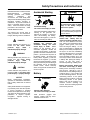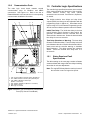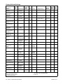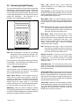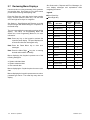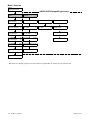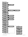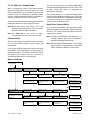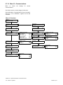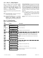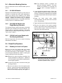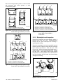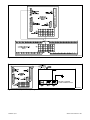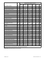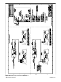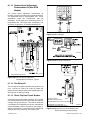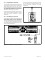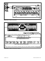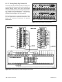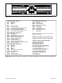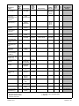
1
Operation
Industrial Generator Sets
Models:
20-3250 kW
Controllers:
Decision-Makerr 550
Software (Code) Version 2.10 or higher
TP-6200 10/12i
California Proposition 65
WARNING
Engine exhaust from this product contains chemicals
known to the State of California to cause cancer, birth
defects, or other reproductive harm.
Product Identification Information
Product identification numbers determine service parts.
Record the product identification numbers in the spaces
below immediately after unpacking the products so that
the numbers are readily available for future reference.
Record field-installed kit numbers after installing the kits.
Generator Set Identification Numbers
Record the product identification numbers from the
generator set nameplate(s).
Record the controller description from the generator set
operation manual, spec sheet, or sales invoice. Record
the Controller Serial Number from the controller
nameplate.
Decision-Makerr 550
Controller Description
Controller Serial Number
Firmware/Software Version Numbers
Model Designation
Specification Number
Serial Number
Accessory Number
Controller Identification
Accessory Description
Record the version and reference numbers as shipped
from the manufacturer. Determine the Application
Program Version Number as shown in Menu 20.
Determine the Personality Profile Reference Number
from the disk supplied with the literature packet.
Application Program Version Number
Personality Profile Reference Number
User Parameter File Reference Number
Version Number Upgrades/Updates
Record the version number upgrade/updates when
installed.
Version No./Date Installed
Version No./Date Installed
Version No./Date Installed
Version No./Date Installed
Version No./Date Installed
Version No./Date Installed
Engine Identification
Record the product identification information from the
engine nameplate.
Manufacturer
Model Designation
Serial Number
Version No./Date Installed
Version No./Date Installed
Software Options
Record the software options.
Number and Description
Number and Description
Number and Description
Table of Contents
Product Identification Information . . . . . . . . . . . . . . . . . . . . . . . . . . . . . . . . . . . . . . . . . . . . . . . . . . . . . . . . . . . . 2
Safety Precautions and Instructions . . . . . . . . . . . . . . . . . . . . . . . . . . . . . . . . . . . . . . . . . . . . . . . . . . . . . . . .
7
Introduction . . . . . . . . . . . . . . . . . . . . . . . . . . . . . . . . . . . . . . . . . . . . . . . . . . . . . . . . . . . . . . . . . . . . . . . . . . . . . . . 13
Abbreviations . . . . . . . . . . . . . . . . . . . . . . . . . . . . . . . . . . . . . . . . . . . . . . . . . . . . . . . . . . . . . . 13
List of Related Materials . . . . . . . . . . . . . . . . . . . . . . . . . . . . . . . . . . . . . . . . . . . . . . . . . . . . . 13
Service Assistance . . . . . . . . . . . . . . . . . . . . . . . . . . . . . . . . . . . . . . . . . . . . . . . . . . . . . . . . . . . . . . . . . . . . . . . . 14
Section 1 Specifications and Features . . . . . . . . . . . . . . . . . . . . . . . . . . . . . . . . . . . . . . . . . . . . . . . . . . . . . .
1.1 Introduction . . . . . . . . . . . . . . . . . . . . . . . . . . . . . . . . . . . . . . . . . . . . . . . . . . . . . . . . . .
1.2 Controller Features . . . . . . . . . . . . . . . . . . . . . . . . . . . . . . . . . . . . . . . . . . . . . . . . . . . .
1.2.1
Annunciator Lamps . . . . . . . . . . . . . . . . . . . . . . . . . . . . . . . . . . . . . . . . . . . .
1.2.2
Digital Display and Keypad . . . . . . . . . . . . . . . . . . . . . . . . . . . . . . . . . . . . .
1.2.3
Switches and Controls . . . . . . . . . . . . . . . . . . . . . . . . . . . . . . . . . . . . . . . . .
1.2.4
Controller Circuit Boards . . . . . . . . . . . . . . . . . . . . . . . . . . . . . . . . . . . . . . .
1.2.5
Fuses . . . . . . . . . . . . . . . . . . . . . . . . . . . . . . . . . . . . . . . . . . . . . . . . . . . . . . .
1.2.6
Terminal Strips and Connectors . . . . . . . . . . . . . . . . . . . . . . . . . . . . . . . . .
1.2.7
Circuit Board Interconnections for Calibration Procedure . . . . . . . . . . . .
1.2.8
Communication Ports . . . . . . . . . . . . . . . . . . . . . . . . . . . . . . . . . . . . . . . . . .
1.3 Controller Logic Specifications . . . . . . . . . . . . . . . . . . . . . . . . . . . . . . . . . . . . . . . . . .
1.3.1
Status Event and Fault Specifications . . . . . . . . . . . . . . . . . . . . . . . . . . . .
1.3.2
Voltage Regulator and Calibration Specifications . . . . . . . . . . . . . . . . . .
1.3.3
Voltage Regulator Adjustments . . . . . . . . . . . . . . . . . . . . . . . . . . . . . . . . . .
15
15
15
16
18
20
21
21
21
22
23
23
23
30
30
Section 2 Operation . . . . . . . . . . . . . . . . . . . . . . . . . . . . . . . . . . . . . . . . . . . . . . . . . . . . . . . . . . . . . . . . . . . . . . .
2.1 Prestart Checklist . . . . . . . . . . . . . . . . . . . . . . . . . . . . . . . . . . . . . . . . . . . . . . . . . . . . .
2.2 Exercising Generator Set . . . . . . . . . . . . . . . . . . . . . . . . . . . . . . . . . . . . . . . . . . . . . . .
2.3 Controller Operation . . . . . . . . . . . . . . . . . . . . . . . . . . . . . . . . . . . . . . . . . . . . . . . . . . .
2.3.1
Starting . . . . . . . . . . . . . . . . . . . . . . . . . . . . . . . . . . . . . . . . . . . . . . . . . . . . . .
2.3.2
Stopping (User Stopping and Fault Shutdown) . . . . . . . . . . . . . . . . . . . .
2.3.3
Emergency Stop Switch Resetting . . . . . . . . . . . . . . . . . . . . . . . . . . . . . . .
2.3.4
Status Lamps . . . . . . . . . . . . . . . . . . . . . . . . . . . . . . . . . . . . . . . . . . . . . . . . .
2.3.5
System Warning Lamp . . . . . . . . . . . . . . . . . . . . . . . . . . . . . . . . . . . . . . . . .
2.3.6
System Shutdown Lamp . . . . . . . . . . . . . . . . . . . . . . . . . . . . . . . . . . . . . . .
2.3.7
Controller Resetting (Following System Shutdown or Warning) . . . . . .
2.4 Menu List Summary . . . . . . . . . . . . . . . . . . . . . . . . . . . . . . . . . . . . . . . . . . . . . . . . . . .
2.5 Reviewing Digital Display . . . . . . . . . . . . . . . . . . . . . . . . . . . . . . . . . . . . . . . . . . . . . .
2.5.1
Keypad Operation . . . . . . . . . . . . . . . . . . . . . . . . . . . . . . . . . . . . . . . . . . . . .
2.5.2
Auto-Scroll Function . . . . . . . . . . . . . . . . . . . . . . . . . . . . . . . . . . . . . . . . . . .
2.5.3
Request and Error Messages . . . . . . . . . . . . . . . . . . . . . . . . . . . . . . . . . . .
2.6 Monitoring and Programming Setup . . . . . . . . . . . . . . . . . . . . . . . . . . . . . . . . . . . . . .
2.6.1
PC Communications . . . . . . . . . . . . . . . . . . . . . . . . . . . . . . . . . . . . . . . . . . .
2.6.2
Modbus Communications . . . . . . . . . . . . . . . . . . . . . . . . . . . . . . . . . . . . . . .
2.7 Reviewing Menu Displays . . . . . . . . . . . . . . . . . . . . . . . . . . . . . . . . . . . . . . . . . . . . . .
2.7.1
Menu 1—Generator Monitoring . . . . . . . . . . . . . . . . . . . . . . . . . . . . . . . . . .
2.7.2
Menu 2—Engine Monitoring . . . . . . . . . . . . . . . . . . . . . . . . . . . . . . . . . . . .
2.7.3
Menu 3—Analog Monitoring . . . . . . . . . . . . . . . . . . . . . . . . . . . . . . . . . . . .
2.7.4
Menu 4—Operational Records . . . . . . . . . . . . . . . . . . . . . . . . . . . . . . . . . .
2.7.5
Menu 5—Event History . . . . . . . . . . . . . . . . . . . . . . . . . . . . . . . . . . . . . . . . .
2.7.6
Menu 6—Time and Date . . . . . . . . . . . . . . . . . . . . . . . . . . . . . . . . . . . . . . .
2.7.7
Menu 7—Generator System . . . . . . . . . . . . . . . . . . . . . . . . . . . . . . . . . . . .
2.7.8
Menu 8—Time Delays . . . . . . . . . . . . . . . . . . . . . . . . . . . . . . . . . . . . . . . . .
2.7.9
Menu 9—Input Setup . . . . . . . . . . . . . . . . . . . . . . . . . . . . . . . . . . . . . . . . . .
2.7.10 Menu 10—Output Setup . . . . . . . . . . . . . . . . . . . . . . . . . . . . . . . . . . . . . . . .
2.7.11 Menu 11—Voltage Regulator . . . . . . . . . . . . . . . . . . . . . . . . . . . . . . . . . . . .
2.7.12 Menu 12—Calibration . . . . . . . . . . . . . . . . . . . . . . . . . . . . . . . . . . . . . . . . . .
33
33
33
33
33
35
35
35
35
38
41
41
47
47
48
48
49
50
51
52
53
55
57
58
59
59
59
61
62
64
66
67
TP-6200 10/12
Table of Contents
3
Table of Contents, continued
2.7.13 Menu 13—Communications . . . . . . . . . . . . . . . . . . . . . . . . . . . . . . . . . . . .
2.7.14 Menu 14—Programming Mode . . . . . . . . . . . . . . . . . . . . . . . . . . . . . . . . . .
2.7.15 Menu 15—Protective Relays (PR) . . . . . . . . . . . . . . . . . . . . . . . . . . . . . . .
2.7.16 Menu 20—Factory Setup (Version 2.10) . . . . . . . . . . . . . . . . . . . . . . . . . .
2.7.17 Menu 20—Factory Setup (Version 2.21) . . . . . . . . . . . . . . . . . . . . . . . . . .
Local Programming Mode On . . . . . . . . . . . . . . . . . . . . . . . . . . . . . . . . . . . . . . . . . . .
2.8.1
Menu 1—Generator Monitoring . . . . . . . . . . . . . . . . . . . . . . . . . . . . . . . . . .
2.8.2
Menu 2—Engine Monitoring . . . . . . . . . . . . . . . . . . . . . . . . . . . . . . . . . . . .
2.8.3
Menu 3—Analog Monitoring . . . . . . . . . . . . . . . . . . . . . . . . . . . . . . . . . . . .
2.8.4
Menu 4—Operational Records . . . . . . . . . . . . . . . . . . . . . . . . . . . . . . . . . .
2.8.5
Menu 5—Event History . . . . . . . . . . . . . . . . . . . . . . . . . . . . . . . . . . . . . . . . .
2.8.6
Menu 6—Time and Date . . . . . . . . . . . . . . . . . . . . . . . . . . . . . . . . . . . . . . .
2.8.7
Menu 7—Generator System . . . . . . . . . . . . . . . . . . . . . . . . . . . . . . . . . . . .
2.8.8
Menu 8—Time Delays . . . . . . . . . . . . . . . . . . . . . . . . . . . . . . . . . . . . . . . . .
2.8.9
Menu 9—Input Setup . . . . . . . . . . . . . . . . . . . . . . . . . . . . . . . . . . . . . . . . . .
2.8.10 Menu 10—Output Setup . . . . . . . . . . . . . . . . . . . . . . . . . . . . . . . . . . . . . . . .
2.8.11 Menu 11—Voltage Regulator . . . . . . . . . . . . . . . . . . . . . . . . . . . . . . . . . . . .
2.8.12 Menu 12—Calibration . . . . . . . . . . . . . . . . . . . . . . . . . . . . . . . . . . . . . . . . . .
2.8.13 Menu 13—Communications . . . . . . . . . . . . . . . . . . . . . . . . . . . . . . . . . . . .
2.8.14 Menu 14—Programming Mode . . . . . . . . . . . . . . . . . . . . . . . . . . . . . . . . . .
2.8.15 Menu 15—Protective Relays (PR) . . . . . . . . . . . . . . . . . . . . . . . . . . . . . . .
2.8.16 Menu 20—Factory Setup . . . . . . . . . . . . . . . . . . . . . . . . . . . . . . . . . . . . . . .
68
69
70
71
72
74
75
79
83
86
88
89
90
96
98
104
114
120
125
129
131
135
Section 3 Scheduled Maintenance . . . . . . . . . . . . . . . . . . . . . . . . . . . . . . . . . . . . . . . . . . . . . . . . . . . . . . . . . .
3.1 Alternator Service . . . . . . . . . . . . . . . . . . . . . . . . . . . . . . . . . . . . . . . . . . . . . . . . . . . . .
3.2 Engine Service . . . . . . . . . . . . . . . . . . . . . . . . . . . . . . . . . . . . . . . . . . . . . . . . . . . . . . .
3.3 Service Schedule . . . . . . . . . . . . . . . . . . . . . . . . . . . . . . . . . . . . . . . . . . . . . . . . . . . . .
3.4 Alternator Bearing Service . . . . . . . . . . . . . . . . . . . . . . . . . . . . . . . . . . . . . . . . . . . . . .
3.4.1
20--300 kW Models . . . . . . . . . . . . . . . . . . . . . . . . . . . . . . . . . . . . . . . . . . . .
3.4.2
300--2250 kW Models with Single-Bearing Alternator . . . . . . . . . . . . . . .
3.4.3
1250 kW and Larger Models with Two-Bearing Alternator . . . . . . . . . . .
3.5 Diesel Fuel Systems . . . . . . . . . . . . . . . . . . . . . . . . . . . . . . . . . . . . . . . . . . . . . . . . . . .
3.5.1
Bleeding Air from Fuel System . . . . . . . . . . . . . . . . . . . . . . . . . . . . . . . . . .
3.5.2
Subbase Fuel Day Tank Electronic Control Module (ECM) . . . . . . . . . .
3.5.3
Subbase Inner Fuel Tank Alarm . . . . . . . . . . . . . . . . . . . . . . . . . . . . . . . . .
3.6 Gas Fuel Systems (REZG_ and REZX_/RZX_ models) . . . . . . . . . . . . . . . . . . . . .
3.6.1
Gas Fuel System Concept (Single Fuel) . . . . . . . . . . . . . . . . . . . . . . . . . .
3.6.2
LPG Liquid Withdrawal Fuel System Concept . . . . . . . . . . . . . . . . . . . . .
3.6.3
Natural Gas and LPG Conversion . . . . . . . . . . . . . . . . . . . . . . . . . . . . . . .
3.6.4
Fuel System Changeover Kits (Dual Fuel) . . . . . . . . . . . . . . . . . . . . . . . .
3.6.5
Crankcase Ventilation (CCV) Heater Kit GM78171-KP1
(125/150REZG models) . . . . . . . . . . . . . . . . . . . . . . . . . . . . . . . . . . . . . . . .
3.7 Cooling System . . . . . . . . . . . . . . . . . . . . . . . . . . . . . . . . . . . . . . . . . . . . . . . . . . . . . . .
3.7.1
Coolant Level Check . . . . . . . . . . . . . . . . . . . . . . . . . . . . . . . . . . . . . . . . . . .
3.7.2
Cooling System Component Inspection . . . . . . . . . . . . . . . . . . . . . . . . . . .
3.7.3
Procedure to Drain Cooling System . . . . . . . . . . . . . . . . . . . . . . . . . . . . . .
3.7.4
Procedure to Flush and Clean Cooling System . . . . . . . . . . . . . . . . . . . .
3.7.5
Procedure to Refill Cooling System . . . . . . . . . . . . . . . . . . . . . . . . . . . . . .
3.8 Radiator Fan Bolt Retorque . . . . . . . . . . . . . . . . . . . . . . . . . . . . . . . . . . . . . . . . . . . . .
3.9 Radiator Expansion Joint Loosening—Initial Setup Only . . . . . . . . . . . . . . . . . . . .
3.10 Radiator Fan Bearing Lubrication . . . . . . . . . . . . . . . . . . . . . . . . . . . . . . . . . . . . . . . .
3.11 Battery . . . . . . . . . . . . . . . . . . . . . . . . . . . . . . . . . . . . . . . . . . . . . . . . . . . . . . . . . . . . . . .
3.11.1 Clean Battery . . . . . . . . . . . . . . . . . . . . . . . . . . . . . . . . . . . . . . . . . . . . . . . . .
3.11.2 Electrolyte Level Inspection . . . . . . . . . . . . . . . . . . . . . . . . . . . . . . . . . . . . .
3.11.3 Specific Gravity Check . . . . . . . . . . . . . . . . . . . . . . . . . . . . . . . . . . . . . . . . .
3.11.4 Charge Battery . . . . . . . . . . . . . . . . . . . . . . . . . . . . . . . . . . . . . . . . . . . . . . . .
137
137
137
138
140
140
140
140
140
140
141
142
142
142
142
143
143
2.8
4
Table of Contents
145
145
145
146
146
146
146
147
148
148
149
149
150
151
151
TP-6200 10/12
Table of Contents, continued
3.12 Detroit Diesel Engine Control Systems . . . . . . . . . . . . . . . . . . . . . . . . . . . . . . . . . . .
3.12.1 Features . . . . . . . . . . . . . . . . . . . . . . . . . . . . . . . . . . . . . . . . . . . . . . . . . . . . .
3.12.2 DDEC Engine Diagnostics . . . . . . . . . . . . . . . . . . . . . . . . . . . . . . . . . . . . . .
3.13 Engine Control Systems . . . . . . . . . . . . . . . . . . . . . . . . . . . . . . . . . . . . . . . . . . . . . . . .
3.14 Storage Procedure . . . . . . . . . . . . . . . . . . . . . . . . . . . . . . . . . . . . . . . . . . . . . . . . . . . .
3.14.1 Lubricating System . . . . . . . . . . . . . . . . . . . . . . . . . . . . . . . . . . . . . . . . . . . .
3.14.2 Cooling System . . . . . . . . . . . . . . . . . . . . . . . . . . . . . . . . . . . . . . . . . . . . . . .
3.14.3 Fuel System . . . . . . . . . . . . . . . . . . . . . . . . . . . . . . . . . . . . . . . . . . . . . . . . . .
3.14.4 Internal Engine Components (Gas-Fueled Engines) . . . . . . . . . . . . . . . .
3.14.5 Exterior . . . . . . . . . . . . . . . . . . . . . . . . . . . . . . . . . . . . . . . . . . . . . . . . . . . . . .
3.14.6 Battery . . . . . . . . . . . . . . . . . . . . . . . . . . . . . . . . . . . . . . . . . . . . . . . . . . . . . . .
152
152
152
153
153
153
153
154
154
154
154
Section 4 General Troubleshooting . . . . . . . . . . . . . . . . . . . . . . . . . . . . . . . . . . . . . . . . . . . . . . . . . . . . . . . . . 155
4.1 General Troubleshooting Chart . . . . . . . . . . . . . . . . . . . . . . . . . . . . . . . . . . . . . . . . . . 156
4.2 Controller Display and Voltage Regulation Troubleshooting Chart . . . . . . . . . . . . 159
Section 5 Generator Set Reconnection . . . . . . . . . . . . . . . . . . . . . . . . . . . . . . . . . . . . . . . . . . . . . . . . . . . . . 161
5.1 Introduction . . . . . . . . . . . . . . . . . . . . . . . . . . . . . . . . . . . . . . . . . . . . . . . . . . . . . . . . . . 161
5.2 Voltage Reconnection Procedure . . . . . . . . . . . . . . . . . . . . . . . . . . . . . . . . . . . . . . . . 162
Section 6 Accessories . . . . . . . . . . . . . . . . . . . . . . . . . . . . . . . . . . . . . . . . . . . . . . . . . . . . . . . . . . . . . . . . . . . . .
6.1 Accessories and Connections . . . . . . . . . . . . . . . . . . . . . . . . . . . . . . . . . . . . . . . . . . .
6.1.1
Audiovisual Alarm Kit . . . . . . . . . . . . . . . . . . . . . . . . . . . . . . . . . . . . . . . . . .
6.1.2
Common Failure Relay Kit . . . . . . . . . . . . . . . . . . . . . . . . . . . . . . . . . . . . . .
6.1.3
Controller (Customer) Connection Kit . . . . . . . . . . . . . . . . . . . . . . . . . . . .
6.1.4
Float/Equalize Battery Charger Kit with Alarm Option . . . . . . . . . . . . . . .
6.1.5
Ground Fault Annunciation . . . . . . . . . . . . . . . . . . . . . . . . . . . . . . . . . . . . .
6.1.6
Idle (Speed) Mode Feature . . . . . . . . . . . . . . . . . . . . . . . . . . . . . . . . . . . . .
6.1.7
Low Fuel (Level/Pressure) Switch . . . . . . . . . . . . . . . . . . . . . . . . . . . . . . .
6.1.8
Prime Power Switch Kit . . . . . . . . . . . . . . . . . . . . . . . . . . . . . . . . . . . . . . . .
6.1.9
Remote Emergency Stop Kit . . . . . . . . . . . . . . . . . . . . . . . . . . . . . . . . . . . .
6.1.10 Remote Reset Feature . . . . . . . . . . . . . . . . . . . . . . . . . . . . . . . . . . . . . . . . .
6.1.11 Remote Serial Annunciator . . . . . . . . . . . . . . . . . . . . . . . . . . . . . . . . . . . . .
6.1.12 Remote Speed Adjustment Potentiometer Kit (Non-ECM Models) . . . .
6.1.13 Run Relay Kit . . . . . . . . . . . . . . . . . . . . . . . . . . . . . . . . . . . . . . . . . . . . . . . . .
6.1.14 Shunt-Trip Line Circuit Breaker . . . . . . . . . . . . . . . . . . . . . . . . . . . . . . . . . .
6.1.15 Single-Relay Dry Contact Kit . . . . . . . . . . . . . . . . . . . . . . . . . . . . . . . . . . . .
6.1.16 Ten-Relay Dry Contact Kit . . . . . . . . . . . . . . . . . . . . . . . . . . . . . . . . . . . . . .
6.1.17 Twenty-Relay Dry Contact Kit . . . . . . . . . . . . . . . . . . . . . . . . . . . . . . . . . . .
6.1.18 Wireless Monitor . . . . . . . . . . . . . . . . . . . . . . . . . . . . . . . . . . . . . . . . . . . . . .
6.2 Accessory Connections . . . . . . . . . . . . . . . . . . . . . . . . . . . . . . . . . . . . . . . . . . . . . . . .
167
167
167
168
168
168
170
171
172
172
173
173
174
181
181
181
182
182
184
185
186
Appendix A Abbreviations . . . . . . . . . . . . . . . . . . . . . . . . . . . . . . . . . . . . . . . . . . . . . . . . . . . . . . . . . . . . . . . . 193
Appendix B User-Defined Settings . . . . . . . . . . . . . . . . . . . . . . . . . . . . . . . . . . . . . . . . . . . . . . . . . . . . . . . . 195
Appendix C Voltage Regulator Definitions and Adjustments . . . . . . . . . . . . . . . . . . . . . . . . . . . . . . . . . 202
Appendix D Alternator Protection . . . . . . . . . . . . . . . . . . . . . . . . . . . . . . . . . . . . . . . . . . . . . . . . . . . . . . . . . 208
Appendix E Inputs and System Events by Application . . . . . . . . . . . . . . . . . . . . . . . . . . . . . . . . . . . . . . 209
TP-6200 10/12
Table of Contents
5
Notes
6
TP-6200 10/12
Safety Precautions and Instructions
IMPORTANT SAFETY INSTRUCTIONS.
Electromechanical
equipment,
including generator sets, transfer
switches,
switchgear,
and
accessories, can cause bodily harm
and pose life-threatening danger when
improperly installed, operated, or
maintained. To prevent accidents be
aware of potential dangers and act
safely. Read and follow all safety
precautions and instructions. SAVE
THESE INSTRUCTIONS.
This manual has several types of
safety precautions and instructions:
Danger, Warning, Caution, and Notice.
Accidental Starting
WARNING
Accidental starting.
Can cause severe injury or death.
Disconnect the battery cables before
working on the generator set.
Remove the negative (--) lead first
when disconnecting the battery.
Reconnect the negative (--) lead last
when reconnecting the battery.
DANGER
Danger indicates the presence of a
hazard that will cause severe
personal
injury,
death,
or
substantial property damage.
WARNING
Warning indicates the presence of a
hazard that can cause severe
personal
injury,
death,
or
substantial property damage.
CAUTION
Caution indicates the presence of a
hazard that will or can cause minor
personal injury or property damage.
Disabling
the
generator set.
Accidental starting can cause
severe injury or death.
Before
working on the generator set or
connected equipment, disable the
generator set as follows: (1) Move the
generator set master switch to the OFF
position. (2) Disconnect the power to
the battery charger. (3) Remove the
battery cables, negative (--) lead first.
Reconnect the negative (--) lead last
when reconnecting the battery. Follow
these precautions to prevent starting of
the generator set by an automatic
transfer switch, remote start/stop
switch, or engine start command from a
remote computer.
Battery
NOTICE
Notice communicates installation,
operation, or maintenance information
that is safety related but not hazard
related.
Safety decals affixed to the equipment
in prominent places alert the operator
or service technician to potential
hazards and explain how to act safely.
The decals are shown throughout this
publication to improve operator
recognition.
Replace missing or
damaged decals.
TP-6200 10/12
WARNING
WARNING
Explosion.
Can cause severe injury or death.
Relays in the battery charger
cause arcs or sparks.
Locate the battery in a well-ventilated
area. Isolate the battery charger from
explosive fumes.
Battery electrolyte is a diluted
sulfuric acid.
Battery acid can
cause severe injury or death. Battery
acid can cause blindness and burn
skin. Always wear splashproof safety
goggles, rubber gloves, and boots
when servicing the battery. Do not
open a sealed battery or mutilate the
battery case. If battery acid splashes in
the eyes or on the skin, immediately
flush the affected area for 15 minutes
with large quantities of clean water.
Seek immediate medical aid in the
case of eye contact. Never add acid to
a battery after placing the battery in
service, as this may result in
hazardous spattering of battery acid.
Battery acid cleanup. Battery acid
can cause severe injury or death.
Battery acid is electrically conductive
and corrosive. Add 500 g (1 lb.) of
bicarbonate of soda (baking soda) to a
container with 4 L (1 gal.) of water and
mix the neutralizing solution. Pour the
neutralizing solution on the spilled
battery acid and continue to add the
neutralizing solution to the spilled
battery acid until all evidence of a
chemical reaction (foaming) has
ceased. Flush the resulting liquid with
water and dry the area.
Sulfuric acid in batteries.
Can cause severe injury or death.
Wear protective goggles and
clothing. Battery acid may cause
blindness and burn skin.
Safety Precautions and Instructions
7
Battery gases. Explosion can cause
severe injury or death. Battery gases
can cause an explosion. Do not smoke
or permit flames or sparks to occur
near a battery at any time, particularly
when it is charging. Do not dispose of a
battery in a fire. To prevent burns and
sparks that could cause an explosion,
avoid touching the battery terminals
with tools or other metal objects.
Remove all jewelry before servicing
the equipment.
Discharge static
electricity from your body before
touching batteries by first touching a
grounded metal surface away from the
battery. To avoid sparks, do not disturb
the battery charger connections while
the battery is charging. Always turn the
battery
charger
off
before
disconnecting the battery connections.
Ventilate the compartments containing
batteries to prevent accumulation of
explosive gases.
Battery short circuits. Explosion
can cause severe injury or death.
Short circuits can cause bodily injury
and/or
equipment
damage.
Disconnect
the
battery
before
generator
set
installation
or
maintenance. Remove all jewelry
before servicing the equipment. Use
tools with insulated handles. Remove
the negative (--) lead first when
disconnecting the battery. Reconnect
the negative (--) lead last when
reconnecting the battery.
Never
connect the negative (--) battery cable
to the positive (+) connection terminal
of the starter solenoid. Do not test the
battery condition by shorting the
terminals together.
Engine Backfire/Flash
Fire
WARNING
Fire.
Can cause severe injury or death.
Do not smoke or permit flames or
sparks near fuels or the fuel system.
8
Safety Precautions and Instructions
Servicing the fuel system. A flash
fire can cause severe injury or
death. Do not smoke or permit flames
or sparks near the carburetor, fuel line,
fuel filter, fuel pump, or other potential
sources of spilled fuels or fuel vapors.
Catch fuels in an approved container
when removing the fuel line or
carburetor.
Servicing the air cleaner. A sudden
backfire can cause severe injury or
death. Do not operate the generator
set with the air cleaner removed.
Combustible materials. A fire can
cause severe injury or death.
Generator set engine fuels and fuel
vapors are flammable and explosive.
Handle these materials carefully to
minimize the risk of fire or explosion.
Equip the compartment or nearby area
with a fully charged fire extinguisher.
Select a fire extinguisher rated ABC or
BC for electrical fires or as
recommended by the local fire code or
an authorized agency.
Train all
personnel
on
fire extinguisher
operation
and
fire
prevention
procedures.
Carbon
monoxide
symptoms.
Carbon monoxide can cause severe
nausea, fainting, or death. Carbon
monoxide is a poisonous gas present
in exhaust gases. Carbon monoxide is
an odorless, colorless, tasteless,
nonirritating gas that can cause death if
inhaled for even a short time. Carbon
monoxide
poisoning
symptoms
include but are not limited to the
following:
D Light-headedness, dizziness
D Physical fatigue, weakness in
joints and muscles
D Sleepiness, mental fatigue,
inability to concentrate
or speak clearly, blurred vision
D Stomachache, vomiting, nausea
If experiencing any of these symptoms
and carbon monoxide poisoning is
possible, seek fresh air immediately
and remain active. Do not sit, lie down,
or fall asleep. Alert others to the
possibility of carbon monoxide
poisoning. Seek medical attention if
the condition of affected persons does
not improve within minutes of breathing
fresh air.
Fuel System
Exhaust System
WARNING
Carbon monoxide.
Can cause severe
fainting, or death.
nausea,
The exhaust system must be
leakproof and routinely inspected.
WARNING
Explosive fuel vapors.
Can cause severe injury or death.
Use extreme care when handling,
storing, and using fuels.
Generator set operation. Carbon
monoxide can cause severe
nausea, fainting, or death. Carbon
monoxide is an odorless, colorless,
tasteless, nonirritating gas that can
cause death if inhaled for even a short
time. Avoid breathing exhaust fumes
when working on or near the generator
set. Never operate the generator set
inside a building unless the exhaust
gas is piped safely outside. Never
operate the generator set where
exhaust gas could accumulate and
seep back inside a potentially occupied
building.
TP-6200 10/12
The fuel system. Explosive fuel
vapors can cause severe injury or
death. Vaporized fuels are highly
explosive. Use extreme care when
handling and storing fuels. Store fuels
in a well-ventilated area away from
spark-producing equipment and out of
the reach of children. Never add fuel to
the tank while the engine is running
because spilled fuel may ignite on
contact with hot parts or from sparks.
Do not smoke or permit flames or
sparks to occur near sources of spilled
fuel or fuel vapors. Keep the fuel lines
and connections tight and in good
condition. Do not replace flexible fuel
lines with rigid lines. Use flexible
sections to avoid fuel line breakage
caused by vibration. Do not operate
the generator set in the presence of
fuel leaks, fuel accumulation, or
sparks. Repair fuel systems before
resuming generator set operation.
Explosive fuel vapors can cause
severe injury or death.
Take
additional precautions when using the
following fuels:
Gasoline—Store gasoline only in
approved red containers clearly
marked GASOLINE.
Propane (LP)—Adequate ventilation
is mandatory. Because propane is
heavier than air, install propane gas
detectors low in a room. Inspect the
detectors per the manufacturer’s
instructions.
Natural Gas—Adequate ventilation is
mandatory. Because natural gas rises,
install natural gas detectors high in a
room. Inspect the detectors per the
manufacturer’s instructions.
Fuel tanks. Explosive fuel vapors
can cause severe injury or death.
Gasoline and other volatile fuels stored
in day tanks or subbase fuel tanks can
cause an explosion. Store only diesel
fuel in tanks.
Draining the fuel system. Explosive
fuel vapors can cause severe injury
or death. Spilled fuel can cause an
explosion. Use a container to catch
fuel when draining the fuel system.
Wipe up spilled fuel after draining the
system.
TP-6200 10/12
Gas fuel leaks.
Explosive fuel
vapors can cause severe injury or
death. Fuel leakage can cause an
explosion. Check the LP vapor gas or
natural gas fuel system for leakage by
using a soap and water solution with
the fuel system test pressurized to
6--8 ounces
per
square
inch
(10--14 inches water column). Do not
use a soap solution containing either
ammonia or chlorine because both
prevent bubble formation.
A
successful test depends on the ability
of the solution to bubble.
LP liquid withdrawal fuel leaks.
Explosive fuel vapors can cause
severe injury or death. Fuel leakage
can cause an explosion. Check the LP
liquid withdrawal gas fuel system for
leakage by using a soap and water
solution with the fuel system test
pressurized to at least 90 psi
(621 kPa). Do not use a soap solution
containing either ammonia or chlorine
because
both
prevent
bubble
formation. A successful test depends
on the ability of the solution to bubble.
Hazardous Voltage/
Moving Parts
DANGER
Hazardous voltage.
Will cause severe injury or death.
Disconnect all power sources before
opening the enclosure.
WARNING
Hazardous voltage. Moving parts.
Can cause severe injury or death.
Operate the generator set only when
all guards and electrical enclosures
are in place.
Hazardous Noise
WARNING
CAUTION
Hazardous noise.
Can cause hearing loss.
Never operate the generator set
without a muffler or with a faulty
exhaust system.
Engine noise. Hazardous noise can
cause hearing loss. Generator sets
not equipped with sound enclosures
can produce noise levels greater than
105 dBA.
Prolonged exposure to
noise levels greater than 85 dBA can
cause permanent hearing loss. Wear
hearing protection when near an
operating generator set.
Hazardous voltage.
Backfeed to the utility system can
cause property damage, severe
injury, or death.
If the generator set is used for
standby power, install an automatic
transfer switch to prevent inadvertent
interconnection of standby and
normal sources of supply.
Grounding electrical equipment.
Hazardous voltage can cause
severe injury or death. Electrocution
is possible whenever electricity is
present. Ensure you comply with all
applicable codes and standards.
Electrically ground the generator set,
transfer switch, and related equipment
and electrical circuits. Turn off the
main circuit breakers of all power
sources
before
servicing
the
equipment. Never contact electrical
leads or appliances when standing in
water or on wet ground because these
conditions increase the risk of
electrocution.
Safety Precautions and Instructions
9
High voltage test.
Hazardous
voltage can cause severe injury or
death. Follow the instructions of the
test equipment manufacturer when
performing high-voltage tests on the
rotor or stator. An improper test
procedure can damage equipment or
lead to generator set failure.
Testing the photo transistor circuit
board.
Hazardous voltage can
cause severe injury or death. When
the end cover is removed, do not
expose the photo transistor circuit
board mounted on the generator set
end bracket to any external light
source, as exposure to light causes
high voltage. Keep foreign sources of
light away from the photo transistor
circuit board during testing. Place
black electrical tape over the LED on
the circuit board before starting the
generator set.
Installing the photo transistor
circuit board. Hazardous voltage
can cause severe injury or death.
Ensure that the foil side of the photo
transistor circuit board, the end of the
shaft, and the threaded holes are clean
and free of metal particles and chips.
Metal debris may short-circuit the
photo transistor circuit board and
cause hazardous voltage in the
generator set. Do not reconnect the
generator set to the load until the AC
voltmeter shows the correct output.
Installing the battery charger.
Hazardous voltage can cause
severe injury or death.
An
ungrounded battery charger may
cause electrical shock. Connect the
battery charger enclosure to the
ground of a permanent wiring system.
As an alternative, install an equipment
grounding conductor with circuit
conductors and connect it to the
equipment grounding terminal or the
lead on the battery charger. Install the
battery charger as prescribed in the
equipment manual. Install the battery
charger in compliance with local codes
and ordinances.
Connecting the battery and the
battery charger. Hazardous voltage
can cause severe injury or death.
Reconnect the battery correctly,
positive to positive and negative to
negative, to avoid electrical shock and
damage to the battery charger and
battery(ies).
Have a qualified
electrician install the battery(ies).
10
Safety Precautions and Instructions
Servicing the day tank. Hazardous
voltage can cause severe injury or
death. Service the day tank electrical
control module (ECM) as prescribed in
the equipment manual. Disconnect the
power to the day tank before servicing.
Press the day tank ECM OFF
pushbutton to disconnect the power.
Notice that line voltage is still present
within the ECM when the POWER ON
light is lit. Ensure that the generator set
and day tank are electrically grounded.
Do not operate the day tank when
standing in water or on wet ground
because these conditions increase the
risk of electrocution.
Short
circuits.
Hazardous
voltage/current can cause severe
injury or death. Short circuits can
cause bodily injury and/or equipment
damage. Do not contact electrical
connections with tools or jewelry while
making adjustments or repairs.
Remove all jewelry before servicing
the equipment.
Engine block heater. Hazardous
voltage can cause severe injury or
death. The engine block heater can
cause electrical shock. Remove the
engine block heater plug from the
electrical outlet before working on the
block heater electrical connections.
Handling the capacitor. Hazardous
voltage can cause severe injury or
death. Electrical shock results from
touching the charged capacitor
terminals. Discharge the capacitor by
shorting the terminals together.
(Capacitor-excited models only)
Electrical backfeed to the utility.
Hazardous backfeed voltage can
cause severe injury or death. Install
a transfer switch in standby power
installations to prevent the connection
of standby and other sources of power.
Electrical backfeed into a utility
electrical system can cause severe
injury or death to utility personnel
working on power lines.
Testing live electrical circuits.
Hazardous voltage or current can
cause severe injury or death. Have
trained and qualified personnel take
diagnostic measurements of live
circuits. Use adequately rated test
equipment with electrically insulated
probes and follow the instructions of
the test equipment manufacturer when
performing voltage tests. Observe the
following precautions when performing
voltage tests: (1) Remove all jewelry.
(2) Stand on a dry, approved
electrically insulated mat. (3) Do not
touch the enclosure or components
inside the enclosure. (4) Be prepared
for the system to operate automatically.
(600 volts and under)
WARNING
Airborne particles.
Can cause severe
blindness.
injury
or
Wear protective goggles and clothing
when using power tools, hand tools,
or compressed air.
Servicing the generator set when it
is operating. Exposed moving parts
can cause severe injury or death.
Keep hands, feet, hair, clothing, and
test leads away from the belts and
pulleys when the generator set is
running. Replace guards, screens,
and covers before operating the
generator set.
Heavy Equipment
WARNING
Unbalanced weight.
Improper lifting can cause severe
injury or death and equipment
damage.
Do not use lifting eyes.
Lift the generator set using lifting bars
inserted through the lifting holes on
the skid.
TP-6200 10/12
Hot Parts
WARNING
Notice
NOTICE
This generator set has been
rewired from its nameplate voltage
to
Hot coolant and steam.
Can cause severe injury or death.
Before removing the pressure cap,
stop the generator set and allow it to
cool. Then loosen the pressure cap
to relieve pressure.
WARNING
Hot engine and exhaust system.
Can cause severe injury or death.
Do not work on the generator set until
it cools.
Servicing the alternator. Hot parts
can cause severe injury or death.
Avoid touching the alternator field or
exciter armature. When shorted, the
alternator field and exciter armature
become hot enough to cause severe
burns.
246242
NOTICE
Voltage reconnection. Affix a notice
to the generator set after reconnecting
the set to a voltage different from the
voltage on the nameplate. Order
voltage reconnection decal 246242
from
an
authorized
service
distributor/dealer.
NOTICE
Canadian installations only. For
standby service connect the output of
the generator set to a suitably rated
transfer switch in accordance with
Canadian Electrical Code, Part 1.
Servicing the exhaust system. Hot
parts can cause severe injury or
death. Do not touch hot engine parts.
The engine and exhaust system
components become extremely hot
during operation.
TP-6200 10/12
Safety Precautions and Instructions
11
Notes
12
Safety Precautions and Instructions
TP-6200 10/12
Introduction
This manual provides operation instructions for 20 kW
and larger generator sets equipped with the following
controller:
D Decisionr 550, Software (Code) Version 2.10 or
higher
Version 2.10 refers to the controller application software.
To determine the generator set controller software
version, go to Menu 20—Factory Setup and scroll down
to Code Version. The code version is the controller
software version.
Wiring diagram manuals are available separately. Refer
to the engine operation manual for generator set engine
scheduled maintenance information.
Information in this publication represents data available
at the time of print. Kohler Co. reserves the right to
change this publication and the products represented
without notice and without any obligation or liability
whatsoever.
Read this manual and carefully follow all procedures and
safety precautions to ensure proper equipment
operation and to avoid bodily injury. Read and follow the
Safety Precautions and Instructions section at the
beginning of this manual. Keep this manual with the
equipment for future reference.
The equipment service requirements are very important
to safe and efficient operation. Inspect the parts often
and perform required service at the prescribed intervals.
Maintenance work must be performed by appropriately
skilled and suitably trained maintenance personnel
familiar with generator set operation and service.
The disk supplied with this generator set is a backup
copy of the generator set personality program
containing data specific to the engine and alternator.
The engine and alternator data was preprogrammed in
the controller at the factory and no further use of the disk
should be necessary.
Typically, your authorized
distributor stores this disk for possible future use such as
controller replacement or other circumstances requiring
a backup.
Abbreviations
This publication makes use of numerous abbreviations.
Typically, the word(s) are spelled out along with the
abbreviation in parentheses when shown for the first
time in a section. Appendix A, Abbreviations, also
includes many abbreviation definitions.
List of Related Materials
Separate literature contains communication and
software information not provided in this manual.
Figure 1 lists the available literature part numbers.
Communication and Software
Manual Description
550 Controller Spec Sheet
Generator Set/Controller
Wiring Diagram Manual
550 Communications Spec Sheet
Monitor III Converters, Connections,
and Controller Setup
Literature Part No.
G6-46
Multiple Part Numbers
Contact your
Distributor/Dealer
G6-50
TT-1405
Monitor III Software Spec Sheet
G6-76
Monitor III Converter,
Modbusr/Ethernet Spec Sheet
G6-79
Monitor III Software Operation Manual
TP-6347
Modbusr Communications Protocol
Operation Manual
TP-6113
Setup and Application Manual
TP-6140
Service Parts Controllers
TP-6780
Program Loader Software Installation
TT-1285
SiteTecht Software Operation Manual
TP-6701
Remote Serial Annunciator (RSA)
TT-1377
Remote Serial Annunciator (RSA II)
TT-1485
Controller Service Replacement
TT-1310
Figure 1
Related Literature
Modbusr is a registered trademark of Schneider Electric.
TP-6200 10/12
Introduction
13
Service Assistance
For professional advice on generator set power
requirements and conscientious service, please contact
your nearest Kohler distributor or dealer.
D Consult the Yellow Pages under the heading
Generators—Electric.
D Visit
the Kohler Power Systems website at
KohlerPower.com.
D Look at the labels and stickers on your Kohler product
or review the appropriate literature or documents
included with the product.
D Call toll free in the US and Canada 1-800-544-2444.
D Outside the US and Canada, call the nearest regional
office.
Headquarters Europe, Middle East, Africa
(EMEA)
Kohler Power Systems
3 rue de Brennus
93200 Saint Denis
France
Phone: (33) 1 49 178300
Fax: (33) 1 49 178301
Asia Pacific
Power Systems Asia Pacific Regional Office
Singapore, Republic of Singapore
Phone: (65) 6264-6422
Fax: (65) 6264-6455
14
Service Assistance
China
North China Regional Office, Beijing
Phone: (86) 10 6518 7950
(86) 10 6518 7951
(86) 10 6518 7952
Fax: (86) 10 6518 7955
East China Regional Office, Shanghai
Phone: (86) 21 6288 0500
Fax: (86) 21 6288 0550
India, Bangladesh, Sri Lanka
India Regional Office
Bangalore, India
Phone: (91) 80 3366208
(91) 80 3366231
Fax: (91) 80 3315972
Japan, Korea
North Asia Regional Office
Tokyo, Japan
Phone: (813) 3440-4515
Fax: (813) 3440-2727
Latin America
Latin America Regional Office
Lakeland, Florida, USA
Phone: (863) 619-7568
Fax: (863) 701-7131
TP-6200 10/12
Section 1 Specifications and Features
The controller features, accessories, and menu displays
depend upon the engine electronic control module
(ECM) setup and features. Controller features apply to
generator set models with ECM and non-ECM engines
unless otherwise noted.
1.1 Introduction
The spec sheets for each generator set provide modelspecific generator and engine information.
The
controller spec sheet provides specifications for this
controller. Refer to the respective spec sheet for data
not supplied in this manual. Consult the generator set
service manual, installation manual, engine operation
manual, and engine service manual for additional
specifications.
Note: Press any key on the keypad to turn on the
controller lights and display. The lights and
display turn off 5 minutes after the last keypad
entry.
Note: Measurements display in metric or English. Use
Menu 7—Generator System to change the
measurement display.
1.2 Controller Features
The controller features include the annunciator lamps,
digital display and keypad, switches and controls, and
fuses and terminal strip. The following paragraphs detail
the features by general topics.
1
2
3
See Figure 1-1 for an illustration of the controller front
panel. See Figure 1-2 for an illustration of the controller
with the keyswitch option.
4
5
6
TP-6083-2
7
8
1.
2.
3.
4.
Emergency stop switch
Alarm horn (see keypad for alarm silence)
Annunciator lamps (see keypad for lamp test)
Generator set master switch, run/off-reset/auto positions
Figure 1-1
5.
6.
7.
8.
Digital display
Keypad
Operating guide
Controller terminal strips (on circuit board)
550 Controller with Three-Position Selector Switch
TP-6200 10/12
Section 1 Specifications and Features
15
1
2
3
4
5
6
TP-6083-2
7
8
1. Generator set master switch, run/off-reset/auto positions
(keyswitch option)
2. Emergency stop switch
3. Alarm horn (see keypad for alarm silence)
4. Annunciator lamps (see keypad for lamp test)
Figure 1-2
1.2.1
5.
6.
7.
8.
Digital display
Keypad
Operating guide
Controller terminal strips (on circuit board)
550 Controller with Keyswitch Option
Annunciator Lamps
Five annunciator lamps provide visual generator set
status. See Figure 1-3.
Programming Mode.
Yellow programming lamp
indicates the user selected programming mode. See
Figure 1-4.
Programming Lamp
Programming Mode Selection
Lamp Flashing
Local Programming
Lamp Steady On
Remote Programming
Lamp Off
Programming Disabled
Figure 1-4
Programming Lamp Mode
TP-6083-2
Figure 1-3
Annunciator Lamps
System Ready. Green lamp illuminates when the
generator set master switch is in the AUTO (automatic
start) position and the system senses no faults. The unit
is ready to start.
Note: Find additional information for the programming
mode lamp function and access to the local or
remote programming modes in Section 2.8, Local
Programming Mode On, Menu 14—Programming
Mode.
Not in Auto (NIA). Yellow lamp illuminates when the
generator set master switch is not in the AUTO
(automatic start) position.
16
Section 1 Specifications and Features
TP-6200 10/12
System Warning. Yellow lamp identifies an existing
fault condition that does not shut down the generator set.
A continuing system warning fault condition may cause
a system shutdown. Correct all system warnings as
soon as practical.
System Shutdown. Red lamp indicates that the
generator set has shut down because of a fault
condition. The unit will not start without resetting the
controller, see Section 2.3.7, Controller Reset
Procedure.
See Section 2.3.5, System Warning Lamp, for
definitions of the items listed.
See Section 2.3.6, System Shutdown Lamp, for
definitions of the items listed.
The following conditions cause a system warning:
D Engine functions:
d ECM yellow alarm
d
d
d
d
d
d
d
d
d
(DDC/MTU engine with MDEC/ADEC)
High battery voltage
High coolant temperature
Low battery voltage
Low coolant temperature
Low fuel (level or pressure)*
Low oil pressure
Speed sensor fault
Starting aid (system status)
Weak battery
D General functions:
d Auxiliary—Analog up to 7 user-selectable inputs
d
d
d
d
d
d
d
d
d
d
each with a high and low programmable warning
level
Auxiliary—Digital up to 21 user-selectable
warnings
Battery charger fault*
Emergency power system (EPS) supplying load
Engine cooldown delay
Engine start delay
Load shed kW overload
Load shed underfrequency
Master switch not in AUTO (automatic start)
position
NFPA 110 fault (National Fire Protection
Association)
System ready (system status)
D Alternator functions:
d AC sensing loss
d Ground fault*
d Overcurrent
* Requires optional input sensors.
Note: See Figure 2-8 in User Inputs for factoryreserved analog and digital inputs that are not
user-selectable.
TP-6200 10/12
The following conditions cause a system shutdown:
D Engine functions:
d Air damper closed (status), if equipped
d Coolant temperature signal loss
d ECM red alarm
d
d
d
d
d
d
d
d
(DDC/MTU engine with MDEC/ADEC)
Engine stalled (ECM only)
High coolant temperature
High oil temperature
Low coolant level
Low oil pressure
Oil pressure signal loss
Overcrank
Overspeed
D General functions:
d Auxiliary—Analog up to 7 user-selectable inputs
d
d
d
d
d
d
d
d
each with a high and low programmable
shutdown level
Auxiliary—Digital up to 21 user-selectable
shutdowns
ECM communications loss (ECM models only)
Emergency stop
Internal fault
Master switch in OFF/RESET position
Master switch error
Master switch open
NFPA 110 fault
D Alternator functions:
d AC output overvoltage
d AC output undervoltage
d Alternator protection against overload and short
circuits
d Field overvoltage
(M4, M5, M7, or M10 alternator only)
d Locked rotor (failed to crank)
d Overfrequency
d Underfrequency
Note: See Figure 2-8 in User Inputs for factoryreserved analog and digital inputs which are
not user-selectable.
Section 1 Specifications and Features
17
1.2.2
Digital Display and Keypad
Figure 1-5 illustrates the digital display and keypad.
Note: Press any key on the keypad to turn on the
controller lights and display. The lights and
display turn off 5 minutes after the last keypad
entry.
The 2-line vacuum fluorescent display provides
generator set and engine condition information.
The 16-button keypad gives the user information access
and local programming capability.
Keypad Functions
Alarm (Horn) Off key silences the alarm horn at the
operator’s discretion. Place the generator set master
switch in the AUTO position before silencing the alarm
horn. See Section 2.3.7, Controller Reset Procedure,
and Section 1.2.3, Switches and Controls.
AM/PM key provides time of day data entries when
programming.
Enter ↵ key provides confirmation entry when selecting
menu or programming.
Lamp Test key tests the controller indicator lamps,
horn, and digital display. See Section 1.2.3, Switches
and Controls.
Menu down ↓ key provides navigation within menus
when necessary.
Menu right → key provides navigation within menus
when necessary.
Numeric 0--9 keys provide numeric data entries when
selecting menus or programming.
Reset Menu key exits a menu, clears incorrect entries,
and cancels the auto-scroll feature.
Stop Prog (Program) Run key allows the user to stop
any previously programmed generator set run
sequence. See Section 1.2.3, Switches and Controls.
Yes/No keys provides data answer entries when
programming.
18
Section 1 Specifications and Features
TP-5829-2
Figure 1-5
Digital Display and Keypad
Alternator Output Displays (Menu 1)
AC Amps displays the alternator output current. The
display shows each line of 3-phase models.
AC Volts displays the alternator output voltages. The
display shows all line-to-neutral and line-to-line voltage
combinations.
Alternator Duty Level displays the actual load kW
divided by the nameplate kW rating as a percentage.
Frequency displays the frequency (Hz) of alternator
output voltage.
Hourmeter displays the generator set operating hours
loaded and unloaded for reference in scheduling
maintenance.
KVA displays the total and individual L1, L2, and L3 kVA.
KVAR displays the total and individual L1, L2, and L3
kVAR.
Power Factor displays the kW/kVA and the individual
line power factor values.
Watts displays the total and individual L1, L2, and L3
kilowatts.
TP-6200 10/12
Engine Displays (Menu 2)
Some engine displays are available with selected
generator set engines using engine ECMs only. The
controller display shows N/A (not available) for items
that are unavailable. See the controller spec sheet for
applicable generator set models.
Ambient Temperature displays the generator set area
ambient temperature.
Charge Air Pressure displays the engine turbocharger
boost air pressure.
Charge Air Temperature displays
turbocharger boost air temperature.
the
engine
Coolant Level displays the engine coolant level.
Coolant Pressure displays the engine coolant
pressure.
Coolant Temperature displays the engine coolant
temperature.
Crankcase Pressure displays the engine crankcase
pressure.
DC Volts displays the voltage of starting battery(ies).
Fuel Pressure displays the fuel supply pressure.
Fuel Rate displays the calculated fuel consumption rate
based on fuel injector outputs.
Fuel Temperature
temperature.
displays
the
fuel
Event History displays up to 100 stored system events
including status, warnings, and shutdowns.
Last Start Date displays the date when the generator
set last operated.
Number of Starts displays the total number of
generator set startup events.
Number of Starts (Since) Last Maintenance displays
the total number of generator set startup events since
the last maintenance date.
Operating Days (Since) Last Maintenance displays
the total number of days of operation since the last
maintenance date. A counted day of operation can be
1--24 hours.
Run Time displays the total loaded hours, total
unloaded hours, and total kW hours.
Run Time Since Maintenance displays the total loaded
hours, total unloaded hours, and total kW hours.
Time Delay Displays (Menu 8)
The time delays are user adjustable. See Section 2.8.8,
Menu 8—TIme Delays, for time delay adjustments. See
Section 1.3.1, Status Event and Fault Specifications, for
range and default settings.
Crank On/Crank Pause displays the time allocated for
generator set crank on and crank pause in
minutes:seconds.
supply
Oil Level displays the engine oil level as a percent of full
capacity.
Oil Pressure displays the engine oil pressure.
Engine Cooldown displays the time delay for engine
cooldown while the master switch is in the AUTO or RUN
positions and not in the idle mode.
Engine Start displays the time delay before the
generator set starts while the master switch is in AUTO
or RUN positions.
Oil Temperature displays the engine oil temperature.
RPM (Tachometer) displays the engine speed.
Used Last Run displays the accumulated amount of
fuel used since last reset by the engine DDEC reader.
Overcrank Shutdown (Number of) Crank Cycles
displays the number of unsuccessful crank cycles
(crank on/crank pause) before the generator set shuts
down on an overcrank fault.
Operational Record Displays (Menus 4 and 5)
Overvoltage displays the time delay before the
generator set shuts down because of an overvoltage
condition.
The operational record displays events since last reset.
See Section 2.8.4, Menu 4—Operational Records, for
resetting procedure.
Starting Aid displays the engine starting aid activation
time.
Engine Start Countdown displays the time remaining
before the next generator set startup.
Undervoltage displays the time delay before the
generator set shuts down because of an undervoltage
condition.
TP-6200 10/12
Section 1 Specifications and Features
19
1.2.3
Switches and Controls
See Figure 1-6 and Figure 1-8 for switches and controls.
1
2
The generator set master switch with the keyswitch
option (Figure 1-7) is available to meet appropriate local
code requirements. The key is removable in the AUTO
position only.
3
TP-6083-2
TP-6083-2
1. Emergency stop switch
2. Alarm horn
3. Generator set master switch
Figure 1-6
Generator Set Master Switch with
Keyswitch Option
Lamp Test. The keypad switch tests the controller
indicator lamps, horn, and digital display. Press the
reset menu key before pressing the lamp test key.
Switches and Alarm Horn
Note: Find additional switches and
Section 2.5.1, Keypad Operation.
Figure 1-7
controls
in
Alarm Horn. The alarm horn alerts the operator or other
attendants that a shutdown or warning condition exists.
See Section 1.3, Controller Logic Specifications, for
conditions. Place the generator set master switch in the
AUTO position before silencing the alarm horn. The
alarm horn cannot be silenced unless the generator set
master switch is in the AUTO position. See
Section 2.3.7, Controller Reset Procedure.
Alarm (Horn) Off. The keypad switch silences the
alarm horn at the operator’s discretion. Place the
generator set master switch in the AUTO position before
silencing the alarm horn. Restore alarm horn switches
at all locations including those on remote annunciator
and audiovisual alarm kits to the normal position after
correcting the fault shutdown to avoid reactivating the
alarm horn.
See Section 2.3.7, Controller Reset
Procedure.
AM/PM. This keypad switch provides time of day data
entries when programming.
Emergency Stop. The operator-activated pushbutton
immediately shuts down the generator set in emergency
situations. Reset the emergency stop switch after
shutdown by pulling the switch knob outward. Use the
emergency stop switch for emergency shutdowns only.
Use the generator set master switch for normal
shutdowns.
Stop Prog (Program) Run. Keypad switch allows the
user to stop any previously programmed generator set
run sequence.
1
2
3
TP-5829-2
1. Lamp test
2. Alarm horn silence
3. Stop program run
Figure 1-8
Keypad Switches
Generator Set Master Switch (Run/Off-Reset/Auto).
This switch resets the controller fault lamps and
start/stops the generator set. Refer to Section 2.3.1,
Starting, Section 2.3.2, Stopping, and Section 2.3.3,
Emergency Stop Switch Reset Procedure.
20
Section 1 Specifications and Features
TP-6200 10/12
1.2.4
Controller Circuit Boards
1.2.5
The controller has five circuit boards—indicator,
interconnection, keypad, digital display, and main logic/
communication. See Figure 1-9 for circuit board
locations.
Fuses
AC Circuit Fuses (TB5). Fuses are located inside the
controller. See Figure 1-9.
D 1.5-Amp (V7) fuse protects L1 sensing input to
interconnection circuit board.
1
D 1.5-Amp (V8) fuse protects L2 sensing input to
2
interconnection circuit board.
D 1.5-Amp (V9) fuse protects L3 sensing input to
interconnection circuit board.
DC Circuit Fuses fuses are located on the controller
interconnection circuit board.
D 5-Amp Remote Annunciator (F1) fuse protects the
dry contact kit if equipped and the controller panel
lamps.
D 5-Amp Controller (F2) fuse protects the controller
5
4 3
GM10193B-A
circuitry.
D 15-Amp Engine and Accessories (F3) fuse protects
the engine/starting circuitry and accessories.
1. AC fuse block (TB5)
2. Interconnection circuit board TB1, TB2, TB3, and TB4
terminal strips and F1, F2, and F3 fuses
3. Main logic (microprocessor)/communication circuit board
4. Keypad and digital display circuit boards
5. Indicator circuit board (LED and alarm horn)
Figure 1-9
Controller Circuit Boards and Fuses
(Controller Top View)
Indicator (Status) Circuit Board includes the LED
status lamps, alarm horn, and generator set master
switch.
Interconnection Circuit Board provides the terminal
strips to connect the controller (customer) connection
board and/or dry contact kits and three DC fuses (F1, F2,
and F3). See 6.1.3 for more information.
Keypad (Switch Membrane) Circuit Board provides
the keypad to navigate the generator set displays and
enter data.
Digital Display Circuit Board provides the vacuum
fluorescent display (VFD) for monitoring the generator
set functions and output values.
Main
Logic
(Microprocessor)/Communication
Circuit Board provides the controller operation logic
and provides PC communication locally (direct) or
remotely (via modem) using RS-232 or RS-485
connectors.
TP-6200 10/12
1.2.6
Terminal Strips and Connectors
Terminal strips and connectors for inputs and outputs
are located on the interconnection circuit board. See
Section 6, Accessories.
TB1 Input Connection Terminal Strip provides input
connections for remote start and emergency stop
(E-Stop).
TB2 Analog Input Connection Terminal Strip
provides analog input connections, including non-ECM
sensor connections.
TB3 Accessory Power Output Connection Terminal
Strips provides a generator set power supply for factory
use.
TB4 Digital Input Connection Terminal Strips
connect external devices (engine ECM and user
supplied) to the generator set digital inputs.
P23 Connector connects the interconnection circuit
board to the controller (customer) connection terminal
strip (connector P25) inside the junction box. See 6.1.3
for more information.
Section 1 Specifications and Features
21
Figure 1-10 shows locations of the terminal strips on the
controller interconnection circuit board. See Section 6.2,
Accessory and Connections, for specific terminal
identification information. Refer to the wiring diagrams
for additional information on connecting accessories to
the terminal strips.
1
2
3
4
5
1.2.7
Circuit Board Interconnections for
Calibration Procedure
The interconnection circuit board shown in Figure 1-11
contains a ribbon connector that requires disconnection
during the calibration procedure in Menu 12—
Calibration. Disconnect ribbon connector P2 prior to
zeroing out (resetting) the auxiliary analog inputs.
6
1
2
ADV-6533-A
1. TB1 terminal strip
2. TB2 terminal strip
3. P1 Connector
4. P23 Connector
5. TB3 terminal strip
6. TB4 terminal strip
4
Figure 1-10 Interconnection Circuit Board Terminal
Strips and Connectors
4
ADV-6533-A
1.
2.
3.
4.
Interconnection circuit board
P2 ribbon connector
P12 ribbon connector
Main logic circuit board
Figure 1-11 Interconnection Circuit Board Ribbon
Connector P2 (Top View of Circuit Board)
22
Section 1 Specifications and Features
TP-6200 10/12
1.2.8
Communication Ports
1.3 Controller Logic Specifications
The main logic circuit board contains several
communication ports for Modbusr and KBUS
connections. See Figure 1-12. Refer to the List of
Related Materials in the Introduction for corresponding
communication installation information.
1
2
3
4
5
The controller logic specifications section is an overview
of the various features and functions of the controller.
Certain features function only when optional
accessories are connected. See Section 2, Operation,
for details.
The default selection time delays and relay driver
outputs (RDOs) are factory set and adjustable with the
programming mode on (Menu 14). Some data entries
require using a PC in the Remote Programming mode.
See the monitor software operation manual for details.
Inhibit Time Delay. The inhibit time delay is the time
period following crank disconnect during which the
generator set stabilizes and the controller does not
detect a fault or status event. Select the desired inhibit
time delay from 0 to 60 seconds.
TIme Delay (Shutdown or Warning). The time delay
follows the inhibit time delay. The time delay is the time
period between when the controller first detects a fault or
status event and the controller warning or shutdown
lamp illuminates. The delay prevents any nuisance
alarms. Select the desired time delay from 0 to
60 seconds.
1.3.1
Status Event and Fault
Specifications
The table starting on the next page contains all status
events and faults with ranges and time delays including
items that do not have adjustments.
Note: The engine ECM may limit the crank cycle even if
the controller is set to a longer time period.
6
ADV-6533-A
1. P19—unused isolated connection (ISO2), RS-485 port
2. P21—KBUS isolated connection (ISO1), RS-485 port
3. P18—KBUS or Modbusr, RS-232 port
(Monitor III connection)
4. P20—Modbus, RS-485 port (Monitor III connection)
5. P22—ECM connector
6. Main logic circuit board
Figure 1-12 Main Logic Circuit Board Communication
Ports (Top View of Circuit Board)
Modbusr is a registered trademark of Schneider Electric.
TP-6200 10/12
Section 1 Specifications and Features
23
Factory-Defined Settings
Status Event
or Fault
Refer
to
Menu
Access Code
(password)
14
AC Sensing Loss
10
Air Damper Control
(if used) **
10
Relay
Driver
Output
(RDO)
Digital Display
AC SENSING
LOSS
RDO-25 *
Alarm
Horn
On
Lamp
Range Setting
Default
Selection
User-Selectable
0 (zero)
Inhibit
Time
Delay
(sec.)
Time
Delay
(sec.)
0--60
0--60
Warning
Air Damper Indicator
(if used), see D20 **
Air/Fuel Module
(AFM) Engine Start
Delay ]
10
AFM ENG
START DELAY
Fixed
Air/Fuel Module
(AFM) Remote
Start ]
10
AFM REMOTE
START
Alternator Protection
Shutdown
10
ALTERNATOR
PROTECTION
Analog Aux. Input 0
9
LOCAL BATT
VDC
Analog Aux. Inputs
A01--A07
9
USER-DEFINED
A01--A07
On
Shutdown
or
Warning
Default Values with
Warning Enabled:
HI warning 90%
LO warning 10%
HI shutdown 100%
LO shutdown 1%
30 sec.
inhibit,
5 sec. delay
Analog Aux. Input
A01 (non-ECM only)
9
A01
COOLANT
TEMP
On
Shutdown
or
Warning
Default Values with
Warning Enabled:
HI/LO warning and
HI/LO shutdown are
all engine dependent
30 sec.
inhibit,
0 sec. delay
warning,
5 sec. delay
shutdown
Analog Aux. Input
A02 (non-ECM only)
9
A02
OIL
PRESSURE
On
Shutdown
or
Warning
Default Values with
Warning Enabled:
HI/LO warning and
HI/LO shutdown are
all engine dependent
(255 psi max.)
30 sec.
inhibit,
0 sec. delay
warning,
5 sec. delay
shutdown
Analog Aux. Input
A03 ]
9
A03
INTAKE AIR
TEMP
Shutdown
or
Warning
Default Values with
Warning Enabled:
HI/LO warning and
HI/LO shutdown are
all engine dependent
30 sec.
inhibit,
0 sec. delay
warning
Analog Aux. Input
A04 *
9
A04
FUEL LEVEL
Default Values with
Warning Enabled:
HI/LO warning are
engine dependent
30 sec.
inhibit,
0 sec. delay
warning
Analog Aux. Input
A04 ]
9
A04
OIL TEMP
On
Default Values with
Warning Enabled:
HI/LO warning are
engine dependent
30 sec.
inhibit,
0 sec. delay
warning
Analog Aux. Input
A06 VSG (Volvo,
GM, Doosan only)
9, 12
A06 ANALOG
AUXILIARY IN
Off
RDO-25 ]
Off
Air/Fuel Module
(AFM) Shutdown
(see D11) ]
*
[
]
w
24
All models, except Waukesha-powered models.
Non-paralleling applications
Waukesha-powered models
Paralleling applications
Section 1 Specifications and Features
On
Shutdown
Fixed
Warning
Volvo:
0.5V=1250
4.5V=8750
GM/Doosan
60 Hz:
0.5V=2375
4.5V=2625
50 Hz:
0.5V=2327
4.5V=2624
** NFPA applications
[[ DDC/MTU engine with MDEC/ADEC
]] FAA only
TP-6200 10/12
Factory-Defined Settings
Status Event
or Fault
Analog Aux. Input
A07
Refer
to
Menu
Relay
Driver
Output
(RDO)
Digital Display
9
A07
ANALOG VOLT
ADJUST
Battle Switch
(Fault Shutdown
Override Switch)
9
BATTLE
SWITCH
Block Heater
Control [[
10
Breaker Trip w
10
BREAKER
TRIP
Common Protective
Relay Output w
10
COMMON PR
OUTPUT
Critical Overvoltage
Shutdown
10
CRITICAL
OVERVOLTAGE
Cyclic Cranking
8
Defined Common
Faults
(each input value is
set separately)
10
Alarm
Horn
Lamp
Range Setting
Default
Selection
Inhibit
Time
Delay
(sec.)
Time
Delay
(sec.)
±10% of system
voltage over the range
of 0.5--4.5 VDC
Battery Charger Fault
(see D01) **
Off
Warning
RDO-30
Off
Warning
RDO-31 w
Off
Warning
On
Shutdown
Fixed
BLOCK HEATER RDO only
CONTROL
Off
DEFINED
COMMON
FAULT
RDO-18
(lead 32A)
On
Shutdown
or
Warning
On
Shutdown
or
Warning
Fixed
275 volts
(L1--L2)
1--6 crank cycles
10--30 sec. crank on
1--60 sec. pause
3
15 sec.
15 sec.
Default shutdowns
include:
Emergency stop
High coolant temp
Low oil pressure
Overcrank
Overspeed
30 sec.
inhibit,
5 sec. delay
0--60
0--60
30 sec.
inhibit,
5 sec. delay
0--60
0--60
Detonation Shutdown
(see D13) ]
Detonation Warning
(see D12) ]
Digital Aux. Input
D01--D21
9, 10 USER-DEFINED
D01--D21
Digital Aux. Input
D01 Battery Charger
Fault **
9, 10
D01 BATTERY
CHARGER
FAULT
RDO-11
(lead 61)
On
Warning
Fixed
0 sec.
inhibit,
0 sec. delay
Digital Aux. Input
D02 Low Fuel
Warning **
9, 10
D02
LOW FUEL
WARNING
RDO-08
(lead 63)
On
Warning
Fixed
0 sec.
inhibit,
0 sec. delay
Digital Aux. Input
D03 Low Coolant
Temperature **
9, 10
D03 LOW
COOLANT
TEMP
RDO-05
(lead 35)
On
Warning
Fixed
0 sec.
inhibit,
0 sec. delay
Digital Aux. Input
D04 Field
Overvoltage (M4,
M5, M7, or M10 alt.
only)
9, 10
D04
FIELD
OVERVOLTAGE
On
Shutdown
Fixed
1 sec.
inhibit,
15 sec.
delay
Digital Aux. Input
D05 Breaker
Closed w
9, 10
D05
BREAKER
CLOSED
Off
Warning
Fixed
0 sec.
inhibit,
0 sec. delay
Digital Aux. Input
D06 w
9, 10
D06 ENABLE
SYNCH
Digital Aux. Input
D09 Low Fuel
Pressure Shutdown
(125RZG only)
9, 10
D09
LOW FUEL
SHUTDOWN
On
Shutdown
Fixed
5 sec.
inhibit,
0 sec. delay
Digital Aux. Input
D11 Air/Fuel Module
(AFM) Shutdown ]
9, 10
D11
AFM
SHUTDOWN
On
Shutdown
Fixed
0 sec.
inhibit,
0 sec. delay
*
[
]
w
All models, except Waukesha-powered models.
Non-paralleling applications
Waukesha-powered models
Paralleling applications
TP-6200 10/12
20 sec.
inhibit, 0
sec. delay
** NFPA applications
[[ DDC/MTU engine with MDEC/ADEC
]] FAA only
Section 1 Specifications and Features
25
Factory-Defined Settings
Status Event
or Fault
Refer
to
Menu
Relay
Driver
Output
(RDO)
Alarm
Horn
Default
Selection
Lamp
Range Setting
Digital Aux. Input
D12 Detonation
Warning ]
9, 10
D12
DETON
WARNING
On
Warning
Fixed
2 sec.
inhibit,
0 sec. delay
Digital Aux. Input
D13 Detonation
Sensing Module
(DSM) Shutdown ]
9, 10
D13
DETON
SHUTDOWN
On
Shutdown
Fixed
0 sec.
inhibit,
0 sec. delay
Digital Aux. Input
D13 Knock Detection
Module (KDM)
Shutdown ]
9, 10
D13
KNOCK
SHUTDOWN
On
Shutdown
Fixed
0 sec.
inhibit,
0 sec. delay
Digital Aux. Input D14
Low Coolant Level,
(with LCL switch) **
9, 10
D14 LOW
COOLANT LVL
On
Shutdown
Fixed
30 sec.
inhibit,
5 sec. delay
Digital Aux. Input
D15 Remote
Shutdown
9, 10
D15 REMOTE
SHUTDOWN
On
Shutdown
Digital Aux. Input
D16 Remote Reset
9, 10
Digital Aux. Input
D17 VAR/PF mode
9, 10
Digital Aux. Input
D18 Voltage Lower
9, 10
Digital Aux. Input
D19 Voltage Raise
9, 10
Digital Aux. Input
D20 Air Damper
Indicator (if used) **
9, 10
D20
AIR DAMPER
RDO-23 *
(lead 56)
On
Shutdown
Fixed
0 sec.
inhibit,
0 sec. delay
Digital Aux. Input
D21 Idle (speed)
Mode Function
9, 10
D21
IDLE MODE
ACTIVE
RDO-21
Off
Warning
Fixed inhibit time
0 sec.
inhibit,
60 sec.
delay
ECM Red Alarm
(was MDEC Red
Alarm) [[
10
ECM RED
ALARM
On
Shutdown
ECM Yellow Alarm
(was MDEC Yellow
Alarm) [[
10
ECM YELLOW
ALARM
On
Warning
EEPROM Write
Failure
10
EEPROM WRITE
FAILURE
On
Shutdown
Emergency Stop
Shutdown
10
EMERGENCY
STOP
On
Shutdown
Engine Derate Active
10
ENGINE
DERATE
ACTIVE
(Engine) J1939 CAN
Shutdown
(ECM only)
10
J1939 CAN
SHUTDOWN
On
Shutdown
Engine Stalled
(ECM only)
10
ENGINE
STALLED
On
Shutdown
10
EPS
SUPPLYING
LOAD
Off
Warning
Fixed
1% of rated
line current
Digital Display
RDO-19
RDO-14
(lead 48)
Inhibit
Time
Delay
(sec.)
Time
Delay
(sec.)
0 sec.
inhibit,
0 sec. delay
0--600
or 9:99
for
infinity
Engine Cooldown
(see Time Delay--)
Engine Start
(see Time Delay--)
EPS (Emergency
Power System)
Supplying Load
RDO-22
Field Overvoltage
(see D04)
*
[
]
w
26
All models, except Waukesha-powered models.
Non-paralleling applications
Waukesha-powered models
Paralleling applications
Section 1 Specifications and Features
** NFPA applications
[[ DDC/MTU engine with MDEC/ADEC
]] FAA only
TP-6200 10/12
Factory-Defined Settings
Status Event
or Fault
Refer
to
Menu
Relay
Driver
Output
(RDO)
Digital Display
Alarm
Horn
Lamp
Range Setting
Default
Selection
14.5--16.5 V (12 V)
29--33 V (24 V)
16 V (12 V)
32 V (24 V)
Inhibit
Time
Delay
(sec.)
Time
Delay
(sec.)
Fuel Level (see A04)
Fuel Valve Relay ]
10
Generator Set
Running
10
Ground Fault
Detected
10
GROUND
FAULT
High Battery Voltage
10
HIGH
BATTERY
VOLTAGE
High Coolant
Temperature
Shutdown
10
High Coolant
Temperature Warning
FUEL VALVE
RELAY
RDO-23 ]
RDO-15
(lead 70R)
Off
On
Warning
RDO-13
Off
Warning
HI COOL
TEMP
SHUTDOWN
RDO-03
(lead 36)
On
Shutdown
30
10
HI COOL
TEMP
WARNING
RDO-06
(lead 40)
On
Warning
30
High Oil Temperature
Shutdown
10
HI OIL TEMP
SHUTDOWN
On
Shutdown
30
High Oil Temperature
Warning ] [[
10
HI OIL TEMP
WARNING
On
Warning
30
10
5
5
Idle (speed) Mode
Function (see D21)
In Synch w
10
IN SYNCH
Intake Air
Temperature
Shutdown [[
10
INTAKE AIR
TEMP SDWN
On
Shutdown
30
Intake Air
Temperature Warning
[[
10
INTAKE AIR
TEMP WARN
On
Warning
30
10
INTERNAL
FAULT
On
Shutdown
Load Shed
kW Overload ]]
10
LOAD SHED
KW OVER
Off
Warning
Load Shed Over
Temperature [[
(Activated by a High
Coolant Temp.
shutdown)
10
Load Shed
Underfrequency [
10
Off
Warning
RDO-29 *
Intake Air Temp
Warning (see A03) ]
Intake Air Temp
Shutdown (see
A03)]
Internal Fault
Shutdown
J1939 CAN
Shutdown (see
Engine J1939 CAN
Shutdown)
Knock Shutdown
(see D13) ]
kW Overload
(see Load Shed)
*
[
]
w
RDO-30 ]]
100% of
kW rating
with 5 sec.
delay
2--10
59 Hz
(60 Hz)
49 Hz
(50 Hz)
5
LOAD SHED
RDO only
OVER
TEMPERATURE
LOAD SHED
UNDER
FREQUENCY
RDO-31 [
All models, except Waukesha-powered models.
Non-paralleling applications
Waukesha-powered models
Paralleling applications
TP-6200 10/12
80%--120%
** NFPA applications
[[ DDC/MTU engine with MDEC/ADEC
]] FAA only
Section 1 Specifications and Features
27
Factory-Defined Settings
Status Event
or Fault
Refer
to
Menu
Locked Rotor
Shutdown
10
LOCKED
ROTOR
Loss of ECM
Communication
(ECM only)
10
LOSS OF ECM
COMM
Loss of Field
Shutdown w
10
SD LOSS OF
FIELD
Low Battery Voltage
10
LOW BATTERY
VOLTAGE
10
LOW COOLANT
TEMP
SHUTDOWN
(Low) Oil Pressure
Shutdown
10
OIL
PRESSURE
SHUTDOWN
(Low) Oil Pressure
Warning
10
OIL
PRESSURE
WARNING
Maintenance Due
10
MAINTENANCE
DUE
Master Not In Auto
(Generator Set
Switch)
10
MASTER NOT
IN AUTO
Master Switch Error
10
Master Switch to Off
Relay
Driver
Output
(RDO)
Digital Display
Alarm
Horn
Lamp
On
Shutdown
On
Shutdown
On
Shutdown
Off
Warning
On
Shutdown
RDO-04
(lead 38)
On
RDO-07
(lead 41)
RDO-09
(lead 80)
RDO-26 *
RDO-12
(lead 62)
Range Setting
Default
Selection
Inhibit
Time
Delay
(sec.)
Time
Delay
(sec.)
4
10--12.5 V (12 V)
20--25 V (24 V)
12 V (12 V)
24 V (24 V)
0
10
Shutdown
30
5
On
Warning
30
On
Warning
and Not
In Auto
MASTER
SWITCH
ERROR
On
Shutdown
10
MASTER
SWITCH TO
OFF
On
Shutdown
and Not
in Auto
Master Switch Open
10
MASTER
SWITCH OPEN
On
Shutdown
NFPA 110 Fault **
10
NFPA 110
FAULT
On
Shutdown
or
Warning
No Air Temperature
Signal Warning ]
10
NO AIR TEMP
SIGNAL
On
Warning
30
4
No Coolant
Temperature Signal
10
NO COOL
TEMP SIGNAL
On
Shutdown
30
4
No Oil Pressure
Signal
10
NO OIL
PRESSURE
SIGNAL
On
Shutdown
30
4
No Oil Temperature
Signal Warning ]
10
NO OIL TEMP
SIGNAL
On
Warning
30
4
8, 10
OVER CRANK
On
Shutdown
Low Coolant Level
(see D14) (with LCL
switch) **
Low Coolant
Temperature (see
D03) **
Low Coolant
Temperature
Shutdown [[
Low Fuel (Level or
Pressure) Warning
(see D02) **
Low Fuel Pressure
Shutdown (see D09)
(125RZG only)
Overcrank Shutdown
*
[
]
w
28
All models, except Waukesha-powered models.
Non-paralleling applications
Waukesha-powered models
Paralleling applications
Section 1 Specifications and Features
RDO-10
(lead 32)
RDO-02
(lead 12)
0--6 Cycles
3 Cycles
** NFPA applications
[[ DDC/MTU engine with MDEC/ADEC
]] FAA only
TP-6200 10/12
Factory-Defined Settings
Status Event
or Fault
Refer
to
Menu
Relay
Driver
Output
(RDO)
Digital Display
Alarm
Horn
Lamp
Range Setting
Default
Selection
Inhibit
Time
Delay
(sec.)
Time
Delay
(sec.)
Overcurrent
10
OVER
CURRENT
On
Warning
Over Current PR
Shutdown w
10
SD OVER
CURRENT PR
On
Shutdown
7, 10
OVER
FREQUENCY
On
Shutdown
Over Power
Shutdown w
10
SD OVER
POWER
On
Shutdown
Overspeed
Shutdown
7, 10
OVER SPEED
RDO-01
(lead 39)
On
Shutdown
65--70 Hz (60 Hz)
55--70 Hz (50 Hz)
70 (60 Hz)
70 (50 Hz)
0.25
Overvoltage
Shutdown
7, 8,
10
OVER
VOLTAGE
RDO-20
(lead 26)
On
Shutdown
105%--135%
of nominal
115%
2-sec time
delay[
135%
10-sec time
delayw
2--10
10
PRE LUBE
RELAY
RDO-26 ]
Reverse Power
Shutdown w
10
SD REVERSE
POWER
Speed Sensor Fault
10
SPEED
SENSOR
FAULT
Overfrequency
Shutdown
RDO-28
102%--140%
110%
10
110% Std.
103% FAA
10
102%
Stdby
112% Prime
Password
(see Access Code)
Pre Lube Relay ]
4
Remote Reset
(see D16)
Remote Shutdown
(see D15)
On
Shutdown
RDO-24
On
Warning
RDO-17
(lead 60)
Off
System
Ready
RDO-16
(lead 70C)
Off
00:00--10:00
min:sec
5:00
Off
00:00--5:00
min:sec
00:01
Off
0--10 sec.
Starting Aid (see
Time Delay Starting
Aid)
System Ready
10
Time Delay Engine
Cooldown (TDEC)
8, 10
DELAY ENG
COOLDOWN
Time Delay Engine
Start (TDES)
8, 10
DELAY ENG
START
Time Delay Starting
Aid
8, 10
Underfrequency
7, 10
UNDER
FREQUENCY
RDO-29 ]
On
Shutdown
80%--97%
97% FAA
90%[
80%w
10
Undervoltage
Shutdown
7, 8,
10
UNDER
VOLTAGE
RDO-27
On
Shutdown
70%--95%
85%
10-sec time
delay[
70%
30-sec time
delayw
5--30
Variable Speed
Governor (VSG)
(see A06)
VAR/PF Mode
(see D17)
Voltage Lower
(see D18)
*
[
]
w
All models, except Waukesha-powered models.
Non-paralleling applications
Waukesha-powered models
Paralleling applications
TP-6200 10/12
** NFPA applications
[[ DDC/MTU engine with MDEC/ADEC
]] FAA only
Section 1 Specifications and Features
29
Factory-Defined Settings
Status Event
or Fault
Refer
to
Menu
Digital Display
Relay
Driver
Output
(RDO)
Alarm
Horn
Lamp
Off
Warning
Range Setting
Default
Selection
Inhibit
Time
Delay
(sec.)
Time
Delay
(sec.)
Voltage Raise
(see D19)
Weak Battery
*
[
]
w
10
WEAK
BATTERY
All models, except Waukesha-powered models.
Non-paralleling applications
Waukesha-powered models
Paralleling applications
Calibration
Voltage Adjustment
Refer to
Menu
11
60% of
nominal
2
** NFPA applications
[[ DDC/MTU engine with MDEC/ADEC
]] FAA only
Digital Display
VOLT ADJ
Range Setting
±10% of system voltage—
Version 2.10
±20% of system voltage—
Version 2.11 or higher
Default Selection
System voltage
Underfrequency Unload
Frequency Setpoint
11
FREQUENCY
SETPOINT
40 to 70 Hz
1 Hz below system frequency (ECM)
2 Hz below system frequency (non-ECM)
Underfrequency Unload
Slope
11
SLOPE
0--10% of rated voltage
volts per cycle
3.1% of system voltage
Reactive Droop
11
VOLTAGE
DROOP
0--10% of system voltage
4% of system voltage
VAR Control
11
KVAR ADJ
0 to rated kVAR generating
0 to 35% of rated kVAR absorbing
0
Power Factor (PF) Adjust
Control
11
PF ADJ
0.7 to 1.0 leading
0.6 to 1.0 lagging
0.8 lagging
Controller Gain
11
REGULATOR
GAIN
1--10000
100
VAR/PF Gain or Utility
Stability
11
VAR/PF GAIN
1--10000
100
Figure 1-13 Settings for Controller Internal Voltage Regulation
1.3.2
Voltage Regulator and Calibration
Specifications
The 550 controller has a voltage regulation function that
is internal to the processor. This means that no external
voltage regulator is necessary. The voltage regulation of
the controller uses root mean square (rms) sensing for
fast response to changes in indicated and regulated
voltages resulting in excellent regulation accuracy.
RMS voltage regulation is available for both paralleling
and utility application to control changes in the reactive
loads due to load changes, prime mover speed
variation, thermal drift, and other variations. See
Figure 1-13 for data on the 550 controller voltage
regulation.
Refer to Appendix C to customize
adjustments for specific applications.
1.3.3
Voltage Regulator Adjustments
Voltage Adjustment. The voltage adjustment allows
the user to enter the desired generator set output level.
This regulated level setting is the average of the three
line-to-line voltages in three-phase configurations or
L1-to-L2 in single phase configurations.
Submenus display the individual line-to-line voltages.
These voltages are for reference only and are relevant in
unbalanced load conditions. The voltage adjust setpoint
can be changed to accommodate an important phase in
an unbalanced system.
Underfrequency Unload Frequency Setpoint. This
adjustment affects the voltage droop (volts per Hz) when
load is applied and underfrequency occurs. The
underfrequency unload setting defines the setpoint
where underfrequency starts. Any frequency below the
setpoint causes the voltage to drop thus reducing the
load allowing the engine speed to recover according to
the underfrequency unload slope setting.
The descriptions of the voltage regulator adjustments
and features follow. See Appendix C, Voltage Regulator
Definitions and Adjustments, for additional information.
30
Section 1 Specifications and Features
TP-6200 10/12
Engine speed recovery depends upon characteristics
such as engine make, fuel type, load types, and
operating conditions. The underfrequency unload
setting should match the engine speed recovery
characteristics for the application.
Underfrequency Unload Slope.
This setting
determines how much the voltage drops during an
underfrequency condition. Typically, applying a large
electrical load causes a dip in engine speed and
frequency. The voltage regulator reduces voltage,
allowing engine speed recovery. The volts-per-Hz
setting determines the amount of voltage drop.
Reactive Droop. Reactive droop compensation
provides reactive current flow adjustment in the
generator set during generator set-to-generator set
paralleling applications.
Reactive droop reduces
excitation levels with increasing reactive current. A
reduced excitation level reduces generator set reactive
current or generated VARs, improving reactive load
sharing.
Enter the gain setting as a percentage of system voltage
when full-rated load with 0.8 power factor is applied. Any
loads less than full load force the voltage to drop by the
ratio of reactive volt-amps (VARs) to rated VARs.
VAR Control. VAR control is used in some utility
paralleling applications. The excitation is regulated to
maintain the reactive load rather than output voltage.
The VAR adjust setting determines what reactive load is
maintained at the generator set output. The VAR adjust
is the total reactive load (sum of three phases).
VAR control allows the user to define the direction of the
reactive current out of the generator set (generating) or
into the generator set (absorbing).
The utility supply, not the controller, determines terminal
voltage.
Engine fueling determines real power,
measured in watts, using load sharing module control.
Power Factor (PF) Adjust Control. Power factor
control is used in some utility paralleling applications.
The excitation is regulated to maintain PF rather than
output voltage. The PF adjustment setting determines
what PF is maintained at the generator set output. PF
adjustment is the average of three phases.
Power factor is defined as the ratio of real power (watts)
over the volt-amps. Power factor can be calculated as
the cosine of the electrical angle between current and
voltage. The cosine function is positive for angles
between --90° and +90° including zero; and is negative
for angles between --90 and +90 including 180°. This
adjustment requires the user to determine whether the
current leads or lags the voltage.
TP-6200 10/12
Regulator Gain. Regulator gain refers to the gain of the
control system. Generally, the higher the gain the faster
the system responds to changes and the lower the gain,
the more stable the system.
If the voltage is slow the recover when loads are applied
or removed, increase the regulator gain. If the voltage is
unstable, decrease the regulator gain. Regulator gain is
active only while not in the VAR/PF mode.
VAR/PF Gain. The VAR/PF gain also refers to the gain
of the control system. Unlike the regulator gain, the
response and stability of the system refers to the
reactive current, or more specifically the VARs and/or
power factor.
If the system is slow to recover to the desired VAR or PF
setting, increase the VAR/PF gain. If the VARs or PF of
the system is unstable, decrease the VAR/PF gain.
Because VAR/PF stability can be effected by the prime
mover (engine), VAR/PF gain adjustments should be
coordinated with the load sharing adjustment.
Analog Voltage Adjust. Use Menu 11 to enable or
disable analog voltage adjust. Analog voltage adjust is
commonly used for active control of voltage by some
external equipment in certain applications, like
synchronizing.
Enabling analog voltage adjust allows slight adjustment
to the operating voltage by use of auxiliary analog input
#7. This input signal provides a bias to the voltage adjust
value. The range of input voltage is 0--5 VDC nominal
(0.1--4.9 actual). The corresponding range of bias is
±10% of nominal or system voltage. If the input voltage
is at the midpoint (2.5 volts), the bias is zero and the
voltage adjust value or regulation value will be equal to
the system voltage. Likewise, if the input voltage is out of
range (below 0.1 volt or above 4.9 volts), the bias will be
zero. For every 1 volt of input voltage, the operating
voltage will vary 4%; this satisfies the nominal ratio of
±10% output voltage for 0--5 volts input.
When analog voltage adjust is enabled, the description
shown for Auxiliary Analog Input 7 is Analog Volt Adjust.
Enable analog voltage adjust via KNET or MODBUS by
setting the description for Analog Input 7 as Analog Volt
Adjust.
Analog voltage adjust may be enabled only when the
master switch is in the OFF/RESET or AUTO positions
and while the generator is not running.
Section 1 Specifications and Features
31
Notes
32
Section 1 Specifications and Features
TP-6200 10/12
Section 2 Operation
2.1 Prestart Checklist
To ensure continued satisfactory operation, perform the
following checks or inspections before or at each
startup, as designated, and at the intervals specified in
the service schedule. In addition, some checks require
verification after the unit starts.
Fuel Level. Check the fuel level and keep the tank(s) full
to ensure adequate fuel supply.
Oil Level. Maintain the oil level at or near, not over, the
full mark on the dipstick.
Air Cleaner. Check for a clean and installed air cleaner
element to prevent unfiltered air from entering engine.
Operating Area. Check for obstructions that could
block the flow of cooling air. Keep the air intake area
clean. Do not leave rags, tools, or debris on or near the
generator set.
Air Inlets. Check for clean and unobstructed air inlets.
2.2 Exercising Generator Set
Battery. Check for tight battery connections. Consult
the battery manufacturer’s instructions regarding
battery care and maintenance.
Operate the generator set under load once each week
for one hour. Perform the exercise in the presence of an
operator when the generator set does not have a
programmed exercise mode or an automatic transfer
switch with an exercise option.
Controller. After reconnecting the battery, set the
controller time and date. See Section 2, Menu 14—
Programming Mode On and Menu 6—Time and Date.
Coolant Level. Check the coolant level according to the
cooling system maintenance information.
Note: Block Heater Damage. The block heater will fail
if the energized heater element is not immersed in
coolant. Fill the cooling system before turning on
the block heater. Run the engine until it is warm,
and refill the radiator to purge the air from the
system before energizing the block heater.
Drive Belts. Check the belt condition and tension of the
radiator fan, water pump, and battery charging
alternator belt(s).
Exhaust System. Check for exhaust leaks and
blockages. Check the silencer and piping condition and
check for tight exhaust system connections.
Inspect the exhaust system components (exhaust
manifold, exhaust line, flexible exhaust, clamps,
silencer, and outlet pipe) for cracks, leaks, and
corrosion.
D Check for corroded or broken metal parts and replace
them as needed.
D Check for loose, corroded, or missing clamps and
hangers. Tighten or replace the exhaust clamps
and/or hangers as needed.
D Check that the exhaust outlet is unobstructed.
D Visually inspect for exhaust leaks (blowby). Check for
carbon or soot residue on exhaust components.
Carbon and soot residue indicates an exhaust leak.
Seal leaks as needed.
TP-6200 10/12
During the exercise period apply a minimum of 35% load
based on the nameplate standby rating, unless
otherwise instructed in the engine operation manual.
The operator should perform all of the prestart checks
before starting the manual exercise procedure. Start the
generator set according to the starting procedure in
Section 2.3, Controller Operation. While the generator
set is operating, listen for a smooth-running engine and
visually inspect generator set for fluid or exhaust leaks.
The generator set exercise time can be programmed for
a one-time exercise period. See Menu 4—Operational
Records. The generator set controller does not provide
weekly scheduled exercise periods. For scheduled
exercise periods, refer to the automatic transfer switch
(if equipped) literature.
2.3 Controller Operation
2.3.1
Starting
Local Starting
Move the generator set master switch to the RUN
position to start the generator set at the controller.
Note: The alarm horn sounds and the Not-In-Auto lamp
lights whenever the generator set master switch
is not in the AUTO position.
Note: The transient start/stop function of the controller
prevents accidental cranking of the rotating engine.
The generator set stops and recranks when the
generator set master switch is momentarily placed
in OFF/RESET position and then returned to RUN.
Section 2 Operation
33
Auto Starting
Run Time Feature
Move the generator set master switch to the AUTO
position to allow startup by the automatic transfer switch
or remote start/stop switch (connected to controller
terminals 3 and 4).
The run time feature allows the user to set up the
generator set to run unassisted and automatically return
to the standby mode. The user does not need to wait for
the exercise period (run time) to conclude in order to
place the unit back in the standby mode. See
Menu 4—Operational Records for setup of this feature.
Terminals 3 and 4 connect to a circuit that automatically
starts the generator set crank cycle when an external
source closes the circuit.
Note: The controller provides up to 30 seconds of
programmable cyclic cranking and up to
60 seconds rest with up to 6 cycles. The default
setting is 15 seconds cranking and 15 seconds
rest for 3 cycles. Make cyclic cranking
adjustments using the keypad. See Section 2.8.14,
Menu 14—Programming Mode, and Section 2.8.8,
Menu 8—Time Delays.
Idle (Speed) Mode Warmup and Cooldown
Function
The idle (speed) mode function provides the ability to
start and run the engine at reduced speed for a
selectable time period (0--10 minutes) during warmup.
See Section 6.1.5, Idle (Speed) Mode Feature, for
installation information.
The controller will override the idle speed mode when
the engine reaches the preprogrammed engine
warm-up temperature before the idle mode times out.
The idle function also provides engine cooldown at idle
speed. The controller overrides the idle speed mode
when the engine reaches the preprogrammed engine
cooldown temperature before the idle mode times out.
During the idle (speed) mode the controller continues to
monitor critical engine parameters such as oil pressure,
coolant temperature, and engine speed. The voltage
regulator, thermal protection feature, and AC metering
are disabled in the idle speed mode.
The controller overrides the idle speed function when
the generator set is signaled to start while in the AUTO
position. This override provides emergency generator
set power in the event of a utility power failure. When the
utility power returns and the generator set is signalled to
stop, the generator set continues to run for the duration
of the idle mode period when the idle mode is active.
When the idle mode is not active, the generator set will
shut down in the normal stopping mode including time
delays.
See Menu 9—Input Setup to activate the idle speed
function as a user-defined digital input. The idle speed
feature requires an ECM-equipped engine with the idle
speed function.
34
Section 2 Operation
With the run time enabled, the generator set will begin to
crank and run based on the run time period and all
previously established time delays from Menu 8—Time
Delays.
Generator Set Connected to an Automatic Transfer
Switch. Should a utility power failure occur while the
unit is in the run time mode, the controller will bypass the
run time mode and function in the standby (backup)
mode. When the utility power returns, the generator set
continues to run for the duration of the run time period
when not timed out.
Note: Press the STOP PROG RUN key, when
necessary, to stop the generator set when it is in
the run time mode.
Prime Power Switch
The digital controller has an optional prime power mode
of operation.
The prime power mode requires
installation of an optional prime power switch kit. See
Section 6, Accessories, for instructions on how to install
the optional prime power switch kit. The prime power
switch kit prevents engine starting battery drain when
the generator set is shut down and no external battery
charging is available.
Move the prime power switch located on the back of the
controller to the CONTROLLER ON position and set the
controller time and date before attempting to start the
generator set. When the prime power mode is off, all
controller functions including the digital display, LEDs,
and alarm horn are operative.
Note: After energizing the controller using the prime
power switch, set the controller time and date.
See Section 2.8.6, Menu 6—TIme and Date.
Stop the generator set using the stopping procedures in
Section 2.3.2 before placing the generator set in the
prime power mode. Move the prime power switch
located on the back of the controller to the
CONTROLLER OFF position. When the generator set
is is the prime power mode, all controller functions
including the digital display, LEDs, alarm horn, and
communications are inoperative.
TP-6200 10/12
2.3.2
Stopping (User Stopping and
Fault Shutdown)
Normal Stopping
Run the generator set without load for 5 minutes to
ensure adequate engine cooldown.
The controller has a programmable cooldown timer that
functions only when the master switch is in the AUTO
position. To stop the generator set, place the generator
set master switch in the OFF/RESET position and wait
until the generator set comes to a complete stop.
Note: The cooldown cycle times out before the
generator set stops when a remote switch or
automatic transfer switch initiates the generator
set start/stop sequence.
Emergency Stopping
Use the controller emergency stop switch or optional
remote emergency stop for immediate shutdown.
The emergency stop switch bypasses the time delay
engine cooldown and immediately shuts down the
generator set.
Note: Use the emergency stop switch(es) for
emergency shutdowns only. Use the generator
set master switch for normal shutdowns.
The controller system shutdown lamp lights and the unit
shuts down when the local or remote emergency stop
switch activates.
Battle Switch/Fault Shutdown Override
Switch
The battle switch function forces the system to ignore
normal fault shutdowns such as low oil pressure and
high engine temperature. The battle switch does not
override the emergency stop and overspeed shutdown.
When the battle switch function is enabled the generator
set continues to run regardless of shutdown signals
where potential engine/alternator damage can occur.
When this input is enabled the yellow warning lamp
illuminates and stored warning/shutdown events that
are ignored continue to log in Menu 5— Event History.
See Section 2.8.9, Menu 9—Input Setup, for information
on how to enable the battle switch feature.
Cooldown Temperature Override Function. This
feature provides the ability to bypass (override) the
generator set’s smart cooldown temperature shutdown
and force the generator set to run for the full engine
cooldown time delay.
TP-6200 10/12
See Section 2.8.8, Menu 8—Time Delays, for
information on how to enable the cooldown temperature
override feature.
2.3.3
Emergency Stop Switch Resetting
Use the following procedure to reset the generator set
after shutdown by a local or remote emergency stop
switch. Refer to Section 2.3.7, Controller Reset
Procedure, to restart the generator set following a fault
shutdown.
1. Place the generator set master switch in the
OFF/RESET position.
2. Investigate and correct the cause of the emergency
stop.
3. Reset the optional remote emergency stop switch by
replacing the glass piece, when equipped. Additional
glass rods are available as a service part. Reset the
controller emergency stop switch by pulling the
switch knob outward.
4. After resetting all faults using the controller reset
procedure in Section 2.3.7, toggle the generator
set master switch to RUN or AUTO to restart the
generator set. The generator set will not crank until
the reset procedure completes.
2.3.4
Status Lamps
System Ready. The green lamp illuminates when the
generator set master switch is in the AUTO position and
the system has no fault conditions.
Not in Auto. The yellow lamp illuminates when the
generator set master switch is not in the AUTO position.
See Master (Switch) Not in Auto in 2.3.5 System
Warning Lamp.
2.3.5
System Warning Lamp
The yellow warning lamp illuminates indicating a fault or
status event but does not shut down the generator set
under the following conditions. In some cases the alarm
horn also sounds. See Section 2.3.7, Controller Reset
Procedure, for instructions on resetting a system
warning.
When the system warning lamp is on and no message
displays, press the Reset Menu and the menu down ↓
key to view messages. When the system warning
continues, it may lead to a fault and cause a system
shutdown.
Use the Alarm Off keypad switch to silence the alarm
horn at the operator’s discretion. Place the generator
set master switch in the AUTO position before silencing
the alarm horn. The alarm horn cannot be silenced
unless the master switch is in the AUTO position.
Section 2 Operation
35
Note: Text shown in italics in this manual represents
digital display messages.
AC Sensing Loss. The lamp illuminates when the
controller does not detect nominal generator set AC
output voltage after crank disconnect. The local display
shows AC sensing loss.
Battery Charger Fault. The lamp illuminates when the
battery charger malfunctions. This fault feature requires
an optional battery charger with a malfunction output for
the lamp to function. Local display shows bat chgr fault.
Battle Switch. The lamp illuminates when in the battle
switch mode. The local display shows battle switch.
Breaker Closed. The lamp illuminates when the
respective circuit breaker is closed. The local display
shows breaker closed. (Paralleling applications only.)
Breaker Trip. The lamp illuminates when the respective
circuit breaker is tripped. The local display shows
breaker trip. (Paralleling applications only.)
Common Protective Relay Output.
The lamp
illuminates when a common protective relay fault
occurs. The local display shows common pr output.
(Paralleling applications only.)
Customer Auxiliary (Warning). The lamp illuminates
and the alarm horn sounds when an auxiliary digital or
analog inputs signals the controller. The user can define
inputs as shutdowns or warnings. The local display
shows digital input D01-D21 or analog input A01-A07.
Using the remote communications package, the user
can label the auxiliary functions. The controller displays
the selected name instead of digital input D01-D21 or
analog input A01-A07.
Defined Common Faults. The lamp illuminates and
the alarm horn sounds when one or more of the
(user-selected) defined common faults are energized.
The local display shows defined common fault.
Detonation Warning. The lamp illuminates and the
alarm horn sounds when the engine detects combustion
system detonation. The local display shows deton
warning. (Waukesha-powered models only.)
ECM Yellow Alarm. The lamp illuminates and the alarm
horn sounds when ECM yellow alarm signals the
controller. The local display shows ECM yellow alarm.
This fault only relates to the DDC/MTU engine with
MDEC/ADEC. The user can navigate the menus to
access the fault code. The engine operation manual
provides the fault code descriptions.
36
Section 2 Operation
Emergency Power System (EPS) Supplying Load.
The lamp illuminates when the generator set supplies
more than 1% of the rated standby output current. The
local display shows EPS supplying load.
Ground Fault Detected. The lamp illuminates and the
alarm horn sounds when a user-supplied ground fault
detector signals the controller. The local display shows
ground fault.
High Battery Voltage. The lamp illuminates when the
battery voltage rises above the preset level for more
than 10 seconds. The local display shows high battery
voltage.
Figure 2-1 shows high battery voltage
specifications.
The high battery voltage feature
monitors the battery and battery charging system in the
generator set operating and off modes.
Engine Electrical
System Voltage
High Battery
Voltage Range
High Battery Voltage
Default Setting
12
14.5--16.5
16
24
29--33
32
Figure 2-1
High Battery Voltage Specs
High Coolant Temperature Warning. The lamp
illuminates and the alarm horn sounds when the engine
coolant temperature approaches the shutdown range.
The local display shows hi cool temp warning.
High Oil Temperature Warning. The lamp illuminates
and the alarm horn sounds when the engine high oil
temperatuare approaches the shutdown range. The local
display shows hi oil temp warning (DDC/MTU models with
MDEC/ADEC and Waukesha-powered models only).
Idle (Speed) Mode. The lamp illuminates when in the
idle (speed) mode. The local display shows idle mode
active.
Intake Air Temperature Warning. The lamp illuminates
and the alarm horn sounds when the engine intake air
temperature approaches the shutdown range. The local
display shows intake air temp warn (DDC/MTU models
with MDEC/ADEC) and 03 intake air temp warn
(Waukesha-powered models).
Load Shed. The lamp illuminates when the generator
set’s total kW load exceeds the programmed level for
more than the load shed time. When the load shed alarm
sounds and resets more than twice in 1 minute, the load
shed warning lamp circuit latches and remains on until
the generator set shuts down. The local display shows
load shed kW over.
TP-6200 10/12
When the generator set frequency drops to less than
59 Hz on a 60 Hz system or 49 Hz on a 50 Hz system for
more than 5 seconds, the local display shows load shed
under freq. When the load shed alarm sounds and
resets more than twice in 1 minute, the load shed
warning lamp latches and remains on until the generator
set shuts down.
Low Battery Voltage. The lamp illuminates when the
battery voltage drops below a preset level for more than
10 seconds. The local display shows low battery
voltage.
See Figure 2-2 for low battery voltage
specifications.
Engine Electrical
System Voltage
Low Battery
Voltage Range
Low Battery Voltage
Default Setting
12
10--12.5
12
24
20--25
24
Figure 2-2
Low Battery Voltage Specs
The low battery voltage feature monitors the battery and
battery charging system in the generator set operating
and off modes. The controller logic inhibits the low
battery voltage warning during the crank cycle.
Low Coolant Temperature. The lamp illuminates and
the alarm horn sounds when the engine coolant
temperature is low. The local display shows low coolant
temp.
Low Fuel (Level or Pressure) Warning. The lamp
illuminates and the alarm horn sounds when the fuel
tank level on gasoline or diesel models approaches
empty or low fuel pressure on gaseous fueled models
occurs. This fault requires an optional low fuel switch for
the lamp to function. The local display shows low fuel
warning.
NFPA 110 Fault. The lamp illuminates and the alarm
horn sounds when NFPA 110 faults signal the controller.
The local display shows the respective fault message.
The NFPA 110 faults (Warning/Shutdown) include:
D
D
D
D
D
D
D
D
D
D
D
D
D
D
D
Air damper indicator (Factory-Reserved D20) (S)
Battery charger fault (Factory-Reserved D01) (W)
EPS supplying load (W)
High battery voltage (W)
High coolant temperature (W)
High coolant temperature (S)
Low battery voltage (W)
Low coolant level (Factory-Reserved D14) (S)
Low coolant temperature
(Factory-Reserved D03) (W)
Low fuel (level or pressure)
(Factory-Reserved D02) (W)
Low oil pressure (W)
Low oil pressure (S)
Master switch not in auto (W)
Overcrank (S)
Overspeed (S)
No Air Temperature Signal. The lamp illuminates and
the alarm horn sounds when the air temperature sender
circuit is open. The local display shows no air temp
signal. (Waukesha-powered models only.)
No Oil Temperature Signal. The lamp illuminates and
the alarm horn sounds when the oil temperature sender
circuit is open. The local display shows no oil temp
signal. (Waukesha-powered models only.)
Oil Temperature. The lamp illuminates and the alarm
horn sounds when oil temperature approaches the
shutdown range. The local display shows oil temp.
(Waukesha-powered models only.)
(Low) Oil Pressure Warning. The lamp illuminates and
the alarm horn sounds when the engine oil pressure
approaches the shutdown range. The local display
shows oil press warning.
Overcurrent. The lamp illuminates and the alarm horn
sounds when the generator set supplies more than
110% of the rated standby output current for more than
10 seconds. The local display shows overcurrent.
Master (Switch) Not in Auto. The lamp illuminates and
the alarm horn sounds when the generator set master
switch is in the RUN or OFF/RESET position. The local
display shows master not in auto. The Not in Auto lamp
will also illuminate.
Speed Sensor Fault. The lamp illuminates and the
alarm horn sounds when the speed signal is absent for
one second while the generator set runs. The local
display shows speed sensor fault. This warning lamp
remains on until the operator places the master switch in
the OFF/RESET position.
Weak Battery. The lamp illuminates when the battery
voltage falls below 60% of the nominal voltage (12 VDC
or 24 VDC) for more than 2 seconds during the crank
cycle. The local display shows weak battery.
TP-6200 10/12
Section 2 Operation
37
2.3.6
System Shutdown Lamp
The red lamp illuminates, the alarm horn sounds, and
the unit shuts down to indicate a fault shutdown under
the following conditions. See Section 2.3.7, Controller
Reset Procedure, for information on resetting a system
shutdown.
Use the Alarm Off keypad switch to silence the alarm
horn at the operator’s discretion. Place the generator
set master switch in the AUTO position before silencing
the alarm horn. The alarm horn will not stop sounding
unless the master switch is in the AUTO position.
Note: The text shown in italics represents digital display
messages.
Air Damper Indicator. The lamp illuminates and the
unit shuts down when signaled by a closed air damper
circuit. The local display shows air damper indicator.
Air/Fuel Module. The lamp illuminates and the unit
shuts down when the controller detects a fault with the
air/fuel module. The local display shows afm shutdown.
(Waukesha-powered models only.)
Alternator Protection. The lamp illuminates and the
unit shuts down because of an alternator overload or
short circuit. The local display shows altrntr protect
sdwn. See Appendix D, Alternator Protection for more
information.
Critical Overvoltage. The lamp illuminates and the unit
shuts down when the voltage exceeds 275 volts. The
local display shows critical overvoltage.
For voltages configurations of 240 volts and less, the
critical voltage shutdown monitors nominal voltage
line-to-line. For voltage configurations greater than 240
volts and less than 600 volts, the critical voltage
shutdown monitors nominal voltage line-to-line with a
center tap connection. For voltage configurations of
600 volts and above, the critical voltage shutdown
monitors nominal voltage with a stepdown transformer
in the 208--240 voltage range.
Defined Common Faults. The lamp illuminates and
the unit shuts down when one or more of the
(user-selected) defined common faults are energized.
The local display shows defined common fault.
Detonation Shutdown. The lamp illuminates and the
unit shuts down when the controller detects combustion
system detonation.
The local display shows deton
shutdown. (Waukesha-powered models only.)
ECM Red Alarm. The lamp illuminates and the unit
shuts down when the controller receives a signal from
the engine. The local display shows ECM red alarm.
This fault only relates to the DDC/MTU engine with
MDEC/ADEC. The user can navigate the menus to
access the fault code. The engine operation manual
provides the fault code descriptions.
EEPROM Write Failure. The lamp illuminates and the
unit shuts down when the control logic detects a data
save error. The local display shows EEPROM write
failure.
(Engine) J1939 CAN Shutdown. The lamp illuminates
and the unit shuts down when the control logic detects
an engine ECM communication signal interruption. The
local display shows J1939 CAN shutdown.
Engine Stalled. The lamp illuminates and the unit shuts
down when the control logic detects an engine ECM
signal that the engine has stalled. The local display
shows engine stalled and no attempts to restart the
engine will occur.
Emergency Stop. The lamp illuminates and the unit
shuts down when the local or optional remote
emergency stop switch activates. The local display
shows emergency stop.
Field Overvoltage. The lamp illuminates and the unit
shuts down when the controller detects field
overvoltage. The local display shows field over volts.
(350--2000 kW generator sets only)
Customer Auxiliary (Shutdown).
The lamp
illuminates and the unit shuts down when an auxiliary
digital or analog input signals the controller. The user
can define inputs as shutdowns or warnings. The local
display shows digital input D01-D21 or analog input
A01-A07 when activated.
High Coolant Temperature Shutdown. The lamp
illuminates and the unit shuts down because of high
engine coolant temperature. The shutdown occurs
5 seconds after the engine reaches the temperature
shutdown range.
The high engine temperature
shutdown does not function during the first 30 seconds
after startup. The local display shows hi cool temp
shutdwn.
Using the remote communications package, the user
can label the auxiliary functions. The controller displays
the selected name instead of digital input D01-D21 or
analog input A01-A07.
Note: The high engine temperature shutdown function
and the low coolant level shutdown function are
independent. A low coolant level condition may
not activate the high engine temperature switch.
38
Section 2 Operation
TP-6200 10/12
High Oil Temperature. The lamp illuminates and the
unit shuts down because of high engine oil temperature.
The shutdown occurs 5 seconds after the engine oil
reaches the temperature shutdown range. The high
engine oil temperature shutdown does not function
during the first 30 seconds after startup. The local
display shows high oil temp sdwn.
Intake Air Temperature. The lamp illuminates and the
unit shuts down because of high intake air temperature.
The shutdown occurs 5 seconds after the engine intake
air reaches the temperature shutdown range. The
engine intake air temperature shutdown does not
function during the first 30 seconds after startup. The
local display shows intake air temp shutdown
(DDC/MTU models with MDEC/ADEC) and 03 intake air
temp shutdown (Waukesha-powered models).
Internal Fault. The lamp illuminates and the unit shuts
down when the internal diagnostics detect a controller
malfunction. The local display shows internal fault.
Knock Shutdown. The lamp illuminates and the unit
shuts down when the controller detects a detonation
fault. The local display shows knock shutdown.
(Waukesha-powered models only.)
Locked Rotor. If none of the speed sensing inputs
show engine rotation within 5 seconds of initiating
engine cranking, the ignition and crank circuits turn off
for 5 seconds and the cycle repeats. The unit shuts
down after the second cycle of 5 seconds of cranking.
The local display shows locked rotor.
Loss of ECM Communications. The lamp illuminates
and the unit shuts down when the ECM communication
link is disrupted. The local display shows loss of ECM
comm.
Loss of Field (Reverse VARs). The lamp illuminates
and the unit shuts down when the reactive current into
the alternator (absorbing) exceeds the shutdown level.
This could be caused by a disruption of the field signal.
The local display shows sd loss of field. (Paralleling
applications only.)
Low Coolant Level. The lamp illuminates and the unit
shuts down because of low coolant level. Shutdown
occurs 5 seconds after low coolant level is detected.
Low coolant level shutdown is inhibited during the first 30
seconds after startup. Local display shows low coolant
lvl.
Low Coolant Temperature. The lamp illuminates and
the unit shuts down because of low coolant temperature.
Shutdown occurs 5 seconds after low coolant
temperature is detected. Low coolant temperature
shutdown is inhibited during the first 30 seconds after
startup.
Local display shows low coolant temp
shutdown. (DDC/MTU models with MDEC/ADEC only.)
TP-6200 10/12
Low Fuel (Pressure) Shutdown. The lamp illuminates
and the unit shuts down when the controller detects a
low fuel condition. The low fuel (pressure) shutdown
does not function during the first 5 seconds after startup.
The local display shows low fuel shdown. (125RZG
only.)
(Low) Oil Pressure Shutdown. The lamp illuminates
when the unit shuts down because of low oil pressure.
The shutdown occurs 5 seconds after the low pressure
condition is detected. The low oil pressure shutdown
does not function during first the 30 seconds after
startup. The local display shows (low) oil press
shutdown.
Master Switch Error. The lamp illuminates and the unit
shuts down when the controller detects a fault in the
master switch position or circuit. The local display
shows master switch error.
Master Switch Open. The lamp illuminates and the unit
shuts down when the controller detects an open circuit in
the master switch circuit. The local display shows
master switch open.
Master Switch to Off. The lamp illuminates and the unit
shuts down when the master switch is moved to the off
position. The local display shows master switch to off.
NFPA 110 Fault. The lamp illuminates and the unit
shuts down when NFPA 110 faults signal the controller.
The local display shows the respective fault message.
See Section 2.4, Menu List Summary, Menu 10—Output
Setup, for the NFPA 110 list.
No Coolant Temperature Signal. The lamp illuminates
and the unit shuts down when the engine coolant
temperature sender circuit is open. The local display
shows no cool temp signal.
No Oil Pressure Signal. The lamp illuminates and the
unit shuts down when the engine oil pressure sender
circuit is open. The local display shows no oil press
signal.
Overcrank. The lamp illuminates and cranking stops
when the unit does not start within the defined cranking
period. The local display shows overcrank. See
Section 2.3.1, Auto Starting, and Section 1,
Specifications and Features, for cyclic crank
specifications.
Note: The controller is equipped with an automatic
restart function. When speed drops below 13 Hz
(390 rpm) while the engine is running, the unit
attempts to recrank. The unit then follows the
cyclic cranking cycle and, when the engine fails to
start, will shut down on an overcrank fault
condition.
Section 2 Operation
39
Over Current VR Shutdown. The lamp illuminates and
the unit shuts down when the controller detects an
overcurrent fault with voltage restraint. The local display
shows sd over current pr. (Paralleling applications only.)
Overfrequency. The lamp illuminates and the unit
shuts down when the frequency is above the
overfrequency setting.
The local display shows
overfrequency. See Figure 2-3.
Overfrequency
Setting Range
Time Delay
Overfrequency
Default Setting
102%--140% of nominal
10 sec.
110% of nominal
Figure 2-3
Overfrequency Specs
Overpower. The lamp illuminates and the unit shuts
down when the controller detects a fault in the paralleling
system. The shutdown is set at 102% for standby and
112% for prime power applications. The local display
shows over power. (Paralleling applications only.)
Overspeed. The lamp illuminates and the unit shuts
down immediately when the governed frequency on 50
and 60 Hz models exceeds the overspeed setting for
0.25 seconds. The local display shows overspeed. See
Figure 2-4 for overspeed specs.
Generator
Set
Time Delay
Frequency Hz
Overspeed
Range Hz
Overspeed Default
Setting Hz
0.25 sec.
65--70
70
50
0.25 sec.
55--70
70
Overspeed Specs
Overvoltage. The lamp illuminates and the unit shuts
down when the voltage exceeds the overvoltage setting
for the time delay period. The local display shows
overvoltage. Overvoltage specifications follow. See
Figure 2-5.
Note: Overvoltage can damage sensitive equipment in
less than one second.
Install separate
overvoltage protection on online equipment
requiring faster than 2-second shutdown.
40
Section 2 Operation
Time
Delay
Range
105%--135%
2--10 sec.
of nominal
Figure 2-5
Overvoltage
Default Setting
without
Paralleling
Overvoltage
Default Setting
with Paralleling
115% at 2 sec.
135% at 10 sec.
Overvoltage Specs
Reverse Power. The lamp illuminates and the unit
shuts down when the controller detects a reverse power
condition. The reverse power relay senses AC power
flow into the generator set. If the generator set is being
feed power or being ”motored” by another generator set
or the utility, the reverse power relay senses this AC
power flow and opens the generator set circuit breaker.
The local display shows sd reverse power. (Paralleling
applications only.)
Underfrequency. The lamp illuminates and the unit
shuts down when the frequency falls below the
underfrequency setting. The local display shows
underfrequency. See Figure 2-6.
Underfreq.
Setting
Ranger
80%--95%
of nominal
Figure 2-6
60
Figure 2-4
Overvoltage
Setting
Range
Time
Delay
Underfrequency
Default Setting
without
Paralleling
Underfrequency
Default Setting
with Paralleling
10 sec.
90% of nominal
80% of nominal
Underfrequency Specs
Undervoltage. The lamp illuminates and the unit shuts
down when the voltage falls below the undervoltage
setting for the time delay period. The local display shows
undervoltage. Undervoltage specifications follow. See
Figure 2-7.
Undervoltage
Setting
Range
70%--95% of
nominal
Figure 2-7
Undervoltage
Default Setting Undervoltage
Time Delay w-o/Parallelin Default Setting
g
w/Paralleling
Range
5--30 sec.
85% of nominal
at 10 sec.
70% of nominal
at 30 sec.
Undervoltage Specs
TP-6200 10/12
2.3.7
Controller Resetting (Following
System Shutdown or Warning)
Use the following procedure to restart the generator set
after a system shutdown or to clear a warning lamp
condition. This procedure includes the resetting of the
optional remote annunciator and the audiovisual alarm.
Refer to Section 2.3.3, Emergency Stop Switch Reset
Procedure, to reset the generator set after an
emergency stop.
1. Move the generator set master switch to the AUTO
position, if not already done.
2. Silence the controller alarm horn by pressing the
alarm off key.
When equipped, the optional remote annunciator
and/or audiovisual alarm horn and lamp activate.
Move the alarm switch to the SILENCE position to
stop the alarm horn. The lamp stays lit.
3. Disconnect the generator set load using the line
circuit breaker or automatic transfer switch.
4. Correct the cause of the fault shutdown or warning.
See the Safety Precautions and Instructions
section of this manual before proceeding.
5. Start the generator set by moving the generator set
master switch to the OFF/RESET position and then
to the RUN position.
When equipped, the remote annunciator and/or
audiovisual alarm horn sounds when the alarm
switch is in the NORMAL position.
When
necessary, move the alarm switch to the SILENCE
position to stop the alarm horn. The lamp turns off.
6. Test operate the generator set to verify correction
of the shutdown cause.
8. Move the generator set master switch to the AUTO
position.
9. Silence the controller alarm horn by pressing the
alarm off key.
10. Reconnect the generator set load via the line circuit
breaker or automatic transfer switch.
11. Move the generator set master switch to the AUTO
position for startup by the remote transfer switch or
the remote start/stop switch.
When equipped, move the remote annunciator
and/or audiovisual alarm switch to the NORMAL
position.
2.4 Menu List Summary
Use the Menu List Summary section on the following
pages after reading and understanding the features of
the keypad. See Section 1.2.2, Digital Display and
Keypad.
The Menu List Summary provides a quick reference to
the digital display data. Some digital display data may
not be identical to your display due to generator set
application differences.
The closed bullet items
represent main level data and the open bullet items are
sub-level data.
Section 2.7, Reviewing the Menu Displays, provides a
digital display menu overview and explains the
navigation using the down and right arrow keys.
Section 2.8, Local Programming Mode On, contains the
keystroke details of each menu when programming.
User Inputs. Available user inputs are dependent on
factory-reserved inputs for specific engine types, engine
controls, and paralleling applications. See Figure 2-8
for analog and digital inputs that are not user-selectable.
7. Move the generator set master switch to the
OFF/RESET position to stop the generator set.
TP-6200 10/12
Section 2 Operation
41
Specific Applications
Input
Type
ECM Engine
Non-ECM
Engine
NFPA 110
WaukeshaPowered
Engine
with Menu 15
(Paralleling
Application)
DDC/MTU
Engine with
MDEC/ADEC
Other
Specialized
Application
Analog Inputs
A1
X
Coolant
Temperature *
X
Coolant
Temperature *
X
X
X
A2
X
Oil Pressure *
X
Oil Pressure *
X
X
X
X
X
X
Fuel Level *
A3
X
X
X
Intake Air
Temperature *
A4
Fuel Level *
Fuel Level *
Fuel Level *
Oil
Temperature
Warning *
Fuel Level *
Fuel Level *
A5
X
X
X
X
X
X
X
A6
X
X
X
X
X
X
X (8) *
Voltage Adjust
Voltage Adjust
Voltage Adjust
Voltage Adjust
Voltage Adjust
Voltage Adjust
Voltage Adjust
A7 (9)
Digital Inputs
D1
X
X
Battery Charger Fault *
X
X
X
X
D2
X
X
Low Fuel Warning *
X
X
X
X
D3
Low Coolant
Temp.
X
Low Coolant Temp.*
X
X
X
X
D4
X
X
X
X
X
X
X (1) *
X
X
D5
X
X
X
X
Breaker
Closed *
D6
X
X
X
X
Enable Synch *
X
X
D7
X
X
X
X
X
X
X
D8
X
X
X
X
X
X
X
D9
X
X
X
X
X
X
X (2) *
D10
X
X
X
X
X
X
X
X
X
X
D11
X
X
X
AFM
Shutdown *
D12
X
X
X
Deton
Warning *
X
X
X
D13
X
X
X
Deton/Knock
Shutdown *
X
X
X
D14
X
X
Low Coolant Level
(with LCL Switch) *
X
X
X
X
D15
X
X
X
X
X
X
X (3) *
D16
X
X
X
X
X
X
X (4) *
D17
X
X
X
X
X
X
X (5) *
D18
X
X
X
X
X
X
X (6) *
D19
X
X
X
X
X
X
X (7) *
D20
X
X
Air Damper *
X
X
X
X
D21
Idle Mode
Active
X
X
X
X
X
X
(1) D4 is preassigned as Field Overvolts when using a Marathon M4/M5/M7/M10 alternator.
(2) D9 is preassigned as Low Fuel Shutdown when using 125RZG (GM powered).
(3) D15 is preassigned as Remote Shutdown.
(4) D16 is preassigned as Remote Reset.
(5) D17 is preassigned as VAR/PF mode.
(6) D18 is preassigned as Voltage Lower.
(7) D19 is preassigned as Voltage Raise.
(8) A6 is preassigned as Variable Speed Governor (VSG) (Volvo, GM, and Doosan engines only)
(9) A7 is default location, however the default function is not Analog Voltage Adjust; the function must be enabled. See Section 1.3.3.
* Factory-reserved inputs that are fixed and not user-changeable.
Figure 2-8
42
User Inputs (X) and Factory-Reserved Inputs (as shown)
Section 2 Operation
TP-6200 10/12
Menu List Summary (Legend: D First level submenu, d second level submenu)
Menu 1
Generator Monitoring
Menu 2
Engine Monitoring
Menu 2
Engine Monitoring, cont.
Menu 4
Operational Records
Volts & Amps
D L1-L2 Volts
L1 Amps
D L2-L3 Volts
L2 Amps (3 phase)
D L3-L1 Volts
L3 Amps (3 phase)
D L1-L2 Volts
L2 Amps (1 phase)
D L1-L0 Volts
L1 Amps
D L2-L0 Volts
L2 Amps
D L3-L0 Volts
L3 Amps (3 phase)
D Frequency
V & A Summary
D V L1-L2, L2-L3, L3-L1
(3 phase)
D V L1-L0, L2-L0, L3-L0
(3 phase)
D A L1, L2, L3 (3 phase)
D V L1-L2, L1-L0, L2-L0
(1 phase)
D A L1, L2 (1 phase)
Power kW
D Total kW
Power Factor
D L1 kW
Power Factor
D L2 kW
Power Factor
D L3 kW
Power Factor (3 phase)
D Total kW
% of Rated kW
Power kVAR
D Total kVAR
Absorbing/Generating
D L1 kVAR
Absorbing/Generating
D L2 kVAR
Absorbing/Generating
D L3 kVAR
Absorbing/Generating
(3 phase)
Power kVA
D Total kVA
D L1 kVA
D L2 kVA
D L3 kVA (3 phase)
Engine Monitoring Basic
D Oil Pressure
Coolant Temperature
D Intake Air Temperature
Oil Temperature
(DDC/MTU engine with
MDEC/ADEC and
Waukesha engine only)
D Engine RPM
Local Battery VDC
D High Coolant
Temperature Shutdown
and Warning Setpoints
D Low Oil Pressure
Shutdown and Warning
Setpoints
D Engine Warmup
Temperature Setpoint
D Engine Cooldown
Temperature Setpoint
Engine Monitoring
Detailed (DDEC/JDEC/
EMS2/EDC3 equipped
engines only)
Engine Fuel
D Fuel Pressure
Fuel Temperature
D Charge Air Pressure
Charge Air Temperature
D Fuel Rate
D Used Last Run
Engine Coolant
D Coolant Pressure
Coolant Temperature
D Coolant Level
Engine Oil
D Oil Pressure
Oil Temperature
D Oil Level
Crankcase Pressure
Engine Misc
D ECM Battery VDC
Ambient Temperature
D Engine Model No.
D Engine Serial No.
D Unit No.
ECM S/N
D ECM Fault Codes
Engine Monitoring
Detailed (MDEC/ADEC
equipped engines only)
Engine Fuel
D Fuel Pressure
Fuel Temperature
D Charge Air Pressure
Charge Air Temperature
D Fuel Rate
D Daily Fuel Used
D Total Fuel Used
Engine Oil
D Oil Pressure
Oil Temperature
Engine Misc
D ECU Supply VDC
Ambient Temperature
D ECU Hours
D ECU Fault Codes
D Factory Test Date
D Total Run Time
D Total Run Time
Loaded Hours
D Total Run Time
Unloaded Hours
D Total Run Time
kW Hours
D No. of Starts
D Engine Start Countdown
d Run Time
D Records-Maintenance
d Reset Records
D Run Time Since Maintenanc
Total Hours
D Run Time Since Maintenanc
Loaded Hours
D Run Time Since Maintenanc
Unloaded Hours
D Run Time Since Maintenanc
kW Hours
D Operating Days
Last Maintenance
D No. of Starts
Last Maintenance
D Last Start
Date
D Length of Run
(Un)loaded Hours
TP-6200 10/12
Menu 3
Analog Monitoring
D Local Batt VDC
D Analog 01 to 07 (userdefined descriptions)
(Scroll through 7 userdefined descriptions. See
Figure 2-8 in User Inputs
for factory-reserved inputs
that are not userselectable.)
Non-ECM Engines
D A03--A07 User-Defined
ECM Engines
D A01 Coolant Temperature
D A02 Oil Pressure
D A03--A07 User-Defined
D A06 VSG (Doosan, GM,
Volvo only)
Waukesha Engines
D A05--A07 User-Defined
Menu 5
Event History
D (Message Text)
D (Scroll through up to 100
stored events)
Menu 6
Time and Date
D Time 00:00 AM/PM
D Date
Section 2 Operation
43
Menu List Summary, continued (Legend: D First level submenu, d second level submenu)
Menu 7
Generator System
Menu 9
Input Setup
Menu 9
Input Setup, cont.
Menu 10
Output Setup, cont.
D Operating Mode
d Standby Y/N
d Prime Power N/Y
D System Voltage
Line-Line
D System Frequency
D Phase
d 3-Phase Delta Y/N
d 3-Phase WYE N/Y
d 1-Phase N/Y
D kW Rating
D Rated Current
D Load Shed Output
d Time Delay
D Overvoltage
d Time Delay
D Undervoltage
d Time Delay
D Overfrequency
D Underfrequency
D Overspeed
D Battery Voltage
d 12 VDC Y/N
d 24 VDC N/Y
D Low Battery Voltage
D High Battery Voltage
D Block Heater ON [
D Block Heater OFF [
D Enable VSG Y/N [
D Enable DSC [
D Metric Units Y/N
D Set NFPA110 Defaults Y/N
Setup Digital
Auxiliary Inputs
D Digital Input
(Scroll through up to 21
user-defined
descriptions. See
Figure 2-8 in User Inputs
for factory-reserved
inputs that are not userselectable.)
D Digital Input
Message Text Y/N,
see Group A
Group A
Preprogrammed
selections include the
following:
Warning
Shutdown Type A
Shutdown Type B
Voltage Raise
Voltage Lower
VAR PF Mode
Remote Shutdown
Remote Reset
Air Damper
Low Fuel
Field Overvoltage
Idle Mode Active
(ECM engines only)
Battle Switch
Ground Fault
Bat Chgr Fault
High Oil Temperature
(non-ECM only)
Low Coolant Level
Low Coolant Temperature
(Not user-selectable)
Breaker Closed, (Paralleling
non-selectable)
Enable Synchronizer,
(Paralleling
non-selectable)
Air/Fuel Module Shutdown*
Knock Shutdown*
Detonation Warning*
Detonation Shutdown*
Low Fuel Shutdown
D Digital Input
Enable Y/N
D Digital Input
Inhibit TIme
D Digital Input
Delay Time
Setup Analog
Auxiliary Inputs
D Analog Input
(Scroll through up to 7
user-defined descriptions.
See Figure 2-8 in User
Inputs for factory-reserved
inputs that are not userselectable.)
D Analog Input
Warning Enabled Y/N
D Analog Input
Shutdown Enabled Y/N
D Analog Input
Inhibit Time 0--60 Sec.
D Analog Input
Warning Delay Time
0--60 Sec.
D Analog Input
Shutdown Delay Time
0--60 Sec.
D Analog Input
Low Shutdown Value
D Analog Input
Low Warning Value
D Analog Input
High Warning Value
D Analog Input
High Shutdown Value
Relay Driver Outputs
(RDOs)
D RDOs (Y/N)
(Scroll through up to
31 status and fault choices
from:
d System events,
see Group B
d 21 digital inputs
D01-D21
d 7 analog inputs
A01--A07
Group B
System events include the
following:
Emergency Stop
Over Speed
Overcrank
High Cool Temp Shutdown
Oil Pressure Shutdown
Low Coolant Temperature
(non-ECM engines)
Low Fuel Warning
Hi Cool Temp Warning
Oil Pressure Warning
Master Not in Auto
NFPA 110 Fault[
[The 15 NFPA 110 Common
Fault Alarms include the
following:
Over Speed
Overcrank
High Coolant Temperature
Shutdown
Oil Pressure Shutdown
Low Coolant Temperature
High Coolant Temperature
Warning
Oil Pressure Warning
Low Fuel
Master Not In Auto
Battery Charger Fault
Low Battery Voltage
HIgh Battery Voltage
Low Coolant Level
EPS Supplying Load
Air Damper Indicator
[ DDC/MTU engine
w/MDEC/ADEC only
Menu 8
Time Delays
D Time Delay
Engine Start
D Time Delay
Starting Aid
D Time Delay
Crank On
D Time Delay
Crank Pause
D Time Delay
Eng. Cooldown
D Cooldown Temperature
Override Y/N
D Overcrank Shutdown
Crank Cycles
D Time Delay
Overvoltage
D Time Delay
Undervoltage
D Time Delay
Load Shed kW
44
Section 2 Operation
Menu 10
Output Setup
Defined Common Fault
D Defined Common Fault
(Y/N for a single defined
common fault)
Scroll through status and
fault choices from:
d System events,
see Group B (except
Defined Common Fault)
d 21 digital inputs
D01-D21
d 7 analog inputs
A01--A07
*Waukesha engine only
TP-6200 10/12
Menu List Summary, continued (Legend: D First level submenu, d second level submenu)
Menu 10
Output Setup, cont.
Menu 10
Output Setup, cont.
Menu 11
Voltage Regulator
Menu 12
Calibration
Group B, continued
Low Battery Voltage
High Battery Voltage
Battery Charger Fault
System Ready
Loss of ECM Comm
(ECM engines)
No Oil Pressure Signal
High Oil Temperature
Shutdown
No Temperature Signal
Low Coolant Level
Speed Sensor Fault
Locked Rotor
Master Switch Error
Master Switch Open
Master Switch to Off
AC Sensing Loss
Over Voltage
Under Voltage
Weak Battery
Over Frequency
Under Frequency
Load Shed kW Over
Load Shed Under Freq
Over Current
EPS Supplying Load
Internal Fault
Delay Engine Cooldown
Delay Engine Start
Starting Aid
Generator Set Running
Air Damper Control
Ground Fault
EEPROM Write Failure
Critical Overvoltage
Alternator Protection
Air Damper Indicator
Defined Common Fault
(RDO only)
SCRDOs 1--4 (SoftwareControlled RDOs)
Group B, continued
Reverse Power Shutdown[
Over Power Shutdown[
Loss of Field Shutdown[
Overcurrent VR Shutdown[
Common Protective Relay
Output[
In Synchronization[
Breaker Trip[
Fuel Valve Relay*
Prelube Relay*
Air/Fuel Module Remote
Start*
No Oil Temperature Signal*
High Oil Temperature
Warning*]
No Air Temperature Signal*
Intake Air Temperature
Warning*]
Intake Air Temperature
Shutdown*]
Air/Fuel Module Engine
Start Delay*
ECM Yellow Alarm]
ECM Red Alarm]
Block Heater Control]
Low Coolant Temperature
Shutdown]
Load Shed
Overtemperature]
Maintenance Due
Engine Derate Active
Engine Stalled
(ECM engines)
J1939 CAN Shutdown
(ECM engines)
AVG L-L V
Volt ADJ
D L1-L2 Volts
D L2-L3 Volts (3 phase)
D L3-L1 Volts (3 phase)
Under Freq. Unload
Enabled N/Y
D Frequency
Setpoint (Cut-In Point)
D Slope
Volts-Per-Cycle
Reactive Droop
Enabled N/Y
D Voltage Droop at 0.8 PF
Rated Load
VAR Control
Enabled N/Y
D Total kVAR (Running)
kVAR Adj
D Generating/Absorbing Y/N
PF Control
Enabled N/Y
D Average PF
PF Adjustment
D Lagging/Leading Y/N
Regulator Gain Adj.
D Gain
Utility Gain Adj.
D Gain
Analog Voltage Adjust
Enabled N/Y
Reset Regulator Defaults?
Scale AC Analog
Inputs
Generator Set Voltage LN
D Gen L1-L0 V
Calibration Reference
D Gen L2-L0 V
Calibration Reference
D Gen L3-L0 V (3 phase)
Calibration Reference
TP-6200 10/12
*Waukesha engine
[Paralleling applications
]DDC/MTU engine with
MDEC/ADEC
Generator Set Voltage LL
D Gen L1-L2 V
Calibration Reference
D Gen L2-L3 V (3 phase)
Calibration Reference
D Gen L3-L1 V (3 phase)
Calibration Reference
D Calibrate Regulator Y/N
Generator Set Amps
D Gen L1 Amps
Calibration Reference
D Gen L2 Amps
Calibration Reference
D Gen L3 Amps (3 phase)
Calibration Reference
Load Voltage LN
(Paralleling Applications
only)
D Load L1--L0 V
Calibration Reference
D Load L3--L0 V
Calibration Reference
Restore Defaults? Y/N
Scale Aux. Analog
Inputs
D Zero Aux. Analog
Inputs?
(Scroll through up to 7
user-defined
descriptions. See
Figure 2-8 in User Inputs
for factory-reserved
inputs that are not userselectable.)
D Analog 01
Scale Value 1
d Scale 1 V
Scale 2 V
D Analog 01
Scale Value 2
d Scale 1 V
Scale 2 V
Section 2 Operation
45
Menu List Summary, continued (Legend: D First level submenu, d second level submenu)
Menu 13
Communications
Menu 14
Programming Mode
Menu 20
Factory Setup Menu
Menu 55
Load Factor
Protocol
KBUS
D KBUS Online Y/N
D Connection Type
(User-defined)
d Local Single Y/N
d Local LAN Y/N
d Local LAN Conv Y/N
d Remote Single Y/N
d Remote LAN Y/N
d Remote LAN Conv
Y/N
D Primary Port
(User-defined)
d RS-232 Y/N
d RS-485 ISO1 Y/N
D Address
(LAN Connections)
D System ID
(Remote Connections)
D BAUD Rate
(User-defined)
d BAUD Rate
1200
2400
9600
Protocol
Modbus
D Modbus Online N/Y
D Connection Type
(User-defined)
d Single Y/N
d Convertor Y/N
D Primary Port
d RS-485
d RS-232
D Address
D BAUD Rate
(User-defined)
d 9600
d 19200
D Programming Mode
d Local? Y/N
d Remote? Y/N
d Off? Y/N
D Programming Mode
Change, Access Code
d Enter Old Code
d Enter New Code
D Final Assembly Date
DD/MM/YY
D Final Assembly Clock No.
D Operating Days
D Model No.
D Spec No.
D Generator Set Serial No.
D Alternator Part No.
D Engine Part No.
D Temp Sensor
d GM31045-X
d GM16787
d GM17362
D Serial No. Confirm
d Confirm Serial?
D Controller Serial No.
D Code Version
D Setup Locked
D 100%--125% Load
Factor
Hours
D 126%--150% Load
Factor
Hours
D 151%--200% Load
Factor
Hours
D 201%+ Load Factor
Hours
46
Section 2 Operation
Menu 15
Paralleling Relays (PR)
Purchased Option
D PR Overvoltage VAC
d Time Delay Seconds
D PR Undervoltage VAC
d Time Delay Seconds
D PR Overfrequency Hz
d Time Delay Seconds
D PR Underfrequency Hz
d Time Delay Seconds
D PR Reverse Power kW
d Time Delay Seconds
D SD Reverse Power kW
d Time Delay Seconds
D PR Over Power kW
d Time Delay Seconds
D SD Over Power kW
d Time Delay Seconds
D PR Loss of Field kVAR
d Time Delay Seconds
D SD Loss of Field kVAR
d Time Delay Seconds
D PR Overcurrent Amps
d Time Delay Seconds
D SD Overcurrent Amps
d Time Delay Seconds
D Synchronization
d Synch Voltage Match
VAC
d Synch Freq. Match
Hz
d Synch Phase Match
Degrees
d Time Delay Seconds
TP-6200 10/12
2.5 Reviewing Digital Display
The user interacts with the controller with a keypad and
digital display. Use the keypad to access the generator
set informational data and preset settings. This review
section shows how to access the data. See Section 2.8,
Local Programming Mode On, for instructions on how to
change the information.
See Figure 2-9 for an
illustration of the digital display and keypad.
Enter ↵ Key. Press the enter ↵ key to confirm the
entered information on the display when selecting
menus or programming.
Lamp Test Key. Press the lamp test key to check that
the status and fault lamps illuminate, the horn sounds,
and the digital display clears. Press the reset menu key
before pressing the lamp test key.
Menu Down ↓ Key. The controller displays consist of
menus with various data levels or programming steps.
Use the menu down ↓ key to navigate through the menu
levels.
Note: Pressing the menu down ↓ key in some menus
locks the user into that level structure of the menu
where the display will not change. Press the reset
menu key to access other main menus.
Menu Right → Key. Press the menu right → key to
scroll through sub-levels of each main menu. The
display contains an arrow in the right-hand corner when
there is a sub-level. Pressing the menu right → key
when no arrow is present moves to the next submenu
header. Press the menu right → key prior to entering
decimal values when required.
TP-5829-2
Figure 2-9
Digital Display and Keypad
Note: After energizing the controller by reconnecting
the battery, set the controller time and date. See
Section 2.8.6, Local Programming Mode On,
Menu 6—Time and Date.
Pressing any key on the keypad activates the controller
panel display. The panel lamps and display turn off
5 minutes after the last keypad entry.
2.5.1
Keypad Operation
Use the keypad to enter information into the controller.
Some of the keys have two functions. The following
gives keypad definitions and functions.
Alarm (Horn) Off Key. Press the alarm off key to
silence the horn at the user’s discretion. Place the
generator set master switch in the AUTO position before
silencing the alarm horn. The alarm horn cannot be
silenced unless the master switch is in the AUTO
position. See Section 2.3.7, Controller Reset Procedure,
for more information on turning the alarm horn off.
AM/PM Key. When the controller displays a question
during programming requiring a nonnumeric answer (am
or pm), the controller accepts the secondary key function
and ignores the alarm off function of the key.
TP-6200 10/12
Note: Pressing the menu right → key in some menus
locks the user into that level structure of the menu
where the display will not change. Press the reset
menu key to access other main menus.
Numeric 0--9 Keys. Press the numeric keys when
selecting menus or entering numeric values during
programming. The controller ignores the secondary
function of the key (yes, no, etc.) when only numeric
values are valid.
Reset Menu Key. The reset menu key exits a menu,
clears incorrect entries, and cancels the auto-scroll
function. Press the reset menu key to exit a menu or any
layer within that menu.
Stop Prog Run Key. Press the stop prog run key to end
the generator set programmed exercise run created in
Menu 4—Operational Records. The generator set shuts
down after the time delay for engine cooldown expires.
The stop prog run key does not affect the programmed
transfer switch exercise function.
Yes/No Keys. When the controller displays a question
during programming requiring a nonnumeric answer (yes
or no), the controller accepts the secondary key function
and ignores the numeric value of the key. Press the
ENTER key to confirm the response.
Section 2 Operation
47
2.5.2
Auto-Scroll Function
The auto-scroll function continuously shows voltage and
current data from Menu 1—Generator Monitoring, V & A
Summary without the need to press the down arrow for
each display.
For auto-scroll function press ENTER at the V & A
Summary menu. Press the Reset Menu key or Menu
Right → key to stop the auto-scroll function.
2.5.3
Request and Error Messages
Note: When EEPROM errors occur or initializing the
EEPROM is required, contact an authorized
distributor/dealer.
Request and Status Messages
Display messages require the user to enter additional
data, confirm the previous entry or require time to
process as described below.
Entry Accepted appears for several seconds after
pressing the Enter key during the programming mode.
The display then shows the new data.
Initialize EEPROM?
initialization.
Prompt to confirm EEPROM
Reset Complete indicates the user has successfully:
D Reset the maintenance records or
D Restored the AC analog inputs to the default settings.
D Restored voltage regulator settings to the defaults.
Right Arrow → directs the user to the next menu. The
menus loop; press the right arrow key to move to the
next menu.
Setup Complete indicates the completion of the analog
input setup.
Setup Locked appears when user attempts to change a
value or perform a function available only when the
system is unlocked.
Setup Unlocked appears when user has unlocked the
system for maintenance or troubleshooting.
(Question) ? asked by the control firmware; answer the
question by pressing the yes/no, numeric digit, or am/pm
key.
Wait for System Reset (6 Sec) appears while the
EEPROM initializes.
48
Section 2 Operation
Error Messages
When an error message appears, the entered
information is not within the allowable parameters set by
the control firmware or is not permitted as described
below. In cases where the data was outside the
parameters, press the Reset Menu key and enter the
corrected information.
Access Denied appears when the user attempts to:
D Enter data prohibited by the master switch position,
D Enter data prohibited by the generator set state, or
D Enable the LDD (load disturbance detection).
Access Denied Idle Mode Active appears when the
user attempts to modify the voltage regulator setup while
the idle mode is active.
Alarm Active appears when the user attempts to modify
an analog or a digital input that is active. See Menu
9—Input Setup.
Cannot Change (because the) NFPA is Enabled
appears when the user attempts to modify an RDO
setting that is a NFPA 110 default requirement.
Cannot Change Preset appears when the user
attempts to change the factory preset analog input,
digital input, or input parameter.
EEPROM Write Error appears when a component
failure occurs. Contact an authorized distributor/dealer.
Entry Unacceptable appears when the user attempts
an invalid input to the voltage regulator setup.
Some alternators are intended to operate within a
specific, limited range of conditions (voltage, frequency,
and phase or connection). The following error messages
can appear when attempts are made to enter system
values that do not match acceptable conditions for the
particular alternator.
D Fixed Frequency when entry is beyond the range of
limited entries for the respective alternator. Occurs
when the alternator is not rated for the value entered.
Updated parameter files may be available by
contacting an authorized service dealer/distributor.
D Fixed Phase when entry is beyond the range of
limited entries for the respective alternator. Occurs
when the alternator is not rated for the value entered.
Updated parameter files may be available by
contacting an authorized service dealer/distributor.
TP-6200 10/12
D Fixed Voltage when entry is beyond the range of
Range Error appears when the user attempts to enter:
limited entries for the respective alternator. Occurs
when the alternator is not rated for the value entered.
Updated parameter files may be available by
contacting an authorized service dealer/distributor.
D A numeric input that is not within the acceptable range
Func (Function) Used by (RDO) XX Reassign?
appears when the user attempts to assign an RDO to a
function already assigned.
Internal Error appears when controller logic detects a
functional sequence error.
Invalid Code appears when the user attempts to enter:
of the system settings, time delays, addresses, etc.
D An invalid analog or digital input number.
D An invalid date/time.
Remove Load appears when trying to calibrate the
voltage regulator in menu 12 with load connection. The
voltage regulation calibration must be performed during
a no load condition.
Setpoint Values Cannot be Equal appears when the
user attempts to enter the same value for both setpoints
during the analog input calibration.
D An invalid access code for programming mode setup,
or
D An invalid access code for setup unlock.
Invalid Menu ID appears when the user attempts to
enter a menu number that is unavailable or nonfunctional.
N/A appears when data to be displayed is not available.
No Input Assigned appears when the user attempts to
assign any of the following system faults to an RDO
where the digital input is not defined. See digital input
scale requirements in Menu 12—Calibration.
D Air damper indicator
D Battery charger fault
D Ground fault
D High oil temperature shutdown
D Low coolant level
D Low fuel
Not in Local Program Mode appears when the user
attempts to program using the keypad when the
programming mode is set for remote or off.
Not User-Selectable appears when the user attempts
to change an analog or digital input that is factoryreserved. Items identified as not user-selectable are
included for specific applications. (Example: AFM
SHUTDOWN is enabled with a Waukesha-powered
model.) The user cannot disable an analog or digital
input when identified as not user-selectable. See
Figure 2-8 in User Inputs for factory-reserved digital
and analog inputs that are not user-selectable.
Output in Use appears when the user attempts to
modify or reassign an active RDO.
Port in Use appears when the user attempts to use an
already assigned communications port.
TP-6200 10/12
2.6 Monitoring and Programming
Setup
The user can access the controller data with the
controller keypad and display or a personal computer
(PC) with optional software to monitor and/or program.
Access the controller system with a PC using local
(direct) or remote (modem) systems. Refer to the
Introduction, List of Related Materials for related
software literature. See Menu 13—Communications.
The user can access the controller data while in the
programming mode off or programming mode on. See
Menu 14—Programming Mode.
While this manual focuses on data access and
programming through the controller keypad and display,
some data entries require input using a PC for initial
setup. The PC entries typically include alpha characters
such as digital input descriptions. The individual menus
in Section 2.8, Local Programming Mode On, indicate
where data requires entry using a PC.
There are six basic configurations for data monitoring
and programming using access source options. See
Figure 2-13.
Other combinations of data monitoring and
programming are possible but require programming
from a single location. Figure 2-13, Monitoring and
Programming Configurations, briefly describes the
settings of Menu 13—Communications and Menu 14—
Programming Mode based on user-selected operating
mode.
Use the keypad and digital display to setup the access
configurations the first time. Go to Section 2.8, Local
Programming Mode On, and set the desired
selection in Menu 13—Communication and Menu 14—
Programming Mode before accessing data.
Section 2 Operation
49
2.6.1
PC Communications
Local Area Network (LAN)
A PC connects to the device’s LAN. A LAN is a system
that connects more than one device to a single PC.
Acceptable devices include the Decision-Makerr 550
controller, Decision-Makerr 340 controller, M340
transfer switch control, M340+ transfer switch control,
and PM340 power monitor. See Figure 2-12.
There are four ways to communicate between a PC and
the generator set and/or transfer switch devices using
KBUS communication protocol. The PC connections
require optional software and possibly other hardware,
communication modules in the generator set controller
and/or transfer switch. See the monitor software
operation manual for details. Contact your authorized
distributor/dealer for availability.
Generator Set
Controller,
Transfer Switch
Control, or
Power Monitor
Local Single Connection
A PC connects to the COM port of the controller module
using an RS-232 cable when the PC is within 15 m
(50 ft.) of the device or an RS-485 cable when the PC is
within 1220 m (4000 ft.) of the device. See Figure 2-10
or Figure 2-11.
RS-232 to RS-485
port converter
Personal
Computer
Generator Set
Controller,
Transfer Switch
Control, or
Power Monitor
RS-485
up to
1220 m
(4000 ft.)
Generator Set
Controller,
Transfer Switch
Control, or
Power Monitor
Generator Set
Controller,
Transfer Switch
Control, or
Power Monitor
RS-232
up to
15 m (50 ft.)
Personal
Computer
Generator Set
Controller,
Transfer Switch
Control, or
Power Monitor
Figure 2-12 Local Area Network
Figure 2-10 Local Single Connection,
up to 15 m (50 ft.)
RS-232 to RS-485
port converter
Personal
Computer
RS-485
up to
1220 m
(4000 ft.)
The 550 controller can be used as an RS-232 to RS-485
port converter in a LAN network if the 550 controller is
located within 15 m (50 ft.) of the PC. This configuration
is the Local LAN Conv option.
Generator Set
Controller,
Transfer Switch
Control, or
Power Monitor
Figure 2-11 Local Single Connection, up to
1220 m (4000 ft.)
User Operating Mode Selection
User
Activity
Monitor
only
Monitor
and
Program
Menu 13—Communications Settings
On
Line?
No
Local
LAN?
No
Direct PC
Yes
PC via Telephone Lines
Yes
Controller
Menu 14—Programming Mode
Remote Single
or LAN?
No
Programming
Mode Off?
Yes
Yes
No
Yes
No
No
No
Yes
Yes
No
No
No
No
No
No
Yes
No
Direct PC
Yes
Yes
No
No
No
Yes
PC via Telephone Lines
Yes
No
Yes
No
No
Yes
Access Source
Controller
Local Programming
Remote
Mode?
Programming Mode?
No
No
Figure 2-13 Monitoring and Programming Configurations
50
Section 2 Operation
TP-6200 10/12
Remote Single Connection
A modem connects a PC to a single device. The PC
communicates with the device via a telephone network.
Locate the PC anywhere a telephone line is available.
See Figure 2-14.
Remote Area Network
A PC connects to a modem. The devices connect to a
LAN network. The PC communicates to the devices via
a telephone network that is interfaced to the LAN
Modem
Personal
Computer
network. Acceptable devices include the DecisionMakerr 550 controller, Decision-Makerr 340 controller,
M340 transfer switch control, M340+ transfer switch
control, and PM340 power monitor. Locate the PC
anywhere a telephone line is available.
See
Figure 2-15.
The 550 controller can be used as an RS-232 to RS-485
port converter in a LAN network if the 550 controller is
located within 15 m (50 ft.) of the device modem. This
configuration is the Remote LAN Conv option.
Modem
RS-232
up to
15 m (50 ft.)
RS-232
up to
15 m (50 ft.)
Telephone
Lines
Generator Set
Controller or
Transfer Switch
Control
Figure 2-14 Remote Single Connection
Modem
Personal
Computer
Modem
Telephone
Lines
Generator Set
Controller or
Transfer Switch
Control
Generator Set
Controller or
Transfer Switch
Control
Generator Set
Controller or
Transfer Switch
Control
Generator Set
Controller or
Transfer Switch
Control
RS-232 to RS-485
port converter
RS-485
up to 1220 m
(4000 ft.)
Figure 2-15 Remote Area Network
2.6.2
Modbus Communications
The controller communicates using Modbusr as a slave
connection with the Modbusr master initiating the
communication. The controller seeks the system and
alternator parameters and diagnostic information then
responds back to the Modbusr master. In addition, the
controller accepts information to alter controller
parameters including generator set starting and
stopping. See Figure 2-16. Refer to the List of Related
Materials for available Modbusr literature.
RS-485
up to 1220 m (4000 ft.)
Generator Set
Controller
Modbusr Master
RS-232
up to 15 m (50 ft.)
Figure 2-16 Modbusr Connections
Note: Only one Modbusr master can be connected to
the 550 controller. Examples include the remote
serial annunciator, Monitor III, and switchgear
applications.
Modbusr is a registered trademark of Schneider Electric.
TP-6200 10/12
Section 2 Operation
51
2.7 Reviewing Menu Displays
Use this section to review a summary of the generator
set controller data. See Figure 2-17 for which menus
provide data monitoring and adjusting data.
Press the Reset key, enter the desired menu number
key(s), and then press the Enter key. Use the down
arrow and right arrow keys for navigation.
See Section 1, Specifications and Features, to review
set point ranges and default settings for comparison to
the actual setup.
See Section 2.5.3, Request and Error Messages, for
error display messages and explanations while
navigating the menus.
Legend:
Menu Down Key
Menu Right Key
Menu
Number
Menu Name
View Only
Data
View and
Adjust Data
1
Generator Monitoring
X
2
Engine Monitoring
X
3
Analog Monitoring
X
4
Operational Records
5
Event History
6
Time and Date
X
7
Generator System
X
8
Time Delays
X
9
Input Setup
X
10
Output Setup
X
11
Voltage Regulator
X
12
Calibration
X
13
Communications
X
D System-calculated data
14
Programming Mode
X
D System-measured data
15
Protective Relays
X
D User-entered data
20
Factory Setup
X
The user must enable the programming mode to edit the
display. See Menu 14—Programming Mode and
Section 2.8, Local Programming Mode On, for more
information.
Note: Press any key on the keypad to activate the
controller panel display. The panel display turns
off 5 minutes after the last keypad entry.
Note: Press the Reset Menu key to clear error
messages.
Note: Press the Menu Right → key prior to entering
decimal values where necessary.
Menus displaying the # symbol represent one of the
following data types:
Menus displaying the ? symbol require the user to enter
data.
X
X
Figure 2-17 Menu Displays for Viewing and Adjusting
Menus displaying the * symbol represent access code or
password type entries. The actual key entry does not
display.
52
Section 2 Operation
TP-6200 10/12
2.7.1
Menu 1—Generator Monitoring
Menu 1 displays generator output data including
line-to-line and line-to-neutral voltages, current,
frequency, power factor, total kilowatts, percent of
maximum kW, total kVA, and total kVAR. Menu 1
displays three-phase voltage and current readings
when applicable.
Note: For the auto-scroll function, press ENTER at V &
A Summary menu. Press the Reset Menu key or
Menu Right → key to stop the auto-scroll function.
Note: Pressing a right arrow key from any submenu
moves to the next submenu header.
All menu displays apply to both single-phase and threephase voltages unless otherwise noted as (1 PH) or
(3 PH) on the menu overview. The phase designation
does not appear in the controller menu displays.
Menu 1 Overview (Three-Phase Connections)
MENU 1
GENERATOR MONITORING
VOLTS & AMPS
→
V & A SUMMARY
→
POWER KW
→
POWER KVAR
→
POWER KVA
→
L1-L2 VOLTS
L1 AMPS
#
#
V
L1-L2
#
L2-L3
#
L3-L1
#
TOTAL KW
#
PF #
LEADING/LAGGING
TOTAL KVAR
#
ABSORBING/GENERATING
TOTAL KVA
#
L2-L3 VOLTS
L2 AMPS
#
#
V
L1-L0
#
L2-L0
#
L3-L0
#
L1 KW
#
PF #
LEADING/LAGGING
L1 KVAR
#
ABSORBING/GENERATING
L1 KVA
#
L3-L1 VOLTS
L3 AMPS
#
#
A
L1
#
L2
#
L3
#
L2 KW
#
PF #
LEADING/LAGGING
L2 KVAR
#
ABSORBING/GENERATING
L2 KVA
#
L1-L0 VOLTS
L1 AMPS
#
#
For the auto-scroll function,
press ENTER at
V & A SUMMARY menu.
L3 KW (3 PH)
#
PF #
LEADING/LAGGING
L3 KVAR (3 PH)
#
ABSORBING/GENERATING
L3 KVA
#
L2-L0 VOLTS
L2 AMPS
#
#
L3-L0 VOLTS
L3 AMPS
#
#
FREQUENCY
# HZ
TP-6200 10/12
Use the MENU→ key to
stop the auto-scroll function.
TOTAL KW
% OF RATED KW
#
#
Section 2 Operation
53
Menu 1—Generator Monitoring, continued
Menu 1 Overview (Single-Phase Connections)
MENU 1
GENERATOR MONITORING
VOLTS & AMPS
→
V & A SUMMARY
→
L1-L2 VOLTS
L1 AMPS
#
#
V
L1-L2
#
L1-L0
#
L1-L2 VOLTS
L2 AMPS
#
#
A
L1
#
L2
#
L1-L0 VOLTS
L1 AMPS
#
#
For the auto-scroll function,
press ENTER at
V & A SUMMARY menu.
L2-L0 VOLTS
L2 AMPS
#
#
FREQUENCY
# HZ
54
Section 2 Operation
L2-L0
#
Use the MENU→ key to
stop the auto-scroll function.
POWER KW
→
POWER KVAR
→
POWER KVA
→
TOTAL KW
#
PF #
LEADING/LAGGING
TOTAL KVAR
#
ABSORBING/GENERATING
TOTAL KVA
#
L1 KW
#
PF #
LEADING/LAGGING
L1 KVAR
#
ABSORBING/GENERATING
L1 KVA
#
L2 KW
#
PF #
LEADING/LAGGING
L2 KVAR
#
ABSORBING/GENERATING
L2 KVA
#
TOTAL KW
% OF RATED KW
#
#
TP-6200 10/12
2.7.2
Menu 2—Engine Monitoring
Menu 2 displays engine operating data including oil
pressure and temperature, coolant pressure and
temperature, fuel pressure and temperature, engine
rpm, and battery voltage. Menu 2 also displays engine
warning and shutdown setpoints and engine warmed-up
and cooled-down temperature setpoints. The detailed
engine monitoring functions appear only for
DDEC/JDEC/EMS2/EDC3-equipped
engine
and
MDEC/ADEC-equipped engine versions.
Note: A right arrow from any submenu moves to the
next submenu header.
Menu 2 Overview
MENU 2
ENGINE MONITORING
(DDEC/JDEC/EMS2/EDC3Equipped Engines only)
→
ENGINE MONITORING
BASIC
OIL PRESSURE
COOLANT TEMP
INTAKE AIR
OIL TEMP (Waukesha)
# PSI
#F
#F
#F
ENGINE RPM
LOCAL BATT VDC
#
#
HCT WARNING
HCT SHUTDOWN
#F
#F
LOP WARNING
LOP SHUTDOWN
# PSI
# PSI
ENGINE WARMED UP
#F
ENGINE MONITORING
DETAILED
→
ENGINE FUEL
→
ENGINE COOLANT
FUEL PRES
FUEL TEMP
# PSI
#F
COOLANT PRES
COOLANT TEMP
CHG AIR PRES
CHG AIR TEMP
# PSI
#F
COOLANT LEVEL
FUEL RATE
# GPH
→
# PSI
#F
#%
ENGINE OIL
→
ENGINE MISC
OIL PRES
OIL TEMP
# PSI
#F
ECM BATT VDC
AMBIENT TEMP
OIL LEVEL
CRANKCASE PRES
#%
# PSI
ENGINE MODEL NO.
→
#
#F
#
ENGINE SERIAL NO.
#
USED LAST RUN
# GAL
UNIT NO.
#
ECM S/N
#
ECM FAULTS CODES
#
Section 2 Operation
55
ENGINE COOLED DOWN
#F
TP-6200 10/12
Menu 2 Overview
MENU 2
ENGINE MONITORING
(MDEC/ADEC-Equipped Engines only)
→
ENGINE MONITORING
BASIC
OIL PRESSURE
COOLANT TEMP
INTAKE AIR
OIL TEMP (Waukesha)
# PSI
#F
#F
#F
ENGINE RPM
LOCAL BATT VDC
#
#
HCT WARNING
HCT SHUTDOWN
#F
#F
LOP WARNING
LOP SHUTDOWN
# PSI
# PSI
ENGINE WARMED UP
#F
ENGINE MONITORING
DETAILED
→
ENGINE FUEL
→
FUEL PRES
FUEL TEMP
# PSI
#F
CHG AIR PRES
CHG AIR TEMP
# PSI
#F
FUEL RATE *
# GPH
ENGINE OIL
OIL PRES
OIL TEMP
→
# PSI
#F
ENGINE MISC
ECU SUPPLY VDC
AMBIENT TEMP
→
#
#F
ECU HOURS
#
ECU FAULTS CODES
#
DAILY FUEL USED * # GAL
TOTAL FUEL USED * # GAL
ENGINE COOLED DOWN
#F
* While these menu displays do appear on the 550 controller, the engine ECM is not currently set up to provide this data.
56
Section 2 Operation
TP-6200 10/12
2.7.3
Menu 3—Analog Monitoring
Menu 3 displays battery voltage and up to 7 userdefined analog items dependent upon the generator
system.
Note: If the analog display shows O/R (out of range), no
input is connected or the input voltage is beyond
the acceptable operating range (0--5 VDC).
Note: See Figure 2-8 in User Inputs for factory
reserved inputs which are not user selectable.
The User Defined Desc display refers to a description
entered into the controller using the PC software. This
description remains as the display for future review until
changed by the PC software user. The display has
20 characters maximum.
The default description is Analog Auxiliary In.
Menu 3 Overview (ECM Engines)
Menu 3 Overview (Non-ECM Engines)
MENU 3
ANALOG MONITORING
LOCAL BATT VDC
MENU 3
ANALOG MONITORING
#
ANALOG 01
(USER DEFINED DESC)
#
ANALOG 02
(USER DEFINED DESC)
#
ANALOG 03
(USER DEFINED DESC)
#
ANALOG 04
(USER DEFINED DESC)
#
ANALOG 05
(USER DEFINED DESC)
#
ANALOG 06
(USER DEFINED DESC)
#
LOCAL BATT VDC
#
ANALOG 03
(USER DEFINED DESC)
#
ANALOG 04
(USER DEFINED DESC)
#
ANALOG 05
(USER DEFINED DESC)
#
ANALOG 06
(USER DEFINED DESC)
#
ANALOG 07
(USER DEFINED DESC)
#
Menu 3 Overview (Waukesha Engines)
ANALOG 07
(USER DEFINED DESC)
TP-6200 10/12
#
MENU 3
ANALOG MONITORING
LOCAL BATT VDC
#
ANALOG 05
(USER DEFINED DESC)
#
ANALOG 06
(USER DEFINED DESC)
#
ANALOG 07
(USER DEFINED DESC)
#
Section 2 Operation
57
2.7.4
Menu 4—Operational Records
Menu 4 displays the generator set’s operating record
including operating start date, last logged maintenance,
total run time loaded and unloaded, run time since last
maintenance, number of starts, and number of days the
unit ran.
After performing maintenance, enter YES to reset
records reflecting the current day. The user must enable
the programming mode to edit the display.
See Section 2.8.4 to make changes in this menu.
Menu 4 Overview
MENU 4
OPERATIONAL RECORDS
NO. OF STARTS
LAST MAINT
FACTORY TEST DATE
##-###-##
LAST START
DATE
TOTAL RUN TIME
HRS
#
TOTAL RUN TIME
LOADED HRS
#
TOTAL RUN TIME
UNLOADED HRS
#
TOTAL RUN TIME
KW HRS
#
NO. OF STARTS
#
ENGINE START?
COUNTDOWN
Y/N→
##:##
→
RECORDS-MAINT
RUN TIME SINCE MAINT
TOTAL HRS
#
RUN TIME SINCE MAINT
LOADED HRS
#
RUN TIME SINCE MAINT
UNLOADED HRS
#
RUN TIME SINCE MAINT
KW HRS
#
OPERATING DAYS
LAST MAINT
58
#
##-###-##
##:## AM/PM
##-###-##
LENGTH OF RUN
(UN)LOADED HRS
RUN TIME
HR:MN
??:??
RESET RECORDS?
#
→
Y/N→
#
##-###-##
Section 2 Operation
TP-6200 10/12
2.7.5
Menu 5—Event History
Menu 5 stores and displays the times and dates of up to
100 stored status, warning, and shutdown events. After
the first 100 events, each additional new event replaces
the oldest event. See Menu 10—Output Setup for a list
of possible events.
2.7.7
Menu 7—Generator System
Menu 7 shows the generator set system data including
voltage, frequency, phase connection, battery voltage,
etc. Use the values entered in this menu to determine
shutdown values and time delays.
The user must enable the programming mode to edit the
display.
Menu 5 Overview
MENU 5
EVENT HISTORY
(MESSAGE TEXT)
##-###-##
##:## AM/PM
SCROLL THROUGH 100 (max.)
STORED EVENTS
2.7.6
Menu 6—Time and Date
Menu 6 shows the internal clock time and calendar date.
The controller uses the set clock time to determine
exercise run time and event records. The time and date
are valid as long as the controller power (starting
battery) remains connected.
The user must enable the programming mode to edit the
display.
See Section 2.8.7 to change system information in this
menu.
Note: Press the Menu Right → key prior to entering
decimal values where necessary.
Note: The user defines the data shown in Menu 7. It is
NOT data measured by the controller and
associated sensing devices. The user defines
these values for purposes of calibrating the
control.
Note: Some alternators are designed to operate at
limited voltage, frequency, or phase connections.
Settings outside of these parameters may cause
a range error message.
Items marked * apply only to DDC/MTU engines using
MDEC/ADEC.
Note: Menus include variable speed governor (VSG)
and digital speed control (DSC).
See Section 2.8.6 to change the time and/or date.
Menu 6 Overview
MENU 6
TIME AND DATE
DAY OF WEEK
##-###-##
##:##AM/PM
TIME
??:?? AM/PM
DATE
??-???-??
TP-6200 10/12
Section 2 Operation
59
Menu 7 Overview
MENU 7
GENERATOR SYSTEM
OPERATING MODE
STANDBY
→
Y/N
SYSTEM VOLTAGE
LINE-LINE
?
SYSTEM FREQ
# HZ
PHASE
3 PHASE DELTA
→
Y/N
KW RATING
?
RATED CURRENT
#
OPERATING MODE
PRIME POWER
→
Y/N
PHASE
3 PHASE WYE
→
N/Y
→
# KW
TIME DELAY
MIN:SEC →
??:??
OVERVOLTAGE
?%
→
# VAC
TIME DELAY
MIN:SEC →
??:??
UNDERVOLTAGE
?%
→
# VAC
TIME DELAY
MIN:SEC →
??:??
LOAD SHED OUTPUT
?%
OVERFREQUENCY
?%
# HZ
UNDERFREQUENCY
?%
# HZ
OVERSPEED
? HZ
PHASE
SINGLE PHASE
→
N/Y
# RPM
BATTERY VOLTAGE
12 VDC
→
Y/N
BATTERY VOLTAGE
24 VDC
→
Y/N
BLOCK HEATER OFF *
#F
LOW BATTERY VOLTAGE
?.? VDC
ENABLE VSG *
Y/N
HIGH BATTERY VOLTAGE
?.? VDC
ENABLE DSC *
Y/N
METRIC UNITS
Y/N
SET NFPA 110
DEFAULTS
Y/N
BLOCK HEATER ON *
#F
*DDC/MTU engine with MDEC/ADEC only
60
Section 2 Operation
TP-6200 10/12
2.7.8
Menu 8—Time Delays
Menu 8 displays the cyclic cranking cycles, various
engine related starting and shutdown features, and
auxiliary shutdown and inhibit time delays.
The user must enable the programming mode to edit the
display.
See Section 2.8.8 to change settings in this menu.
If the Cooldown Temperature Override is not enabled,
the unit will cease to run when the engine temperature
falls below the ENGINE COOLED DOWN temperature
(shown in Menu 2).
Engine cooldown and this cooldown temperature
override feature apply to remote shutdown when the
master switch is in the AUTO position. No cooldown will
occur when the master switch is moved to the OFF
position.
Cooldown Temperature Override. This feature allows
the user to bypass (override) the temperature-based
cooldown. When this feature is enabled, the engine will
run in cooldown mode for the entire time defined as
TIME DELAY ENG COOLDOWN, regardless of engine
temperature.
Menu 8 Overview
MENU 8
TIME DELAYS
TIME DELAY
ENGINE START
MIN:SEC
??:??
TIME DELAY
STARTING AID
MIN:SEC
??:??
TIME DELAY
CRANK ON
MIN:SEC
??:??
TIME DELAY
CRANK PAUSE
MIN:SEC
??:??
TIME DELAY
ENG COOLDOWN
MIN:SEC
??:??
COOLDOWN TEMPERATURE
OVERRIDE
Y/N
OVERCRANK SHUTDOWN
CRANK CYCLES
?
TIME DELAY
OVERVOLTAGE
MIN:SEC
??:??
TIME DELAY
UNDERVOLTAGE
MIN:SEC
??:??
TIME DELAY
LOAD SHED KW
MIN:SEC
??:??
TP-6200 10/12
Section 2 Operation
61
2.7.9
Menu 9—Input Setup
Menu 9 displays the setup of user-defined digital and
analog warning and shutdown inputs. These inputs
provide a multitude of choices for configuring
customized auxiliary inputs.
The user must enable the programming mode to edit the
display.
See Section 2.8.9 to change settings in this menu.
Note: Press the down arrow to move to the start of the
next input setup.
Note: See Figure 2-8 in User Inputs for factory
reserved inputs which are not user selectable.
D Enabled. The controller will ignore the input until the
inhibit time expires. If the inhibit time is set to zero, the
input is monitored at all times, even when the
generator is not running. Analog inputs have
separate warning and shutdown enabled choices.
D Inhibit Time Delay. The inhibit time delay is the time
period following crank disconnect during which the
generator set stabilizes and the controller does not
detect the fault or status event. This menu indicates
whether or not the input is enabled. If the input is not
enabled, the controller will ignore this input signal.
The inhibit time delay range is from 0 to 60 seconds.
D Time Delay (shutdown or warning). The time delay
follows the inhibit time delay. The time delay is the
time period between when the controller first detects
the fault or status event and the controller warning or
shutdown lamp illuminates. The delay prevents any
nuisance alarms. The time delay range is from 0 to
60 seconds.
Additional Analog Input Entries. The analog input
selection typically requires entering four values—low
warning, high warning, low shutdown, and high
shutdown.
Battle Switch/Fault Shutdown Override Switch. The
battle switch function forces the system to ignore normal
fault shutdowns such as low oil pressure and high
engine temperature. The battle switch does not override
the emergency stop and overspeed shutdown. When
the battle switch function is enabled the generator set
62
Section 2 Operation
continues to run regardless of shutdown signals where
potential engine/generator damage can occur.
When this input is enabled the yellow warning lamp
illuminates and stored warning/shutdown events that
are ignored continue to log in Menu 5— Event History.
Shutdown Type A and Shutdown Type B. Choose
shutdown type A for standard shutdown where red
lamp illuminates and alarm horn sounds. Choose
shutdown type B for shutdown where air damper
indicator RDO-23 energizes for two seconds, red lamp
illuminates, and alarm horn sounds.
Analog Input A06—Analog Speed Adjust (VSG).
Analog Input A06 may be used for analog speed adjust
when external control of engine speed is desired such as
paralleling applications or closed transition ATS. To
utilize this capability, the input must be calibrated. Refer
to 2.8.12, Menu 12—Calibration.
Note: This feature is supported for Doosan, GM, and
Volvo engines only.
Analog Input A07—Analog Voltage Adjust. Analog
voltage adjust is a feature that the user may choose to
enable. The input designated for use as Analog Voltage
Adjust is analog input A07.
Enable Analog Voltage Adjust through Menu 11.
Additionally, Monitor 2 or Monitor 3 may be used to
enable Analog Voltage Adjust by entering the proper
description (Analog Volt Adjust) for A07. When Analog
Voltage Adjust is enabled, the description for A07 is
Analog Volt Adjust. Changing the description using
Monitor 2 or Monitor 3 disables the analog voltage
adjust feature.
When Analog Voltage Adjust is enabled, no warning or
shutdown may be enabled for A07.
Note: If the analog input A07 description does not
match Analog Volt Adjust, input A07 will not
function as the voltage adjust.
Identification and Descriptions. Descriptions for user
inputs (auxiliary analog or auxiliary digital) may be
entered using the Monitor II software accessory where
the user determines the descriptions in upper and lower
case.
TP-6200 10/12
Menu 9 Overview
MENU 9
INPUT SETUP
SETUP DIGITAL
AUXILIARY INPUTS
→
TO ANALOG INPUT
SETUP (NEXT)
DIGITAL INPUT 01
→
(USER DEFINED DESC)
DIGITAL INPUT 01
→
(see Group A)
YES/NO
Press the down arrow to
scroll through additional
DIGITAL auxiliary inputs
1--21 or enter the input
number.
DIGITAL INPUT 01
INHIBIT TIME
Group A
Group A, continued
The preprogrammed
selections include the
following list. See
Appendix E for
application and
restrictions with specific
engines.
VAR PF MODE
REMOTE SHUTDOWN
REMOTE RESET
AIR DAMPER
LOW FUEL
FIELD OVERVOLTAGE
IDLE MODE ACTIVE
BATTLE SWITCH
GROUND FAULT
BAT CHGR FAULT
HIGH OIL TEMP
WARNING
SHUTDOWN TYPE A
SHUTDOWN TYPE B
VOLTAGE RAISE
VOLTAGE LOWER
SETUP ANALOG
AUXILIARY INPUTS
DIGITAL INPUT 01
→
ENABLED
YES/NO
Y/N
Y/N
Y/N
Y/N
Y/N
→
DIGITAL INPUT 01
DELAY TIME
?:??
→
?:??
Group A, continued
Y/N
Y/N
Y/N
Y/N
Y/N
Y/N
Y/N
Y/N
Y/N
Y/N
Y/N
LOW COOLANT LEVEL Y/N
LOW COOLANT TEMP Y/N
BREAKER CLOSED
Y/N
ENABLE SYNCH
Y/N
AFM SHUTDOWN
Y/N
KNOCK SHUTDOWN
Y/N
DETON WARNING
Y/N
DETON SHUTDOWN
Y/N
LOW FUEL SHUTDOWN Y/N
→
TO DIGITAL INPUT
SETUP (PREVIOUS)
ANALOG INPUT XX
→
(USER DEFINED DESC)
ANALOG INPUT XX
WARNING ENABLED
→
ANALOG INPUT XX
WARN DELAY TIME
?:??
ANALOG INPUT XX
HI WARN VALUE
??
→
→
ANALOG INPUT XX
→
SHUTDOWN ENABLED Y/N
Y/N
→
ANALOG INPUT XX
SDWN DELAY TIME
?:??
ANALOG INPUT XX
HI SDWN VALUE
??
ANALOG INPUT XX
LO SDWN VALUE
ANALOG INPUT XX
INHIBIT TIME
→
??
ANALOG INPUT XX
LO WARN VALUE
→
?:??
→
??
→
Note: For ECM engines, auxiliary analog inputs
A01--A07 will appear.
Note: For non-ECM engines, auxiliary analog inputs
A03--A07 will appear.
Note: For Waukesha engines, auxiliary analog inputs
A05--A07 will appear.
TP-6200 10/12
Section 2 Operation
63
2.7.10 Menu 10—Output Setup
Menu 10 displays the setup of user-defined system,
digital and analog status, and fault outputs and relay
driver outputs (RDO) 1--31. These RDO outputs provide
multiple choices for configuring customized auxiliary
outputs. Additional individual outputs are available for
monitoring, diagnostics, and control functions.
The user must enable the programming mode to edit the
display. See Section 2.8.10 to change this menu.
The user can select up to 21 user-defined digital status
events and faults designated as D01 to D21. Each of the
21 status events and faults are assignable as
shutdowns or warnings.
The user can select up to 7 user-defined analog status
events and faults designated as A01 to A07. Each of the
7 status events and faults are assignable as shutdowns
or warnings with high or low settings for a total of up to
7 status events and fault functions.
Relay Driver Outputs (RDOs)
Note: Some data require entry using a PC in the
Remote Programming mode. See the Monitor
Software operation manual for details.
Note: See Figure 2-8 in User Inputs for factory
reserved inputs which are not user selectable.
Up to 31 RDOs are available using the system, digital,
and analog status events and faults. RDOs provide only
the driver. The contact relays that interface with other
equipment are optional.
Note: Func(tion) Used By (RDO) XX Reassign? error
message appears when the user attempts to
duplicate an existing RDO selection.
Common Faults
The user can program a single fault comprised of faults
from 3 common fault programs—system, digital, and
analog faults.
Note: Cannot Change NFPA is Enabled. error message
appears when the user attempts to modify RDO
setting defaulted as NFPA 110 requirement.
Up to 62 user-defined system status events and faults
are available. See Group B on the following pages for
specific descriptions. The NFPA 110 faults are part of
the system fault program and are comprised of
15 individual faults shown on the next page.
Menu 10 Overview
MENU 10
OUTPUT SETUP
DEFINE COMMON
FAULTS
→
→
DIGITAL INPUTS
→
ANALOG INPUTS
→
Y/N
COMMON FAULT
(see Group C)
Y/N
COMMON FAULT
Y/N
SYSTEM EVENTS
COMMON FAULT
(see Group B)
Press down arrow to scroll
through available faults.
(see Group D)LO WARNING→
Press down arrow to scroll
through digital auxiliary
inputs.
Press down arrow to scroll
through analog auxiliary
inputs.
COMMON FAULT Y/N
HI WARNING→
COMMON FAULT Y/N
LO SHUTDOWN→
COMMON FAULT Y/N
HI SHUTDOWN→
RELAY DRV OUT XX
(see Group E)
→
Press down arrow to scroll
through RDO’s 1--31 or enter
RDO number.
→
SYSTEM EVENTS
RELAY DRV OUT XX
(see Group B)
Y/N
Press down arrow to scroll
through available RDO
faults.
DIGITAL INPUTS
RELAY DRV OUT XX
(see Group C)
→
Y/N
Press down arrow to scroll
through RDO digital auxiliary
inputs.
→
ANALOG INPUTS
RELAY DRV OUT XX
Y/N
(see Group D)LO WARNING→
Press down arrow to scroll
through RDO analog
auxiliary inputs.
RELAY DRV OUT Y/N
HI WARNING→
RELAY DRV OUT Y/N
LO SHUTDOWN→
RELAY DRV OUT Y/N
HI SHUTDOWN→
64
Section 2 Operation
TP-6200 10/12
Menu 10 Overview, continued
Group B
*NFPA 110 FAULT
Group B, continued
For defined system events, choose
from the following 66 status events and
faults by changing selection to YES.
See Appendix E for application and
restrictions with specific engines.
The 15 NFPA 110 Fault Alarms
include the following:
Paralleling applicatons:
SD REVERSE POWER
OVERSPEED
SD OVER POWER
OVERCRANK
SD LOSS OF FIELD
EMERGENCY STOP
HIGH COOLANT TEMP SHUTDOWN
SD OVERCURRENT PR
OVER SPEED
OIL PRESSURE SHUTDOWN
COMMON PR OUTPUT
OVER CRANK
LOW COOLANT TEMPERATURE
IN SYNCH
HI COOL TEMP SHUTDWN
HIGH COOLANT TEMP WARNING
OIL PRESS SHUTDOWN
OIL PRESSURE WARNING
LOW COOLANT TEMP (non-ECM
engines)
LOW FUEL
FUEL VALVE RELAY
MASTER NOT IN AUTO
PRELUBE RELAY
LOW FUEL
BATTERY CHARGER FAULT
AFM REMOTE START
HI COOL TEMP WARNING
LOW BATTERY VOLTAGE
NO OIL TEMP SIGNAL
OIL PRES WARNING
HIGH BATTERY VOLTAGE
HI OIL TEMP WARNING
MASTER NOT IN AUTO
LOW COOLANT LEVEL
NO AIR TEMP SIGNAL
NFPA 110 FAULT*
EPS SUPPLYING LOAD
INTAKE AIR TEMP WARN
LOW BATTERY VOLTAGE
AIR DAMPER INDICATOR
INTAKE AIR TEMP SDWN
HIGH BATTERY VOLTAGE
BREAKER TRIP
Waukesha-powered models:
AFM ENG START DELAY
BATTERY CHARGE FAULT
DDC/MTU engine with MDEC/ADEC:
SYSTEM READY
HI OIL TEMP WARNING
LOSS OF ECM COMM (ECM engines)
INTAKE AIR/TEMP WARN
NO OIL PRESS SIGNAL
INTAKE AIR TEMP SDWN
HI OIL TEMP
ECM YELLOW ALARM
NO COOL TEMP SIGNAL
LOW COOLANT LEVEL
[DEFINED COMMON FAULT
SPEED SENSOR FAULT
The 5 defined common
faults include the following:
LOCKED ROTOR
MASTER SWITCH ERROR
MASTER SWITCH OPEN
MASTER SWITCH TO OFF
AC SENSING LOSS
OVER VOLTAGE
EMERGENCY STOP
ECM RED ALARM
BLOCK HEATER CONTROL
LOW COOL TEMP SDOWN
LOAD SHED OVER TEMP
HI COOL TEMP SHUTDOWN
Group C
OIL PRESS SHUTDOWN
Up to 21 user-defined digital status
events and fault inputs designated as
D01 to D21 can result in a digital input
common fault.
OVERCRANK
OVERSPEED
UNDER VOLTAGE
Group D
WEAK BATTERY
LOAD SHED KW OVER
Up to 7 analog inputs, user- defined
status events and faults designated as
A01 to A07. Each of the 7 is assignable
as a shutdown or warning with high or
low settings.
LOAD SHED UNDER FREQ
Group E
OVER CURRENT
Choose up to 31 status event and
fault RDOs from the following:
SYSTEM FAULTS
(see Group B, 66 Items)
OVER FREQUENCY
UNDER FREQUENCY
EPS SUPPLYING LOAD
INTERNAL FAULT
DELAY ENG COOLDOWN
DELAY ENG START
STARTING AID
GENERATOR RUNNING
DIGITAL INPUTS
(see Group C, 21 Items)
ANALOG INPUTS
(see Group D, 7 Items)
AIR DAMPER CONTROL
GROUND FAULT
EEPROM WRITE FAILURE
CRITICAL OVERVOLTAGE
ALTERNATOR PROTECTION
SHUTDOWN
AIR DAMPER INDICATOR
DEFINED COMMON FAULT (RDO only)[
SCRDOs 1--4 (software controlled RDOs)
MAINTENANCE DUE
ENGINE DERATE ACTIVE
ENGINE STALLED
J1939 CAN SHUTDOWN
TP-6200 10/12
Section 2 Operation
65
2.7.11 Menu 11—Voltage Regulator
See Section 2.8.11 to make changes in this menu.
Menu 11 displays setup of the voltage regulator functions
including line-to-line voltages, underfrequency unloading
(volts per Hz), reactive droop, power factor, and kVAR
adjustments.
Note: The individual line-to-line voltages are displayed
for review purposes only.
The user must enable the programming mode to edit the
display.
Note: Voltage regulator gain is used for adjusting
voltage stability and/or response.
Note: Utility gain is used for VAR or PF stability adjust
while paralleling to a utility.
Menu 11 Overview
MENU 11
VOLTAGE REGULATOR
# →
?.?
L1-L2 VOLTS
#
→
UNDER FREQ UNLOAD
ENABLED
→
Y/N
FREQUENCY
SETPOINT
# HZ→
?.? HZ
REACTIVE DROOP
ENABLED
→
Y/N
.8 PF RATED LOAD
VOLTAGE DROOP
→
?.?%
VAR CONTROL
ENABLED
→
Y/N
TOTAL KVAR
KVAR ADJ
# →
?.?
GENERATING/
ABSORBING
Y/N→
Y/N
PF CONTROL
ENABLED
→
Y/N
AVERAGE PF
PF ADJ
# →
?.?
LAGGING/
LEADING
Y/N→
Y/N
AVG L-L V
VOLT ADJ
REGULATOR GAIN ADJ
GAIN
#
UTILITY GAIN ADJUST
GAIN
#
L2-L3 VOLTS (3 PHASE)
#
→
SLOPE
?.? VOLTS-PER-CYCLE
→
L3-L1 VOLTS (3 PHASE)
#
→
ANALOG VOLTAGE ADJUST
ENABLED
Y/N
RESET REGULATOR
DEFAULTS?
66
Section 2 Operation
Y/N
TP-6200 10/12
The user must enable the programming mode to edit the
display.
2.7.12 Menu 12—Calibration
Menu 12 provides access to the calibration factors for
metering (volts and amps) and auxiliary analog inputs.
Changing the system voltage or replacing the main logic
control circuit board requires calibration adjustment.
See Section 2.8.12 to make calibration changes.
Menu 12 Overview
MENU 12
CALIBRATION
SCALE AC ANALOG
INPUTS
TO SCALE AUX. ANALOG
INPUTS SETUP (NEXT)
GEN VOLTAGE LN
GEN VOLTAGE LL
GEN AMPS
GEN L1--L0 V
CALIB REF
#
?
GEN L1--L2 V
#
CALIB REF
?
GEN L2--L0 V
CALIB REF
#
?
GEN L2--L3 V (3 PHASE) #
GEN L3--L0 V (3 PHASE) #
CALIB REF
?
GEN L3--L1 V (3 PHASE) #
CALIB REF
CALIB REF
?
?
GEN L1 AMPS
CALIB REF
LOAD VOLTAGE LN
RESTORE DEFAULTS
#
?
LOAD L1--L0 V
CALIB REF (PARALLEL)
#
?
GEN L2 AMPS (3 PHASE) #
CALIB REF
?
LOAD L3--L0 V
CALIB REF (PARALLEL)
#
?
Y/N
GEN L3 AMPS (3 PHASE) #
CALIB REF
?
CALIBRATE REGULATOR?
Y/N
SCALE AUX. ANALOG
INPUTS
ZERO AUX. ANALOG
INPUTS?
TO AC ANALOG INPUTS
SETUP (PREVIOUS)
Y/N
Press YES or NO. Text
appears on display lower line.
Pressing ENTER confirms
YES or NO selection.
ANALOG XX
SCALE VALUE 1
#
?
SCAL 1
SCAL 2
#V
#V
ANALOG XX
SCALE VALUE 2
#
?
SCAL 1
SCAL 2
#V
#V
TP-6200 10/12
Section 2 Operation
67
2.7.13 Menu 13—Communications
Menu 13 shows
communications.
the
settings
for
remote
See Section 2.8.13 to make changes in this menu.
See the Modbusr Communications Protocol operation
manual for a list of Modbusr registers for the 550
Controller.
Menu 13 Overview
MENU 13
COMMUNICATIONS
PROTOCOL
KBUS
→
KBUS ONLINE
Y/N
CONNECTION TYPE
(USER DEFINED)
→
Y/N
PRIMARY PORT
(USER DEFINED)
→
ADDRESS
(LAN Connections)
?
SYSTEM ID
(Remote Connections)
?
BAUD RATE
(USER DEFINED)
→
Y/N
PROTOCOL
MODBUS
CONNECTION TYPES
LOCAL SINGLE
LOCAL LAN
LOCAL LAN CONV
REMOTE SINGLE
REMOTE LAN
REMOTE LAN CONV
Y/N
Y/N
Y/N
Y/N
Y/N
Y/N
PRIMARY PORTS
RS-232
RS-485 ISO 1
Y/N
Y/N
→
MODBUS ONLINE
Y/N
CONNECTION TYPE
(USER DEFINED)
→
Y/N
CONNECTION TYPES
SINGLE
CONVERTOR
Y/N
Y/N
PRIMARY PORT
(USER DEFINED)
→
Y/N
PRIMARY PORTS
RS-232
RS-485
Y/N
Y/N
BAUD RATES
9600
19200
Y/N
Y/N
ADDRESS
BAUD RATE
(USER DEFINED)
?
→
Y/N
BAUD RATES
1200
2400
9600
Y/N
Y/N
Y/N
Modbusr is a registered trademark of Schneider Electric.
68
Section 2 Operation
TP-6200 10/12
2.7.14 Menu 14—Programming Mode
Menu 14 provides local or remote access to the
programming function. The user enters a password to
access the programming mode.
Note: Log into the local programming mode to edit the
programming access code. The factory default
access code is the number 0.
Use Menu 14 to change the access code. Record the
new number and give the access code only to
authorized individuals. Should the controller logic not
accept the access code or if the new code number is lost,
contact your local authorized distributor/dealer for
password information.
The user chooses one of three programming modes:
D Local—using the controller keypad
D Remote—using a PC
D Off—no programming is permitted
Note: Use the generator set controller to initially set up
remote programming. Remote programming
cannot be accessed from a PC unless the
controller is first set for remote programming
using Menu 14.
See Section 2.8.14.
Menu 14 Overview
MENU 14
PROGRAMMING MODE
PROGRAMMING MODE
LOCAL
PROGRAMMING MODE
CHANGE ACCESS CODE
TP-6200 10/12
→
Y/N
PROGRAMMING MODE
REMOTE
→
Y/N
PROGRAMMING MODE
OFF
→
Y/N
→
PROGRAMMING MODE
ENTER OLD CODE
→
#
PROGRAMMING MODE
ENTER NEW CODE
→
#
Section 2 Operation
69
2.7.15 Menu 15—Protective Relays (PR)
Menu 15 provides protective relay setup and time delays
for units with the paralleling protection option. This
menu will only be visible and accessible if this option is
included. The shutdown (SD) settings override those in
menu 7 and/or menu 8.
See Section 2.8.15 to make changes in this menu, when
the paralleling option is enabled.
Menu 15 Overview
MENU 15
PROTECTIVE RELAYS
PR OVERVOLTAGE
?%
→
# VAC
TIME DELAY
? SEC
→
PR UNDERVOLTAGE
?%
→
# VAC
TIME DELAY
? SEC
→
→
# HZ
TIME DELAY
? SEC
→
PR UNDERFREQUENCY
→
?%
# HZ
TIME DELAY
? SEC
→
PR REVERSE POWER
?%
→
# KW
TIME DELAY
? SEC
→
SD REVERSE POWER
?%
→
# KW
TIME DELAY
? SEC
→
PR OVER POWER
?%
→
# KW
TIME DELAY
? SEC
→
SD OVER POWER
?%
→
# KW
TIME DELAY
? SEC
→
PR LOSS OF FIELD
?%
→
# KVAR
TIME DELAY
? SEC
→
SD LOSS OF FIELD
?%
→
# KVAR
TIME DELAY
? SEC
→
PR OVER CURRENT VR
→
?%
# AMPS
TIME DELAY
? SEC
→
SD OVER CURRENT VR
→
?%
# AMPS
TIME DELAY
? SEC
→
SYNC FREQ MATCH
? HZ
→
PR OVERFREQUENCY
?%
SYNC VOLTAGE MATCH
? VAC
70
Section 2 Operation
→
SYNC PHASE MATCH
? DEG
→
TIME DELAY
? SEC
→
TP-6200 10/12
2.7.16 Menu 20—Factory Setup
(Version 2.10)
Menu 20 provides factory setup information including
the number of operating days, generator set information,
alternator information, engine information, controller
information, and the controller software (code) version.
Menu 20 Overview
MENU 20
FACTORY SETUP
FINAL ASSEMBLY DATE
DD/MM/YY
FINAL ASSEMBLY
CLOCK NO ?
OPERATING DAYS
#
MODEL NO
#
SPEC NO
#
GENSET SERIAL NO
#
ALTERNATOR PART NO
#
ENGINE PART NO
#
SERIAL NO
#
CONTROLLER SERIAL NO
CODE VERSION
COPYRIGHT
#
XXXX
SETUP LOCKED
YES
TP-6200 10/12
Section 2 Operation
71
2.7.17 Menu 20—Factory Setup
(Version 2.21)
Menu 20 provides factory setup information including
the number of operating days, generator set information,
alternator information, engine information, controller
information, and the controller software (code) version.
The temperature sensor setup applies to non-ECM
engines only.
See Section 2.8.16 to make changes in this menu.
Note: For Version 2.69 and lower, enter the numeric
serial number from the generator set nameplate.
For Version 2.70 and higher, confirm that the
alpha-numeric number shown on the display
matches the serial number shown on the
generator set nameplate. If the serial numbers
match, press the YES key and then press
ENTER. If the serial numbers do not match, the
wrong personality parameter file is installed.
Refer to the Program Loader documentation for
instructions on reloading the personality
parameter file.
Menu 20 Overview
MENU 20
FACTORY SETUP
FINAL ASSEMBLY DATE
DD/MM/YY
FINAL ASSEMBLY
CLOCK NO ?
OPERATING DAYS
#
MODEL NO
#
SPEC NO
#
GENSET SERIAL NO
#
ALTERNATOR PART NO
#
ENGINE PART NO
#
TEMP SENSOR
GM31045--X
YES
→
SERIAL NO CONFIRM
TEMP SENSOR
GM16787
CONFIRM SERIAL?
######
NO
TEMP SENSOR
GM17362
NO
YES
CONTROLLER SERIAL NO
CODE VERSION
COPYRIGHT
#
XXXX
SETUP LOCKED
YES
72
Section 2 Operation
TP-6200 10/12
Notes
TP-6200 10/12
Section 2 Operation
73
2.8 Local Programming Mode On
The Local Programming Mode On section explains how
to program the generator set controller logic. Each
menu contains a step-by-step procedure for
programming the various logic groups. See Section 1,
Specifications, for setting ranges and default settings.
Please read and understand the entire Local
Programming Mode On section before attempting any
programming. The factory settings are adjustable and
programming without full understanding of the logic
features and functions can cause inadvertent changes.
Refer to Menu 14—Programming Mode for information
regarding menu programming activation.
After
completing the programming always place the controller
back in the Programming Mode Off position to prevent
inadvertent program changes.
The programming feature alters stored settings and
changes characteristics of the logic. Do not operate the
controller with the program mode on unless there is a
need to edit program logic or clear stored data. Limit
programming responsibilities to individuals with training
and authority.
The product application requires expertise in the design
and programming of control systems. Only qualified
personnel should program, install, alter, and apply this
product.
Use Section 2.7, Reviewing the Menu Displays, to view
the generator set operation data and review previously
programmed information and to review the data when no
programming is necessary.
Menus displaying the # symbol represent one of the
following data types:
D System-calculated data
D System-measured data
D User-entered data
Menus displaying the ? symbol require the user to enter
data.
Menus displaying the * symbol represent access code or
password type entries. Actual key entry does not
display.
See Section 2.5.3, Request and Error Messages, for
error display messages and explanations should they
appear while navigating through the menus.
74
Section 2 Operation
All menu displays apply to both single-phase and
three-phase voltages unless otherwise noted as (1 PH)
or (3 PH) on the menu overview. The phase designation
does not appear in the actual menu displays.
Note: Place the generator set master switch in the OFF/
RESET position when using local programming
mode on.
Note: Use the generator set controller to initially set up
the remote programming. Set the controller for
remote programming using Menu 14 and remote
communication using Menu 13 before attempting
remote programming.
Note: Press any key on the keypad to activate the
controller panel display. The panel display turns
off 5 minutes after the last keypad entry.
Note: Press the Reset Menu key to clear the Error
display.
Note: Press the Menu Right → key prior to entering
decimal values where necessary.
Refer to Figure 2-18 for a quick reference to the menu
number and description.
Menu No.
Menu Description
1
Generator Monitoring (Three-Phase Connections)
1
Generator Monitoring (Single-Phase Connections)
2
Engine Monitoring
3
Analog Monitoring
4
Operational Records
5
Event History
6
Time and Date
7
Generator System
8
Time Delays
9
Input Setup
10
Output Setup
11
Voltage Regulator
12
Calibration
13
Communication
14
Programming Mode
15
Protective Relays
20
Factory Setup Menu
Figure 2-18 Menu Number and Description
Local Programming Mode On
TP-6200 10/12
2.8.1
Menu 1—Generator Monitoring
Menu 1 provides generator output data including
line-to-line and line-to-neutral voltages, current,
frequency, power factor, total kilowatts, percent of
maximum kW, total kVA and total kVAR displays.
Menu 1 displays three-phase and single-phase
connections separately.
Note: For the auto-scroll function, press ENTER at the
V & A Summary menu. Press the Reset Menu
key or Menu Right → key to stop the auto-scroll
function.
Note: A right arrow from any submenu moves to the
next submenu header.
Menu 1—Generator Monitoring (Three-Phase Connections)
Menu 1 Displays with Key Entries
Note: This menu is for monitoring only; no adjustments or user settings can be entered.
Key Entry
Display
Description
ENTER MENU NO. 1--15
Input a menu number.
MAIN MENU NUMBER 1
Press the Enter key.
MENU 1
GENERATOR MONITORING
→
VOLTS & AMPS
Displays the volts and amps heading.
L1-L2 VOLTS
L1 AMPS
#
#
Displays L1 and L2 volts and L1 amps.
L2-L3 VOLTS
L2 AMPS
#
#
Displays L2 and L3 volts and L2 amps.
L3-L1 VOLTS
L3 AMPS
#
#
Displays L3 and L1 volts and L3 amps.
L1-L0 VOLTS
L1 AMPS
#
#
Displays L1-L0 volts and L1 amps.
L2-L0 VOLTS
L2 AMPS
#
#
Displays L2 and L0 volts and L2 amps.
L3-L0 VOLTS
L3 AMPS
#
#
Displays L3-L0 volts and L3 amps.
FREQUENCY
# HZ
MENU 1
GENERATOR MONITORING
TP-6200 10/12
Displays the menu number and name.
VOLTS & AMPS
→
V & A SUMMARY
→
Displays the frequency.
Returns the user to the menu number and name.
Returns the user to volts and amps heading.
Displays the volts and amps summary heading.
V
L1-L2
#
L2-L3
#
L3-L1
#
Displays L1-L2, L2-L3, and L3-L1 volts.
V
L1-L0
#
L2-L0
#
L3-L0
#
Displays L1-L0, L2-L0, and L3-L0 volts. (3 ph. only)
Local Programming Mode On
Section 2 Operation
75
Menu 1—Generator Monitoring (Three-Phase Connections), continued
Menu 1 Displays with Key Entries
Key
Entry
Display
A
Description
L1
#
L3
#
V & A SUMMARY
→
POWER KW
→
Displays L1, L2, and L3 amps.
Returns the user to the volts and amps summary heading.
Displays the power kilowatt heading.
TOTAL KW
#
PF #
LEADING/LAGGING
Displays total kilowatts and leading or lagging power factor.
L1 KW
PF #
#
LEADING/LAGGING
Displays total L1 kilowatts and leading or lagging power factor.
L2 KW
PF #
#
LEADING/LAGGING
Displays total L2 kilowatts and leading or lagging power factor.
L3 KW
PF #
#
LEADING/LAGGING
Displays total L3 kilowatts and leading or lagging power factor.
TOTAL KW
% OF RATED KW
76
L2
#
#
#
POWER KW
→
POWER KVAR
→
Displays the total kW and percent of rated kilowatts.
Returns the user to the power kilowatt heading.
Displays the power kVAR heading.
TOTAL KVAR
#
ABSORBING/GENERATING
Displays total kVAR, absorbing or generating.
L1 KVAR
#
ABSORBING/GENERATING
Displays L1 kVAR, absorbing or generating.
L2 KVAR
#
ABSORBING/GENERATING
Displays L2 kVAR, absorbing or generating.
L3 KVAR
#
ABSORBING/GENERATING
Displays L3 kVAR, absorbing or generating. (3 ph. only)
POWER KVAR
→
POWER KVA
→
TOTAL KVA
#
L1 KVA
#
L2 KVA
#
Section 2 Operation
Returns the user to power kVAR heading.
Displays the power kVA heading.
Displays total kVA.
Displays L1 kVA.
Displays L2 kVA.
Local Programming Mode On
TP-6200 10/12
Menu 1—Generator Monitoring (Three-Phase Connections), continued
Menu 1 Displays with Key Entries
Key
Entry
Display
Description
L3 KVA
#
→
POWER kVA
Displays L3 kVA.
Returns the user to power kVA heading.
Menu 1—Generator Monitoring (Single-Phase Connections)
Menu 1 Displays with Key Entries
Key
Entry
Display
Description
ENTER MENU NO. 1--15
Input a menu number.
MAIN MENU NUMBER 1
Press the Enter key.
MENU 1
GENERATOR MONITORING
→
VOLTS & AMPS
Displays the volts and amps heading.
L1-L2 VOLTS
L1 AMPS
#
#
Displays L1 and L2 volts and L1 amps.
L1-L2 VOLTS
L2 AMPS
#
#
Displays L1 and L2 volts and L2 amps.
L1-L0 VOLTS
L1 AMPS
#
#
Displays L1-L0 volts and L1 amps.
L2-L0 VOLTS
L2 AMPS
#
#
Displays L2 and L0 volts and L2 amps.
FREQUENCY
# HZ
MENU 1
GENERATOR MONITORING
VOLTS & AMPS
→
V & A SUMMARY
→
V
L1-L2
#
L1-L0
#
A
L1
#
L2
#
V & A SUMMARY
TP-6200 10/12
Displays the menu number and name.
L2-L0
#
Displays the frequency.
Returns the user to the menu number and name.
Returns the user to volts and amps heading.
Displays the volts and amps summary heading.
Displays L1-L2, L1-L0, and L2-L0 volts.
Displays L1 and L2 amps.
→
Returns the user to the volts and amps summary heading.
Local Programming Mode On
Section 2 Operation
77
Menu 1—Generator Monitoring (Single-Phase Connections), continued
Menu 1 Displays with Key Entries
Key
Entry
Display
Description
POWER KW
Displays the power kilowatt heading.
TOTAL KW
#
PF #
LEADING/LAGGING
Displays total kilowatts and leading or lagging power factor.
L1 KW
PF #
#
LEADING/LAGGING
Displays total L1 kilowatts and leading or lagging power factor.
L2 KW
PF #
#
LEADING/LAGGING
Displays total L2 kilowatts and leading or lagging power factor.
TOTAL KW
% OF RATED KW
#
#
POWER KW
→
POWER KVAR
→
Displays the total kW and percent of rated kilowatts.
Returns the user to the power kilowatt heading.
Displays the power kVAR heading.
TOTAL KVAR
#
ABSORBING/GENERATING
Displays total kVAR, absorbing or generating.
L1 KVAR
#
ABSORBING/GENERATING
Displays L1 kVAR, absorbing or generating.
L2 KVAR
#
ABSORBING/GENERATING
Displays L2 kVAR, absorbing or generating.
POWER KVAR
→
POWER KVA
→
TOTAL KVA
#
L1 KVA
#
L2 KVA
#
POWER kVA
78
→
Section 2 Operation
→
Returns the user to power kVAR heading.
Displays the power kVA heading.
Displays total kVA.
Displays L1 kVA.
Displays L2 kVA.
Returns the user to power kVA heading.
Local Programming Mode On
TP-6200 10/12
2.8.2
Menu 2—Engine Monitoring
Menu 2 provides engine operating data including oil
pressure and temperature, coolant temperature, fuel
pressure and temperature, engine rpm, and battery
voltage. Menu 2 also displays engine warning and
shutdown setpoints and engine warmed-up and cooleddown temperature setpoints.
The detailed engine monitoring functions appear only for
DDEC (DDC/MTU), JDEC (John Deere), EMS2 (Volvo),
EDC3 (Volvo), or MDEC/ADEC (DDC/MTU)- equipped
engines.
Note: A right arrow from any submenu moves to the
next submenu header.
Menu 2—Engine Monitoring
Menu 2 Displays with Key Entries
Note: This menu is for monitoring only; no adjustments or user settings can be entered.
Key
Entry
Display
Description
ENTER MENU NO. 1--15
Input a menu number.
MAIN MENU NUMBER 2
Press the Enter key.
MENU 2
ENGINE MONITORING
→
ENGINE MONITORING
BASIC
OIL PRESSURE
COOLANT TEMP
Displays the menu number and name.
# PSI
#F
INTAKE AIR
OIL TEMP (Waukesha)
#F
#F
ENGINE RPM
LOCAL BATT VDC
#
#
HCT WARN
HCT SDOWN
#F
#F
LOP WARN
LOP SDOWN
# PSI
# PSI
Displays the oil pressure and coolant temperature.
Displays the intake air and oil temperature
(Waukesha-powered models only)
Displays the engine rpm and local battery VDC.
Displays the high coolant temperature warning and shutdown
setpoints.
Displays the low oil pressure warning and shutdown setpoints.
ENGINE WARMED UP
#F
Displays the engine warmed up temperature setpoint.
ENGINE COOLED DOWN
#F
Displays the engine cooled down temperature setpoint.
MENU 2
ENGINE MONITORING
ENGINE MONITORING
BASIC
TP-6200 10/12
Displays the basic engine monitoring heading.
Returns the user to the menu number and name.
→
Returns the user to basic engine monitoring heading.
Local Programming Mode On
Section 2 Operation
79
Menu 2—Engine Monitoring, continued
Menu 2 Displays with Key Entries
Key
Entry
Display
Description
(DDEC/JDEC/EMS2/EDC3-Equipped Engines only)
ENGINE MONITORING
DETAILED
→
ENGINE FUEL
→
Displays the engine fuel subheading.
FUEL PRES
FUEL TEMP
# PSI
#F
Displays the fuel pressure and fuel temperature.
CHR AIR PRESS
CHR AIR TEMP
# PSI
#F
Displays the charge air pressure and temperature.
FUEL RATE
# GPH
USED LAST RUN
# GAL
→
ENGINE FUEL
→
ENGINE COOLANT
→
COOLANT LEVEL
Displays the fuel rate per hour.
Displays the amount of fuel used during the last run.
ENGINE MONITORING
DETAILED
COOLANT PRES
COOLANT TEMP
# PSI
#F
#%
ENGINE COOLANT
→
ENGINE OIL
→
Returns the user to the detailed engine monitoring heading.
Displays the engine fuel subheading.
Displays the engine coolant subheading.
Displays the coolant pressure and coolant temperature.
Displays the coolant level as a percent of full capacity.
Returns the user to engine coolant subheading.
Displays the engine oil subheading.
OIL PRES
OIL TEMP
# PSI
#F
Displays the oil pressure and oil temperature.
OIL LEVEL
CRANKCASE PRES
#%
# PSI
Displays the oil level as a percent of full capacity and crankcase
pressure.
ENGINE OIL
→
ENGINE MISC
→
ECM BATT VDC
AMBIENT TEMP
80
Displays the detailed engine monitoring heading.
Note: The detailed engine monitoring feature requires a
DDEC/JDEC/EMS2/EDC3-equipped engine.
Section 2 Operation
#
#F
Returns the user to engine oil subheading.
Displays the miscellaneous engine subheading.
Displays the engine ECM battery VDC and ambient temperature.
Local Programming Mode On
TP-6200 10/12
Menu 2—Engine Monitoring, continued
Menu 2 Displays with Key Entries
Key
Entry
Display
Description
(DDEC/JDEC/EMS2/EDC3-Equipped Engines only, continued)
ENGINE MODEL NO.
#
Displays the engine model number.
ENGINE SERIAL NO.
#
Displays the engine serial number.
UNIT NO.
ECM S/N
#
#
ECM FAULT CODES
#
ENGINE MISC
TP-6200 10/12
→
Displays the unit number and ECM serial number.
Displays the ECM fault codes.
Returns the user to the miscellaneous engine subheading.
Local Programming Mode On
Section 2 Operation
81
Menu 2—Engine Monitoring, continued
Menu 2 Displays with Key Entries
Key
Entry
Display
Description
(MDEC-Equipped Engines only)
ENGINE MONITORING
DETAILED
→
ENGINE FUEL
→
Displays the detailed engine monitoring heading.
Note: The detailed engine monitoring feature requires a
DDC/MTU MDEC/ADEC-equipped engine.
Displays the engine fuel subheading.
FUEL PRES
FUEL TEMP
# PSI
#F
Displays the fuel pressure and fuel temperature.
CHG AIR PRESSURE
CHG AIR TEMP
# PSI
#F
Displays the turbocharger air pressure and temperature.
FUEL RATE *
# GPH
Displays the fuel rate per hour.
DAILY FUEL USED *
# GAL
Displays the amount of fuel used during the last 24 hours.
TOTAL FUEL USED *
# GAL
Displays the amount of fuel used since the last reset.
ENGINE MONITORING
DETAILED
→
ENGINE FUEL
→
ENGINE OIL
→
OIL PRES
OIL TEMP
# PSI
#F
ENGINE OIL
→
ENGINE MISC
→
ECU SUPPLY VDC
AMBIENT TEMP
#
#F
ECU HOURS
#
ECU FAULT CODES
#
ENGINE MISC
→
Returns the user to the detailed engine monitoring heading.
Displays the engine fuel subheading.
Displays the engine oil subheading.
Displays the oil pressure and oil temperature.
Returns the user to engine oil subheading.
Displays the miscellaneous engine subheading.
Displays the engine ECU supply VDC and ambient temperature.
Displays the ECU operating hours.
Displays the ECU fault codes.
Returns the user to the miscellaneous engine subheading.
* While these menu displays do appear on the 550 controller, the engine ECM is not currently set up to provide this data.
82
Section 2 Operation
Local Programming Mode On
TP-6200 10/12
2.8.3
Menu 3—Analog Monitoring
Menu 3 provides the battery voltage and up to 7 userdefined analog monitoring items dependent upon the
generator system.
midpoint 2.5 volts corresponds to 0 volts offset. If there
is no connection at analog input 7, no voltage adjust is
recognized.
The User Defined Desc display refers to a description
entered into the controller using the PC software. This
description remains as the display for future review until
changed by the PC software user. The display has
20 characters maximum.
Note: If the analog display shows O/R (out of range), no
input is connected.
Analog Voltage Adjust. When the analog voltage
adjust option is enabled (see Menu 11), analog input 7 is
predefined as voltage adjust. The voltage of this input
will define the adjustment from the setting in Menu 11,
Voltage Regulator. The normal analog input range of
0.5 to 4.5 corresponds to a ±10% of system voltage. The
Note: Some data require entry using a PC in the
Remote Programming mode. See the monitor
software operation manual for details.
Note: See Figure 2-8 in User Inputs for factory
reserved inputs which are not user selectable.
Note: This menu is for monitoring only; no adjustments
or user settings can be entered.
Menu 3—Analog Monitoring (ECM Engines)
Menu 3 Displays with Key Entries
Key Entry
Display
Description
ENTER MENU NO. 1--15
Input a menu number.
MAIN MENU NUMBER 3
Press the Enter key.
MENU 3
ANALOG MONITORING
Displays the menu number and name.
LOCAL BATT VDC
#
ANALOG 01
(USER DEFINED DESC)
#
ANALOG 02
(USER DEFINED DESC)
#
ANALOG 03
(USER DEFINED DESC)
#
ANALOG 04
(USER DEFINED DESC)
#
Displays analog 04 and the user-defined description.
ANALOG 05
(USER DEFINED DESC)
#
Displays analog 05 and the user-defined description.
ANALOG 06
(USER DEFINED DESC)
#
Displays analog 06 end the user-defined description.
ANALOG 07
(USER DEFINED DESC)
#
Displays analog 07 and the user-defined description.
#
Displays analog 07 voltage adjustment VDC value when analog
voltage adjust is enabled.
Displays the local battery VDC.
Displays analog 01 and the user-defined description.
Displays analog 02 and the user defined description.
Displays analog 03 and the user-defined description.
OR
ANALOG 07
ANALOG VOLT ADJUST
ANALOG MONITORING
MENU 3
TP-6200 10/12
Returns user to analog monitoring heading.
Note: Enter data using a PC in the Remote Programming Mode.
Local Programming Mode On
Section 2 Operation
83
Menu 3—Analog Monitoring (Non-ECM Engines)
Menu 3 Displays with Key Entries
Key
Entry
Display
Description
ENTER MENU NO. 1--15
Input a menu number.
MAIN MENU NUMBER 3
Press the Enter key.
MENU 3
ANALOG MONITORING
Displays the menu number and name.
LOCAL BATT VDC
#
ANALOG 03
(USER DEFINED DESC)
#
ANALOG 04
(USER DEFINED DESC)
#
Displays analog 04 and the user-defined description.
ANALOG 05
(USER DEFINED DESC)
#
Displays analog 05 and the user-defined description.
ANALOG 06
(USER DEFINED DESC)
#
Displays analog 06 end the user-defined description.
ANALOG 07
(USER DEFINED DESC)
#
Displays analog 07 and the user-defined description.
OR
ANALOG 07
ANALOG VOLT ADJUST
ANALOG MONITORING
MENU 3
84
Section 2 Operation
#
Displays the local battery VDC.
Displays analog 03 and the user-defined description.
Displays analog 07 voltage adjustment VDC value when this option is
enabled. Note: This function may be overridden by changing the
description using the optional Monitor III software or by disabling in
Menu 11.
Returns user to analog monitoring heading.
Note: Enter data using a PC in the Remote Programming Mode.
Local Programming Mode On
TP-6200 10/12
Menu 3—Analog Monitoring (Waukesha Engines)
Menu 3 Displays with Key Entries
Key
Entry
Display
Description
ENTER MENU NO. 1--15
Input a menu number.
MAIN MENU NUMBER 3
Press the Enter key.
MENU 3
ANALOG MONITORING
Displays the menu number and name.
LOCAL BATT VDC
#
ANALOG 05
(USER DEFINED DESC)
#
Displays analog 05 and the user-defined description.
ANALOG 06
(USER DEFINED DESC)
#
Displays analog 06 end the user-defined description.
ANALOG 07
(USER DEFINED DESC)
#
Displays analog 07 and the user-defined description.
OR
ANALOG 07
ANALOG VOLT ADJUST
ANALOG MONITORING
MENU 3
TP-6200 10/12
#
Displays the local battery VDC.
Displays analog 07 voltage adjustment VDC value when this option is
enabled. Note: This function may be overridden by changing the
description using the optional Monitor III software or by disabling in
Menu 11.
Returns user to analog monitoring heading.
Note: Enter data using a PC in the Remote Programming Mode.
Local Programming Mode On
Section 2 Operation
85
2.8.4
Menu 4—Operational Records
Menu 4 provides the generator set operational records
including the operating start date, last logged
maintenance, total run time loaded and unloaded, run
time since the last maintenance, number of starts, and
number of running days.
Run Time Feature. This menu provides the ability to run
the generator set for a designated time. After the run time
elapses. the generator set shuts down and functions in
the standby mode. The generator set controller does not
provide weekly scheduled exercise periods.
Generator set connected to an automatic transfer
switch. Should a utility power failure occur while the unit
is in the run time mode, the controller bypasses the run
time mode and functions in the standby (backup) mode.
If the utility power returns, the generator set continues to
run for the duration of the run time period if not timed out.
Note: Press the STOP PROG RUN key to stop the
generator set when in the run time mode, if
necessary.
After performing maintenance, enter yes to reset
records reflecting the current day. The user must enable
the programming mode to edit the display.
Menu 4—Operational Records
Menu 4 Displays with Key Entries
Key
Entry
Display
Description
ENTER MENU NO. 1--15
Input a menu number.
MAIN MENU NUMBER 4
Press the Enter key.
MENU 4
OPERATIONAL RECORDS
Displays the menu number and name.
FACTORY TEST DATE
##-###-##
TOTAL RUN TIME
HRS
#
TOTAL RUN TIME
LOADED HRS
#
TOTAL RUN TIME
UNLOADED HRS
#
TOTAL RUN TIME
KW HRS
#
NO. OF STARTS
#
ENGINE START?
COUNTDOWN
Y/N→
##:##
Displays the total run time (hours:minutes).
Displays the total run time for loaded hours.
Displays the total run time for unloaded hours.
Displays the total run time in kW hours.
Displays the number of engine starts.
Displays the start and countdown subheading.
RUN TIME
HR:MN→
??:??
Displays the run time (hours:minutes) feature. When required, use
the numeric keys to enter the selected run time (hours:minutes) and
press the Enter key.
RUN TIME
HR:MN→
##:##
Confirms entry and displays the selected run time (hours:minutes).
The generator set will start after activation. Note: Activate the
generator set run time feature by pressing the Yes and Enter keys.
See the following steps.
ENGINE START?
COUNTDOWN
86
Displays the factory test date (day-month-year).
Section 2 Operation
Y/N→
##:##
Returns the user to the start and countdown subheading. Enter Yes
to start the generator set.
Local Programming Mode On
TP-6200 10/12
Menu 4—Operational Records, continued
Menu 4 Displays with Key Entries
Key
Entry
Display
Description
ENGINE START?
COUNTDOWN
YES→
##:##
RUN TIME
HR:MN→
##:##
RECORDS MAINT
→
RESET RECORDS?
→
RESET RECORDS?
YES→
RESET RECORDS?
YES→
→
RECORDS MAINT
Confirms the entry. The generator set will begin cranking and run
based on the run time (hours:minutes) period and all previously
established time (hours:minutes) delays from Menu 8—Time Delays.
Note: Press the STOP PROG RUN key to stop the generator set
when in the run time mode, if necessary.
Displays the records maintenance subheading.
Displays the reset records option. After performing maintenance or
when required, enter Yes to reset.
Enter Yes to reset to the current date and press the Enter key.
Confirms the entry.
Returns the user to records maintenance subheading.
RUN TIME SINCE MAINT
TOTAL HRS
#
Displays the run time since the last maintenance with total hours.
RUN TIME SINCE MAINT
LOADED HRS
#
Displays the run time since last the maintenance with loaded hours.
RUN TIME SINCE MAINT
UNLOADED HRS
#
RUN TIME SINCE MAINT
KW HRS
#
Displays the run time since the last maintenance with unloaded
hours.
Displays the run time since the last maintenance in kW hours.
OPERATING DAYS
LAST MAINT
#
##-###-##
Displays the operating days since the last maintenance.
NO. OF STARTS
LAST MAINT
#
##-###-##
Displays the number of starts since the last maintenance date
(day-month-year).
LAST START
DATE
##:## AM/PM
##-###-##
LENGTH OF RUN
(UN)LOADED HRS
MENU 4
OPERATIONAL RECORDS
TP-6200 10/12
Press the Enter key.
#
Displays last the start time (hours:minutes) and date
(day-month-year).
Displays the length of last run in (un)loaded hours.
Returns the user to the operational records heading.
Local Programming Mode On
Section 2 Operation
87
2.8.5
Menu 5—Event History
Menu 5 stores and displays the times and dates of up to
100 stored status, warning, and shutdown events. After
the first 100 events, each additional new event replaces
the oldest event. See Menu 10—Output Setup for a list
of possible events.
Note: This menu is for monitoring only; no adjustments
or user settings can be entered.
Menu 5—Event History
Menu 5 Displays with Key Entries
Key
Entry
Display
Description
ENTER MENU NO. 1--15
Input a menu number.
MAIN MENU NUMBER 5
Press the Enter key.
MENU 5
EVENT HISTORY
Displays the menu number and name.
(MESSAGE TEXT)
##-###-##
##:## AM/PM
MENU 5
EVENT HISTORY
88
Section 2 Operation
Displays the message text, date (day-month-year) and time
(hours:minutes). Scroll through up to 100 stored events. See
Section 2.3.5, System Warning Lamp, for fault descriptions.
Returns the user to event history heading.
Local Programming Mode On
TP-6200 10/12
2.8.6
Menu 6—Time and Date
Menu 6 sets the clock time and date and internal
calendar. The controller uses set time for determining
the exercise run time and event records. The time and
date are valid only if the controller power (starting
battery) remains connected.
Note: A change to the time/date is recorded as a system
event. The time/date reset and other events are
viewable (up to 100 events). For events that
occurred prior to a date change, use the previous
date as the reference point for determining the
event’s actual date.
The user must enable the programming mode to edit the
display.
Menu 6—Time and Date
Menu 6 Displays with Key Entries
Key
Entry
Display
Description
ENTER MENU NO. 1--15
Input a menu number.
MAIN MENU NUMBER 6
Press the Enter key.
MENU 6
TIME AND DATE
Displays the menu number and name.
DAY OF WEEK
##-###-##
##:## AM/PM
Displays the day of the week, date (day-month-year), and time
(hours:minutes).
TIME
Displays the time (hours:minutes) of day entry. When required, use
the numeric and am/pm keys to set the time (hours:minutes) of day
and press the Enter key.
??:?? AM/PM
DAY OF WEEK
##-###-##
##:## AM/PM
DATE
Displays the corrected time (hours:minutes) of day.
??-???-??
Displays the date (day-month-year) entry. When required, use the
numeric keys to set the day of the month.
??-???-??
Use the Menu Right → key to select the month.
??-???-??
Use the numeric keys to set the two-digit year and press the Enter
key.
AND
DATE
AND
DATE
AND
DAY OF WEEK
##-###-##
##:## AM/PM
TP-6200 10/12
Displays the corrected date (day- month-year).
Local Programming Mode On
Section 2 Operation
89
2.8.7
Menu 7—Generator System
Menu 7 contains the factory-preset generator set
voltage and frequency data. Enter the corresponding
data if the generator set requires voltage reconnection
and/or frequency adjustment. It is imperative that the
user enter the correct data because these settings
trigger all related shutdowns.
See Section 2.5.3, Request and Error Messages, for
error display messages and explanations while
navigating the menus.
The user must enable the programming mode to edit the
display.
Note A:Some alternators have limited voltage and
frequency configurations.
Inappropriate
voltage or frequency entries will cause a
RANGE ERROR message.
Note: The user defines the data shown in Menu 7. It is
NOT data measured by the controller and
associated sensing devices. The user defines
these values for purposes of calibrating the
control.
Note: Press the Menu Right → key prior to entering
decimal values where necessary.
Note: The variable speed governor (VSG) display
provides the ability to parallel the generator set.
Menu 7—Generator System
Menu 7 Displays with Key Entries
Key
Entry
Display
Description
ENTER MENU NO. 1--15
Input a menu number.
MAIN MENU NUMBER 7
Press the Enter key.
MENU 7
GENERATOR SYSTEM
Displays the menu number and name.
OPERATING MODE
(see note)
→
YES
Displays the operating mode selection. Note: The display sample
may differ depending upon previous entries. The previously selected
operating mode appears first, either standby or prime power.
OPERATING MODE
STANDBY
→
NO
Displays the optional operating mode selection. When required, enter
YES for standby operating mode. Note: This display indicates the
generator set application.
OPERATING MODE
STANDBY
→
YES
Enter YES to change the operating mode selection to standby and
press the Enter key.
OPERATING MODE
STANDBY
→
YES
Confirms the entry.
OR
OPERATING MODE
PRIME POWER
→
NO
OPERATING MODE
PRIME POWER
→
YES
OPERATING MODE
PRIME POWER
→
YES
SYSTEM VOLTAGE
LINE-LINE
?
SYSTEM VOLTAGE
LINE-LINE
#
SYSTEM FREQ
90
Section 2 Operation
# HZ
Displays the optional operating mode selection. When required, enter
YES for the prime power operating mode. Note: This display
indicates the generator set application.
Enter YES to change the operating mode selection to prime power
and press the Enter key.
Confirms the entry.
Displays the line-to-line system voltage as entered data. When
required, use the numeric keys to set new value. Press the Enter
key.
Displays the corrected line-to-line system voltage. See NOTE A.
Displays the system frequency as entered data. When required, use
the numeric keys to set the new value. Press the Enter key.
Local Programming Mode On
TP-6200 10/12
Menu 7—Generator System, continued
Menu 7 Displays with Key Entries
Key
Entry
Display
Description
SYSTEM FREQ
# HZ
Displays the corrected system frequency. See NOTE A.
PHASE
(see note)
→
YES
Displays the phase configuration selection. Note: The display
sample may differ depending upon previous entries. The
user-selected phase appears first, either wye, delta, or single phase.
PHASE
3 PHASE DELTA
→
NO
Displays the optional phase configuration selection. When required,
use the YES key to choose the delta phase configuration.
PHASE
3 PHASE DELTA
→
YES
Enter YES to change the phase configuration to a delta phase
configuration and press the Enter key.
PHASE
3 PHASE DELTA
→
YES
Confirms the entry. See NOTE A.
OR
PHASE
3 PHASE WYE
→
NO
PHASE
3 PHASE WYE
→
YES
Enter YES to change the phase configuration to a wye phase
configuration and press the Enter key.
PHASE
3 PHASE WYE
→
YES
Confirms the entry. See NOTE A.
Displays the optional phase configuration selection. When required,
use the YES key to choose the wye phase configuration.
OR
PHASE
SINGLE-PHASE
→
NO
PHASE
SINGLE-PHASE
→
YES
Enter YES to change the phase configuration to a single-phase
configuration and press the Enter key.
PHASE
SINGLE-PHASE
→
YES
Confirms the entry. See NOTE A.
KW RATING
?
KW RATING
#
RATED CURRENT
#
LOAD SHED OUTPUT
?%
→
# KW
LOAD SHED OUTPUT
#%
→
# KW
TIME DELAY
MIN:SEC →
??:??
TIME DELAY
MIN:SEC →
##:##
LOAD SHED OUTPUT
#%
TP-6200 10/12
→
# KW
Displays the optional phase configuration selection. When required,
use the YES key to choose the single-phase configuration.
Displays the generator set kW rating as entered data. When
required, use the numeric keys to set the new value. Press the Enter
key.
Displays the corrected system kilowatt rating.
Displays the generator set rated current as entered data. Note: This
is a read-only display.
Displays the load shed output setting. When required, use the
numeric keys to set the new value. Press the Enter key. See Menu
10, Output Setup for Group B User-Defined Systems Events
Displays the corrected load shed output setting.
Displays the load shed time (minutes:seconds) delay setting. When
required, use the numeric keys to set the new value. Press the Enter
key.
Displays the corrected load shed time (minutes:seconds) delay
setting.
Returns the user to the load shed output setting.
Local Programming Mode On
Section 2 Operation
91
Menu 7—Generator System, continued
Menu 7 Displays with Key Entries
Key
Entry
Display
Description
OVERVOLTAGE
?%
→
# VAC
Displays the overvoltage setting. When required, use the numeric
keys to set the new value. Press the Enter key.
OVERVOLTAGE
#%
→
# VAC
Displays the corrected overvoltage setting.
TIME DELAY
MIN:SEC →
??:??
Displays the overvoltage time (minutes:seconds) delay setting. When
required, use the numeric keys to set the new value. Press the Enter
key.
TIME DELAY
MIN:SEC →
##:##
Displays the corrected overvoltage time (minutes:seconds) delay
setting.
OVERVOLTAGE
#%
→
# VAC
Returns the user to the overvoltage setting.
UNDERVOLTAGE
?%
→
# VAC
Displays the undervoltage setting. When required, use the numeric
keys to set the new value. Press the Enter key.
UNDERVOLTAGE
#%
→
# VAC
Displays the corrected undervoltage setting.
TIME DELAY
MIN:SEC →
??:??
Displays the undervoltage time (minutes:seconds) delay setting.
When required, use the numeric keys to set the new value. Press the
Enter key.
TIME DELAY
MIN:SEC →
##:##
Displays the corrected overvoltage time (minutes:seconds) delay
setting.
UNDERVOLTAGE
#%
92
→
# VAC
Returns the user to the undervoltage setting.
OVERFREQUENCY
?%
# HZ
Displays the overfrequency setting. When required, use the numeric
keys to set the new value. Press the Enter key.
OVERFREQUENCY
#%
# HZ
Displays the corrected overfrequency setting.
UNDERFREQUENCY
?%
# HZ
Displays the underfrequency setting. When required, use the
numeric keys to set the new value. Press the Enter key.
UNDERFREQUENCY
#%
# HZ
Displays the corrected underfrequency setting.
OVERSPEED
? HZ
# RPM
Displays the overspeed setting. When required, use the numeric
keys to set the new value. Press the Enter key.
OVERSPEED
# HZ
# RPM
Displays the corrected overspeed setting.
Section 2 Operation
Local Programming Mode On
TP-6200 10/12
Menu 7—Generator System, continued
Menu 7 Displays with Key Entries
Key
Entry
Display
Description
Displays the battery voltage selection. Note: The display sample
may differ depending upon previous entries. The user-selected
battery voltage appears first, either 12 VDC or 24 VDC.
BATTERY VOLTAGE
(see note)
→
YES
BATTERY VOLTAGE
12 VDC
→
NO
BATTERY VOLTAGE
12 VDC
→
YES
Enter YES to change the battery voltage to 12 VDC and press the
Enter key.
BATTERY VOLTAGE
12 VDC
→
YES
Confirms the entry.
Displays the 12 VDC battery voltage selection. When required, use
the YES key to choose the 12 VDC battery voltage.
OR
→
NO
BATTERY VOLTAGE
24 VDC
→
YES
Enter YES to change the battery voltage to 24 VDC and press the
Enter key.
BATTERY VOLTAGE
24 VDC
→
YES
Confirms the entry.
Displays the low battery voltage setting. When required, use the
numeric keys to set the new value. Press the Menu Right → key
prior to entering the decimal value.
LOW BATTERY VOLTAGE
?.? VDC
AND
LOW BATTERY VOLTAGE
?.? VDC
Use the numeric keys to enter the decimal value. Press the Enter
key.
LOW BATTERY VOLTAGE
#.# VDC
Displays the corrected low battery voltage setting.
HIGH BATTERY VOLTAGE
?.? VDC
Displays the high battery voltage setting. When required, use the
numeric keys to set the new value. Press the Menu Right → key
prior to entering the decimal value.
AND
HIGH BATTERY VOLTAGE
?.? VDC
Use the numeric keys to enter the decimal value. Press the Enter
key.
HIGH BATTERY VOLTAGE
#.# VDC
BLOCK HEATER ON
Displays the corrected high battery voltage setting.
#F
AND
Displays the block heater energize temperature setting. When
required, use the numeric keys to set the new value. Applies to
DDC/MTU engines with MDEC/ADEC only.
BLOCK HEATER ON
?F
BLOCK HEATER ON
#F
Displays the corrected block heater energize temperature setting.
BLOCK HEATER OFF
#F
Displays the block heater deenergize temperature setting. When
required, use the numeric keys to set the new value. Applies to
Detroit Diesel engines with MDEC/ADEC engine controls only.
AND
TP-6200 10/12
Displays the 24 VDC battery voltage selection. When required, use
the YES key to choose the 24 VDC battery voltage.
BATTERY VOLTAGE
24 VDC
BLOCK HEATER OFF
?F
BLOCK HEATER OFF
#F
Use the numeric keys to enter the decimal value. Press the Enter
key.
Use the numeric keys to enter the decimal value. Press the Enter
key.
Displays the corrected block heater deenergize temperature setting.
Local Programming Mode On
Section 2 Operation
93
Menu 7—Generator System, continued
Menu 7 Displays with Key Entries
Key
Entry
Display
Description
Displays the variable speed governor (VSG) yes or no selection for
paralleling applications. When required, use the numeric keys to set
the new value. Applies to DDC/MTU MDEC/ADEC engine only.
ENABLE VSG
YES/NO
ENABLE VSG
NO
ENABLE VSG
YES
Entering YES enables the VSG function.
ENABLE VSG
YES
Confirms the entry..
OR
ENABLE VSG
YES
ENABLE VSG
NO
Entering NO disables the VSG function.
ENABLE VSG
NO
Confirms the entry..
ENABLE DSC
YES/NO
ENABLE DSC
NO
ENABLE DSC
YES
Entering YES enables the DSC function.
ENABLE DSC
YES
Confirms the entry..
Displays the digital speed control (DSC) yes or no selection for
paralleling applications. When required, use the numeric keys to set
the new value. Applies to DDC/MTU MDEC/ADEC engine only.
OR
94
ENABLE DSC
YES
ENABLE DSC
NO
Entering NO disables the DSC function.
ENABLE DSC
NO
Confirms the entry..
Section 2 Operation
Local Programming Mode On
TP-6200 10/12
Menu 7—Generator System, continued
Menu 7 Displays with Key Entries
Key
Entry
Display
Description
METRIC UNITS
Y/N
METRIC UNITS
NO
METRIC UNITS
YES
Enter YES to change to metric displays and press the Enter key.
METRIC UNITS
YES
Confirms the entry.
Displays the metric units selection.
OR
METRIC UNITS
YES
METRIC UNITS
NO
METRIC UNITS
NO
SET NFPA-110
DEFAULTS
Y/N
SET NFPA-110
DEFAULTS
NO
SET NFPA-110
DEFAULTS
YES
Enter YES to select the NFPA 110 default selection and press the
Enter key.
SET NFPA-110
DEFAULTS
YES
Confirms the entry.
Enter NO to change to English displays and press the Enter key.
Confirms the entry.
Displays the NFPA 110 default yes or no selection. Note: See
Menu 10—Output Setup, Overview for a list of the NFPA-110 faults.
OR
SET NFPA-110
DEFAULTS
YES
SET NFPA-110
DEFAULTS
NO
SET NFPA-110
DEFAULTS
NO
MENU 7
GENERATOR SYSTEM
TP-6200 10/12
Enter NO to deselect the NFPA 110 default selection and press the
Enter key.
Confirms the entry.
Returns the user to the generator system heading.
Local Programming Mode On
Section 2 Operation
95
2.8.8
Menu 8—Time Delays
Menu 8 displays the various time delays for cyclic
cranking and other engine-related starting and
shutdown features.
The user must enable the programming mode to edit the
display.
Cooldown Temperature Override.
This feature
provides the ability to bypass (override) the generator
set’s smart cooldown temperature shutdown and force
the generator set to run for the full engine cooldown time
delay.
If the engine is above the preset temperature and the
unit is signalled to shut down, the unit will continue to run
for the duration of the TDEC.
If the engine is at or below the preset temperature and
the unit is signalled to shut down or the TDES is running,
the unit will shut down without waiting for the time delay
to expire.
Menu 8—Time Delays
Menu 8 Displays with Key Entries
Key
Entry
Display
Description
ENTER MENU NO. 1--15
Input a menu number.
MAIN MENU NUMBER 8
Press the Enter key.
MENU 8
TIME DELAYS
Displays the menu number and name.
TIME DELAY
ENGINE START
MIN:SEC
??:??
Displays the engine start time delay in minutes:seconds. When
required, use the numeric keys to set the new value. Press the Enter
key.
TIME DELAY
ENGINE START
MIN:SEC
##:##
Displays the corrected engine start time (minutes:seconds) delay
setting.
TIME DELAY
STARTING AID
MIN:SEC
??:??
Displays the starting aid time delay in minutes:seconds. When
required, use the numeric keys to set the new value. Press the Enter
key.
TIME DELAY
STARTING AID
MIN:SEC
##:##
Displays the corrected starting aid time (minutes:seconds) delay
setting.
TIME DELAY
CRANK ON
MIN:SEC
??:??
Displays the crank on time delay in minutes:seconds. When required,
use the numeric keys to set the new value. Press the Enter key.
TIME DELAY
CRANK ON
MIN:SEC
##:##
Displays the corrected crank on time (minutes:seconds) delay setting.
TIME DELAY
CRANK PAUSE
MIN:SEC
??:??
Displays the crank pause time delay in minutes:seconds. When
required, use the numeric keys to set the new value. Press the Enter
key.
TIME DELAY
CRANK PAUSE
MIN:SEC
##:##
Displays the corrected crank pause time (minutes:seconds) delay
setting.
TIME DELAY
ENG COOLDOWN
MIN:SEC
??:??
Displays the engine cooldown time delay in minutes:seconds. When
required, use the numeric keys to set the new value. Press the Enter
key.
TIME DELAY
ENG COOLDOWN
MIN:SEC
##:##
Displays the corrected engine cooldown time (minutes:seconds)
delay setting.
COOLDOWN TEMPERATURE
OVERRIDE
Y/N
96
Section 2 Operation
Displays the cooldown temperature override. When required, use the
Yes key to override the cooldown temperature time delay.
Local Programming Mode On
TP-6200 10/12
Menu 8—Time Delays, continued
Menu 8 Displays with Key Entries
Key
Entry
Display
Description
COOLDOWN TEMPERATURE
OVERRIDE
YES
Enter YES to select cooldown temperature override time delay and
press the Enter key.
COOLDOWN TEMPERATURE
OVERRIDE
Y/N
Confirms the entry.
OVERCRANK SHUTDOWN
CRANK CYCLES
?
Displays the engine crank cycles before overcrank shutdown. When
required, use the numeric keys to set the new value. Press the Enter
key.
OVERCRANK SHUTDOWN
CRANK CYCLES
#
TIME DELAY
OVERVOLTAGE
MIN:SEC
??:??
Displays the overvoltage time delay in minutes:seconds. When
required, use the numeric keys to set the new value. Press the Enter
key.
TIME DELAY
OVERVOLTAGE
MIN:SEC
##:##
Displays the corrected overvoltage time (minutes:seconds) delay
setting.
TIME DELAY
UNDERVOLTAGE
MIN:SEC
??:??
Displays the undervoltage time delay in minutes:seconds. When
required, use the numeric keys to set the new value. Press the Enter
key.
TIME DELAY
UNDERVOLTAGE
MIN:SEC
##:##
Displays the corrected undervoltage time (minutes:seconds) delay
setting.
TIME DELAY
LOAD SHED KW
MIN:SEC
??:??
Displays the load shed time delay in minutes:seconds. When
required, use the numeric keys to set the new value. Press the Enter
key.
TIME DELAY
LOAD SHED KW
MIN:SEC
##:##
Displays the corrected load shed time (minutes:seconds) delay
setting.
MENU 8
TIME DELAYS
TP-6200 10/12
Displays the corrected engine crank cycles before overcrank
shutdown setting.
Returns the user to the time delays heading.
Local Programming Mode On
Section 2 Operation
97
2.8.9
D TIme Delay (Shutdown or Warning).
Menu 9—Input Setup
Menu 9 provides the setup of user-defined digital and
analog warning and shutdown inputs. These inputs
provide a multitude of choices for configuring
customized auxiliary inputs.
The user must enable the programming mode to edit the
display.
Note: Press the down arrow to move to the start of the
next input setup.
Note: The user must scale the analog input value in
order to calculate the low/high warning and
shutdown analog values based on a 0--5 VDC
scale. See Menu 12, Calibration.
Note: If the ALARM ACTIVE message appears, the
selected input has an active fault disabling the
input. This prevents the enabled choice change
from yes to no. The LED display indicates
whether the fault is a warning or shutdown.
Correct the fault condition before attempting the
keypad entry.
Note: Some data requires entry by a PC in the Remote
Programming mode. See the monitor software
operation manual for details.
Digital and Analog Inputs. After the user selects the
input, the setup requires entering the following choices
or values: enabled (yes/no), inhibit time, and delay time.
Note: See Figure 2-8 in User Inputs for factory
reserved digital and analog inputs which are not
user selectable.
D Enabled. This menu entry enables the input. The
previous yes/no selection does not activate the input.
Digital inputs have three tier groups: the selection
group (25 total), the chosen group (up to 21 total), and
the enabled group (up to 21 total based on the chosen
group). Analog inputs have separate warning and
shutdown enabled choices.
D Inhibit Time Delay. The inhibit time delay is the time
period following crank disconnect during which the
generator set stabilizes and the controller does not
detect fault or status events. The inhibit time delay
range is from 0 to 60 seconds.
98
Section 2 Operation
The time
delay follows the inhibit time delay. The time delay is
the time period between the controller fault or status
event detection and the controller warning or
shutdown lamp illumination. The delay prevents any
nuisance alarms. The time delay range is from 0 to
60 seconds.
Digital Inputs. Items identified as not user selectable
are included for specific applications. (Example: AFM
SHUTDOWN is enabled with a Waukesha-powered
model.) The user can not disable a digital input when
identified as not user selectable.
Analog Inputs. View up to 7 user-defined analog inputs
A01--A07.
Analog Input A06—Analog Speed Adjust (VSG).
Analog Input A06 may be used for analog speed adjust
when external control of engine speed is desired such as
paralleling applications or closed transition ATS. To
utilize this capability, the input must be calibrated. Refer
to 2.8.12, Menu 12—Calibration.
Note: This feature is supported for Doosan, GM, and
Volvo engines only.
Analog Input A07—Analog Voltage Adjust. Analog
voltage adjust is a feature that the user may choose to
enable. The input designated for use as Analog Voltage
Adjust is analog input A07.
Enable Analog Voltage Adjust through Menu 11.
Additionally, Monitor 2 or Monitor 3 may be used to
enable Analog Voltage Adjust by entering the proper
description (Analog Volt Adjust) for A07. When Analog
Voltage Adjust is enabled, the description for A07 is
Analog Volt Adjust. Changing the description using
Monitor 2 or Monitor 3 disables the analog voltage
adjust feature.
When Analog Voltage Adjust is enabled, no warning or
shutdown may be enabled for A07.
Note: If the analog input A07 description does not
match Analog Volt Adjust, input A07 will not
function as the voltage adjust.
Identification and Descriptions. Descriptions for user
inputs (auxiliary analog or auxiliary digital) may be
entered using the Monitor III software accessory where
the user determines the descriptions in upper and lower
case.
Local Programming Mode On
TP-6200 10/12
Analog Input Values. The analog input selection
typically requires entering four values: low warning, high
warning, low shutdown, and high shutdown. The analog
values and time delays affect how and when the
controller reacts. See Figure 2-19. The user must set
both the high and low levels so the unit will not
inadvertently trigger the adjacent high or low value to
cause a warning or shutdown fault.
Battle Switch/Fault Shutdown Override Switch. The
battle switch function forces the system to ignore normal
fault shutdowns such as low oil pressure and high
engine temperature. The battle switch does not override
the emergency stop and overspeed shutdown. When
the battle switch function is enabled the generator set
continues to run regardless of shutdown signals where
potential engine/generator damage can occur.
Each analog input has the following nine features:
When this input is enabled the yellow warning lamp
illuminates and stored warning/shutdown events that
are ignored continue to log in Menu 5—Event History.
D One warning enabled and one shutdown enabled
D One inhibit time period
D One warning delay and one shutdown delay
D Two warning levels (high and low)
D Two shutdown levels (high and low)
Note: The user must scale the analog input value in
order to calculate the low/high warning and
shutdown values based on a 0--5 VDC scale.
See Menu 12—Calibration.
Time after Crank Disconnect
Analog
Values
Inhibit
Time
Period !
Time
Delay
Period !
High shutdown value
is above the high
warning value
High warning value is
above the acceptable The
value
controller
does not
Acceptable analog
view the
value
analog
Low warning value is input signal
below the acceptable value
value
Time
Delay
Complete
Idle Mode Active. The idle time is defined by the digital
input time delay.
Set the desired time in
minutes:seconds,up to 10 minutes (600 seconds). If
manual control of the idle mode is desired, an unlimited
time can be entered as 9:99. The generator set will
remain at idle speed as long as the input is active and the
generator set master switch is in the AUTO position.
Shutdown Type A and Shutdown Type B. Choose
shutdown type A for standard shutdowns where the
red lamp illuminates and the alarm horn sounds.
Choose shutdown type B for shutdowns where air
damper indicator RDO-23 energizes for two seconds,
the red lamp illuminates, and the alarm horn sounds.
High
shutdown
function
The
controller
does view
the analog
input signal
value and
the time
delay
begins
Low shutdown value
is below the low
warning value
High warning
function
System ready
status
Low warning
function
Low
shutdown
function
Figure 2-19 Analog Input Logistics
TP-6200 10/12
Local Programming Mode On
Section 2 Operation
99
Menu 9—Input Setup
Menu 9 Displays with Key Entries
Key
Entry
Display
Description
ENTER MENU NO. 1--15
Input a menu number.
MAIN MENU NUMBER 9
Press the Enter key.
MENU 9
INPUT SETUP
Displays the menu number and name.
SETUP DIGITAL
AUXILIARY INPUTS
→
DIGITAL INPUT 01
(USER DEFINED DESC)
→
DIGITAL INPUT 01
(see Group A)
→
YES/NO
Displays the setup of digital auxiliary inputs heading.
Displays the digital input 01 with the user-defined description.
Note: Press the down arrow to move to the start of the next input
setup.
Identifies the signal source for digital input 01. Use the menu down ↓
key to select the digital input.
Group A
Group A, continued
The preprogrammed
selections include the
following list. See
Appendix E for
application and
restrictions with specific
engines.
VAR PF MODE
REMOTE SHUTDOWN
REMOTE RESET
AIR DAMPER
LOW FUEL
FIELD OVERVOLTAGE
IDLE MODE ACTIVE
BATTLE SWITCH
GROUND FAULT
BAT CHGR FAULT
HIGH OIL TEMP
WARNING
SHUTDOWN TYPE A
SHUTDOWN TYPE B
VOLTAGE RAISE
VOLTAGE LOWER
Y/N
Y/N
Y/N
Y/N
Y/N
Group A, continued
Y/N
Y/N
Y/N
Y/N
Y/N
Y/N
Y/N
Y/N
Y/N
Y/N
Y/N
LOW COOLANT LEVEL Y/N
LOW COOLANT TEMP Y/N
BREAKER CLOSED
Y/N
ENABLE SYNCH
Y/N
AFM SHUTDOWN
Y/N
KNOCK SHUTDOWN
Y/N
DETON WARNING
Y/N
DETON SHUTDOWN
Y/N
LOW FUEL SHUTDOWN Y/N
DIGITAL INPUT 01
ENABLED
→
YES/NO
DIGITAL INPUT 01
ENABLED
→
NO
DIGITAL INPUT 01
ENABLED
→
YES
Press the Enter key.
DIGITAL INPUT 01
ENABLED
→
YES
Confirms the entry.
DIGITAL INPUT 01
ENABLED
→
YES
Entering NO disables digital input 01.
DIGITAL INPUT 01
ENABLED
→
NO
Press the Enter key.
DIGITAL INPUT 01
ENABLED
→
NO
Confirms the entry.
OR
100 Section 2 Operation
Displays the digital input 01, enabled yes or no selection.
Entering YES enables digital input 01.
Local Programming Mode On
TP-6200 10/12
Menu 9—Input Setup, continued
Menu 9 Displays with Key Entries
Key
Entry
Display
Description
Displays the digital input 01 inhibit time (minutes:seconds) setting.
When required, use the numeric keys to set the new values. Press
the Enter key.
DIGITAL INPUT 01
INHIBIT TIME
→
?:??
DIGITAL INPUT 01
INHIBIT TIME
#:##
DIGITAL INPUT 01
DELAY TIME
→
?:??
Displays the digital input 01 delay time (minutes:seconds) setting.
When required, use the numeric keys to set the new values. Press
the Enter key.
DIGITAL INPUT 01
DELAY TIME
→
#:##
Displays the corrected delay time (minutes:seconds) setting.
Displays the corrected inhibit time (minutes:seconds) setting.
DIGITAL INPUT 01
(USER DEFINED DESC)
→
DIGITAL INPUT XX
(USER DEFINED DESC)
→
MENU 9
INPUT SETUP
Returns the user to digital input 01.
Displays digital inputs 02 to 21. Note: Press the down arrow to scroll
through additional digital auxiliary inputs or enter the input number.
Note: Press the right arrow at each digital auxiliary input to enable the
selection, inhibit time setting, and delay time setting. See Digital
Input 01 instructions for complete procedure and Group A
selections.See Figure 2-8 in User Inputs for factory reserved digital
and analog inputs which are not user selectable.
Returns the user to the menu number and name.
SETUP DIGITAL
AUXILIARY INPUTS
→
SETUP ANALOG
AUXILIARY INPUTS
→
ANALOG INPUT 01
(USER DEFINED DESC)
→
Returns the user to setup digital auxiliary inputs.
Displays the setup of analog auxiliary inputs heading.
Displays the analog input 01 with user-defined description.
Note: ECM engines have inputs 01--07 and non-ECM engines have
inputs 03--07. Waukesha engines have inputs 05--07. Note: Press
the down arrow to move to the start of the next input setup.
ANALOG INPUT 01
WARNING ENABLED
→
Y/N
ANALOG INPUT 01
WARNING ENABLED
→
NO
ANALOG INPUT 01
WARNING ENABLED
→
YES
Press the Enter key.
→
YES
Confirms the entry.
ANALOG INPUT 01
WARNING ENABLED
→
YES
Entering NO disables the warning analog input 01.
ANALOG INPUT 01
WARNING ENABLED
→
NO
Press the Enter key.
→
NO
Confirms the entry.
AND
ANALOG INPUT 01
WARNING ENABLED
Displays the analog input 01, warning enabled yes or no selection.
Entering YES enables the warning analog input 01.
OR
AND
ANALOG INPUT 01
WARNING ENABLED
TP-6200 10/12
Local Programming Mode On
Section 2 Operation 101
Menu 9—Input Setup, continued
Menu 9 Displays with Key Entries
Key
Entry
Display
Description
ANALOG INPUT 01
SHUTDOWN ENABLED
→
Y/N
Displays the analog input 01, shutdown enabled selection.
ANALOG INPUT 01
SHUTDOWN ENABLED
→
NO
Entering YES enables the shutdown analog input 01.
ANALOG INPUT 01
SHUTDOWN ENABLED
→
YES
Press the Enter key.
→
YES
Confirms the entry.
ANALOG INPUT 01
SHUTDOWN ENABLED
→
YES
Entering NO disables the shutdown analog input 01.
ANALOG INPUT 01
SHUTDOWN ENABLED
→
NO
Press the Enter key.
→
NO
Confirms the entry.
AND
ANALOG INPUT 01
SHUTDOWN ENABLED
OR
AND
ANALOG INPUT 01
SHUTDOWN ENABLED
ANALOG INPUT 01
INHIBIT TIME
→
?:??
ANALOG INPUT 01
INHIBIT TIME
→
#:##
Displays the corrected inhibit time (minutes:seconds) setting.
ANALOG INPUT 01
WARN DELAY TIME
→
?:??
Displays the analog input 01, warning time (minutes:seconds) delay
setting. When required, use the numeric keys to set the new values.
Press the Enter key.
ANALOG INPUT 01
WARN DELAY TIME
→
#:##
Displays the corrected warning time (minutes:seconds) delay setting.
ANALOG INPUT 01
SDWN DELAY TIME
→
?:??
ANALOG INPUT 01
SDWN DELAY TIME
→
#:##
ANALOG INPUT 01
LO SDWN VALUE
→
?
ANALOG INPUT 01
LO SDWN VALUE
→
#
ANALOG INPUT 01
LO WARN VALUE
→
?
ANALOG INPUT 01
LO WARN VALUE
→
#
102 Section 2 Operation
Displays the analog input 01, inhibit time (minutes:seconds) setting.
When required, use the numeric keys to set the new values. Press
the Enter key.
Displays the analog input 01, shutdown time (minutes:seconds) delay
setting. When required, use the numeric keys to set the new values.
Press the Enter key.
Displays the corrected shutdown time (minutes:seconds) delay
setting.
Displays the analog input 01, low shutdown value. When required,
use the numeric keys to set the new values. Press the Enter key.
Note: The user must scale the analog input value in order to calculate
the low/high warning and shutdown values based on a 0--5 VDC
scale. See Menu 12—Calibration.
Displays the corrected low shutdown value.
Displays the analog input 01, low warning value. When required, use
the numeric keys to set the new values. Press the Enter key.
Note: The user must scale the analog input value in order to calculate
the low/high warning and shutdown values based on a 0--5 VDC
scale. See Menu 12—Calibration.
Displays the corrected low warning value.
Local Programming Mode On
TP-6200 10/12
Menu 9—Input Setup, continued
Menu 9 Displays with Key Entries
Key
Entry
Display
Description
ANALOG INPUT 01
HI WARN VALUE
→
?
ANALOG INPUT 01
HI WARN VALUE
→
#
ANALOG INPUT 01
HI SDWN VALUE
→
?
ANALOG INPUT 01
HI SDWN VALUE
→
#
ANALOG INPUT 01
(USER DEFINED DESC)
→
ANALOG INPUT XX
(USER DEFINED DESC)
→
Displays the analog input 01, high warning value. When required,
use the numeric keys to set the new values. Press the Enter key.
Note: The user must scale the analog input value in order to calculate
the low/high warning and shutdown values based on a 0--5 VDC
scale. See Menu 12—Calibration.
Displays the corrected high warning value.
Displays the analog input 01, high shutdown value. When required,
use the numeric keys to set the new values. Press the Enter key.
Note: The user must scale the analog input value in order to calculate
the low/high warning and shutdown values based on a 0--5 VDC
scale. See Menu 12—Calibration.
Displays the corrected high shutdown value.
Returns the user to analog input 01.
Displays analog inputs A02 to A07. Note: Press the down arrow to
scroll through additional analog auxiliary inputs or enter the input
number. Note: ECM engines have inputs A01--A07 and non-ECM
engines have inputs A03--A07. Waukesha engines have inputs
A05--A07.
Note: Press the right arrow at each analog auxiliary input for the
following selections and settings:
TP-6200 10/12
SETUP ANALOG
AUXILIARY INPUTS
→
SETUP DIGITAL
AUXILIARY INPUTS
→
Warning enabled
Shutdown enabled
Inhibit time
Warning delay time
Shutdown delay time
Low shutdown value
Low warning value
High warning value
High shutdown value
See the Analog Input 01 instructions for the complete procedure.
Returns the user to the setup analog auxiliary input heading.
Returns the user to the setup digital auxiliary input heading.
Local Programming Mode On
Section 2 Operation 103
2.8.10 Menu 10—Output Setup
Menu 10 provides setup of the user-defined system,
digital and analog status and fault outputs, and relay
driver outputs (RDO) 1--31. These outputs provide a
multitude of choices for configuring customized auxiliary
outputs. Additional individual outputs are available for
monitoring, diagnostic, and control functions.
The user must enable the programming mode to edit the
display.
Note: Some data require entry using a PC in the
Remote Programming mode. See the monitor
software operation manual for details.
Common Faults
The user can program a single fault comprised of status
and fault events from 3 common fault programs—
system, digital, and analog faults.
Up to 66 user-defined system events are available,
which provide status and fault information. See Group B
on the following pages for specific descriptions. The
NFPA-110 faults are part of the system fault program
and are comprised of 15 individual faults shown on this
page.
Up to 21 user-defined digital status and fault events
designated as D01 to D21 are available. Each of the
21 status events and faults are assignable as
shutdowns or warnings.
Up to 7 user-defined analog status events and faults
designated as A01 to A07 are available. Each of the
7 status events and faults are assignable as shutdowns
or warnings with high or low settings for a total of up to
7 status events and fault functions.
Relay Driver Outputs (RDOs)
Software Controlled RDOs (SCRDOs)
The SCRDO is set up and enabled using the keypad or
PC. See the monitor software operation manual when
reactivating the SCRDO. The user can deactivate an
SCRDO at the controller. The user cannot reactivate the
SCRDO at the controller. The procedure to deactivate
the SCRDO appears at the end of Menu 10—Output
Setup, Displays with Entry Keys—Deactivating the
SCRDO. The user must enable the programming mode
to edit the display.
NFPA 110 Faults
The 15 NFPA 110 fault alarms include the following:
D
D
D
D
D
D
D
D
D
D
D
D
D
D
D
Overspeed
Overcrank
High Coolant Temperature Shutdown
Oil Pressure Shutdown
Low Coolant Temperature
High Coolant Temperature Warning
Oil Pressure Warning
Low Fuel
Master Not in Auto
Battery Charger Fault
Low Battery Voltage
High Battery Voltage
Low Coolant Level
EPS Supplying Load
Air Damper Indicator
Defined Common Faults
The 5 defined common faults include the following:
Up to 31 RDOs are available using the system, digital,
and analog status events and faults. RDOs provide only
the relay driver, not the relay. The contact relays that
interface with other equipment are user supplied.
Note: Func(Function) Used by (RDO) XX Reassign?
appears when the user attempts to assign an
RDO to a function already assigned.
104 Section 2 Operation
Note: Cannot Change (because the) NFPA is Enabled
appears when the user attempts to modify an
RDO setting that is a NFPA 110 default
requirement.
D
D
D
D
D
Emergency Stop
High Coolant Temperature Shutdown
Oil Pressure Shutdown
Overcrank
Overspeed
Local Programming Mode On
TP-6200 10/12
Menu 10—Output Setup
Menu 10 Displays with Key Entries
Key
Entry
Display
Description
ENTER MENU NO. 1--15
Input a menu number.
MAIN MENU NUMBER 10
Press the Enter key.
MENU 10
OUTPUT SETUP
Displays the menu number and name.
DEFINE COMMON
FAULTS
→
SYSTEM EVENTS
→
COMMON FAULT
(see Group B)
Y/N
COMMON FAULT
(see Group B)
NO
COMMON FAULT
(see Group B)
YES
COMMON FAULT
(see Group B)
YES
Displays the common faults heading.
Displays the system events heading.
Gives the user the option to add or delete the selection from the
defined system events group. Press the Menu Down key to continue
to the next selection (repeat as necessary).
Entering YES adds the selection to the defined system event group.
Press the Enter key.
Confirms the entry.
OR
COMMON FAULT
(see Group B)
YES
COMMON FAULT
(see Group B)
NO
COMMON FAULT
(see Group B)
NO
Entering NO removes the selection from the defined system event
group.
Press the Enter key.
Confirms the entry.
Group B
Group B, continued
Group B, continued
Group B, continued
For defined system events,
choose from the following 66
status events and faults by
changing selection to YES. See
Appendix E for application and
restrictions with specific
engines.
EMERGENCY STOP
OVER SPEED
OVER CRANK
HI COOL TEMP SHUTDWN
OIL PRESS SHUTDOWN
LOW COOLANT TEMP
(non-ECM engines)
LOW FUEL
HI COOL TEMP WARNING
OIL PRES WARNING
MASTER NOT IN AUTO
NFPA 110 FAULT (see
Menu 10 introduction for list)
LOW BATTERY VOLTAGE
HIGH BATTERY VOLTAGE
BATTERY CHARGE FAULT
SYSTEM READY
LOSS OF ECM COMM
(ECM engines)
NO OIL PRESS SIGNAL
HI OIL TEMP
NO COOL TEMP SIGNAL
LOW COOLANT LEVEL
SPEED SENSOR FAULT
LOCKED ROTOR
MASTER SWITCH ERROR
MASTER SWITCH OPEN
MASTER SWITCH TO OFF
AC SENSING LOSS
OVER VOLTAGE
UNDER VOLTAGE
WEAK BATTERY
OVER FREQUENCY
UNDER FREQUENCY
LOAD SHED KW OVER
LOAD SHED UNDER FREQ
OVER CURRENT
EPS SUPPLYING LOAD
INTERNAL FAULT
DELAY ENG COOLDOWN
DELAY ENG START
STARTING AID
GENERATOR SET RUNNING
AIR DAMPER CONTROL
GROUND FAULT
EEPROM WRITE FAILURE
CRITICAL OVERVOLTAGE
ALTERNATOR PROTECTION
SHUTDOWN
AIR DAMPER INDICATOR
DEFINED COMMON FAULT
(RDO only) (see Menu 10
introduction for list)
SCRDOs 1--4
(software controlled RDOs)
MAINTENANCE DUE
ENGINE DERATE ACTIVE
ENGINE STALLED (ECM engine)
J1939 CAN SHUTDOWN
(ECM engine)
Paralleling Applications only:
SD REVERSE POWER
SD OVER POWER
SD LOSS OF FIELD
SD OVERCURRENT PR
COMMON PR OUTPUT
IN SYNCH
BREAKER TRIP
Waukesha-Powered
models only:
FUEL VALVE RELAY
PRELUBE RELAY
AFM REMOTE START
NO OIL TEMP SIGNAL
HI OIL TEMP WARNING
NO AIR TEMP SIGNAL
INTAKE AIR TEMP WARN
INTAKE AIR TEMP SDWN
AFM ENG START RELAY
DDC/MTU engine with
MDEC/ADEC only:
HI OIL TEMP WARNING
INTAKE AIR TEMP WARN
INTAKE AIR TEMP SDWN
ECM YELLOW ALARM
ECM RED ALARM
BLOCK HEATER CONTROL
LOW COOL TEMP SDOWN
LOAD SHED OVER TEMP
TP-6200 10/12
Local Programming Mode On
Section 2 Operation 105
Menu 10—Output Setup, continued
Menu 10 Displays with Key Entries
Key
Entry
Display
Description
DIGITAL INPUTS
→
Displays the digital inputs heading.
COMMON FAULT
Dxx (see Group C)
Y/N
Gives the user the option to add or delete selection from the defined
digital faults starting with D01. Note: Press the Menu Down key to
continue to the next selection D02--D21 (repeat as necessary).
COMMON FAULT
Dxx (see Group C)
NO
Entering YES adds the selection to the defined digital fault group.
COMMON FAULT
Dxx (see Group C)
YES
COMMON FAULT
Dxx (see Group C)
YES
Confirms the entry.
COMMON FAULT
Dxx (see Group C)
YES
Entering NO removes the selection from the defined digital fault
group.
COMMON FAULT
Dxx (see Group C)
NO
COMMON FAULT
Dxx (see Group C)
NO
Press the Enter key.
OR
Press the Enter key.
Confirms the entry.
Group C
Up to 21 PC user-defined digital
status and fault inputs designated
as D01 to D21 can result in an
digital input common fault.
ANALOG INPUTS
→
COMMON FAULT
Axx(see Group D)
WARNING→
Y/N
LO
Displays the analog inputs heading.
Gives the user the option to add or delete selection from the defined
analog faults starting with A01. Note: Press the Menu Down key to
continue to the next selection A02--A07 (repeat as necessary).
Group D
Up to 7 analog inputs, PC userdefined status events and faults
designated as A01 to A07.
Each of the 7 is assignable as a
shutdown or warning with high
and low settings.
106 Section 2 Operation
Local Programming Mode On
TP-6200 10/12
Menu 10—Output Setup, continued
Menu 10 Displays with Key Entries
Key
Entry
Display
Description
COMMON FAULT
Y/N
A01
LO WARNING→
Indicates whether the previously user-defined analog output was
selected (yes or no) as a low warning fault.
COMMON FAULT
NO
A01
LO WARNING→
Entering YES adds the low warning selection to the defined analog
fault group.
COMMON FAULT
YES
A01
LO WARNING→
Press the Enter key.
COMMON FAULT
YES
A01
LO WARNING→
Confirms the entry.
OR
COMMON FAULT
YES
A01
LO WARNING→
Entering NO removes the low warning selection from the defined
analog fault group.
COMMON FAULT
NO
A01
LO WARNING→
Press the Enter key.
COMMON FAULT
NO
A01
LO WARNING→
Confirms the entry.
COMMON FAULT
Y/N
A01
HI WARNING→
Indicates whether the previously user-defined analog output was
selected (yes or no) as a high warning fault.
COMMON FAULT
NO
A01
HI WARNING→
Entering YES adds the high warning selection to the defined analog
fault group.
COMMON FAULT
YES
A01
HI WARNING→
Press the Enter key.
COMMON FAULT
YES
A01
HI WARNING→
Confirms the entry.
OR
TP-6200 10/12
COMMON FAULT
YES
A01
HI WARNING→
Entering NO removes the high warning selection from the defined
analog fault group.
COMMON FAULT
NO
A01
HI WARNING→
Press the Enter key.
COMMON FAULT
NO
A01
HI WARNING→
Confirms the entry.
Local Programming Mode On
Section 2 Operation 107
Menu 10—Output Setup, continued
Menu 10 Displays with Key Entries
Key
Entry
Display
Description
COMMON FAULT
Y/N
A01
LO SHUTDOWN→
Indicates whether the previously user-defined analog output was
selected (yes or no) as a low shutdown fault.
COMMON FAULT
NO
A01
LO SHUTDOWN→
Entering YES adds the low shutdown selection to the defined analog
fault group.
COMMON FAULT
YES
A01
LO SHUTDOWN→
Press the Enter key.
COMMON FAULT
YES
A01
LO SHUTDOWN→
Confirms the entry.
OR
COMMON FAULT
YES
A01
LO SHUTDOWN→
Entering NO removes the low shutdown selection from the defined
analog fault group.
COMMON FAULT
NO
A01
LO SHUTDOWN→
Press the Enter key.
COMMON FAULT
NO
A01
LO SHUTDOWN→
Confirms the entry.
COMMON FAULT
Y/N
A01
HI SHUTDOWN→
Indicates whether the previously user-defined analog output was
selected (yes or no) as a high shutdown fault.
COMMON FAULT
NO
A01
HI SHUTDOWN→
Entering YES adds the high shutdown selection to the defined analog
fault group.
COMMON FAULT
YES
A01
HI SHUTDOWN→
Press the Enter key.
COMMON FAULT
YES
A01
HI SHUTDOWN→
Confirms the entry.
OR
COMMON FAULT
YES
A01
HI SHUTDOWN→
Entering NO removes the high shutdown selection from the defined
analog fault group.
COMMON FAULT
NO
A01
HI SHUTDOWN→
Press the Enter key.
COMMON FAULT
NO
A01
HI SHUTDOWN→
Confirms the entry.
COMMON FAULT
Y/N
A01
LO WARNING→
Returns the user to common fault (analog inputs) heading.
Press the Menu Down key to continue to the next selection A02--A07
(repeat as necessary).
COMMON FAULT
Axx(see Group D)
WARNING→
Gives the user the option to add or delete selection from the next
defined analog fault. Note: Use the A01 common fault analog input
setup procedure shown above for A02--A07. Go to
Y/N
LO
Group D
Up to 7 analog inputs, PC userdefined status events and faults
designated as A01 to A07.
Each of the 7 is assignable as a
shutdown or warning with high
and low settings.
108 Section 2 Operation
Local Programming Mode On
TP-6200 10/12
Menu 10—Output Setup, continued
Menu 10 Displays with Key Entries
Key
Entry
Display
Description
ANALOG INPUTS
→
DEFINE COMMON
FAULTS
→
RELAY DRV OUT 01
(user defined)
→
Returns the user to analog inputs heading.
Returns the user to the define common faults heading.
Gives the user previously selected items for relay driver outputs
(RDO) starting with 01. Note: Press the down arrow to continue to
the next relay driver output 02--31 or enter the RDO number.
Note: The RDO can be assigned from the SYSTEM EVENTS,
DIGITAL INPUTS, or ANALOG INPUTS groups. The start of each of
these groups are highlighted on the following pages.
SYSTEM EVENTS
→
Displays the system events heading.
RELAY DRV OUT 01
(see Group B)
Y/N
Gives the user the option to assign a system event to an RDO. Press
the Menu Down key to continue to the next selection (repeat as
necessary).
RELAY DRV OUT 01
(see Group B)
NO
Entering YES adds the selection to the RDO group.
Note: Func(Function) Used by (RDO) XX Reassign? appears when
the user attempts to assign an RDO to a function already assigned.
Note: Cannot Change (because the) NFPA is Enabled appears when
the user attempts to modify the RDO setting that is a NFPA 110
default requirement.
RELAY DRV OUT 01
(see Group B)
YES
RELAY DRV OUT 01
(see Group B)
YES
Press the Enter key.
Confirms the entry.
Group B
Group B, continued
Group B, continued
*NFPA 110 FAULT
For defined system events,
choose from the following 66
status events and faults by
changing selection to YES. See
Appendix E for application and
restrictions with specific engines.
EMERGENCY STOP
OVER SPEED
OVER CRANK
HI COOL TEMP SHUTDWN
OIL PRESS SHUTDOWN
LOW COOLANT TEMP
(non-ECM engines)
LOW FUEL
HI COOL TEMP WARNING
OIL PRES WARNING
MASTER NOT IN AUTO
NFPA 110 FAULT*
LOW BATTERY VOLTAGE
HIGH BATTERY VOLTAGE
BATTERY CHARGE FAULT
SYSTEM READY
LOSS OF ECM COMM
(ECM engines)
NO OIL PRESS SIGNAL
HI OIL TEMP
NO COOL TEMP SIGNAL
LOW COOLANT LEVEL
SPEED SENSOR FAULT
LOCKED ROTOR
MASTER SWITCH ERROR
MASTER SWITCH OPEN
MASTER SWITCH TO OFF
AC SENSING LOSS
OVER VOLTAGE
UNDER VOLTAGE
WEAK BATTERY
OVER FREQUENCY
UNDER FREQUENCY
LOAD SHED KW OVER
LOAD SHED UNDER FREQ
OVER CURRENT
EPS SUPPLYING LOAD
INTERNAL FAULT
DELAY ENG COOLDOWN
DELAY ENG START
STARTING AID
GENERATOR SET RUNNING
AIR DAMPER CONTROL
GROUND FAULT
EEPROM WRITE FAILURE
CRITICAL OVERVOLTAGE
ALTERNATOR PROTECTION
SHUTDOWN
AIR DAMPER INDICATOR
DEFINED COMMON FAULT
(RDO only)[
SCRDOs 1--4 (software controlled
RDOs)
MAINTENANCE DUE
ENGINE DERATE ACTIVE
ENGINE STALLED (ECM engines)
J1939 CAN ENGINE SHUTDOWN
(ECM engines)
Paralleling Applications:
SD REVERSE POWER
SD OVER POWER
SD LOSS OF FIELD
SD OVERCURRENT PR
COMMON PR OUTPUT
IN SYNCH
BREAKER TRIP
Waukesha-powered
models:
FUEL VALVE RELAY
PRELUBE RELAY
AFM REMOTE START
NO OIL TEMP SIGNAL
HI OIL TEMP WARNING
NO AIR TEMP SIGNAL
INTAKE AIR TEMP WARN
INTAKE AIR TEMP SDWN
AFM ENG START DELAY
DDC/MTU engine with
MDEC/ADEC:
HI OIL TEMP WARNING
INTAKE AIR TEMP WARN
INTAKE AIR TEMP SDWN
ECM YELLOW ALARM
ECM RED ALARM
BLOCK HEATER
CONTROL
LOW COOL TEMP
SDOWN
LOAD SHED OVER TEMP
The 15 NFPA-110 Fault
Alarms include the
following:
OVERSPEED
OVERCRANK
HIGH COOLANT TEMP
SHUTDOWN
OIL PRESSURE
SHUTDOWN
LOW COOLANT
TEMPERATURE
HIGH COOLANT TEMP
WARNING
OIL PRESSURE WARNING
LOW FUEL
MASTER NOT IN AUTO
BATTERY CHARGER FAULT
LOW BATTERY VOLTAGE
HIGH BATTERY VOLTAGE
LOW COOLANT LEVEL
EPS SUPPLYING LOAD
AIR DAMPER INDICATOR
[DEFINED COMMON
FAULT
TP-6200 10/12
Local Programming Mode On
The 5 defined common
faults include the
following:
EMERGENCY STOP
HI COOL TEMP
SHUTDOWN
OIL PRESS SHUTDOWN
OVERCRANK
Section 2 Operation 109
Menu 10—Output Setup, continued
Menu 10 Displays with Key Entries
Key
Entry
Display
Description
→
DIGITAL INPUTS
RELAY DRV OUT 01
Dxx (see Group C)
Y/N
Displays the digital inputs heading.
Gives the user the option to assign a digital input to an RDO starting
with D01. Press the Menu Down key to continue to the next selection
D02--D21 (repeat as necessary).
Note: Func(Function) Used by (RDO) XX Reassign? appears when
the user attempts to assign an RDO to a function already assigned.
Entering YES adds the selection to the RDO group.
Note: Func(Function) Used by (RDO) XX Reassign? appears when
the user attempts to assign an RDO to a function already assigned.
Note: Cannot Change (because the) NFPA is Enabled appears when
the user attempts to modify the RDO setting that is a NFPA 110
default requirement.
RELAY DRV OUT 01
Dxx (see Group C)
NO
RELAY DRV OUT 01
Dxx (see Group C)
YES
Press the Enter key.
RELAY DRV OUT 01
Dxx (see Group C)
YES
Confirms the entry.
Group C
Up to user-defined digital status
and fault inputs designated as
D01 to D21 can result in a digital
input common fault.
→
ANALOG INPUTS
RELAY DRV OUT 01
Axx(see Group D)
WARNING→
Y/N
LO
Displays the analog inputs heading.
Gives the user the option to assign an analog input to an RDO
starting with A01. Note: Press the Menu Down key to continue to the
next selection A02-A07 (repeat as necessary).
Group D
Up to 7 analog inputs, userdefined status events and
faults designated as A01 to
A07. Each of the 7 is
assignable as a shutdown or
warning with high or low
settings.
110 Section 2 Operation
Local Programming Mode On
TP-6200 10/12
Menu 10—Output Setup, continued
Menu 10 Displays with Key Entries
Key
Entry
Display
Description
RELAY DRV OUT 01
Y/N
A01
LO WARNING→
Indicates whether the previously user-defined analog RDO was
selected (yes or no) as a low warning fault.
RELAY DRV OUT 01
NO
A01
LO WARNING→
Entering YES adds the low warning selection to the defined analog
RDO group.
RELAY DRV OUT 01
YES
A01
LO WARNING→
Press the Enter key.
RELAY DRV OUT 01
YES
A01
LO WARNING→
Confirms the entry.
OR
RELAY DRV OUT 01
YES
A01
LO WARNING→
Entering NO removes the low warning selection from the defined
analog RDO group.
RELAY DRV OUT 01
NO
A01
LO WARNING→
Press the Enter key.
RELAY DRV OUT 01
NO
A01
LO WARNING→
Confirms the entry.
RELAY DRV OUT 01
Y/N
A01
HI WARNING→
Indicates whether the previously user-defined analog RDO was
selected (yes or no) as a high warning fault.
RELAY DRV OUT 01
NO
A01
HI WARNING→
Entering YES adds the high warning selection to the defined analog
RDO group.
RELAY DRV OUT 01
YES
A01
HI WARNING→
Press the Enter key.
RELAY DRV OUT 01
YES
A01
HI WARNING→
Confirms the entry.
OR
TP-6200 10/12
RELAY DRV OUT 01
YES
A01
HI WARNING→
Entering NO removes the high warning selection from the defined
analog RDO group.
RELAY DRV OUT 01
NO
A01
HI WARNING→
Press the Enter key.
RELAY DRV OUT 01
NO
A01
HI WARNING→
Confirms the entry.
Local Programming Mode On
Section 2 Operation 111
Menu 10—Output Setup, continued
Menu 10 Displays with Key Entries
Key
Entry
Display
Description
RELAY DRV OUT 01
Y/N
A01
LO SHUTDOWN→
Indicates whether the previously user-defined analog RDO was
selected (yes or no) as a low shutdown fault.
RELAY DRV OUT 01
NO
A01
LO SHUTDOWN→
Entering YES adds the low shutdown selection to the defined analog
RDO group.
RELAY DRV OUT 01
YES
A01
LO SHUTDOWN→
Press the Enter key.
RELAY DRV OUT 01
YES
A01
LO SHUTDOWN→
Confirms the entry.
OR
RELAY DRV OUT 01
YES
A01
LO SHUTDOWN→
Entering NO removes the low shutdown selection from the defined
analog RDO group.
RELAY DRV OUT 01
NO
A01
LO SHUTDOWN→
Press the Enter key.
RELAY DRV OUT 01
NO
A01
LO SHUTDOWN→
Confirms the entry.
RELAY DRV OUT 01
Y/N
A01
HI SHUTDOWN→
Indicates whether the previously user-defined analog RDO was
selected (yes or no) as a high shutdown fault.
RELAY DRV OUT 01
NO
A01
HI SHUTDOWN→
Entering YES adds the high shutdown selection to the defined analog
RDO group.
RELAY DRV OUT 01
YES
A01
HI SHUTDOWN→
Press the Enter key.
RELAY DRV OUT 01
YES
A01
HI SHUTDOWN→
Confirms the entry.
OR
RELAY DRV OUT 01
YES
A01
HI SHUTDOWN→
Entering NO removes the high shutdown selection from the defined
analog RDO group.
RELAY DRV OUT 01
NO
A01
HI SHUTDOWN→
Press the Enter key.
RELAY DRV OUT 01
NO
A01
HI SHUTDOWN→
Confirms the entry.
RELAY DRV OUT 01
Y/N
A01
LO WARNING→
Returns the user to the analog RDO (analog inputs) heading. Press
the Menu Down key to continue to the next selection A02--A07
(repeat as necessary).
RELAY DRV OUT 01
Axx(see Group D)
WARNING→
Gives the user the option to add or delete a selection for the next
analog RDO. Note: Use the A01 analog RDO setup procedure
shown above for A02--A07. Go to
Y/N
LO
ANALOG INPUTS
→
RELAY DRV OUT 01
(user defined)
→
RELAY DRV OUT XX
(user defined)
→
112 Section 2 Operation
Returns the user to the analog inputs heading. Press the Menu Right
key.
Returns the user to the RDO 01 heading.
Gives the user the option to add or delete a selection for the next
RDO. Note: Use the RDO 01 setup procedure shown above for
RDOs 02--31. Go to
Local Programming Mode On
TP-6200 10/12
Menu 10—Output Setup, continued
Menu 10 Displays with Key Entries—
Deactivating the SCRDO
Key
Entry
Display
Description
ENTER MENU NO. 1--15
Input a menu number.
MAIN MENU NUMBER 10
Press the Enter key.
MENU 10
OUTPUT SETUP
DEFINE COMMON
FAULTS
Displays the menu number and name
→
RELAY DRV OUT XX
→
S’WARE CONTROLLED #X
DEACTIVATE RDO?
→
DEACTIVATE RDO?
YES→
Displays the common faults heading.
Gives the user previously selected items for the relay driver outputs
(RDO). Press the down arrow to scroll through relay driver outputs
1--31 or enter the RDO number. Locate the SCRDO display.
When required (SCRDO is currently active), enter the YES key to
deactivate the SCRDO.
Press the Enter key.
RELAY DRV OUT XX
→
S’WARE CONTROLLED #X
TP-6200 10/12
Local Programming Mode On
Section 2 Operation 113
2.8.11 Menu 11—Voltage Regulator
Menu 11 provides the setup of the voltage regulator
functions
including
the
line-to-line
voltages,
underfrequency unloading (volts per Hz), reactive
droop, power factor, and kVAR adjustments. See
Section 1.3.3, Voltage Regulator Adjustments, and
Appendix C, Voltage Regulator Definitions and
Adjustments, for additional information.
The user must enable the programming mode to edit the
display.
Note: Press the Menu Right → key prior to entering the
decimal values where necessary.
Note: 350--2000 kW models only, see 1.3.2 Voltage
Regulator and Calibration Specifications
regarding the use of the Marathonr DVRr 2000
voltage regulator on some earlier generator sets.
Analog Voltage Adjust. Analog input A07 is the voltage
adjustment for paralleling applications only. This input
adjusts the input up or down from the value entered in
Menu 11, Voltage Regulator. If the keypad entry does
not match the displayed value for voltage adjust, the
analog input is likely not at zero (2.5 VDC). Analog input
A07 can be monitored or checked in Menu 3, Analog
Monitoring.
Note: Utility paralleling applications require enabling
the VAR/PF controls. The Utility Gain Adjust is
used for VAR or PF stability adjustment while
paralleling to a utility.
Marathonr and DVRr are registered trademarks of Marathon Electric
Mfg. Corp.
Menu 11—Voltage Regulator
Menu 11 Displays with Key Entries
Key
Entry
Display
Description
ENTER MENU NO. 1--15
Input a menu number.
MAIN MENU NUMBER 11
Press the Enter key.
MENU 11
VOLTAGE REGULATOR
AVG L-L V
VOLT ADJ
Displays the menu number and name.
#→
?.?
AND
AVG L-L V
VOLT ADJ
#→
?.?
AVG L-L V
VOLT ADJ
#→
#.#
Displays the average running line-to-line volts and voltage
adjustment. Enter the desired nominal voltage using the numeric
keys. Press the Menu Right → key prior to entering the decimal
value.
Use the numeric keys to enter the decimal value. Press the Enter
key.
Confirms the entry.
L1-L2 VOLTS
#
→
Displays L1-L2 volts.
L2-L3 VOLTS
#
→
Displays L2-L3 volts (3 phase only).
L3-L1 VOLTS
#
→
AVG L-L V
VOLT ADJ
114 Section 2 Operation
#→
#
Displays L3-L1 volts (3 phase only).
Returns the user to the average line-to-line volts and voltage
adjustment heading.
Local Programming Mode On
TP-6200 10/12
Menu 11—Voltage Regulator, continued
Menu 11 Displays with Key Entries
Key
Entry
Display
Description
UNDER FREQ UNLOAD
ENABLED
→
N/Y
Displays the under frequency (volts per Hz) unloading (yes or no)
selection.
UNDER FREQ UNLOAD
ENABLED
→
NO
Entering YES enables the underfrequency unloading feature.
UNDER FREQ UNLOAD
ENABLED
→
YES
Press the Enter key.
UNDER FREQ UNLOAD
ENABLED
→
YES
Confirms the entry.
UNDER FREQ UNLOAD
ENABLED
→
YES
Entering NO disables the underfrequency unloading feature.
UNDER FREQ UNLOAD
ENABLED
→
NO
Press the Enter key.
UNDER FREQ UNLOAD
ENABLED
→
NO
Confirms the entry.
OR
FREQUENCY
SETPOINT
# HZ→
?.? HZ
Displays the present operating frequency and underfrequency
unloading cut-in point. Enter the desired underfrequency cut-in point
using the numeric keys. Press the Menu Right → key prior to
entering the decimal value.
AND
FREQUENCY
SETPOINT
# HZ→
?.? HZ
FREQUENCY
SETPOINT
# HZ→
#.# HZ
SLOPE
?.? VOLTS-PER-CYCLE
→
Use the numeric keys to enter the decimal value. Press the Enter
key.
Confirms the entry.
Displays the underfrequency unloading slope (volts-per-cycle). Enter
the desired underfrequency unloading slope using the numeric keys.
Press the Menu Right → key prior to entering the decimal value.
AND
TP-6200 10/12
SLOPE
?.? VOLTS-PER-CYCLE
→
SLOPE
#.# VOLTS-PER-CYCLE
→
UNDER FREQ UNLOAD
ENABLED
→
N/Y
Use the numeric keys to enter the decimal value. Press the Enter
key.
Confirms the entry.
Returns the user to the underfrequency unloading heading.
Local Programming Mode On
Section 2 Operation 115
Menu 11—Voltage Regulator, continued
Menu 11 Displays with Key Entries
Key
Entry
Display
Description
REACTIVE DROOP
ENABLED
→
N/Y
Displays the reactive droop selection (yes or no).
REACTIVE DROOP
ENABLED
→
NO
Entering YES enables the reactive droop feature.
REACTIVE DROOP
ENABLED
→
YES
Press the Enter key.
REACTIVE DROOP
ENABLED
→
YES
Confirms the entry.
REACTIVE DROOP
ENABLED
→
YES
Entering NO disables the reactive droop feature.
REACTIVE DROOP
ENABLED
→
NO
Press the Enter key.
REACTIVE DROOP
ENABLED
→
NO
Confirms the entry.
.8 PF RATED LOAD
VOLTAGE DROOP
→
?.?%
OR
Displays the reactive (voltage) droop as a percentage of the rated
voltage at rated load. When required, enter the desired reactive
droop using the numeric keys. Press the Menu Right → key prior to
entering the decimal value.
AND
.8 PF RATED LOAD
VOLTAGE DROOP
→
?.?%
.8 PF RATED LOAD
VOLTAGE DROOP
→
#.#%
116 Section 2 Operation
Use the numeric keys to enter the decimal value. Press the Enter
key.
Confirms the entry.
Local Programming Mode On
TP-6200 10/12
Menu 11—Voltage Regulator, continued
Menu 11 Displays with Key Entries
Key
Entry
Display
Description
REACTIVE DROOP
ENABLED
→
N/Y
Returns the user to reactive droop selection heading.
VAR CONTROL
ENABLED
→
N/Y
Displays the VAR control selection (yes or no).
VAR CONTROL
ENABLED
→
NO
Entering YES enables the VAR control feature.
Note: A YES entry disables the PF control if previously activated.
VAR CONTROL
ENABLED
→
YES
Press the Enter key.
VAR CONTROL
ENABLED
→
YES
Confirms the entry.
VAR CONTROL
ENABLED
→
YES
Entering NO disables the VAR control feature.
VAR CONTROL
ENABLED
→
NO
Press the Enter key.
VAR CONTROL
ENABLED
→
NO
Confirms the entry.
OR
TOTAL KVAR
KVAR ADJ
#→
?.?
Displays total kVAR (running) and kVAR adjustment settings. Enter
the desired kVAR adjustment using the numeric keys. Press the
Menu Right → key prior to entering the decimal value.
TOTAL KVAR
KVAR ADJ
#→
?.?
Use the numeric keys to enter the decimal value. Press the Enter
key.
TOTAL KVAR
KVAR ADJ
#→
#.#
GENERATING/
ABSORBING
N/Y→
GENERATING
YES→
GENERATING
NO→
ABSORBING
YES→
Confirms the entry.
ABSORBING
YES→
Displays the absorbing kVAR selection. When required, use the NO
key to choose generating kVAR.
ABSORBING
NO→
GENERATING
YES→
AND
Confirms the entry.
Displays the generating or absorbing kVAR selection.
Note: The display sample may differ depending upon the previous
entries. The generating selection is the factory default setting.
Displays the generating kVAR selection. When required, use the NO
key to choose absorbing kVAR.
Press the Enter key.
OR
VAR CONTROL
ENABLED
TP-6200 10/12
→
N/Y
Press the Enter key.
Confirms the entry.
Returns the user to VAR control selection heading.
Local Programming Mode On
Section 2 Operation 117
Menu 11—Voltage Regulator, continued
Menu 11 Displays with Key Entries
Key
Entry
Display
Description
PF CONTROL
ENABLED
→
N/Y
Displays the power factor control selection (yes or no).
PF CONTROL
ENABLED
→
NO
Entering YES enables the power factor control feature.
Note: A YES entry disables the kVAR control if previously activated.
PF CONTROL
ENABLED
→
YES
Press the Enter key.
PF CONTROL
ENABLED
→
YES
Confirms the entry.
PF CONTROL
ENABLED
→
YES
Entering NO disables the power factor control feature.
PF CONTROL
ENABLED
→
NO
Press the Enter key.
PF CONTROL
ENABLED
→
NO
Confirms the entry.
AVERAGE PF
PF ADJ
#→
?.?
Displays the present running average power factor and power factor
adjustment settings. Enter the desired kVAR adjustment using the
numeric keys. Press the Menu Right → key prior to entering the
decimal value.
AVERAGE PF
PF ADJ
#→
?.?
Use the numeric keys to enter the decimal value. Press the Enter
key.
AVERAGE PF
PF ADJ
#→
#.#
LAGGING/
LEADING
N/Y→
LAGGING
YES→
LAGGING
NO→
LEADING
YES→
Confirms the entry.
LEADING
YES→
Displays the leading PF selection. When required, use the NO key to
choose lagging PF.
LEADING
NO→
LAGGING
YES→
OR
AND
Confirms the entry.
Displays the lagging or leading PF selection.
Note: The display sample may differ depending upon the previous
entries. The lagging selection is the factory default setting.
Displays the lagging PF selection. When required, use the NO key to
choose leading PF.
Press the Enter key.
OR
PF CONTROL
ENABLED
118 Section 2 Operation
→
N/Y
Press the Enter key.
Confirms the entry.
Returns the user to the power factor control selection heading.
Local Programming Mode On
TP-6200 10/12
Menu 11—Voltage Regulator, continued
Menu 11 Displays with Key Entries
Key
Entry
TP-6200 10/12
Display
Description
REGULATOR GAIN ADJ
GAIN
#
REGULATOR GAIN ADJ
GAIN
#
VAR/PF GAIN ADJ
GAIN
#
VAR/PF GAIN ADJ
GAIN
#
ANALOG VOLT ADJUST
ENABLED?
Y/N
RESET REGULATOR
DEFAULTS
Y/N
RESET REGULATOR
DEFAULTS
YES
RESET REGULATOR
DEFAULTS
Y/N
Displays the generator set voltage regulator gain adjustment. When
required, use the numeric keys to enter the desired gain value.
Confirms the entry.
Displays the utility (VAR/PF) gain adjustment. When required, use
the numeric keys to enter the desired gain value.
Confirms the entry.
Displays current status and provides a means to change the status.
Displays the reset regulator defaults selection.
When required, use the YES key to reset the regulator defaults.
Confirms the entry.
Local Programming Mode On
Section 2 Operation 119
2.8.12 Menu 12—Calibration
Menu 12 provides the calibration of the voltage and
current sensing logic. Changing the system voltage or
replacing the main logic control circuit board requires a
calibration adjustment.
The user must enable the programming mode to edit the
display.
Connect a meter with a minimum accuracy of 1% to
the generator set output leads to calibrate the
voltage-sensing logic. Configure the generator set
controller for the system operating configuration using
Menu 7—Generator System. Adjust the generator set
voltage using Menu 11—Voltage Regulator, when
required and adjust the frequency at the generator set
governor before making calibration adjustments.
Reduce the voltage regulator gain using Menu 11,
Voltage Regulator until the voltage is stable prior to
calibration.
The user must scale the analog input value in order to
calculate the low/high warning and shutdown analog
values based on a 0--5 VDC scale.
ECM engines have user-defined analog inputs
A01--A07. Non-ECM engines have user-defined analog
inputs A03--A07 where analog inputs A01 and A02 are
reserved for the engine coolant temperature A01 and oil
pressure A02 displays.
Analog Input A06—Analog Speed Adjust (VSG).
Analog Input A06 may be used for analog speed adjust
when external control of engine speed is desired such as
paralleling applications or closed transition ATS. To
utilize this capability, the input must be calibrated.
Note: For VSG on Analog Aux. Input 06 calibrate:
Volvo: 0.5V=1250; 4.5V=8750
GM/Doosan at 60 Hz: 0.5V=2375; 4.5V=2625
GM/Doosan at 50 Hz: 4.5V=2327; 4.5V=2624
Analog input A07 is the voltage adjustment for
paralleling applications only. This input adjusts the input
up or down from the value entered in Menu 11, Voltage
Regulator. Calibration is not necessary.
Note: Press the Menu Right → key prior to entering
decimal values where necessary.
Changes to the generator set system parameters
causes a CHECK CALIBRATION display message. If
the generator set system parameters are changed,
verify the controller display calibration by comparing the
results to a known measured value.
Menu 12—Calibration
Menu 12 Displays with Key Entries (Scale AC Analog Inputs)
Key
Entry
Display
Description
ENTER MENU NO. 1--15
Input a menu number.
MAIN MENU NUMBER 12
Press the Enter key.
MENU 12
CALIBRATION
Displays the menu number and name.
SCALE AC ANALOG
INPUTS
Displays the scale AC analog inputs heading.
GEN VOLTAGE LN
GEN L1-L0 V
CALIB REF
Displays the generator set voltage line-to-neutral heading.
#
?.?
Note: The generator set must be running for the following steps.
GEN L1-L0 V
CALIB REF
#
?.?
Use the numeric keys to enter the decimal value. Press the Enter
key.
GEN L1-L0 V
CALIB REF
#
#.#
Confirms the entry.
Measure the generator set output voltage for single and three-phase
models between L1-L0 using a voltmeter and enter the result using
the numeric keys. Press the Menu Right → key prior to entering the
decimal value.
AND
120 Section 2 Operation
Local Programming Mode On
TP-6200 10/12
Menu 12—Calibration, continued
Menu 12 Displays with Key Entries (Scale AC Analog Inputs)
Key
Entry
Display
Description
#
?.?
Measure the generator set output voltage for three-phase models
between L2-L0 using a voltmeter and enter the result using the
numeric keys. Press the Menu Right → key prior to entering the
decimal value.
GEN L2-L0 V
CALIB REF
#
?.?
Use the numeric keys to enter the decimal value. Press the Enter
key.
GEN L2-L0 V
CALIB REF
#
#.#
Confirms the entry.
GEN L3-L0 V
CALIB REF
#
?.?
Three-Phase Models only. Measure the generator set output
voltage for three-phase models between L3-L0 using a voltmeter and
enter the result using the numeric keys. Press the Menu Right → key
prior to entering the decimal value.
GEN L2-L0 V
CALIB REF
AND
AND
GEN L3-L0 V
CALIB REF
#
?.?
GEN L3-L0 V
CALIB REF
#
#
GEN VOLTAGE LN
Confirms the entry.
Returns the user to the generator set voltage line-to-neutral heading.
GEN VOLTAGE LL
GEN L1-L2 V
CALIB REF
Use the numeric keys to enter the decimal value. Press the Enter
key.
Displays the generator set voltage line-to-line heading.
#
?.?
Note: The generator set must be running for the following steps.
Measure the generator set output voltage for single and three-phase
models between L1-L2 using a voltmeter and enter the result using
the numeric keys. Press the Menu Right → key prior to entering the
decimal value.
AND
GEN L1-L2 V
CALIB REF
#
?.?
GEN L1-L2 V
CALIB REF
#
#.#
Confirms the entry.
GEN L2-L3 V
CALIB REF
#
?.?
Three-Phase Models only. Measure the generator set output
voltage for three-phase models between L2-L3 using a voltmeter and
enter the result using the numeric keys. Press the Menu Right → key
prior to entering the decimal value.
Use the numeric keys to enter the decimal value. Press the Enter
key.
Note: The generator set must be running for the following steps.
AND
TP-6200 10/12
GEN L2-L3 V
CALIB REF
#
?.?
GEN L2-L3 V
CALIB REF
#
#.#
Use the numeric keys to enter the decimal value. Press the Enter
key.
Confirms the entry.
Local Programming Mode On
Section 2 Operation 121
Menu 12—Calibration, continued
Menu 12 Displays with Key Entries (Scale AC Analog Inputs)
Key
Entry
Display
Description
GEN L3-L1 V
CALIB REF
#
?.?
Three-Phase Models only. Measure the generator set output
voltage for three-phase models between L3-L1 using a voltmeter and
enter the result using the numeric keys. Press the Menu Right → key
prior to entering the decimal value.
AND
GEN L3-L1 V
CALIB REF
#
?.?
GEN L3-L1 V
CALIB REF
#
#
Use the numeric keys to enter the decimal value. Press the Enter
key.
Confirms the entry.
Displays the calibrate regulator selection.
CALIBRATE REGULATOR?
Y/N
CALIBRATE REGULATOR?
YES
CALIBRATE REGULATOR?
Y/N
GEN VOLTAGE LL
Note: After changing the meter calibration the voltage regulator
should be calibrated—enter YES.
When required, use the YES key to calibrate the voltage regulator.
Confirms the entry.
Returns the user to the generator set line-to-line voltage heading.
GEN AMPS
Displays the generator set amps heading.
GEN L1 AMPS
CALIB REF
#
?.?
AND
Note: The generator set must be running for the following steps.
Measure the generator set output current for single- and three-phase
models at L1 using an AC ammeter and enter the result using the
numeric keys. Press the Menu Right → key prior to entering the
decimal value.
Use the numeric keys to enter the decimal value. Press the Enter
key.
GEN L1 AMPS
CALIB REF
#
?.?
GEN L1 AMPS
CALIB REF
#
#
GEN L2 AMPS
CALIB REF
#
?.?
Measure the generator set output current for three-phase models at
L2 using an AC ammeter and enter the result using the numeric keys.
Press the Menu Right → key prior to entering the decimal value.
GEN L2 AMPS
CALIB REF
#
?.?
Use the numeric keys to enter the decimal value. Press the Enter
key.
GEN L2 AMPS
CALIB REF
#
#
Confirms the entry.
AND
122 Section 2 Operation
Confirms the entry.
Local Programming Mode On
TP-6200 10/12
Menu 12—Calibration, continued
Menu 12 Displays with Key Entries (Scale AC Analog Inputs)
Key
Entry
Display
Description
#
?.?
Three-Phase Models only. Measure the generator set output
current for three-phase models at L3 using an AC ammeter and enter
the result using the numeric keys. Press the Menu Right → key prior
to entering the decimal value.
GEN L3 AMPS
CALIB REF
#
?.?
Use the numeric keys to enter the decimal value. Press the Enter
key.
GEN L3 AMPS
CALIB REF
#
#
GEN L3 AMPS
CALIB REF
AND
GEN AMPS
Confirms the entry.
Returns the user to the generator set amps heading.
LOAD VOLTAGE LN
LOAD L1--L0 V
CALIB REF (PARALLEL)
Displays the load voltage line-to-neutral voltage heading.
#
?.?
Note: The generator sets must be running for the following steps.
Paralleling Applications. Measure the load voltage between L1-L0
using a voltmeter and enter the result using the numeric keys. Press
the Menu Right → key prior to entering the decimal value.
AND
GEN L1-L0 V
CALIB REF
#
?.?
GEN L1-L0 V
CALIB REF
#
#
LOAD L3--L0 V
CALIB REF (PARALLEL)
#
?.?
Use the numeric keys to enter the decimal value. Press the Enter
key.
Confirms the entry.
Note: The generator sets must be running for the following steps.
Paralleling Applications. Measure the load voltage for three-phase
models between L3-L0 using a voltmeter and enter the result using
the numeric keys. Press the Menu Right → key prior to entering the
decimal value.
AND
GEN L3-L0 V
CALIB REF
#
?.?
GEN L3-L0 V
CALIB REF
#
#
LOAD VOLTAGE LN
TP-6200 10/12
Confirms the entry.
Returns the user to the load voltage line-to-neutral voltage heading.
RESTORE DEFAULTS?
Y/N
RESTORE DEFAULTS?
YES
RESTORE DEFAULTS?
Y/N
GEN VOLTAGE LN
Use the numeric keys to enter the decimal value. Press the Enter
key.
Displays the restore defaults selection.
When required, enter YES to activate the restore calibration defaults
setting. Press the Enter key. Note: Entering Yes will delete all of the
previously entered voltage and current data based on system voltage
and kW and restore the calibration default settings.
Confirms the entry.
Returns the user to the generator set voltage line-to-neutral heading.
Local Programming Mode On
Section 2 Operation 123
Menu 12—Calibration, continued
Menu 12 Displays with Key Entries (Scale Aux. Analog Inputs)
No calibration is available for inputs A01--A02 for
non-ECM engines. No calibration is available for inputs
A01--A04 for Waukesha engines.
Key
Entry
Display
Description
ENTER MENU NO. 1--15
Input a menu number.
MAIN MENU NUMBER 12
Press the Enter key.
MENU 12
CALIBRATION
Displays the menu number and name.
SCALE AC ANALOG
INPUTS
SCALE AUX. ANALOG
INPUTS
Displays the scale AC analog inputs heading.
→
Gives the user the option to calibrate the auxiliary analog inputs for
zero input signals. Note: ECM engines have inputs A01--A07 and
non-ECM engines have inputs A03--A07. A07 may be used for
analog voltage adjust. Waukesha engines have inputs A05-- A07.
ZERO AUX. ANALOG
INPUTS?
ZERO AUX. ANALOG
INPUTS?
YES
ZERO AUX. ANALOG
INPUTS?
YES
ANALOG 01
SCALE VALUE 1
SCAL 1
SCAL 2
ANALOG 01
SCALE VALUE 2
SCALE AUX. ANALOG
INPUTS
#
?
#--#.#V
#--#.#V
#
?
→
ZERO AUX. ANALOG
INPUTS?
ANALOG XX
SCALE VALUE 1
Displays the scale auxiliary analog inputs heading.
When required, enter YES to activate the auto-zero auxiliary analog
inputs feature. Press the Enter key.
Confirms the entry.
Displays the analog 01 and scale value 1 settings. Use the numeric
keys to enter the minimum value based on the previously calculated
5 VDC analog input value.
Note: Press the Menu Right → key to review both the scale value 1
and scale value 2 settings any time during the setup procedure.
Displays analog 01 and scale value 2 settings. Use the numeric keys
to enter the maximum value based on the previously calculated
5 VDC analog value.
Returns the user to the scale auxiliary analog inputs heading.
Press the down arrow to go to the desired analog XX.
#
?
Displays scale auxiliary analog inputs 01 to 07.
Note: Press the down arrow to scroll through the additional analog
auxiliary inputs 02--07.
Note: Press the down arrow to scroll through the additional analog
scale value 1 and value 2 for each analog selection.
Note: Press the right arrow at each analog auxiliary input that
provides display of the scale 1 and scale 2 voltage settings.
124 Section 2 Operation
Local Programming Mode On
TP-6200 10/12
The user must enable the programming mode to edit the
display.
2.8.13 Menu 13—Communications
Menu 13 enables communication with the controller for
monitoring or controlling the generator set. KBUS allows
a variety of connection types while Modbusr follows
Modbusr RTU protocols. Use the LAN (local area
network) to gain remote access to multiple
devices/addresses.
Use the KBUS enable local
programming mode to edit displays in this menu. Use
the monitor software operation manual when accessing
this menu, programming from a remote location, and
determining address and system identification
information.
See Section 2.6 for descriptions of the different types of
connections.
Modbusr is a registered trademark of Schneider
Electric.
The user must enable local programming to make
changes in Menu 13; see Section 2.8.14. After the
communications settings have been appropriately
entered, set the programming mode to REMOTE to
utilize remote programming.
Menu 13—Communications
Menu 13 Displays with Key Entries
Key
Entry
Display
Description
ENTER MENU NO. 1--15
Input a menu number.
MAIN MENU NUMBER 13
Press the Enter key.
MENU 13
COMMUNICATIONS
Displays the menu number and name.
→
PROTOCOL
KBUS
Displays the KBUS protocol heading.
KBUS ONLINE
Y/N
KBUS ONLINE
NO
KBUS ONLINE
YES
Press the Enter key.
KBUS ONLINE
YES
Confirms the entry.
KBUS ONLINE
YES
Entering NO deactivates the online KBUS selection.
KBUS ONLINE
NO
Press the Enter key.
KBUS ONLINE
NO
Confirms the entry.
Displays the KBUS online selection.
Entering YES activates the online KBUS selection.
OR
TP-6200 10/12
Local Programming Mode On
Section 2 Operation 125
Menu 13—Communications, continued
Menu 13 Displays with Key Entries
Key
Entry
Display
Description
CONNECTION TYPE
(USER DEFINED)
→
Y/N
CONNECTION TYPES
LOCAL SINGLE
Y/N
LOCAL LAN
N/Y
LOCAL LAN CONV
N/Y
REMOTE SINGLE
N/Y
REMOTE LAN
N/Y
REMOTE LAN CONV
N/Y
Displays the user-defined connection type. Press the Down arrow
key if the correct connection type is displayed. If the desired
connection type is not displayed, press the Right arrow key until the
desired connection type appears.
Entering YES selects the connection type shown. Note: Selecting
one connection type deselects any previously selected choice.
CONNECTION TYPE
(USER DEFINED)
→
YES
Press the Enter key.
CONNECTION TYPE
(USER DEFINED)
→
YES
Confirms the entry.
PRIMARY PORT
(USER DEFINED)
PRIMARY PORTS
RS-232
RS-485 ISO 1
→
Y/N
Y/N
N/Y
Displays the user-defined primary port subheading. Press the Down
arrow key if the correct primary port type is displayed. If the desired
primary port type is not displayed, press the Right arrow key until the
desired primary port type appears.
Entering YES selects the primary port shown. Note: Selecting one
primary port deselects any previously selected choice.
PRIMARY PORT
(USER DEFINED)
→
YES
Press the Enter key.
PRIMARY PORT
(USER DEFINED)
→
YES
Confirms the entry.
ADDRESS
(LAN Connections)
?
Displays the LAN connection address number. Use the numeric keys
to enter the desired address 1--128. Use one address number per
unit and use consecutive numbers. Individual addresses are
necessary for the software to call up the desired unit.
ADDRESS
(LAN Connections)
#
Confirms the entry.
SYSTEM ID
(Remote Connections)
?
Displays the system ID request. Use the numeric keys to enter the
required system ID of remote connections. The system ID is a
password. The user must use the same password for all devices at a
site.
SYSTEM ID
(Remote Connections)
#
Confirms the entry.
BAUD RATE
(USER DEFINED)
→
Y/N
Displays the user-defined baud rate selection. Press the Down arrow
key if the correct baud rate is displayed. If the desired baud rate is
not displayed, press the Right arrow key until the desired baud rate
appears.
Y/N
N/Y
N/Y
Entering YES selects the baud rate shown. Note: Selecting one
baud rate deselects any previously selected choice.
BAUD RATES
1200
2400
9600
126 Section 2 Operation
Local Programming Mode On
TP-6200 10/12
Menu 13—Communications, continued
Menu 13 Displays with Key Entries
Key
Entry
Display
Description
BAUD RATE
(USER DEFINED)
→
YES
Press the Enter key.
BAUD RATE
(USER DEFINED)
→
YES
Confirms the entry.
MENU 13
COMMUNICATIONS
Returns the user to the menu number and name.
PROTOCOL
KBUS
→
PROTOCOL
MODBUS
→
MODBUS ONLINE
Y/N
MODBUS ONLINE
NO
MODBUS ONLINE
YES
MODBUS ONLINE
YES
Returns the user to KBUS protocol heading.
Displays the Modbus protocol heading.
Displays the Modbus online selection (yes or no).
Entering YES activates the online Modbus selection.
Press the Enter key.
Confirms the entry.
OR
YES
MODBUS ONLINE
NO
Press the Enter key.
MODBUS ONLINE
NO
Confirms the entry.
CONNECTION TYPE
(USER DEFINED)
→
Y/N
Displays the user-defined connection types. Press the Down arrow
key if the correct connection type is displayed. If the desired
connection type is not displayed, press the Right arrow key until the
desired connection type appears.
CONNECTION TYPES
SINGLE
Y/N
CONVERTOR
N/Y
TP-6200 10/12
Entering NO deactivates the online Modbus selection.
MODBUS ONLINE
Entering YES selects the connection type shown. Choices are a
single or RS-232 to RS-485 convertor. Note: Selecting one
connection type deselects any previously selected choice.
CONNECTION TYPE
(USER DEFINED)
→
YES
Press the Enter key.
CONNECTION TYPE
(USER DEFINED)
→
YES
Confirms the entry.
PRIMARY PORT
(USER DEFINED)
→
Y/N
PRIMARY PORTS
RS-232
RS-485
Displays the user-defined primary ports. Press the Down arrow if the
correct primary port is displayed. If the desired primary port is not
displayed, press the Right arrow key until the desired primary port
appears.
Y/N
N/Y
Entering YES selects the primary port shown. Note: Selecting one
primary port deselects any previously selected choice.
Local Programming Mode On
Section 2 Operation 127
Menu 13—Communications, continued
Menu 13 Displays with Key Entries
Key
Entry
Display
Description
PRIMARY PORT
(USER DEFINED)
→
YES
Press the Enter key.
PRIMARY PORT
(USER DEFINED)
→
YES
Confirms the entry.
ADDRESS
?
Displays the address number. Use the numeric keys to enter the
desired address 1--128. Use one address number per unit and use
consecutive numbers. Individual addresses are necessary for the
software to call up the desired unit.
ADDRESS
#
Confirms the entry.
BAUD RATE
(USER DEFINED)
→
Y/N
Displays the user-defined baud rate. Press the Down arrow key if the
correct baud rate is displayed. If the desired baud rate is not
displayed, press the Right arrow key until the desired baud rate
appears.
N/Y
N/Y
Entering YES selects the baud rate shown. Note: Selecting one
baud rate deselects any previously selected choice.
BAUD RATES
9600
19200
BAUD RATE
(USER DEFINED)
→
YES
Press the Enter key.
BAUD RATE
(USER DEFINED)
→
YES
Confirms the entry.
PROTOCOL
MODBUS
128 Section 2 Operation
→
Returns the user to Modbus protocol heading.
Local Programming Mode On
TP-6200 10/12
2.8.14 Menu 14—Programming Mode
The user chooses one of three programming modes:
Menu 14 allows altering controller data either locally
using the keypad or remotely using a PC or other device.
D Local—using the controller keypad
The user must enter a password (access code) to
enable the programming mode.
Local Programming. Local programming is data
alteration using the controller keypad and display.
Remote Programming. Remote programming is data
alteration using devices connected to a communication
port using KBUS or Modbusr including Monitor III
software.
Note: Log into the local programming mode to edit the
programming access code. The factory default
access code is the number 0.
Use Menu 14 to change the access code. Record the
new number and give the access code to authorized
individuals only. Should the controller logic not accept
the access code or if the new code number is lost,
contact your local authorized distributor/dealer for
password information.
TP-6200 10/12
D Remote—using a PC
D Off—no programming is permitted
Enter Yes to one mode to change the other two choices
to No.
Note: Use the generator set controller to initially set up
remote programming. Remote programming is
not allowed from a PC unless the controller is first
set for remote programming using Menu 14.
Note: After completing the programming always place
the controller back in the Programming Mode Off
position to prevent inadvertent program changes.
Modbusr is a registered trademark of Schneider
Electric.
Local Programming Mode On
Section 2 Operation 129
Menu 14—Programming Mode, continued
Menu 14 Displays with Key Entries
Key
Entry
Display
Description
ENTER MENU NO. 1--15
Input a menu number.
MAIN MENU NUMBER 14
Press the Enter key.
MENU 14
PROGRAMMING MODE
PROGRAMMING MODE
(USER DEFINED)
Displays the menu number and name.
→
Y/N
PROGRAMMING MODES
OFF
Y/N
LOCAL
N/Y
REMOTE
N/Y
PROGRAMMING MODE
(USER DEFINED)
→
YES
PROGRAMMING MODE
ENTER CODE
*
PROGRAMMING MODE
(USER DEFINED)
→
YES
PROGRAMMING MODE
CHANGE ACCESS CODE
→
PROGRAMMING MODE
ENTER OLD CODE
*
PROGRAMMING MODE
ENTER NEW CODE
*
PROGRAMMING MODE
CHANGE ACCESS CODE
MENU 14
PROGRAMMING MODE
130 Section 2 Operation
→
Displays the user-defined programming mode. Press the Down
arrow key if the correct programming mode is displayed. If the
desired programming mode is not displayed, press the Right arrow
key until the desired programming mode appears.
Entering YES selects the programming mode shown.
Note: Selecting one programming mode deselects any previously
selected choice.
Press the Enter key.
Changing the programming mode requires entering the access code.
Enter the access code and press the Enter key.
Note: The factory default access code is the number 0.
Confirms the entry.
Displays the programming mode and changes the access code.
Press the Down arrow key if you do not wish to change the access
code. To change the access code, press the Right arrow key.
Enter the old access code and press the Enter key.
Enter the new access code and press the Enter key.
Confirms the entry.
Returns the user to the programming mode heading.
Local Programming Mode On
TP-6200 10/12
2.8.15 Menu 15—Protective Relays (PR)
Menu 15 provides the necessary protective relays for
units with the optional paralleling protection feature. If
the generator set personality profile did not include the
paralleling option this menu will not appear on the
display. Available with PD-Series switchgear only.
Menu 15—Protective Relays
Menu 15 Displays with Key Entries
Key
Entry
Display
Description
ENTER MENU NO. 1--15
Input a menu number.
MAIN MENU NUMBER 15
Press the Enter key.
MENU 15
PROTECTIVE RELAYS
PR OVERVOLTAGE
?%
→
#VAC
PR OVERVOLTAGE
#%
→
#VAC
TIME DELAY
?SEC
→
TIME DELAY
#SEC
→
PR OVERVOLTAGE
?%
→
#VAC
PR UNDERVOLTAGE
?%
→
#VAC
PR UNDERVOLTAGE
#%
→
#VAC
TIME DELAY
?SEC
→
TIME DELAY
#SEC
→
PR UNDERVOLTAGE
?%
→
#VAC
Displays the overvoltage % value. When required, use the numeric
keys to enter the desired overvoltage % value and press the Enter
key.
Displays the corrected overvoltage % value.
Displays the overvoltage time delay. When required, use the numeric
keys to enter the desired time delay value and press the Enter key.
Displays the corrected overvoltage time delay value.
Returns the user to the overvoltage % value display.
Displays the undervoltage % value. When required, use the numeric
keys to enter the desired undervoltage % value and press the Enter
key.
Displays the corrected undervoltage % value.
Displays the undervoltage time delay. When required, use the
numeric keys to enter the desired time delay value and press the
Enter key.
Displays the corrected undervoltage time delay value.
Returns the user to the undervoltage % value display.
PR OVERFREQUENCY
?%
→
#HZ
Displays the overfrequency % value. When required, use the
numeric keys to enter the desired overfrequency % value and press
the Enter key.
PR OVERFREQUENCY
#%
→
#HZ
Displays the corrected overfrequency % value.
TIME DELAY
?SEC
→
TIME DELAY
#SEC
→
PR OVERFREQUENCY
?%
TP-6200 10/12
Displays the menu number and name.
→
#VAC
Displays the overfrequency time delay. When required, use the
numeric keys to enter the desired time delay value and press the
Enter key.
Displays the corrected overfrequency time delay value.
Returns the user to the overfrequency % value display.
Local Programming Mode On
Section 2 Operation 131
Menu 15—Protective Relays, continued
Menu 15 Displays with Key Entries
Key
Entry
Display
Description
PR UNDERFREQUENCY
→
?%
#HZ
PR UNDERFREQUENCY
→
#%
#HZ
TIME DELAY
?SEC
→
TIME DELAY
#SEC
→
PR UNDERFREQUENCY
→
?%
#HZ
PR REVERSE POWER
?%
→
#KW
PR REVERSE POWER
#%
→
#KW
TIME DELAY
?SEC
→
TIME DELAY
#SEC
→
PR REVERSE POWER
?%
→
#KW
SD REVERSE POWER
?%
→
#KW
SD REVERSE POWER
#%
→
#KW
TIME DELAY
?SEC
→
TIME DELAY
#SEC
→
SD REVERSE POWER
?%
→
#KW
PR OVER POWER
?%
→
#KW
PR OVER POWER
#%
→
#KW
TIME DELAY
?SEC
→
TIME DELAY
#SEC
→
PR OVER POWER
?%
132 Section 2 Operation
→
#KW
Displays the underfrequency % value. When required, use the
numeric keys to enter the desired underfrequency % value and press
the Enter key.
Displays the corrected underfrequency % value.
Displays the underfrequency time delay. When required, use the
numeric keys to enter the desired time delay value and press the
Enter key.
Displays the corrected underfrequency time delay value.
Returns the user to the underfrequency % value display.
Displays the reverse power % value. When required, use the
numeric keys to enter the desired reverse power % value and press
the Enter key.
Displays the corrected reverse power % value.
Displays the reverse power time delay. When required, use the
numeric keys to enter the desired time delay value and press the
Enter key.
Displays the corrected reverse power time delay value.
Returns the user to the reverse power % value display.
Displays the reverse power shutdown % value. When required, use
the numeric keys to enter the desired reverse power shutdown %
value and press the Enter key.
Displays the corrected reverse power shutdown % value.
Displays the reverse power shutdown time delay. When required,
use the numeric keys to enter the desired time delay value and press
the Enter key.
Displays the corrected reverse power shutdown time delay value.
Returns the user to the reverse power shutdown % value display.
Displays the over power % value. When required, use the numeric
keys to enter the desired over power % value and press the Enter
key.
Displays the corrected over power % value.
Displays the over power time delay. When required, use the numeric
keys to enter the desired time delay value and press the Enter key.
Displays the corrected over power time delay value.
Returns the user to the over power % value display.
Local Programming Mode On
TP-6200 10/12
Menu 15—Protective Relays, continued
Menu 15 Displays with Key Entries
Key
Entry
Display
Description
SD OVER POWER
?%
→
#KW
SD OVER POWER
#%
→
#KW
TIME DELAY
?SEC
→
TIME DELAY
#SEC
→
SD OVER POWER
?%
→
#KW
PR LOSS OF FIELD
?%
→
#KVAR
PR LOSS OF FIELD
#%
→
#KVAR
TIME DELAY
?SEC
→
TIME DELAY
#SEC
→
PR LOSS OF FIELD
?%
→
#KVAR
SD LOSS OF FIELD
?%
→
#KVAR
SD LOSS OF FIELD
#%
→
#KVAR
TIME DELAY
?SEC
→
TIME DELAY
#SEC
→
SD LOSS OF FIELD
?%
→
#KVAR
PR OVERCURRENT VR
→
?%
#AMPS
PR OVERCURRENT VR
→
#%
#AMPS
TIME DELAY
?SEC
→
TIME DELAY
#SEC
→
PR OVERCURRENT VR
→
?%
#AMPS
TP-6200 10/12
Displays the over power shutdown % value. When required, use the
numeric keys to enter the desired over power shutdown % value and
press the Enter key.
Displays the corrected over power shutdown % value.
Displays the over power shutdown time delay. When required, use
the numeric keys to enter the desired time delay value and press the
Enter key.
Displays the corrected over power shutdown time delay value.
Returns the user to the over power shutdown % value display.
Displays the loss of field % value. When required, use the numeric
keys to enter the desired loss of field % value and press the Enter
key.
Displays the corrected loss of field % value.
Displays the loss of field time delay. When required, use the numeric
keys to enter the desired time delay value and press the Enter key.
Displays the corrected loss of field time delay value.
Returns the user to the loss of field % value display.
Displays the loss of field shutdown % value. When required, use the
numeric keys to enter the desired loss of field % value and press the
Enter key.
Displays the corrected loss of field shutdown % value.
Displays the loss of field shutdown time delay. When required, use
the numeric keys to enter the desired time delay value and press the
Enter key.
Displays the corrected loss of field shutdown time delay value.
Returns the user to the loss of field shutdown % value display.
Displays the over current with voltage restraint (VR) % value. When
required, use the numeric keys to enter the desired over current %
value and press the Enter key.
Displays the corrected over current % value.
Displays the over current time delay. When required, use the numeric
keys to enter the desired time delay value and press the Enter key.
Displays the corrected over current time delay value.
Returns the user to the over current % value display.
Local Programming Mode On
Section 2 Operation 133
Menu 15—Protective Relays, continued
Menu 15 Displays with Key Entries
Key
Entry
Display
Description
SD OVER CURRENT VR
→
?%
#AMPS
SD OVER CURRENT VR
→
#%
#AMPS
Displays the over current shutdown with voltage restraint (VR) %
value. When required, use the numeric keys to enter the desired over
current shutdown % value and press the Enter key.
Displays the corrected over current shutdown % value.
TIME DELAY
?SEC
→
Displays the over current shutdown time delay. When required, use
the numeric keys to enter the desired time delay value and press the
Enter key.
TIME DELAY
#SEC
→
Displays the corrected over current shutdown time delay value.
SD OVER CURRENT VR
→
?%
#AMPS
Returns the user to the over current shutdown % value display.
SYNC VOLTAGE MATCH
? VAC
→
SYNC VOLTAGE MATCH
# VAC
→
SYNC FREQ MATCH
? HZ
→
SYNC FREQ MATCH
# HZ
→
SYNC PHASE MATCH
? DEG
→
SYNC FREQ MATCH
# DEG
→
TIME DELAY
?SEC
→
TIME DELAY
#SEC
→
SYNC VOLTAGE MATCH
? VAC
→
134 Section 2 Operation
Displays the synchronization matching voltage value. When required,
use the numeric keys to enter the desired synchronization matching
voltage value and press the Enter key.
Displays the corrected synchronization matching voltage value.
Displays the synchronization matching frequency value. When
required, use the numeric keys to enter the desired synchronization
matching frequency value and press the Enter key.
Displays the corrected synchronization matching frequency value.
Displays the synchronization matching phase value. When required,
use the numeric keys to enter the desired synchronization matching
phase value and press the Enter key.
Displays the corrected synchronization matching phase value.
Displays the synchronization time delay. When required, use the
numeric keys to enter the desired time delay value and press the
Enter key.
Displays the corrected synchronization time delay value.
Returns the user to the synchronization matching voltage value
display.
Local Programming Mode On
TP-6200 10/12
2.8.16 Menu 20—Factory Setup
Menu 20 provides generator set, alternator, controller,
and engine identification information. The user can use
this menu to determine the generator set operating days
and identify the controller software (code) version. The
factory setup menu information is locked by the
manufacturer. The temperature sensor setup applies to
non-ECM engines only.
Note: This menu is for monitoring only; no adjustments
or user settings can be entered.
Note: For Version 2.69 and lower, enter the numeric
serial number from the generator set nameplate.
For Version 2.70 and higher, confirm that the
alphanumeric number shown on the display
matches the serial number shown on the
generator set nameplate. If the serial numbers
match, press the YES key and then press
ENTER. If the serial numbers do not match, the
wrong personality parameter file is installed.
Refer to the Program Loader documentation for
instructions on reloading the personality
parameter file.
Menu 20—Factory Setup
Menu 20 Displays with Key Entries
Key
Entry
Display
Description
ENTER MENU NO. 1--15
Input a menu number.
MAIN MENU NUMBER 20
Press the Enter key.
MENU 20
FACTORY SETUP
FINAL ASSEMBLY DATE
DD/MM/YY
Displays the final assembly date at the factory.
FINAL ASSEMBLY
CLOCK NO #
Displays the final assembly clock number at the factory.
OPERATING DAYS
#
MODEL NO
#
SPEC NO
#
GENSET SERIAL NO
#
ALTERNATOR PART NO
#
ENGINE PART NO
#
TEMP SENSOR
GM31045-X
SERIAL NO CONFIRM
YES
→
CONFIRM SERIAL?
######
Y/N
CONFIRM SERIAL?
######
YES
SERIAL NO CONFIRM
TP-6200 10/12
Displays the menu number and name.
→
Displays the generator set operating days.
Displays the generator set model number.
Displays the generator set specification number.
Displays the generator set serial number.
Displays the alternator part number.
Displays the engine part number.
TEMP SENSOR
GM16787
NO
TEMP SENSOR
GM17362
NO
Displays the generator set serial number confirmation display.
Press YES, if the display matches the generator set nameplate serial
number. Refer to the Menu 20 NOTE above if the serial numbers do
not match.
Press the Enter key.
Returns user to the Serial No. Confirm display.
Local Programming Mode On
Section 2 Operation 135
Menu 20—Factory Setup, continued
Menu 20 Displays with Key Entries
Key
Entry
Display
Description
CONTROLLER SERIAL NO
#
CODE VERSION
COPYRIGHT
#
XXXX
SETUP LOCKED
YES
136 Section 2 Operation
Displays the controller serial number.
Displays the controller software (code) version.
Displays the setup locked by the manufacturer.
Local Programming Mode On
TP-6200 10/12
Section 3 Scheduled Maintenance
Under normal operating conditions, the generator set’s
alternator requires no routine service.
Consult
Section 2.1, Prestart Checklist, for a list of routine
checks.
3.1 Alternator Service
When operating the generator set under dusty or dirty
conditions, use dry compressed air to blow dust out of
the alternator while the generator set is running. Direct
the stream of air through openings in the generator set
end bracket.
Disabling the generator set. Accidental starting can
cause severe injury or death. Before working on the
generator set or connected equipment, disable the generator
set as follows: (1) Move the generator set master switch to the
OFF position. (2) Disconnect the power to the battery
charger. (3) Remove the battery cables, negative (--) lead
first. Reconnect the negative (--) lead last when reconnecting
the battery. Follow these precautions to prevent starting of the
generator set by an automatic transfer switch, remote
start/stop switch, or engine start command from a remote
computer.
WARNING
3.2 Engine Service
Perform engine service at the intervals specified in the
engine manufacturer’s service literature. Contact an
authorized service distributor/dealer to obtain service
literature.
Note: Have maintenance work, including battery
service, performed by appropriately skilled and
suitably trained maintenance personnel familiar
with generator set operation and service.
WARNING
Accidental starting.
Can cause severe injury or death.
Disconnect the battery cables before
working on the generator set.
Remove the negative (--) lead first
when disconnecting the battery.
Reconnect the negative (--) lead last
when reconnecting the battery.
TP-6200 10/12
Hot engine and exhaust system.
Can cause severe injury or death.
Do not work on the generator set until
it cools.
Servicing the exhaust system. Hot parts can cause
severe injury or death. Do not touch hot engine parts. The
engine and exhaust system components become extremely
hot during operation.
WARNING
Hazardous voltage. Moving parts.
Can cause severe injury or death.
Operate the generator set only when
all guards and electrical enclosures
are in place.
Servicing the generator set when it is operating. Exposed
moving parts can cause severe injury or death. Keep
hands, feet, hair, clothing, and test leads away from the belts
and pulleys when the generator set is running. Replace
guards, screens, and covers before operating the generator
set.
Section 3 Scheduled Maintenance 137
3.3 Service Schedule
System—Component
Fuel System
Day tank level
Flexible lines and connections
Fuel level switch
Main tank supply level
Solenoid valve operation
Transfer pump operation
Water in system, remove
Filter(s)
Gasoline supply
Fuel piping
Tank vents and return lines for obstructions
Lubrication System
Oil level
Crankcase breather
Visually Inspect
X
X
X
Action
Check Change
Clean
Test
X
R
X
X
X
X
X
X
D
D
D
R
X
X
D
D
D
D
Replace filter(s)*
D
Weekly
Weekly
Weekly
Weekly
Weekly
Weekly
Weekly
Quarterly
Six Months
Yearly
Yearly
Weekly
Quarterly
D
Change oil
Interval
First 50 Hrs., Then
Every 250 Hrs.
Cooling System
Radiator fan bolt torque (1500--2800REOZDC,
2500--2800REOZDB, and 3000/3250REOZD with
unit-mounted radiator)
Air cleaner to room/enclosure
X
Block heater operation
X
Coolant level
D
D
Flexible hoses and connectors
X
X
Water pump(s)
D
Fan and alternator belts
R
D
D
Coolant temperature protection level
Lubricate fan bearings (1350 kW and larger)
X
X
Air ducts, louvers
X
Coolant
D
Heat exchanger
Louver motors and controls
X
Radiator exterior
Water supply to heat exchanger
X
Exhaust System
Drain condensate trap
X
Leakage
X
X
Insulation, fire hazards
X
Flexible connector(s)
X
Excessive back pressure
Hangers and supports
X
DC Electrical System
Battery charger operation, charge rate
X
Battery electrolyte level
X
Battery specific gravity, charge state
Recharge after engine start
X
Remove corrosion, clean and dry battery and rack
X
Clean and tighten battery terminals
X
X
Tighten DC electrical connections
X
D Follow procedures and frequencies indicated in the engine manufacturer’s maintenance manual.
If not indicated, follow this service schedule. Some items may not apply to all generator sets.
R Replace as necessary.
X Action
* Service more frequently if operated in dusty areas.
138 Section 3 Scheduled Maintenance
Initially 8 Hrs., Then
Every 100 Hrs.
X
D
X
X
X
X
X
X
X
X
Weekly
Weekly
Weekly
Weekly
Weekly
Monthly
Six Months
200 Hrs. or Six Months
Yearly
Yearly
Yearly
Yearly
Yearly
Yearly
Weekly
Weekly
Quarterly
Six Months
Yearly
Yearly
Monthly
Monthly
Monthly
Monthly
Monthly
Quarterly
Six Months
TP-6200 10/12
Service Schedule, continued
System—Component
AC Electrical System
Controller lamp test
General Inspection
Circuit breakers, fuses[
Wire abrasions where subject to motion
Safety and alarm operation
Tighten control and power wiring connections
Visually Inspect
X
X
X
X
Transfer switch main contacts[
Voltage-sensing device/relay adjustment[
X
Wire-cable insulation breakdown
X
Engine and Mounting
General inspection
Governor operation, lubricate moving parts
Air cleaner service
Choke, carburetor adjustment
Governor oil (mechanical governor only)
Ignition components
Injector pump and injector flow rate, pressure, spray pattern
Action
Check Change
X
X
X
X
D
D
D
D
D
D
Weekly
Weekly
Monthly
Quarterly
Six Months
Yearly
Yearly
Yearly
3 Years or
500 Hrs.
X
D
D
D
D
D
Ensure that system is set for automatic operation
Interior of equipment room or outdoor weather housing
R
X
Bolt torque
General Condition of Equipment
Any condition of vibration, leakage, noise, temperature, or
deterioration
Interval
X
D
D
X
X
X
X
X
X
Test
X
D
Blow dust out of alternator*
X
D
Valve clearance
Remote Control System, etc.
Compartment condition
Remote control
Run generator set
Alternator
General inspection
Rotor and stator
Bearing condition
Exciter
Voltage regulator
Measure and record resistance readings of windings with
insulation tester (Meggerr, with SCR assembly or rectifier
disconnected)
R
Clean
D
3 Years or
500 Hrs.
X
X
Weekly
Monthly
Monthly
X
Weekly
Yearly
Yearly
Yearly
Yearly
X
X
X
X
R
X
X
X
X
X
X
X
X
Weekly
Monthly
Six Months
Six Months
Yearly
Yearly
Yearly
3 Years or
500 Hrs.
Yearly
D
2 Years or
300 Hrs.
X
Weekly
X
Weekly
Weekly
D Follow procedures and frequencies indicated in the engine manufacturer’s maintenance manual.
If not indicated, follow this service schedule. Some items may not apply to all generator sets.
R Replace as necessary.
X Action.
* Service more frequently if operated in dusty areas.
[ Do not break manufacturer’s seals or internally inspect these devices.
Meggerr is a registered trademark of Biddle Instruments.
TP-6200 10/12
Section 3 Scheduled Maintenance 139
3.4 Alternator Bearing Service
Have an authorized service distributor/dealer perform
service.
3.4.1
20--300 kW Models
Replace the end bracket bearing every 10,000 hours of
operation in standby and prime power applications.
Service the bearing more frequently if the annual
inspection indicates excessive rotor end play or bearing
damage. Replace the tolerance ring, if equipped,
following end bracket removal. The sealed end bracket
bearing requires no additional lubrication.
3.4.2
300--2250 kW Models with
Single-Bearing Alternator
The alternator bearing requires lubrication at intervals
specified in the generator set technical manual. Use
Chevron SRI or equivalent antifriction, high-quality
grease with a lubrication temperature range of --30°C to
175°C (--22°F to 350°F).
3.4.3
Note: The illustration shows a generator set
without a fuel/water separator. The valve
location and position for a generator set
equipped with a fuel/water separator is
similar.
2. Loosen the bleed screw at the engine. Refer to the
engine operation manual for location of the bleed
screw(s). The bleed screw allows air to be expelled
from the fuel system when the hand prime pump is
operated.
3. Rotate the hand prime pump handle
counterclockwise until fuel flows from the bleed
screw. Stop pumping.
4. Tighten the bleed screw. Wipe up any fuel leakage.
5. Place the fuel valves in the normal operation
position. Open the fuel valve located between the
pipe tee and the engine. Close the fuel valves on
each side of the fuel prime pump.
1250 kW and Larger Models with
Two-Bearing Alternator
Refer to the generator set service manual for bearing
maintenance information.
3.5 Diesel Fuel Systems
3.5.1
Bleeding Air from Fuel System
Bleed air from the fuel system after fuel system
maintenance, such as replacing the fuel filter(s). Use
the hand prime pump kit, when equipped. The hand
prime fuel pump eliminates the need for cranking the
engine to bleed air from the fuel system.
Note: Bleed air from the fuel system according to the
engine manufacturer’s instructions. Trapped air
in the fuel system causes difficult starting and/or
erratic engine operation.
Close this Valve
Open this Valve
Open this Valve
Valve Open
Figure 3-1
Valve Closed
PK-272000-H
Hand Prime Pump with Valve Positions
for Fuel Priming (generator set without a
fuel/water separator shown), Typical
Note: Correct any fuel leaks encountered during the
priming procedure.
1. Place the fuel valves in the fuel system prime
position. Close the fuel valve located between the
pipe tee and the engine. Open the fuel valves on
each side of the fuel prime pump. See Figure 3-1.
140 Section 3 Scheduled Maintenance
TP-6200 10/12
3.5.2
Subbase Fuel Day Tank Electronic
Control Module (ECM)
With an electronic control module (ECM), the optional
subbase diesel fuel tank functions as a day tank.
Following are operating information and features of the
ECM. See Figure 3-2 for the ECM front panel layout.
Level Sensor
An electronic analog float gauge located below the ECM
on the mounting bracket determines the day tank fuel
level. Nine LEDs on the ECM indicate the day tank fuel
level from full to empty.
ECM Mode
The ECM has three pushbutton switches for normal
operation and one internal test button. See Figure 3-4.
Pushbutton
Description
Off
Pushbutton disables the ECM for routine
maintenance to the tank system.
On
Pushbutton activates the ECM after the
OFF pushbutton is depressed. On
power-up after a power outage, the ECM
automatically turns on.
Test
Pushbutton lights front panel LEDs for
3 seconds and activates the pump/motor
for as long as the pushbutton is
depressed. The alarm relays maintain
their original positions.
Internal test
Pushbutton (located inside the ECM) tests
each alarm LED and remote annunciation
relay in sequential order (high fuel to ECM
functional).
224825
Figure 3-2
ECM Front Panel Layout
Servicing the day tank. Hazardous voltage can cause
severe injury or death. Service the day tank electrical
control module (ECM) as prescribed in the equipment
manual. Disconnect the power to the day tank before
servicing. Press the day tank ECM OFF pushbutton to
disconnect the power. Notice that line voltage is still present
within the ECM when the POWER ON light is lit. Ensure that
the generator set and day tank are electrically grounded. Do
not operate the day tank when standing in water or on wet
ground because these conditions increase the risk of
electrocution.
Figure 3-4
ECM Pushbuttons
ECM Alarms
The ECM has five standard alarm conditions indicated
locally by LEDs and remotely by relays. Figure 3-5
describes the five alarm conditions. Make controller
connections to the normally open and normally closed
relay contacts provided.
Alarm
Description
High fuel
Alarm activates at 106% of normal fuel
level.
Low fuel
Alarm activates at 62% of normal fuel
level. The alarm provides time to respond
to a potential problem before a low fuel
shutdown occurs.
Critical low fuel
(engine shutdown)
Alarm activates at 6% of normal fuel level
to warn the operator to shut down the
generator set before fuel runs out.
ECM Function Indicator LEDs
Fuel in rupture
basin, if equipped
Alarm activates when the ECM detects
fuel in the rupture basin.
Two LEDs on the front panel indicate ECM operation.
See Figure 3-2 for the locations of the LEDs. Figure 3-3
describes the LED functions.
ECM functional
Alarm activates to indicate a problem with
the ECM operation.
ECM General Function
The ECM controls a pump/motor that maintains the day
tank fuel level. The ECM motor relay is connected to the
pump/motor. The ECM starts the pump when the fuel
level drops to 87% of full and stops the pump when the
day tank is full.
Function
Description
Power On
LED lights to indicate that power is applied
to the ECM.
Pump Running
LED lights when the pump starts.
Figure 3-3
Note: The ECM functional alarm relay
activates a user-installed alarm when the
relay deenergizes.
Figure 3-5
ECM Alarms
ECM Function Indicator LEDs
TP-6200 10/12
Section 3 Scheduled Maintenance 141
3.5.3
Subbase Inner Fuel Tank Alarm
This kit provides for both audible and visual alarms from
a location remote from the generator set if a leak is
detected in the inner fuel tank of the double-wall
subbase fuel tanks. See Figure 3-6. If the inner tank is
leaking, a sensor installed in the outer tank sends an
electrical signal to the alarm plate when the sensor
becomes immersed in the fuel collecting in the outer
tank. If a leak is detected, the alarm horn will sound and
the fault lamp will light. The alarm horn is quieted by
moving the alarm switch to the SILENCE position; the
alarm lamp remains lit until the fault is corrected. See
Figure 3-7 for troubleshooting information.
Resetting Procedure
Use the following procedure to reset the alarm after a
fault alarm.
1. Move the alarm switch to the SILENCE position to
stop the alarm horn. The lamp will remain lit.
2. Disconnect the generator set from the load with
the line circuit breaker or the automatic transfer
switch.
3. Repair or replace the inner fuel tank.
4. Move the generator set master switch to the
OFF/RESET position and then to the RUN position
for startup. The alarm horn sounds and the lamp
goes out.
5. Reconnect the generator set to the load via the line
circuit breaker or the automatic transfer switch.
Inner Tank
Fuel Leak
Alarm
6. Move the generator set master switch to the AUTO
position for startup by remote transfer switch or
remote start/stop switch. Move the alarm switch to
the NORMAL position.
Alarm
Normal
Silence
3.6 Gas Fuel Systems (REZG_ and
REZX_/RZX_ models)
Leak Alarm Panel
This section describes natural gas and liquified
petroleum gas (LPG) fuel systems that are not covered
in the engine operation manual or engine service
manual.
3.6.1
FF-273000-D
Figure 3-6
Inner Fuel Tank Leak Alarm
(20--300 kW Model Shown)
Switch Position
Alarm
Float
Observation
Normal
Open
The alarm horn and the lamp are not
energized.
Normal
Closed
The alarm horn and lamp activate when a
fuel leak occurs. If the alarm switch is
moved to the silence position, the lamp
stays on until the fuel leak fault is corrected.
Silence
Open
Figure 3-7
The alarm horn sounds to alert the user that
the alarm horn switch is not in the normal
position and that the alarm horn will not
sound should a fuel leak occur.
Inner Fuel Tank Leak Alarm
Troubleshooting
142 Section 3 Scheduled Maintenance
Gas Fuel System Concept
(Single Fuel)
The gas fuel system uses a fuel solenoid valve to control
the fuel flow to the electronic-controlled pressure
regulator (EPR). The generator set-mounted EPR
reduces the fuel pressure as fuel passes to the fuel
mixer. See Figure 3-8.
The fuel mixer controls the ratio of fuel to air under
varying load and speed conditions. Because the fuel
mixer receives fuel in a gaseous state, it does not have to
vaporize the fuel.
3.6.2
LPG Liquid Withdrawal Fuel
System Concept
With the LPG liquid withdrawal fuel system, pressurized
liquid LPG fuel passes from the tank to a vaporizer. The
vaporizer converts the liquid fuel to gas before sending it
to the fuel EPR. The system also includes a fuel
solenoid valve that shuts off the fuel flow when the
engine stops.
Contact an authorized service
distributor/dealer for availability.
TP-6200 10/12
LPG Liquid Withdrawal Operation
2
1
D Disconnect lead 73A from the fuel solenoid valve.
D Connect lead 73B to the fuel solenoid valve (LPG
liquid withdrawal).
D Connect lead 65 to lead N5 (ground).
Auto Changeover Natural Gas/LPG Vapor
Operation
3
D Disconnect lead 65 from N5.
D Connect lead N5 to LFP2 relay common terminal.
D Connect lead 73A to the fuel solenoid valve (natural
1. Electronic-controlled pressure regulator (EPR)
2. Fuel mixer
3. Fuel solenoid valve
(UL--listed models require 2 fuel solenoid valves)
Figure 3-8
3.6.3
SB-700
gas).
D Connect lead 73B to the fuel solenoid valve (LPG
vapor).
Eng.
ECM
Natural
Gas
73A
QCON--7
(NG fuel
solenoid
valve)
Fuel Regulator and Valve, Typical
Natural Gas and LPG Conversion
Most models operate on either natural gas or LPG fuel
by performing the fuel conversion procedure. A hang
tag on the fuel regulator may provide additional
conversion setup information. Fuel conversion may
decrease generator set output. Refer to the respective
generator set spec sheet for ratings based on fuel
selection. Changing fuel does not alter the emissions
compliance of the generator set engine. Consult your
local generator set distributor/dealer for additional
information.
Note: If a gas-fueled model has the fuel type changed
(LPG to natural gas or natural gas to LPG), order
a new nameplate from an authorized distributor/
dealer with the updated ratings and attach to the
generator set.
To change the fuel type, change the electrical
connections between the fuel system and the engine
ECM. The engine ECM has fuel tables and spark
advance curves programmed for both natural gas and
LPG. The information shown below, in Figure 3-9, and in
Figure 3-10 generally apply to all models and all fuels.
Be sure to review the respective wiring diagram for your
specific model for possible special applications.
Natural Gas Operation
D Disconnect lead 65 from lead N5.
D Disconnect lead 73B from the fuel solenoid valve.
D Connect lead 73A to the fuel solenoid valve.
LPG Vapor Operation
N5
not used
73B
not used
65
not used
LPG
Vapor
LPG
Liquid
QCON--7
(NG fuel
solenoid valve)
not used
65
Auto
Changeover
65
LFP2--COM
QCON--10 (LPG fuel solenoid valve)
N5
N5
not used
63
LFP1--NC low fuel pressure sensor (if used)
70E2
P6--B (15 amp fuse)
Figure 3-9
3.6.4
Gas Fuel Electrical Connections
Fuel System Changeover Kits
(Dual Fuel)
Automatic Changeover
A changeover fuel system kit provides automatic
changeover from natural gas to LPG vapor. The
primary and backup fuels each have a fuel solenoid
valve. The primary fuel is natural gas; the backup fuel is
LPG vapor. Before starting, both fuel solenoid valves
are closed. When the generator set starts, the primary
fuel solenoid valve opens. The primary fuel line has a
pressure switch in series with a relay connected to the
start/run circuit.
When the primary fuel pressure drops below 0.6 kPa
(1.4 oz./in.2) or 6.4 cm (2.5 in.) water column , a relay
opens the backup fuel solenoid valve and closes the
primary fuel solenoid valve. When the primary fuel
pressure rises above 0.6 kPa (1.4 oz./in.2) or 6.4 cm
(2.5 in.) water column, the generator set uses the
primary fuel.
Contact an authorized service
distributor/dealer for kit availability.
D Disconnect lead 73A from the fuel solenoid valve.
D Connect lead 73B to the fuel solenoid valve (LPG
vapor).
D Connect lead 65 to lead N5 (ground).
TP-6200 10/12
Section 3 Scheduled Maintenance 143
ADV-7600B-B
Figure 3-10 Gas Fuel Connections Wiring Diagram
144 Section 3 Scheduled Maintenance
TP-6200 10/12
Emissions certified models use a single electroniccontrolled pressure regulator (EPR) for both fuels. A tee
fitting connects both fuels together upstream of the EPR.
During operation when using the secondary fuel, it is
normal for a small amount of secondary fuel to seep
back through the primary fuel solenoid valve. To counter
this situation, one of two methods is used depending
upon the generator set model: (1) a second solenoid
valve (identical to the primary fuel solenoid valve) is
installed in a reverse configuration on the primary fuel
side or (2) a small vent line is installed between the
primary fuel inlet and the air intake through a fuel
solenoid valve.
3.6.5
Crankcase Ventilation (CCV)
Heater Kit GM78171-KP1
(125/150REZG models)
The crankcase ventilation (CCV) heater kit provides a
controlled heating source to the crankcase ventilation
system preventing freezing water buildup during cold
weather. The thermostat turns on at 4_C (40_F) and
turns off at 16_C (60_F) reducing energy consumption.
See Figure 3-11.
1
Note: The 20--40 kW Deutz engine-powered generator
sets are oil-cooled and, therefore, do not have a
water cooling system.
WARNING
Hot coolant and steam.
Can cause severe injury or death.
Before removing the pressure cap,
stop the generator set and allow it to
cool. Then loosen the pressure cap
to relieve pressure.
Allow the engine to cool. Release pressure from the
cooling system before removing the pressure cap. To
release pressure, cover the pressure cap with a thick
cloth and then slowly turn the cap counterclockwise to
the first stop. Remove the cap after pressure has been
completely released and the engine has cooled. Check
the coolant level at the tank if the generator set has a
coolant recovery tank.
Note: Engine damage. Bleed the air from the cooling
system to prevent overheating and subsequent
engine damage.
2
Note: Block heater damage. The block heater will fail
if the energized heater element is not immersed in
coolant. Fill the cooling system before turning on
the block heater. Run the engine until it is warm,
and refill the radiator to purge the air from the
system before energizing the block heater.
TT-1560
4
1.
2.
3.
4.
3
Heater element
Inline connector
Thermostat
AC power cord
Figure 3-11 Crankcase Ventilation Heater Kit
3.7 Cooling System
The cooling system maintenance information applies to
radiator-cooled models and city-water-cooled (heat
exchanger) models. The cooling systems function
similarly even though they use different components.
Radiator-cooled models have a radiator with a pressure
cap and coolant recovery tank. City-water-cooled
models have a heat exchanger and an expansion/surge
tank with a pressure cap.
TP-6200 10/12
3.7.1
Coolant Level Check
Check the coolant level in the coolant recovery tank.
Maintain the coolant level between the high and low
marks.
Note: Periodically check the coolant level by removing
the pressure cap. Do not rely solely on the level in
the coolant recovery tank. Add fresh coolant until
the level is just below the overflow tube opening of
the filler neck.
Section 3 Scheduled Maintenance 145
3.7.2
Cooling System Component
Inspection
To prevent generator set shutdown or damage caused
by overheating:
D Keep the cooling air inlets clean and unobstructed.
D Inspect the radiator’s exterior for obstructions.
Remove dirt and foreign material using a soft brush or
cloth to avoid damaging the radiator fins.
D Check the hoses and connections for leaks. Replace
3.7.4
Procedure to Flush and Clean
Cooling System
Use the instructions in the engine operation manual
when available to flush and clean the cooling system.
Otherwise, use the following procedure and the cooling
system cleaner manufacturer’s instructions.
1. Flush the cooling system with clean water.
2. If the inside of the radiator still has mineral deposits,
use a radiator cleaner to remove the remaining
deposits following the manufacturer’s instructions.
any cracked, frayed, or spongy hoses.
D Check the condition and tension of the radiator fan
and water pump belt(s). Follow the belt tension
procedure in this manual and/or the engine operation
manual.
D Check the pressure cap seal and replace a cracked or
deteriorated cap. Remove dirt and other debris from
the pressure cap and filler neck. The pressure cap
raises the boiling point of the coolant, enabling higher
operating temperatures. Replace a leaking pressure
cap with one rated for the same pressure. The
pressure cap rating usually appears on the pressure
cap.
3.7.3
Procedure to Drain Cooling
System
For optimum protection, drain, flush, and refill the
cooling system at the intervals listed in the service
schedule.
Note: Dispose of all waste materials (oil, fuel, coolant,
filters, and gaskets) in an environmentally safe
manner.
1. Deenergize the block heater, if equipped.
2. Remove the pressure cap to allow the entire
system to drain and prevent air pockets from
restricting coolant flow through the engine block.
3. Open the radiator and/or engine block coolant drain
valve(s) and allow the system to drain.
4. If the inside of the radiator has mineral deposits or
the used coolant contains dirt or grease, refer to
Section 3.7.4, Procedure to Flush and Clean the
Cooling System. If the cooling system does not
have mineral deposits, go to Section 3.7.5,
Procedure to Refill the Cooling System.
146 Section 3 Scheduled Maintenance
3. Drain, clean, and flush the coolant recovery tank.
3.7.5
Procedure to Refill Cooling
System
See the generator set spec sheet for coolant capacity.
Note: Do not add coolant to a hot engine. Adding
coolant to a hot engine can cause the cylinder
block or cylinder head to crack. Wait until the
engine has cooled.
1. Remove the pressure cap.
2. Close the radiator and/or engine block coolant
drain valve(s) and tighten the cooling system hose
clamps.
3. Open the air-bleed petcocks, if equipped. Close
the air-bleed petcocks when coolant begins to flow
from them.
4. Add coolant additives or water pump lubricants
according to the engine manufacturer’s
recommendations in the engine operation manual.
5. Fill the cooling system with the recommended
coolant/antifreeze mixture of 50% ethylene glycol
and 50% clean, softened water to inhibit
rust/corrosion and prevent freezing.
Note: A coolant solution of 50% ethylene glycol
provides freezing protection to --37°C
(--34°F) and overheating protection to
129°C (265°F).
A coolant solution
containing less than 50% ethylene glycol
may not provide adequate freezing and
overheating protection. A coolant solution
containing more than 50% ethylene glycol
can cause engine or component damage.
Do not use alcohol or methanol antifreeze
or mix them with the specified coolant.
Refer to the engine operation manual for
recommendations regarding the coolant
mixture to use in extreme temperatures.
TP-6200 10/12
6. Replace the pressure cap.
3. Disconnect the generator set engine starting
battery(ies), negative (--) lead first.
7. Fill the coolant recovery tank to the low mark.
8. Operate generator set until the thermostat opens
when the upper cooling system hose warms.
9. Stop the engine and allow it to cool.
10. Check and repair any coolant leaks.
11. Remove the pressure cap.
12. Add coolant to bring the coolant level to just below
the overflow tube opening of the filler neck.
13. Replace the pressure cap.
14. Maintain the coolant level in the coolant recovery
tank between the high and low marks.
4. Remove the fan guards, screens, and covers as
necessary to access the radiator fan hardware.
5. Inspect the blades for cracks or other damage.
Verify that all hardware is present. Replace as
needed.
6. Retorque the (32 qty.) blade retention bolts/nuts to
136 Nm (100 ft. lb.). See Figure 3-12.
7. Retorque the (12 qty.) hub boss cap screws to
102 Nm (75 ft. lb.). There are six screws on each
side of the fan.
2
1
Note: Air pockets often form in the engine water
jacket when the coolant system is refilled.
Check the coolant level in the coolant
recovery tank after each generator set
operation and add coolant as necessary
until the coolant level stabilizes. Then check
the coolant at the interval specified in the
service schedule.
3
15. Reenergize the block heater, if equipped.
3.8 Radiator Fan Bolt Retorque
Adapted from Service Bulletin SB-683.
Check the radiator fan bolts after approximately 8 hours
of operation and then recheck after each 100 hours of
operation. This scheduled service is required on 1500-2250REOZDC, 2500--2800REOZDB, and 3000/
3250REOZD unit-mounted radiator models using a
2743 mm (108 in.) diameter fan.
Perform the scheduled service steps in the order shown.
Required Tools
D Socket wrench sets American Standard and Metric
sizes
D Torque wrench, up to 203 Nm (150 ft. lb.)
Procedure
1. Place the generator set master switch in the OFF/
RESET position.
2. Disconnect the power to the battery charger, if
equipped.
TP-6200 10/12
SECTION A--A
GM18401-J
1. Blade retention bolts/nuts, 136 Nm (100 ft. lb.), qty. 32
2. Hub boss cap screws, 102 Nm (75 ft. lb.), qty. 12
3. Bushing cap screws, 43 Nm (32 ft. lb.), qty. 3
Figure 3-12 Fan Hardware Location and Torque
8. Retorque the (3 qty.) bushing cap screws to 43 Nm
(32 ft. lb.).
9. Replace the fan guards, screens, and covers that
were removed to access the radiator fan hardware.
10. Check that the generator set master switch is in the
OFF position.
11. Reconnect the generator set engine starting
battery, negative (--) lead last.
12. Reconnect power to the battery charger, if
equipped.
Section 3 Scheduled Maintenance 147
13. Place the generator set master switch to the RUN
position to start the generator set. Refer to the
respective generator set operation manual as
needed.
14. Listen and observe the fan operation.
15. Immediately shut down the generator set if
abnormal noise or fan assembly vibration is
observed. Correct the problem and go back to
step 13.
16. After several minutes of generator set operation
without abnormal noise or vibration, shut down the
generator set by placing the generator set master
switch to the OFF/RESET position.
3.9 Radiator Expansion Joint
Loosening—Initial Setup Only
Loosen the radiator expansion joint nuts on
1200--2000 kW generator sets that have radiators
manufactured by Young Radiator Company. Expansion
joints located on each side of the radiator permit
differential thermal expansion of the radiator tank. The
factory tightens the 12 expansion joint nuts before
generator set shipment. Loosen the expansion joint
nuts one full turn before running the generator set. See
Figure 3-13.
Lubrication and Drive Belt Adjustment Procedure
Lubricate the fan shaft and idler shaft bearings with a
lithium-complex base, multi-purpose grease with
antirust, antifoam, and extreme-pressure additives
having a minimum dropping point of 204°C (400°F). Use
Mobil Mobilith AW2 NLGI Grade 2 or equivalent.
1. Place the generator set master switch in the
OFF/RESET position.
2. Disconnect the generator set engine starting
battery(ies), negative (--) lead first, and disconnect
power to the battery charger.
3. Remove the belt guards to expose the fan shaft and
idler shaft bearings.
4. Inject grease into the two bearings on the fan shaft
block and the two bearings on the idler shaft block
using a grease gun until a 3--6 mm (0.13--0.25 in.)
grease column shows at the bearing pressure relief
port. See Figure 3-14.
Note: The fan shaft and idler shaft bearings have
pressure relief ports to prevent bearing
damage caused by overlubrication.
1
4
1
2
5
3
1.
2.
3.
4.
Air flow
Expansion joint nuts for rear tank, left side
Expansion joint nuts for front tank, left side
Top front of radiator
2
TP-5353-3
4
Figure 3-13 Expansion Joint Nuts, Top Left Side of
Radiator, Typical
2
3
3.10 Radiator Fan Bearing
Lubrication
The following procedure applies only to 1200 kW and
larger generator sets. Lubricate the radiator fan shaft
and idler shaft bearings at every engine oil change to
avoid bearing damage. Lubricate the bearings every
200 hours of operation when the generator set runs in
ambient temperatures below 29°C (85°F) or when the
generator set runs in a dusty and/or humid environment.
148 Section 3 Scheduled Maintenance
TP-5353-3
1
1.
2.
3.
4.
5.
Grease fittings
Pressure relief port
Radiator assembly
Idler shaft grease fittings
Fan shaft grease fittings
Figure 3-14 Radiator Fan Bearings and Pressure
Relief Ports, Typical
TP-6200 10/12
5. Remove excess grease from the bearing pressure
relief ports.
6. Inspect the fan drive belt and replace if it is damaged
or worn. Check the fan belt tension using a poly
V-belt tension gauge and adjust the tension, if
necessary. See Figure 3-15.
7. Reinstall the belt guards using the original
hardware.
Generator Set Model
1200-2250 kW
New Belt,
N (lbf.)
Used Belt*,
N (lbf.)
2450--2890
(550--650)
1650--1910
(370--430)
* A belt is considered used after 50 hours of service.
Figure 3-15 Poly V-Belt Tension Specifications
8. Reconnect the generator set engine starting
battery(ies), negative (--) lead last.
9. Test run the generator set for a few minutes and
listen for belt noise (squeal) indicating a slipping
belt. Stop the generator set.
If the belt slips after the belt tension procedure, clean the
pulley surfaces and repeat the belt tension procedure. If
slippage continues, replace the fan belt.
3.11 Battery
WARNING
Sulfuric acid in batteries.
Can cause severe injury or death.
Wear protective goggles and
clothing. Battery acid may cause
blindness and burn skin.
Battery acid cleanup. Battery acid can cause severe
injury or death. Battery acid is electrically conductive and
corrosive. Add 500 g (1 lb.) of bicarbonate of soda (baking
soda) to a container with 4 L (1 gal.) of water and mix the
neutralizing solution. Pour the neutralizing solution on the
spilled battery acid and continue to add the neutralizing
solution to the spilled battery acid until all evidence of a
chemical reaction (foaming) has ceased. Flush the resulting
liquid with water and dry the area.
Battery gases. Explosion can cause severe injury or
death. Battery gases can cause an explosion. Do not smoke
or permit flames or sparks to occur near a battery at any time,
particularly when it is charging. Do not dispose of a battery in
a fire. To prevent burns and sparks that could cause an
explosion, avoid touching the battery terminals with tools or
other metal objects. Remove all jewelry before servicing the
equipment. Discharge static electricity from your body before
touching batteries by first touching a grounded metal surface
away from the battery. To avoid sparks, do not disturb the
battery charger connections while the battery is charging.
Always turn the battery charger off before disconnecting the
battery connections. Ventilate the compartments containing
batteries to prevent accumulation of explosive gases.
Battery short circuits. Explosion can cause severe injury
or death. Short circuits can cause bodily injury and/or
equipment damage. Disconnect the battery before generator
set installation or maintenance. Remove all jewelry before
servicing the equipment. Use tools with insulated handles.
Remove the negative (--) lead first when disconnecting the
battery.
Reconnect the negative (--) lead last when
reconnecting the battery. Never connect the negative (--)
battery cable to the positive (+) connection terminal of the
starter solenoid. Do not test the battery condition by shorting
the terminals together.
Refer to this section for general battery information and
maintenance. All generator set models use a negative
ground with a 12-volt or 24-volt engine electrical system.
Consult the generator set nameplate for the engine
electrical system voltage. Consult the generator set
spec sheet for battery capacity recommendations for
replacement purposes. The wiring diagrams provide
battery connection information.
See Figure 3-16,
Figure 3-17, and Figure 3-18 for typical battery
connections, including multiple battery configurations.
3.11.1 Clean Battery
Battery electrolyte is a diluted sulfuric acid. Battery acid
can cause severe injury or death. Battery acid can cause
blindness and burn skin. Always wear splashproof safety
goggles, rubber gloves, and boots when servicing the battery.
Do not open a sealed battery or mutilate the battery case. If
battery acid splashes in the eyes or on the skin, immediately
flush the affected area for 15 minutes with large quantities of
clean water. Seek immediate medical aid in the case of eye
contact. Never add acid to a battery after placing the battery in
service, as this may result in hazardous spattering of battery
acid.
TP-6200 10/12
Clean the battery and cables and tighten the battery
terminals according to the service schedule
recommendations. Clean the battery by wiping it with a
damp cloth. Keep the electrical connections dry and
tight.
If corrosion exists, disconnect the cables from the
battery and remove the corrosion with a wire brush.
Clean the battery and cables with a solution of baking
soda and water. Do not allow the cleaning solution to
enter battery cells. Flush the battery and cables with
clean water and wipe the battery with a dry cloth.
Section 3 Scheduled Maintenance 149
After reconnecting the battery cables, coat the terminals
with petroleum jelly, silicon grease, or other
nonconductive grease.
1
2
1
1
1
2
3
4
2
2
1
2
3
4
KW-272000-B
EZ-273000-J
1. To positive (+) terminal on starter solenoid.
2. To ground (--) terminal on or near starter motor.
Figure 3-16 12-Volt Engine Electrical System Single
Starter Motor Typical Battery Connection
1
2
1.
2.
3.
4.
To positive (+) terminal on starter solenoid.
To ground (--) terminal on or near starter motor.
To positive (+) terminal on second starter solenoid.
To ground (--) terminal on or near second starter motor.
Figure 3-18 24-Volt Engine Electrical System Dual
Starter Motors Typical Battery
Connections
3.11.2 Electrolyte Level Inspection
2
1
1
2
2
1
1
2
Check the electrolyte level and specific gravity of
batteries that have filler caps. Maintenance-free
batteries do not require electrolyte level checking or
specific gravity testing.
Check the electrolyte level at the specified interval.
Remove the filler caps and verify that the electrolyte
level reaches the bottom of each filler hole. See
Figure 3-19. Refill as necessary with distilled water or
clean tap water. Do not add fresh electrolyte. Tighten
the filler caps. After adding water during freezing
temperatures, run the generator set 20--30 minutes to
mix the electrolyte and the water to prevent battery
damage from freezing.
1
1. To positive (+) terminal on starter solenoid.
2. To ground (--) terminal on or near starter motor.
Figure 3-17 24-Volt Engine Electrical System Single
Starter Motor Typical Battery Connection
2
1-046
1. Filler caps
2. Electrolyte level
Figure 3-19 Battery Electrolyte Level Inspection
150 Section 3 Scheduled Maintenance
TP-6200 10/12
3.11.3 Specific Gravity Check
Use a battery hydrometer to check the specific gravity of
the electrolyte in each battery cell of batteries with filler
caps. Holding the hydrometer vertically, read the
number on the glass bulb at the top of the electrolyte
level or the number adjacent to the pointer. If the
hydrometer used does not have a correction table,
consult Figure 3-20. Determine the specific gravity and
electrolyte temperature of the battery cells. Locate the
temperature in Figure 3-20 and correct the specific
gravity by the amount shown. The battery is fully
charged if the specific gravity is 1.260 at an electrolyte
temperature of 26.7_C (80_F). Maintain the specific
gravities between cells within ±0.01 of each other.
Charge the battery if the specific gravity is below 1.215
at an electrolyte temperature of 26.7_C (80_F).
°C
Correction
°F
71.1
160
65.6
150
+ .032
+ .030
+ .028
+ .026
60.0
140
54.4
130
+ .024
Temperature below 26.7°C (80°F)
+ .022
Hydrometer Reading 1.250
+ .020
Acid Temperature --6.7°C (20°F)
+ .018
48.9
120
+ .016
+ .014
43.3
110
+ .012
Subtract .024 Specific Gravity
Corrected Specific Gravity is 1.226
1.250 -- .024 = 1.226
+ .010
37.8
100
32.2
90
+ .008
+ .006
Example No. 2
+ .004
Temperature above 26.7°C (80°F)
+ .002
Note: Some battery testers have four or five beads in a
test tube. Draw electrolyte into the tube as with
the battery hydrometer described in this section
or use the manufacturer’s instructions. Use
Figure 3-21 to interpret typical test results.
Example No. 1
26.7
80
21.1
70
15.6
60
10
50
0
Hydrometer Reading 1.235
-- .002
Acid Temperature 37.8°C (100°F)
-- .004
--. 006
-- .008
Add .008 Specific Gravity
Corrected Specific Gravity is
1.243
-- .010
3.11.4 Charge Battery
Use a battery charger to maintain a fully charged battery
when the generator set is used in a standby application.
The engine battery-charging alternator charges the
battery while the generator set is running.
Note: If the generator set is in a temporary prime power
application in which the generator set has periods
of inactivity, the controller circuitry may drain the
battery. If there is no power source for a battery
charger, place the controller in the prime power
mode, if equipped, or disconnect the battery from
the generator set.
-- .012
1.235 + .008 = 1.243
-- .014
4.4
40
-- .016
-- .018
-- 1.1
30
-- 6.7
20
-- 12.2
10
-- .020
-- .022
-- .024
-- .026
-- .028
The temperature correction amounts to about .004 (4 points) of
specific gravity for each 5.5°C (10°F) change in temperature.
1-787
Figure 3-20 Specific Gravity Temperature Correction
Number of Floating Beads
Battery Condition
5
Overcharged
4
Fully charged
3
A good charge
1 or 2
A low charge
0
A dead battery
Figure 3-21 Bead-Type Test Interpretation
TP-6200 10/12
Section 3 Scheduled Maintenance 151
3.12 Detroit Diesel Engine Control
Systems
1
Some generator sets equipped with Detroit Diesel
engines use a DDEC/MDEC/ADEC system. Access the
DDEC control box inside the generator set junction box
to retrieve codes when performing routine maintenance
or troubleshooting the engine.
Note: DDC/MTU engines with MDEC/ADEC use the
550 controller to display all engine fault code
numbers. The engine operation manual provides
the fault code description.
Use the following data for informational purposes only.
Consult the engine literature for complete information
regarding
DDEC/MDEC/ADEC
operation
and
troubleshooting. See List of Related Materials in the
Introduction section. Contact an authorized service
distributor/dealer for service or diagnostic equipment.
3.12.1 Features
The engine control system optimizes control of critical
engine functions and protects against serious engine
damage resulting from conditions such as the following:
D Low coolant level
D Low coolant pressure
D High coolant temperature
D Low oil pressure
D High oil temperature
The major components of the DDEC/MDEC/ADEC
system include the electronic control module (ECM) and
engine sensors. The DDEC control box is located in the
generator set junction box.
3.12.2 DDEC Engine Diagnostics
The DDEC engine protection system monitors engine
sensors and electronic components and recognizes
system malfunctions. Critical faults light the check
engine (CEL) and stop engine (SEL) lamps on the
control box. ECM memory software logs malfunction
codes. Consult the engine operation manual or engine
service manual to identify the stored failure code. See
Figure 3-22 for the DDEC control box features.
152 Section 3 Scheduled Maintenance
A-343591-C
1. Diagnostic request switch
Figure 3-22 DDEC Control Box
Access the stored codes in one of three ways:
D Place the switch in the DIAGNOSTIC REQUEST
position. The CEL or SEL flashes to identify the
failure.
D Use a hand-held diagnostic data reader (DDR).
Place the switch in the DIAGNOSTIC DATA READER
position. Plug the DDR into the control box. The DDR
displays the stored failure codes.
D Use a personal computer software package available
from the manufacturer with a translator to access
stored codes. Follow the instructions provided with
the software.
Code Types
Active code. A code flashing on the SEL lamp indicates
a fault currently exists.
Inactive code. A code flashing on the CEL lamp
indicates a previous fault occurrence. The ECM
memory stores inactive codes with time/date
identification and the following information:
D First occurrence of each diagnostic code in engine
operating hours.
D Last occurrence of each diagnostic code in engine
operating hours.
D Total time in seconds that the diagnostic code was
active.
TP-6200 10/12
3.13 Engine Control Systems
Some generator sets use an engine control system.
Access the control box inside the generator set junction
box to retrieve codes when performing routine
maintenance or troubleshooting engine.
Use the following data for general informational
purposes only. See the Engine Service Manual for
complete information regarding operation and
troubleshooting.
Contact an authorized service
distributor/dealer for service or diagnostic equipment.
GM23666-
Engine Control Features
Figure 3-25 Kohler-Branded Engine Control Box
Engine control is an advanced-technology, electronic
engine control system. The system optimizes control of
critical engine functions and provides protection against
serious engine damage.
The major components include the engine control
module, engine sensors, and control box located in the
generator set junction box.
See Figure 3-23 for the Deutz control box features.
3.14 Storage Procedure
Perform the following storage procedure before taking a
generator set out of service for three months or longer.
Follow the engine manufacturer’s recommendations, if
available, for fuel system and internal engine
component storage.
3.14.1 Lubricating System
Prepare the engine lubricating system for storage as
follows:
1. Run the generator set for a minimum of 30 minutes
to bring it to normal operating temperature.
2. Stop the generator set.
3. With the engine still warm, drain the oil from the
crankcase.
A-364162-B
4. Remove and replace the oil filter.
Figure 3-23 Deutz Engine Control Box
See Figure 3-24 for the John Deere engine control box
features.
5. Refill the crankcase with oil suited to the climate.
6. Run the generator set for two minutes to distribute
the clean oil.
7. Stop the generator set.
8. Check the oil level and adjust, if needed.
3.14.2 Cooling System
Prepare the cooling system for storage as follows:
1. Check the coolant freeze protection using a coolant
tester.
GM30962-A
Figure 3-24 John Deere Engine Control Box
See Figure 3-25 for the Kohler-branded D300, D350,
D400, D450, and D500 engine control box features.
TP-6200 10/12
2. Add or replace coolant as necessary to ensure
adequate freezing protection. Use the guidelines
included in the engine operation manual.
3. Run the generator set for 30 minutes to redistribute
added coolant.
Section 3 Scheduled Maintenance 153
3.14.3 Fuel System
Prepare the fuel system for storage as follows:
Diesel-Fueled Engines
1. Fill the fuel tank with #2 diesel fuel.
2. Condition the fuel system with compatible additives
to control microbial growth.
3. Change the fuel filter/separator and bleed the fuel
system. See the engine owner’s manual.
Gas-Fueled Engines
3. Toggle the generator set master switch to crank the
engine two or three revolutions to lubricate the
cylinders.
4. Reinstall the spark plugs and torque them to
specifications.
3.14.5 Exterior
1. Clean the exterior surface of the generator set.
2. Seal all engine openings except for the air intake
with nonabsorbent adhesive tape.
1. Start the generator set.
3. To prevent impurities from entering the air intake
and to allow moisture to escape from the engine,
secure a cloth over the air intake.
2. With the generator set running, shut off the gas
supply.
4. Mask electrical connections.
3. Run the generator set until the engine stops.
5. Spread a light film of oil over unpainted metallic
surfaces to inhibit rust and corrosion.
4. Place the generator set master switch in the
OFF/RESET position.
3.14.4 Internal Engine Components
(Gas-Fueled Engines)
3.14.6 Battery
Perform battery storage after all other storage
procedures.
If you have access to a fogging agent or SAE 10 oil
prepare the pistons and cylinders for storage as follows:
1. Place the generator set master switch in the
OFF/RESET position.
1. While the engine is running, spray a fogging agent
or SAE 10 engine oil into the air intake for about two
minutes until the engine stops.
2. Disconnect the battery(ies), negative (--) lead first.
2. Place the generator set master switch in the
OFF/RESET position.
If a fogging agent is not available perform the following:
1. Remove the spark plugs.
2. Pour 15 cc (0.5 oz.) of engine oil into each spark
plug hole.
3. Clean the battery. Refer to Section 3.11.1 for the
battery cleaning procedure.
4. Place the battery in a cool, dry location.
5. Connect the battery to a float/equalize battery
charger or charge it monthly with a trickle battery
charger.
Refer to the battery charger
manufacturer’s recommendations.
Maintain a full charge to extend battery life.
Ignition System Damage. Refer to the engine
operation manual for ignition system precautions
before cranking the engine while the spark plug
wires are disconnected.
154 Section 3 Scheduled Maintenance
TP-6200 10/12
Section 4 General Troubleshooting
This section contains generator set troubleshooting,
diagnostic, and repair information.
Note: The controller clock must be set each time the
engine battery(ies) are disconnected.
The
controller clock determines exercise run time and
event records. See Menu 6—Time and Date, for
setup.
Use the following charts to diagnose and correct
common problems. First check for simple causes such
as a dead engine starting battery or an open circuit
breaker. The charts include a list of common problems,
possible causes of the problem, recommended
corrective actions, and references to detailed
information or repair procedures.
Maintain a record of repairs and adjustments performed
on the equipment. If the procedures in this manual do
not explain how to correct the problem, contact an
authorized distributor/dealer. Use the record to help
describe the problem and repairs or adjustments made
to the equipment.
TP-6200 10/12
Battle Switch/Fault Shutdown Override Switch. The
battle switch function forces the system to ignore normal
fault shutdowns such as low oil pressure and high
engine temperature. The battle switch does not override
the emergency stop and overspeed shutdown. When
the battle switch function is enabled, the generator set
continues to run regardless of shutdown signals where
potential engine/alternator damage can occur.
When this input is enabled, the yellow warning lamp
illuminates and stored warning/shutdown events that
are ignored continue to log in Menu 5—Event History.
See Section 2.8.9, Menu 9—Input Setup, for information
on how to enable the battle switch feature.
Cooldown Temperature Override Function. This
function provides the ability to bypass the generator set
cooldown temperature shutdown and force the unit to
wait for the engine cooldown time delay.
See Section 2.8.8, Menu 8—Time Delays, for
information on how to enable the cooldown temperature
override feature.
Section 4 General Troubleshooting 155
156 Section 4 Troubleshooting
TP-6200 10/12
Cranks but
does not start
Does not crank
No or low output
voltage
Stator inoperative (open or grounded)
x
x
x
x
x
Starts hard
Engine harness connector(s) not
locked tight
High water temperature switch
inoperative
Fault shutdown
High exhaust temperature switch
inoperative
x
x
x
x
Starter/starter solenoid inoperative
Battery weak or dead
Replace the inoperative switch.
Reset the fault switches and troubleshoot the controller.
Replace the inoperative switch.
Disconnect the engine harness connector(s) then reconnect
it to the controller.
Replace the starter or starter solenoid.
Recharge or replace the battery. The spec sheet provides
recommended battery CCA rating.
Verify that the battery connections are correct, clean, and
tight.
* Sec./Section—numbered section of this manual; ATS—Automatic Transfer Switch; Eng.—Engine; Gen.—Generator Set; I/M—Installation Manual; O/M—Operation Manual;
S/M—Service Manual; S/S—Spec Sheet; W/D—Wiring Diagram Manual
[ Have an authorized service distributor/dealer perform this service.
x
x
x
Battery connections loose, corroded,
or incorrect
Light flicker caused by armature leads Check that AC1, AC2, and AC3 from exciter armature are
incorrectly connected to FRX activator correctly connected to the FRX activator board terminals.
board (FRX alternator only)
x
Adjust the voltage regulator.
Voltage regulator digital settings
incorrect (digital controller only)
Tighten loose components.[
Test and/or replace the stator.[
Test and/or replace the rotor.[
Check for continuity.
Move the ATS test switch to the AUTO position.
Troubleshoot the transfer circuit and time delays.
Move the transfer switch test switch to the AUTO position.
Reset the breaker and check for AC voltage at the
generator set side of the circuit breaker.
Recommended Actions
x
Vibration excessive
Main field (rotor) inoperative
(open or grounded)
Transfer switch test switch in the OFF
position
AC output circuit breaker open
Probable Causes
x
Stops suddenly
Wiring, terminals, or pin in the exciter
field open
Overheats
x
High fuel
consumption
Transfer switch fails to transfer load
x
Excessive or
abnormal noise
x
x
Lacks power
Electrical System (DC Circuits)
x
Alternator
Low oil pressure
Trouble Symptoms
Displays error
message/locks up
4.1 General Troubleshooting Chart
Exercise run time
and/or event
records inoperative
Gen. S/M or W/D
Section 2
Gen. S/M or W/D
W/D
Eng. S/M
Section 3, S/S
Section 3
Gen. S/M, W/D
Sec. 2.8.11,
Menu 11
—
Gen. S/M
Gen. S/M
Gen. S/M, W/D
ATS O/M, S/M
ATS O/M
—
Section or
Publication
Reference*
TP-6200 10/12
Section 4 Troubleshooting 157
Cranks but
does not start
Does not crank
x
x
No or low output
voltage
Lacks power
x
Overheats
Starts hard
x
x
x
x
x
x
x
x
x
x
x
x
x
x
Exhaust system leak
Exhaust system not securely installed
x
x
Vibration excessive
x
Ignition system inoperative
(gas/gasoline only)
Valve clearance incorrect
x
Governor inoperative
Engine overload
x
Compression weak
Air cleaner clogged
Controller clock not set
Controller firmware error
Voltage regulation inoperative
Check the ignition system
(spark plugs, spark plug wires, etc.).
Tighten all loose hardware.
Adjust the valves.[
Adjust the governor.[
Inspect the exhaust system. Tighten the loose exhaust
system components.[
Inspect the exhaust system. Replace the inoperative
exhaust system components.[
Reduce the electrical load. See the generator set spec
sheet for wattage specifications.
Check the compression.[
Clean or replace the filter element.
Reset time and date.
Review the controller display troubleshooting chart.
Replace the controller fuse, If the fuse blows again,
troubleshoot the controller.
Move the controller master switch to the RUN position to
test the generator set. Troubleshoot the auto start circuit
and time delays.
Move the controller master switch to the RUN or AUTO
position.
Replace the controller master switch.
Replace the blown controller fuse. If the fuse blows again,
troubleshoot the controller.[
Troubleshoot the controller.[
Replace the controller circuit board.
Recommended Actions
* Sec./Section—numbered section of this manual; ATS—Automatic Transfer Switch; Eng.—Engine; Gen.—Generator Set; I/M—Installation Manual; O/M—Operation Manual;
S/M—Service Manual; S/S—Spec Sheet; W/D—Wiring Diagram Manual
[ Have an authorized service distributor/dealer perform this service.
x
x
x
x
x
x
Engine
x
TP-6200 Controller
10/12
master switch inoperative
Controller fuse blown
Controller fault
Controller circuit board(s) inoperative
Probable Causes
Engine start circuit open
x
High fuel
consumption
x
x
x
Excessive or
abnormal noise
Controller master switch in the
OFF/RESET position
x
Stops suddenly
x
Displays error
message/locks up
x
x
x
x
Controller
Low oil pressure
Trouble Symptoms
Exercise run time
and/or event
records inoperative
Eng. O/M
—
Eng. S/M
Gen. S/M
I/M
I/M
S/S
Eng. S/M
Eng. O/M
Section 2.8.6,
Menu 6
Section 4.2
Section Fuses,
Gen. S/M
Section 2, W/D,
Gen. I/M, S/M
ATS O/M, S/M
Section 2
—
Section 2, W/D
Gen. S/M
Gen. S/M
Section or
Publication
Reference*
158 Section 4 Troubleshooting
TP-6200 10/12
Starts hard
Cranks but
does not start
Does not crank
x
x
x
x
x
x
x
x
x
Low oil pressure shutdown
Oil level low
Crankcase oil type incorrect for
ambient temperature
Check the oil level.
Restore the oil level. Inspect the generator set for oil leaks.
Change the oil. Use oil with a viscosity suitable for the
operating climate.
Adjust the fuel injection timing.[
Check the fuel supply and valves.[
Troubleshoot the fuel solenoid.[
Clean or replace the fuel filter.
Clean, test, and/or replace the inoperative fuel injector.[
Rebuild or replace the injection pump.[
Add fuel and move the fuel valve to the ON position.
Replace or repair the ether starting system.
Bleed the diesel fuel system.
Replace the thermostat.
Restore the coolant to normal operating level.
Allow the engine to cool down. Then troubleshoot the
cooling system.
Tighten or replace the belt. Replace the water pump.
Restore the coolant to normal operating level.
Clean the air openings.
Recommended Actions
* Sec./Section—numbered section of this manual; ATS—Automatic Transfer Switch; Eng.—Engine; Gen.—Generator Set; I/M—Installation Manual; O/M—Operation Manual;
S/M—Service Manual; S/S—Spec Sheet; W/D—Wiring Diagram Manual
[ Have an authorized service distributor/dealer perform this service.
x
Lube System
x
x
Fuel injection timing out of adjustment
(diesel only)
Fuel pressure insufficient (gas only)
x
x
x
Fuel solenoid inoperative
Fuel filter restriction
Fuel or fuel injectors dirty or faulty
(diesel only)
Fuel feed or injection pump
inoperative (diesel only)
Fuel tank empty or fuel valve shut off
Ether canister empty or system
inoperative, if equipped (diesel only)
Air in fuel system (diesel only)
Thermostat inoperative
x
x
x
x
x
x
x
No or low output
voltage
x
x
x
Low coolant level shutdown, if
equipped
Cooling water pump inoperative
x
x
Coolant level low
Air openings clogged
Probable Causes
x
x
High fuel
consumption
x
Excessive or
abnormal noise
High temperature shutdown
Stops suddenly
x
x
Overheats
x
Displays error
message/locks up
x
x
Lacks power
x
x
x
x
Fuel System
Cooling System
Low oil pressure
Trouble Symptoms
Exercise run time
and/or event
records inoperative
Eng. O/M
Eng. O/M
Eng. O/M
Eng. S/M
S/S, Gen. O/M
Eng. S/M
Eng. O/M
Eng. S/M
Eng. S/M
—
Eng. O/M
Eng. O/M
Eng. S/M
Section 3
Sec. 3, Eng. O/M
Eng. O/M or S/M
Section 3
—
Section or
Publication
Reference*
TP-6200 10/12
Section 4 Troubleshooting 159
Probable Causes
Low battery voltage
Controller firmware or keypad entry error
EEPROM fault caused by component failure, lightening strike, or
voltage spike
No/low battery charge
Defective exciter winding
Voltage regulation calibration
incorrect
TP-6200
10/12
Analog input A06 is supported with Doosan, GM, and Volvo
engines only
Analog input A07 description does not match Analog Volt Adjust
Display shows single segment
Display shows an error message
Display shows an EEPROM WRITE
ERROR message
Display locks up
Output voltage ramps
Output voltage unstable
Speed adjust does not function
Voltage adjust does not function for
paralleling applications
Menu 11, Voltage Regulator
Change description to Analog Volt Adjust using Monitor III
software or enable analog voltage adjust in Menu 11
Monitor Software Manual,
Menu 9, Input Setup
Menu 12, Calibration
Generator Service Manual
Readjust voltage regulation [
Check calibration values
Section 3, Battery
Troubleshoot alternator components [
Contact an Authorized
Distributor/Dealer
Reinitialize the problem data block [
Recharge/replace battery
Section 2.5.3
Section 3, Battery
Section 3, Battery
Section or Publication
Reference*
Review the Request and Error Message Section
Recharge battery
Recharge/replace battery
Recommended Actions
* Sec./Section—numbered section of this manual; ATS—Automatic Transfer Switch; Eng.—Engine; Gen.—Generator Set; I/M—Installation Manual; O/M—Operation Manual;
S/M—Service Manual; S/S—Spec Sheet; W/D—Wiring Diagram Manual
[ Have an authorized service distributor/dealer perform this service.
No/low battery charge
Display is black
Controller Display and Voltage Regulator
Trouble Symptoms
4.2 Controller Display and Voltage Regulation Troubleshooting Chart
Notes
160
TP-6200 10/12
Section 5 Generator Set Reconnection
5.1 Introduction
Use the following voltage reconnection procedure to
change the voltage of 10- and 12-lead generator sets.
Frequency changes require voltage regulator and
governor adjustments. Refer to the respective spec
sheet to determine if frequency is fixed or fieldconvertible. If frequency is adjustable, refer to the
engine service manual and/or governor literature for
conversion information.
Refer to the following procedure and the connection
schematics. Follow the safety precautions at the front of
this manual and in the procedure text and observe
National Electrical Code (NEC) guidelines.
NOTICE
Voltage reconnection. Affix a notice to the generator set
after reconnecting the set to a voltage different from the
voltage on the nameplate. Order voltage reconnection
decal 246242 from an authorized service distributor/
dealer.
Disabling the generator set. Accidental starting can
cause severe injury or death. Before working on the
generator set or equipment connected to the set, disable the
generator set as follows: (1) Turn the generator set master
switch and switchgear engine control switch to the OFF
position. (2) Disconnect the power to the battery charger.
(3) Remove the battery cables, negative (--) lead first.
Reconnect the negative (--) lead last when reconnecting the
battery. Follow these precautions to prevent the starting of the
generator set by an automatic transfer switch or a remote
start/stop switch.
Disabling the generator set. Accidental starting can
cause severe injury or death. Before working on the
generator set or connected equipment, disable the generator
set as follows: (1) Move the generator set master switch to the
OFF position. (2) Disconnect the power to the battery
charger. (3) Remove the battery cables, negative (--) lead
first. Reconnect the negative (--) lead last when reconnecting
the battery. Follow these precautions to prevent starting of the
generator set by an automatic transfer switch, remote
start/stop switch, or engine start command from a remote
computer.
WARNING
Note: Equipment damage. Verify that the voltage
ratings of the transfer switch, line circuit breakers,
and other accessories match the selected line
voltage.
WARNING
Hazardous voltage. Moving parts.
Can cause severe injury or death.
Operate the generator set only when
all guards and electrical enclosures
are in place.
Accidental starting.
Can cause severe injury or death.
Disconnect the battery cables before
working on the generator set.
Remove the negative (--) lead first
when disconnecting the battery.
Reconnect the negative (--) lead last
when reconnecting the battery.
Grounding electrical equipment. Hazardous voltage can
cause severe injury or death. Electrocution is possible
whenever electricity is present. Ensure you comply with all
applicable codes and standards. Electrically ground the
generator set, transfer switch, and related equipment and
electrical circuits. Turn off the main circuit breakers of all
power sources before servicing the equipment. Never
contact electrical leads or appliances when standing in water
or on wet ground because these conditions increase the risk
of electrocution.
Short circuits. Hazardous voltage/current can cause
severe injury or death. Short circuits can cause bodily injury
and/or equipment damage.
Do not contact electrical
connections with tools or jewelry while making adjustments or
repairs. Remove all jewelry before servicing the equipment.
TP-6200 10/12
Section 5 Generator Set Reconnection 161
5.2 Voltage Reconnection
Procedure
1. Place the generator set master switch in the
OFF/RESET position.
2. Disconnect the generator set engine starting
battery, negative (--) lead first. Disconnect power to
the battery charger (if equipped).
3. Use Figure 5-1, Figure 5-2, Figure 5-3, or
Figure 5-4 to determine the generator set voltage
configuration. Note the original voltage and
reconnect as needed. Route leads through current
transformers (CTs) and connect them according to
the diagram for the desired phase and voltage.
Note: Position current transformers CT1, CT2,
and CT3 with the dot or HI side CT marking
toward the generator set.
4. Reconnect the battery, negative lead last.
5. Go to Menu 14—Programming Mode and select
the Program Mode—Local. See Section 2.8.14,
Menu 14—Programming Mode, for the complete
procedure.
162 Section 5 Generator Set Reconnection
6. Go to Menu 7—Generator System and update the
voltage information. See Section 2.8.7, Menu 7—
Generator System, for the complete procedure.
7. Go to Menu 12—Calibration and perform the
calibration procedure.
See Section 2.8.12,
Menu 12—Calibration, for the complete procedure.
8. Go to Menu 11—Voltage Regulator and perform the
voltage regulator setup procedure. See Section
2.8.11, Menu 11—Voltage Regulator, for the
complete procedure.
9. Move the generator set master switch to the RUN
position to start the generator set. Check the digital
display for correct voltages using Menu 1—
Generator Monitoring.
10. Move the generator set master switch to the
OFF/RESET position to stop the generator set after
completing the voltage adjustments.
11. Replace the controller cover.
12. Place the generator set master switch in the AUTO
or RUN position.
TP-6200 10/12
Figure 5-1
20--150 kW Permanent Magnet and Wound Field Single-Phase Alternators, ADV-5875A-P
TP-6200 10/12
Section 5 Generator Set Reconnection 163
Figure 5-2
20--400 kW Permanent Magnet and 20--60 kW Wound Field Alternators, ADV-5875B-P
164 Section 5 Generator Set Reconnection
TP-6200 10/12
Figure 5-3
60 (with Oversize Alternator)--400 kW Wound Field Alternators, ADV-5875C-P
TP-6200 10/12
Section 5 Generator Set Reconnection 165
Figure 5-4
350 kW and Larger Pilot-Excited, Permanent Magnet Alternator, ADV-5875D-P
166 Section 5 Generator Set Reconnection
TP-6200 10/12
Section 6 Accessories
6.1 Accessories and Connections
Several accessories help finalize installation, add
convenience to operation and service, and establish
state and local code compliance.
Accessories vary with each generator set model and
controller. Select factory-installed and/or shippedloose accessories. See Figure 6-1 for a list of available
kits. Obtain the most current accessory information
from your local authorized service distributor/dealer.
Kit Description
Audiovisual Alarm
Common Failure Relay (Terminal 32A)
Controller (Customer) Connection
Float/Equalize Battery Charger (with alarms)
Ground Fault Annunciation
Idle (Speed) Mode Feature
Low Fuel (Level) Switch
Low Fuel (Pressure) Switch
Prime Power Switch
Remote Emergency Stop
This section illustrates several accessories available at
print time of this publication. Accessory kits generally
include installation instructions. See wiring diagrams
manual for electrical connections not shown in this
section. See the installation instructions and drawings
supplied with kit for information on kit mounting location.
The instructions provided with the accessory kit
supersede these instructions where there are
differences. In general, run AC and DC wiring in
separate conduit. Use shielded cable for all analog
inputs. Observe all applicable national, state, and local
electrical codes during accessory installation.
6.1.1
Remote Reset Feature
Remote Serial Annunciator
Remote Speed Adjustment Potentiometer
(requires electronic governor), Non-ECM Models only
Run Relay
Shunt-Trip Line Circuit Breaker and Shunt-Trip Wiring
Single-Relay Dry Contact
Ten-Relay Dry Contact
Twenty-Relay Dry Contact
Wireless Monitor
Figure 6-1
Optional Accessories
Front View
Audiovisual Alarm Kit
Side View
An audiovisual alarm warns the operator at a remote
location of fault shutdowns and prealarm conditions.
Audiovisual alarms include an alarm horn, an alarm
silence switch, and common fault lamp. See Figure 6-2
and Figure 6-3.
See Section 6.2, Accessory
Connections, for terminal identification.
Note: Use the audiovisual alarm with a dry contact kit.
A-292887
Figure 6-2
Audiovisual Alarm
CONTROLLER CONNECTION KIT MOUNTED IN JUNCTION BOX
GM13984-
Figure 6-3
Audiovisual Alarm Connections
TP-6200 10/12
Section 6 Accessories 167
6.1.2
Common Failure Relay Kit
The common failure relay kit provides one set of
contacts to trigger user-provided warning devices if a
fault occurs. The common failure relay faults are
user-defined. See Section 2, Operation, Menu 10—
Output Setup, for status and faults available for this
function.
Connect up to three common failure relay kits to the
controller output. See Figure 6-4 and Figure 6-5. See
Section 6.2, Accessory Connections, for terminal
identification.
6.1.3
6.1.4
Float/Equalize Battery Charger Kit
with Alarm Option
The float/equalize battery charger with alarm option
provides battery charging to the engine starting
battery(ies) and connects to the controller for fault
detection. Battery chargers for 12- or 24-volt models are
available as a generator set accessory. See Figure 6-7.
See Section 6.2, Accessory Connections, for terminal
identification.
Controller (Customer) Connection
Kit
The controller connection kit allows easy connection of
controller accessories without accessing the controller
terminal strip. The supplied wiring harness connects
controller connector P23 and terminal strips TB1-3 and
TB1-4 to the controller connection kit connector P25 and
terminal strips TB6, TB7, TB8, and TB9. Connect all
accessories (except the emergency stop kit) to the
controller connection kit terminal strips. See Figure 6-6.
See Section 6.2, Accessory Connections, for terminal
identification.
C-294301
Figure 6-4
Common Failure Relay Kit
CONTROLLER CONNECTION KIT MOUNTED IN JUNCTION BOX
GM13984-
Figure 6-5
Common Failure Relay Kit Connections
168 Section 6 Accessories
TP-6200 10/12
GM16088A-A
Figure 6-6
Controller (Customer) Connection Kit
CHARGER MALFUNCTION
LV
HV
CM
BATTERY CHARGER
ALARM TERMINAL STRIP
GM16088A-A
Figure 6-7
Float/Equalize Battery Charger Connections
TP-6200 10/12
Section 6 Accessories 169
Ground Fault Annunciation
Ground Fault Controller Setup Procedure
A relay contact for customer connection indicates a
ground fault condition and is part of a ground fault alarm.
See Figure 6-8 for electrical connections and the
following procedure for controller setup. Use the
instructions with the kit when provided to install and
setup this accessory.
1. Reconnect battery, if not already done.
6.1.5
POWER SUPPLY
GENERATOR
DC 12 -- TB3-9
or 24 V + TB3-4
N
See assembly
drawing and
pick list for
neutral to
ground cable.
2. Place the controller master switch to the AUTO
position.
3. Press the Alarm Off key to silence the alarm horn, if
necessary.
4. If the programming mode LED is not flashing, go to
the step 5. If the programming mode LED is
flashing, go to step 6.
GFA 300
5. Set Programming Mode to Local.
Generator
system
ground
connect to
ground bus.
a. Press keys
.
until Programming Mode-b. Press key
Local is displayed.
TB4-6 (DCH6)
TB4-27 (GND)
GFI WIRED TO DEC550
GM53026-
c. Press the YES key
Figure 6-8
.
Ground Fault Connections
d. When the Enter Code displays, press the
WARNING
factory default
or the user password
keys and
. The programming mode LED
should be flashing.
6. Set digital input #6 to ground fault.
Accidental starting.
Can cause severe injury or death.
Disconnect the battery cables before
working on the generator set.
Remove the negative (--) lead first
when disconnecting the battery.
Reconnect the negative (--) lead last
when reconnecting the battery.
Disabling the generator set. Accidental starting can
cause severe injury or death. Before working on the
generator set or connected equipment, disable the generator
set as follows: (1) Move the generator set master switch to the
OFF position. (2) Disconnect the power to the battery
charger. (3) Remove the battery cables, negative (--) lead
first. Reconnect the negative (--) lead last when reconnecting
the battery. Follow these precautions to prevent starting of the
generator set by an automatic transfer switch, remote
start/stop switch, or engine start command from a remote
computer.
.
a. Press
should be displayed.
b. Press
displayed.
until Digital Input 06 Warning is
c. Press
once to select this input.
d. Press
until Ground Fault is displayed.
to define Digital Input #06 as
e. Press
ground fault. Entry Accepted is displayed.
f. Press
Time.
170 Section 6 Accessories
Menu 9 Input Setup
to display Digital Input #06 Inhibit
TP-6200 10/12
g. Press
to enter the inhibit time. Entry
Accepted is displayed and the inhibit time 0:00
is now displayed.
h. Press
TIme.
to display Digital Input #06 Delay
to enter delay time. Entry
i. Press
Accepted is displayed. Default delay time is
5 sec.
j. Press
.
7. Verify Programming.
a. Move handle of ground fault circuit breaker at
generator set to simulate a ground fault.
9. Place the controller master switch to the OFF/
RESET position.
10. Disconnect the battery negative (--) lead to power
down the generator set.
11. After 2-3 minutes, reconnect the battery negative
(--) lead.
12. Reset the controller clock. See Menu 6—Time and
Date.
6.1.6
Idle (Speed) Mode Feature
The idle (speed) mode feature provides the ability to
start and run the engine at idle (reduced) speed for a
selectable time period (0--10 minutes) during warm-up.
The controller will override the idle speed mode if the
engine reaches the preprogrammed engine warmed-up
temperature before the idle mode times out. See
Figure 6-9 for user-supplied switch connection.
b. Verify that display shows D06 Ground Fault.
The System Warning LED should be
illuminated and the alarm horn should sound. If
these indicators are not present, recheck steps
6a. through 6j.
c. Return handle of ground fault circuit breaker to
the non-ground fault position. D06 Ground
Fault display should now be cleared.
8. Set Programming Mode to Off.
GM16088A-A
.
a. Press
Figure 6-9
b. Press key
displayed.
Idle (Speed) Mode Switch
until Programming Mode Off is
c. Press the YES key
.
d. When the Enter Code displays, press the
factory default
or the user password
. The programming mode LED
keys and
should now be off.
TP-6200 10/12
Section 6 Accessories 171
6.1.7
Low Fuel (Level/Pressure) Switch
Some gaseous-fueled models offer a low fuel pressure
switch. The low fuel pressure switch connects to the
same terminal as the low fuel level switch on diesel- or
gasoline-fueled models.
See Figure 6-10 and
Figure 6-11. See Section 6.2, Accessory Connections,
for terminal identification.
Note: The main tank or the transfer/day tank includes
the low fuel level switch. The fuel tank supplier
typically provides the low fuel level switch.
1
PRIME POWER
SWITCH
2
GM20652-
1. Prime power decal (293668)
2. Toggle switch (354464)
Figure 6-12 Prime Power Switch Installation Location
GM16088A-A
Figure 6-10 Low Fuel Switch (Level or Pressure)
Switch Rating
12 volts DC minimum, 0.5 amp minimum
Wiring Recommendation
Gauge
18--20
14
10
mm (ft.)
30.5 (100)
153 (500)
305 (1000)
Figure 6-11 Switch Rating & Wiring Recommendation
Toggle switch shown in
the prime power mode off
position (contacts open)
GM16088A-D
Figure 6-13 Prime Power Switch Connections
6.1.8
Prime Power Switch Kit
The prime power switch kit prevents battery drain during
generator set nonoperation periods and when the
generator set battery cannot be maintained by an AC
battery charger. See Figure 6-12 for an illustration of the
kit and Figure 6-13 for the electrical connections.
Stop the generator set using the stopping procedures in
Section 2.3.2, Stopping, before placing the generator
set in the prime power mode. Move the prime power
switch located on the back of the controller to the DOWN
position. The controller including the digital display,
LEDs, and alarm horn does not function when the
generator set is in the prime power mode.
Move the prime power switch located on the back of the
controller to the UP position and reset the controller time
and date before attempting to start the generator set.
172 Section 6 Accessories
TP-6200 10/12
6.1.9
Remote Emergency Stop Kit
6.1.10 Remote Reset Feature
The emergency stop kit allows immediate shutdown of
the generator set from a remote location. See
Figure 6-14 and Figure 6-15. If the emergency stop
switch activates, the EMERGENCY STOP lamp lights
and the unit shuts down. Before attempting to restart the
generator set, reset the emergency stop switch (by
replacing the glass piece) and reset the generator set by
placing the master switch in the OFF/RESET position.
Use the single glass piece located inside the switch for
replacement and order additional glass pieces as
service parts. See Section 2.3.3, Emergency Stop
Switch Reset Procedure. See Section 6.2, Accessory
Connections, for terminal identifications.
The remote reset switch provides generator set
resetting after a fault shutdown at a remote location. See
Figure 6-16 and Figure 6-17 for user-supplied switch
connection.
Press and hold the switch for 2--3 seconds and release
to reset the generator set controller.
≈
REMOTE RESET SWITCH
CONTACTS NORMALLY OPEN
MOMENTARY CLOSED TO
ACTIVATE
A-222654
TP-5352-1
GM16088A-A-
Figure 6-16 Remote Reset Switch Connections
Figure 6-14 Emergency Stop Kit
Switch Rating
12 volts DC minimum, 1 amp minimum
Wiring Recommendation
Gauge
18--20
14
10
mm (ft.)
30.5 (100)
153 (500)
305 (1000)
Figure 6-17 Switch Rating and Wiring
Recommendations
GM16088A-A
Figure 6-15 Remote Emergency Stop Kit
Connections
TP-6200 10/12
Section 6 Accessories 173
6.1.11 Remote Serial Annunciator
RSA II is an annunciator panel offered in several kit
configurations to support Kohler power equipment. The
RSA is a remote serial annunciator Figure 6-18 and
Figure 6-19 that monitors the condition of the generator
set and/or ATS from a remote location. The RSA alerts
the operator through visual and audible signals using
LED indication and a horn. An alarm silence and lamp
test switch are included.
/Aux.
The RSA meets NFPA 110, Level 1 (2005) applications
that require remote controls and alarms be powered by a
storage battery such as the engine starting battery. AC
adaptor kit GM62466-KP1 is available when NFPA is not
required.
The front panel decals include areas that can be used to
identify user-selected fault inputs and identify
associated power system equipment.
An RSA annunciator can be used for a single generator
set or with a combination of a generator set and
automatic transfer switch. In systems using more than a
single RSA, one must be designated as the master
device to broadcast to additional RSA annunciators,
designated as slave devices. Up to five RSA slave
devices can be used with an RSA master device. All
RSA annunciators factory default to the master device,
but can be changed with RSA II setup software that can
be connected to the RSA front panel via a universal
serial bus (USB) connection.
Figure 6-18 Remote Serial Annunciator (RSA II)
The RSA 1000 can be connected with the RSA II
provided that the master remote annunciator is an
RSA II.
RSA II setup software is required to make the RSA II
functional. Use your SecurID to access KOHLERnet,
click on the TechTools button, and follow the instructions
to download the files. See RSA II Setup Software at the
end of this document.
The RSA kits include components for surface mounting
or flush mounting.
Figure 6-20 shows the status of the system ready LED,
generator set running LED, communication status LED,
common fault LED, common fault output, and horn for
each fault or status condition. See Figure 6-21 to
Figure 6-25 for RSA wiring connections.
Figure 6-19 RSA II with ATS Controls
If the RSA II is used with an Ethernet communication
network, order Modbusr Ethernet converter
GM41143-KP2 and refer to TT-1405 Converters,
Connections, and Controller Setup for Network
Communication for system installation.
Modbusr is a registered trademark of Schneider Electric.
174 Section 6 Accessories
TP-6200 10/12
System Monitoring LEDs and Functions
Fault and Status Condition
Overcrank Shutdown
Fault
LED
System
Ready LED
Generator
Running
LED
Communication
Status LED
Common
Fault LED
Common
Fault
Output
Horn
Red
Red SF
Off
Green
Red SF
On
On
High Engine Temperature Warning *
Yellow
Red SF
Green
Green
Red SF
On
On
High Engine Temperature Shutdown
Red
Red SF
Off
Green
Red SF
On
On
Low Oil Pressure Warning *
Yellow
Red SF
Green
Green
Red SF
On
On
Low Oil Pressure Shutdown
Red
Red SF
Off
Green
Red SF
On
On
Overspeed Shutdown
Red
Red SF
Off
Green
Red SF
On
On
Emergency Stop *
Red
Red SF
Off
Green
Off
On
On
Low Coolant Level/Auxiliary Shutdown *
Red
Red SF
Off
Green
Red SF
On
On
Low Coolant Temperature *
Yellow
Red SF
Off
Green
Red SF
On
On
Low Fuel—Level or Pressure *
Yellow
Red SF
Off
Green
Red SF
On
On
EPS Supplying Load (RSA II)
Green
Green
Green or Off
Green
Off
Off
Off
System Ready
Green
Green
Green or Off
Green
Off
Off
Off
Red
Red SF
Green or Off
Green
Off
On
On
Yellow
Red SF
Off
Green
Red SF
On
On
(Loss of) Communication Status
(Master RSA II)
Red
Off
Off
Red FF
Off
On
On
(Loss of) Communication Status (Slave RSA II)
Red
Off
Off
Red SF
Off
On
On
Not-In-Auto
Red
Red SF
Green or Off
Green
Red SF
On
On
Battery Charger Fault *
Yellow
Green
Green or Off
Green
Off
On
On
High Battery Voltage *
Yellow
Green
Green or Off
Green
Off
On
On
Low Battery Voltage *
Yellow
Green
Green or Off
Green
Off
Off
Off
User Input #1 (RSA II) Warning
Yellow
Green
Green or Off
Green
Off
On
On
Red
Green
Green or Off
Green
Off
On
On
Yellow
Green
Green or Off
Green
Off
On
On
System Not Ready
Low Cranking Voltage
User Input #1 (RSA II) Shutdown
User Input #2 (RSA II) Warning
User Input #2 (RSA II) Shutdown
Red
Green
Green or Off
Green
Off
On
On
Yellow
Green
Green or Off
Green
Off
On
On
Red
Green
Green or Off
Green
Off
On
On
Yellow
Green
Green or Off
Green
Red SF
On
Off
Red
Green
Green or Off
Green
Red SF
On
On
ATS Position N (RSA II with ATS only)
Green
Green
Green or Off
Green
Off
Off
Off
ATS Position E (RSA II with ATS only)
Red
Red SF
Green or Off
Green
Off
Off
On
ATS Available N (RSA II with ATS only)
Green
Green
Green or Off
Green
Off
Off
Off
ATS Available E (RSA II with ATS only)
Red
Red SF
Green or Off
Green
Off
Off
On
ATS Fault (RSA II with ATS only)
Yellow
Yellow
Green or Off
Green
Off
Off
On
ATS Fault (RSA II with ATS only)
Red
Red SF
Green or Off
Green
Off
Off
On
User Input #3 (RSA II) Warning
User Input #3 (RSA II) Shutdown
Common Fault Warning
Common Fault Shutdown
SF = Slow Flash (1 second intervals), FF = Fast Flash (200 ms intervals)
* May require optional kit or user-provided device to enable function and LED indication.
Figure 6-20 System Monitoring LEDs and Functions
TP-6200 10/12
Section 6 Accessories 175
Figure 6-21 RSA Wiring Connections GM62554A-G
176 Section 6 Accessories
TP-6200 10/12
Figure 6-22 RSA Wiring Connections GM62554B-G
TP-6200 10/12
Section 6 Accessories 177
Figure 6-23 RSA Wiring Connections GM62554C-G
178 Section 6 Accessories
TP-6200 10/12
Figure 6-24 RSA Wiring Connections GM62554D-G
TP-6200 10/12
Section 6 Accessories 179
Figure 6-25 RSA Wiring Connections GM62554E-G
180 Section 6 Accessories
TP-6200 10/12
6.1.12 Remote Speed Adjustment
Potentiometer Kit (Non-ECM
Models)
The remote speed adjustment potentiometer kit
provides controller-mounted engine speed adjustment.
The adjustment range is approximately ±5%. Some
applications locate this potentiometer with the
switchgear. This kit requires an electronic governor on
the generator set. See Figure 6-26. See Section 6.2,
Accessory Connections, for terminal identifications.
273705
Figure 6-27 Run Relay Kit
TB10
GM16088A-A
Figure 6-28 Run Relay Connections
1
1. Optional Remote Speed Pot
BR-273000-C
Figure 6-26 Remote Speed Adjustment
Potentiometer Connection, Typical
6.1.13 Run Relay Kit
The run relay kit energizes only when the generator set
runs. Use the run relay kit to control air intake and
radiator louvers, alarms, and/or other signalling devices.
See Figure 6-27 and Figure 6-28.
6.1.14 Shunt-Trip Line Circuit Breaker
A shunt-trip line circuit breaker provides a 12- or 24-DC
volt solenoid within the line circuit breaker case that can
energize the trip mechanism. This feature allows the
circuit breaker to be tripped by a customer-selected fault
such as alternator overload, overspeed, overvoltage, or
defined common fault. Connection requires a shunt-trip
wiring kit and a dry contact kit. See Figure 6-29.
TP-6200 10/12
Typical Connection:
TB6--RDO1 Overspeed (39),
TB8--RDO18 Defined Common Fault (32A),
TB8--RDO20 Overvoltage (26), or
TB9--RDO30 Load Shed kW Overload
GM16088A-H
Figure 6-29 Shunt-Trip Line Circuit Breaker and
Shunt-Trip Wiring Kit Connections
Section 6 Accessories 181
6.1.15 Single-Relay Dry Contact Kit
The single-relay dry contact kit provides normally open
and normally closed contacts in a form C configuration to
activate warning devices and other user- provided
accessories allowing remote monitoring of the generator
set. Typically, lamps, audible alarms, or other devices
signal faults or status conditions. Connect any controller
fault output to the single-relay dry contact kit.
Refer to Figure 6-32 for an internal view of the contact
kit. See Figure 6-33 for electrical connections. See
Section 6.2, Accessory Connections, for terminal
identifications.
A total of three dry contact kits may connect to a single
controller output. See Figure 6-30 and Figure 6-31. See
Section 6.2, Accessory Connections, for terminal
identifications.
6.1.16 Ten-Relay Dry Contact Kit
The ten-relay dry contact kit provides normally open and
normally closed contacts in a form C configuration to
activate warning devices and other user-provided
accessories allowing remote monitoring of the generator
set. Connect any controller fault output to the ten-relay
dry contact kit. Typically, lamps, audible alarms, or other
devices signal the fault conditions.
A-273945
Figure 6-30 Single-Relay Dry Contact Kit, Typical
CONTROLLER CONNECTION KIT MOUNTED IN JUNCTION BOX
GM16088A-A
Figure 6-31 Single-Relay Dry Contact Kit Connections
182 Section 6 Accessories
TP-6200 10/12
A-273936
Figure 6-32 Ten-Relay Dry Contact Kit
CONTROLLER CONNECTION KIT MOUNTED IN JUNCTION BOX
GM13984-/354246B-
Figure 6-33 Ten-Relay Dry Contact Kit Connections
TP-6200 10/12
Section 6 Accessories 183
6.1.17 Twenty-Relay Dry Contact Kit
The twenty-relay dry contact kit provides normally open
and normally closed contacts in a form C configuration to
activate warning devices and other user-provided
accessories allowing remote monitoring of the generator
set. Typically, lamps, audible alarms, or other devices
signal faults or status conditions.
Connect any
generator set fault output to the dry contact kit.
Refer to Figure 6-34 for an internal view of the contact
kit. See Figure 6-35 for electrical connections. See
Section 6.2, Accessory Connections, for terminal
identifications.
D-294303-D
Figure 6-34 Twenty-Relay Dry Contact Kits
GM16759D-C
Figure 6-35 Twenty-Relay Dry Contact Relay Kit Connections
184 Section 6 Accessories
TP-6200 10/12
6.1.18 Wireless Monitor
The wireless monitor system has two components: a
wireless monitor unit and a website. The monitor unit
transmits messages in response to signals received
from the equipment controller and notifies designated
recipients of selected operating conditions. The website
monitors these messages.
There are three monitor models: GM23409-KP1 for use
with hardwire inputs; GM23409-KP2 for use with a 550
controller using Modbusr communication; and
GM23409-KP3 for use with a 550 controller using
hardwire inputs that require a customer interface board.
Note: The 550 controller supports only one connection
for Modbusr communication. If the controller’s
RS-485 connection is already used for Modbusr
communication with other equipment, use
wireless monitor model GM23409-KP1 or -KP3
with hardwire inputs through a customer
connection board for monitoring.
Typical messages might include:
D Overcrank
This heartbeat transmission tells the Kohler center that
the wireless monitor is properly functioning, powered,
and able to generate messages. If a device fails to report
a nightly heartbeat for more than a day, the system
sends a Unit Failed to Report Heartbeat alarm message
to the website.
Generator set run times and the number of cycles are
reported. Models GM23409-KP1 and -KP3 accumulate
run times over a 24-hour period and report the run times
with the heartbeat message. Model GM23409-KP2 (for
the 550 controller only) reports the total accumulated run
time and the total number of starts. Run times for model
GM23409-KP2 are also totaled using the Control Panel
function and can be updated upon request.
Upon power loss, a rechargeable battery powers the
wireless monitor. The monitor continues to transmit
messages for 15 minutes, then transmits a loss of power
signal and enters the sleep mode. The sleep mode can
last up to 18 hours, until the battery completely
discharges or power is restored. The wireless monitor
continues to send scheduled heartbeat messages
during the sleep mode until the battery discharges
completely.
D Low oil pressure
D Overspeed
D Common fault
At the website, the user configures which individuals will
receive messages regarding selected operating
conditions and the message delivery method. Delivery
methods include pagers (alphanumeric, numeric), fax,
XML, e-mail, PCS, or telephone (voice delivery). Each
message sent will contain the condition that generated
the transmission and also the make, model, and location
of the equipment. Up to 40 messages each day can be
delivered. Single or multiple messages can be sent to
selected recipients via multiple delivery methods. More
than one delivery method can be used for each recipient.
The wireless monitor is powered by the equipment
power source or by the generator set and constantly
monitors the inputs. When an input is triggered, the
wireless monitor sends the condition over the North
American AMPS (advanced mobile phone system). An
operations center server receives the transmission and
forwards the message to the selected recipients
according to the configured delivery method.
86
[3.4]
275
[10.8]
244
[9.6]
181
[7.1]
95
[3.75]
211
[8.3]
Dimensions are mm [in.]. All
dimensions are approximate.
51
[2]
51
[2]
C
L
27
[1.06]
G6-53
Figure 6-36 Wireless Monitor
Every 24 hours, the wireless monitor also sends
information about itself and the system it is monitoring.
Modbusr is a registered trademark of Schneider Electric
TP-6200 10/12
Section 6 Accessories 185
6.2 Accessory Connections
The 550 controller contains circuit boards equipped with
terminal strip(s) for use in connecting a controller
connection kit. Do not connect accessories directly to
the controller terminal strip(s). Connect accessories to
either a controller connection kit or a dry contact kit.
Connect the dry contact kit(s) to the controller
connection kit. Connect alarms, battery chargers,
remote switches, and other accessories to the dry
contact kit relay(s).
For specific information on accessory connections, refer
to the accessory wiring diagrams in the wiring diagram
manual and the instruction sheet accompanying the kit.
See Figure 6-37 and Figure 6-38 for controller
interconnection circuit board connections.
See
Figure 6-39 and Figure 6-40 for controller (customer)
connection kit connections. See Figure 6-41 and
Figure 6-42 for accessory connection wiring diagrams.
TOP OF CONTROLLER BACK PANEL
1
4
2
5
5
1. TB1 terminal strip
2. TB2 terminal strip
3. TB3 terminal strip
4. TB4 terminal strip
5. P23 Connector
GM16088A-A/GM10193B-A
Figure 6-37 Terminal Strips on Controller Interconnection Circuit Board (Controller Back Panel Folded Down)
186 Section 6 Accessories
TP-6200 10/12
TB1 Terminal Strip—Engine Start and
Emergency Stop Connections
Term.
1
1A
3
4
Description
Emergency stop ground
Emergency stop
Remote start
Remote start
TB2 Terminal Strip—Analog Input Connections
Term.
1
2
3
4
5
6
7
8
9
10
11
12
13
14
15
16
17
18
19
20
21
22
23
24
25
26
27
28
29
30
Description
ACH1 (CTS) Signal (non-ECM including Waukesha)
ACH1 (CTS) Supply (non-ECM including Waukesha)
ACH2 (OPS) Signal (non-ECM including Waukesha)
ACH2 (OPS) Supply (non-ECM including Waukesha
ACH3 Signal (air intake temp. for Waukesha)
ACH3 Supply (air intake temp. for Waukesha)
ACH4 Signal (oil temp. for Waukesha)
ACH4 Supply (oil temp. for Waukesha)
ACH5 Signal
ACH5 Supply
ACH6 Signal
ACH6 Supply (VSG for Volvo, GM, Doosan)
ACH7 Signal (optional analog voltage adjust signal)
ACH7 Supply
N/C
ACH1 (CTS) Return (non-ECM)
ACH1 (CTS) Shield ground (non-ECM)
ACH2 (OPS or OPS2) Return (non-ECM)
ACH2 (OPS) Shield ground (non-ECM)
ACH3 (IAT or OPS1) Return
ACH3 Shield ground
ACH4 (Oil Temp) Return
ACH4 Shield ground
ACH5 Return
ACH5 Shield ground
ACH6 Return
ACH6 Shield ground
ACH7 Return
ACH7 Shield ground
N/C
TB3 Terminal Strip—Accessory Power Output
Connections
Term.
1
2
3
4
5
6
7
8
9
10
11
12
Description
+12 VDC (OEM use only)
+12 VDC (OEM use only)
+12 VDC (OEM use only)
Fused battery (+) (42A) (5 amp)
Fused battery (+) (42A) (5 amp)
Fused battery (+) (42A) (5 amp)
Battery (--)
Battery (--)
Battery (--)
Battery (--)
Battery (--)
Panel lamp output
TB4 Terminal Strip—Input Factory Connections
Term.
1
2
3
4
5
6
7
8
9
10
11
12
13
14
15
16
17
18
19
20
21
22
23
24
25
26
27
28
29
30
31
32
33
34
35
36
37
38
39
40
41
42
Description
DCH1 Battery charger fault
DCH2 Low fuel
DCH3 Low coolant temp. with ECM models or
warning default with non-ECM models
DCH4 Field overvoltage with M4/M5/M7
alternators or warning default with
non-M4/M5/M7 alternators
DCH5 Breaker Closed, Paralleling Applications
DCH6 Enable Synch, Paralleling Applications
DCH7 Warning
DCH8 Warning
DCH9 Warning
DCH10 Warning
DCH11 AFM Shutdown, Waukesha engine
DCH12 Detonation Warning, Waukesha engine
DCH13 Detonation Shutdown,
Waukesha engine
DCH14 Warning
DCH15 Remote shutdown
DCH16 Remote reset
DCH17 VAR PF mode
DCH18 Voltage lower
DCH19 Voltage raise
DCH20 Air damper
DCH21 Idle mode functional with
ECM-equipped engines only
DCH1 Return
DCH2 Return
DCH3 Return
DCH4 Return
DCH5 Return
DCH6 Return
DCH7 Return
DCH8 Return
DCH9 Return
DCH10 Return
DCH11 Return
DCH12 Return
DCH13 Return
DCH14 Return
DCH15 Return
DCH16 Return
DCH17 Return
DCH18 Return
DCH19 Return
DCH20 Return
DCH21 Return
Note: TB4-1 through TB4-21 are user definable with
factory defaults listed. Terminals TB4-3, TB4-4,
TB4-14, and TB4-21 have different functions
depending upon the generator set configuration.
See comments above.
See Menu 9—Input Setup for changing inputs.
Figure 6-38 Controller Terminal Strip Identification
TP-6200 10/12
Section 6 Accessories 187
GM13984-
Figure 6-39 Terminal Strips TB6, TB7, TB8, and TB9 on the Controller Connection Kit in the Junction Box
TB6 Terminal Strip—RDOs 1--7
TB9 Terminal Strip—RDOs 24--31
Term.
42A
GND
N/C
RDO1
RDO2
RDO3
RDO4
RDO5
RDO6
RDO7
Term.
RDO24
RDO25
RDO26
RDO27
RDO28
RDO29
RDO30
RDO31
3
4
Description
Battery (+)
Battery (--)
Overspeed (lead 39)
Overcrank (lead 12)
High coolant temperature shutdown (lead 36)
Low oil pressure shutdown (lead 38)
Low coolant temperature (lead 35)
High coolant temperature warning (lead 40)
Low oil pressure warning (lead 41)
Description
Speed sensor fault
Loss of AC sensing
ECM loss of communication
Undervoltage
Overfrequency
Underfrequency
Load shed kW overload
Load shed underfrequency
Remote start
Remote start
TB7 Terminal Strip—RDOs 8--17
Term.
RDO8
RDO9
RDO10
RDO11
RDO12
RDO13
RDO14
RDO15
RDO16
RDO17
Description
Low fuel (lead 63)
Master switch not in auto ( lead 80)
NFPA 110 common alarm (lead 32)*
Battery charger fault (lead 61)
Low battery voltage (lead 62)
High battery voltage
Emergency stop (lead 48)
Generator set running (lead 70R)
Time delay engine cooldown (TDEC) (lead 70C)
System ready (lead 60)
TB8 Terminal Strip—RDOs 18--23
Term.
42A
42A
GND
GND
RDO18
RDO19
RDO20
RDO21
RDO22
RDO23
Description
Battery (+)
Battery (+)
Battery (--)
Battery (--)
Defined common fault (lead 32A)
Low coolant level
Overvoltage (lead 26)
Idle mode
EPS supplying load
Air damper indicator (lead 56)
Note:Lead numbers shown in parentheses are the factory
default wire designations.
Note:RDO-1 though RDO-31 are user definable with the
following factory defaults: emergency stop, high coolant
temperature, low oil pressure, overcrank, and overspeed
*NFPA-110 common alarm faults include:
Air damper indicator (RDO--23)
Battery charger fault (RDO--11)
EPS supplying load (RDO--22)
High battery voltage (RDO--13)
High coolant temperature warning (RDO--06)
High coolant temperature shutdown (RDO--03)
Low battery voltage (RDO--012)
Low coolant level (RDO--19)
Low coolant temperature warning (RDO--05)
Low fuel (level or pressure) (RDO--08)
Low oil pressure warning (RDO--07)
Low oil pressure shutdown (RDO--04)
Master switch not in auto (RDO--09)
Overcrank (RDO--02)
Overspeed (RDO--01)
Figure 6-40 Controller (Customer) Connection Kit Terminal Strip Identification with Relay Driver Outputs (RDOs)
188 Section 6 Accessories
TP-6200 10/12
Figure 6-41 Accessory Connections GM78247A-D
TP-6200 10/12
Section 6 Accessories 189
Figure 6-42 Accessory Connections GM78247C-D
190 Section 6 Accessories
TP-6200 10/12
Figure 6-43 Accessory Connections GM78247D-D
TP-6200 10/12
Section 6 Accessories 191
Notes
192 Section 6 Accessories
TP-6200 10/12
Appendix A Abbreviations
The following list contains abbreviations that may appear in this publication.
A, amp
ABDC
AC
A/D
ADC
adj.
ADV
Ah
AHWT
AISI
ALOP
alt.
Al
ANSI
AO
APDC
API
approx.
APU
AQMD
AR
AS
ASE
ASME
assy.
ASTM
ATDC
ATS
auto.
aux.
avg.
AVR
AWG
AWM
bat.
BBDC
BC
BCA
BCI
BDC
BHP
blk.
blk. htr.
BMEP
bps
br.
BTDC
Btu
Btu/min.
C
cal.
CAN
CARB
CAT5
CB
CC
cc
CCA
ccw.
CEC
ampere
after bottom dead center
alternating current
analog to digital
advanced digital control;
analog to digital converter
adjust, adjustment
advertising dimensional
drawing
amp-hour
anticipatory high water
temperature
American Iron and Steel
Institute
anticipatory low oil pressure
alternator
aluminum
American National Standards
Institute (formerly American
Standards Association, ASA)
anticipatory only
Air Pollution Control District
American Petroleum Institute
approximate, approximately
Auxiliary Power Unit
Air Quality Management
District
as required, as requested
as supplied, as stated, as
suggested
American Society of Engineers
American Society of
Mechanical Engineers
assembly
American Society for Testing
Materials
after top dead center
automatic transfer switch
automatic
auxiliary
average
automatic voltage regulator
American Wire Gauge
appliance wiring material
battery
before bottom dead center
battery charger, battery
charging
battery charging alternator
Battery Council International
before dead center
brake horsepower
black (paint color), block
(engine)
block heater
brake mean effective pressure
bits per second
brass
before top dead center
British thermal unit
British thermal units per minute
Celsius, centigrade
calorie
controller area network
California Air Resources Board
Category 5 (network cable)
circuit breaker
crank cycle
cubic centimeter
cold cranking amps
counterclockwise
Canadian Electrical Code
TP-6200 10/12
cert.
certificate, certification,
certified
cfh
cubic feet per hour
cfm
cubic feet per minute
CG
center of gravity
CID
cubic inch displacement
CL
centerline
cm
centimeter
CMOS
complementary metal oxide
substrate (semiconductor)
com
communications (port)
coml
commercial
Coml/Rec Commercial/Recreational
conn.
connection
cont.
continued
CPVC
chlorinated polyvinyl chloride
crit.
critical
CSA
Canadian Standards
Association
CT
current transformer
Cu
copper
cUL
Canadian Underwriter’s
Laboratories
CUL
Canadian Underwriter’s
Laboratories
cu. in.
cubic inch
cw.
clockwise
CWC
city water-cooled
cyl.
cylinder
D/A
digital to analog
DAC
digital to analog converter
dB
decibel
dB(A)
decibel (A weighted)
DC
direct current
DCR
direct current resistance
deg., °
degree
dept.
department
dia.
diameter
DI/EO
dual inlet/end outlet
DIN
Deutsches Institut fur Normung
e. V. (also Deutsche Industrie
Normenausschuss)
DIP
dual inline package
DPDT
double-pole, double-throw
DPST
double-pole, single-throw
DS
disconnect switch
DVR
digital voltage regulator
E2PROM, EEPROM
electrically-erasable
programmable read-only
memory
E, emer. emergency (power source)
ECM
electronic control module,
engine control module
EDI
electronic data interchange
EFR
emergency frequency relay
e.g.
for example (exempli gratia)
EG
electronic governor
EGSA
Electrical Generating Systems
Association
EIA
Electronic Industries
Association
EI/EO
end inlet/end outlet
EMI
electromagnetic interference
emiss.
emission
eng.
engine
EPA
Environmental Protection
Agency
EPS
emergency power system
ER
emergency relay
ES
engineering special,
engineered special
ESD
est.
E-Stop
etc.
exh.
ext.
F
FHM
fl. oz.
flex.
freq.
FS
ft.
ft. lb.
ft./min.
ftp
g
ga.
gal.
gen.
genset
GFI
GND,
gov.
gph
gpm
gr.
GRD
gr. wt.
HxWxD
HC
HCHT
HD
HET
hex
Hg
HH
HHC
HP
hr.
HS
hsg.
HVAC
HWT
Hz
IBC
IC
ID
IEC
IEEE
IMS
in.
in. H2O
in. Hg
in. lb.
Inc.
ind.
int.
int./ext.
I/O
IP
ISO
J
JIS
k
electrostatic discharge
estimated
emergency stop
et cetera (and so forth)
exhaust
external
Fahrenheit, female
flat head machine (screw)
fluid ounce
flexible
frequency
full scale
foot, feet
foot pounds (torque)
feet per minute
file transfer protocol
gram
gauge (meters, wire size)
gallon
generator
generator set
ground fault interrupter
ground
governor
gallons per hour
gallons per minute
grade, gross
equipment ground
gross weight
height by width by depth
hex cap
high cylinder head temperature
heavy duty
high exhaust temp., high
engine temp.
hexagon
mercury (element)
hex head
hex head cap
horsepower
hour
heat shrink
housing
heating, ventilation, and air
conditioning
high water temperature
hertz (cycles per second)
International Building Code
integrated circuit
inside diameter, identification
International Electrotechnical
Commission
Institute of Electrical and
Electronics Engineers
improved motor starting
inch
inches of water
inches of mercury
inch pounds
incorporated
industrial
internal
internal/external
input/output
internet protocol
International Organization for
Standardization
joule
Japanese Industry Standard
kilo (1000)
Appendix 193
K
kA
KB
KBus
kg
kg/cm2
kelvin
kiloampere
kilobyte (210 bytes)
Kohler communication protocol
kilogram
kilograms per square
centimeter
kgm
kilogram-meter
kg/m3
kilograms per cubic meter
kHz
kilohertz
kJ
kilojoule
km
kilometer
kOhm, kΩ kilo-ohm
kPa
kilopascal
kph
kilometers per hour
kV
kilovolt
kVA
kilovolt ampere
kVAR
kilovolt ampere reactive
kW
kilowatt
kWh
kilowatt-hour
kWm
kilowatt mechanical
kWth
kilowatt-thermal
L
liter
LAN
local area network
L x W x H length by width by height
lb.
pound, pounds
lbm/ft3
pounds mass per cubic feet
LCB
line circuit breaker
LCD
liquid crystal display
LED
light emitting diode
Lph
liters per hour
Lpm
liters per minute
LOP
low oil pressure
LP
liquefied petroleum
LPG
liquefied petroleum gas
LS
left side
Lwa
sound power level, A weighted
LWL
low water level
LWT
low water temperature
m
meter, milli (1/1000)
M
mega (106 when used with SI
units), male
cubic meter
m3
m3/hr.
cubic meters per hour
m3/min. cubic meters per minute
mA
milliampere
man.
manual
max.
maximum
MB
megabyte (220 bytes)
MCCB
molded-case circuit breaker
MCM
one thousand circular mils
meggar
megohmmeter
MHz
megahertz
mi.
mile
mil
one one-thousandth of an inch
min.
minimum, minute
misc.
miscellaneous
MJ
megajoule
mJ
millijoule
mm
millimeter
mOhm, mΩ
milliohm
MOhm, MΩmegohm
MOV
metal oxide varistor
MPa
megapascal
mpg
miles per gallon
mph
miles per hour
MS
military standard
ms
millisecond
m/sec.
meters per second
mtg.
mounting
MTU
Motoren-und Turbinen-Union
MW
megawatt
mW
milliwatt
μF
microfarad
N, norm. normal (power source)
194 Appendix
NA
nat. gas
NBS
NC
NEC
NEMA
not available, not applicable
natural gas
National Bureau of Standards
normally closed
National Electrical Code
National Electrical
Manufacturers Association
NFPA
National Fire Protection
Association
Nm
newton meter
NO
normally open
no., nos. number, numbers
NPS
National Pipe, Straight
NPSC
National Pipe,
Straight-coupling
NPT
National Standard taper pipe
thread per general use
NPTF
National Pipe, Taper-Fine
NR
not required, normal relay
ns
nanosecond
OC
overcrank
OD
outside diameter
OEM
original equipment
manufacturer
OF
overfrequency
opt.
option, optional
OS
oversize, overspeed
OSHA
Occupational Safety and
Health Administration
OV
overvoltage
oz.
ounce
p., pp.
page, pages
PC
personal computer
PCB
printed circuit board
pF
picofarad
PF
power factor
ph., ∅
phase
PHC
Phillipsr head Crimptiter
(screw)
PHH
Phillipsr hex head (screw)
PHM
pan head machine (screw)
PLC
programmable logic control
PMG
permanent magnet generator
pot
potentiometer, potential
ppm
parts per million
PROM
programmable read-only
memory
psi
pounds per square inch
psig
pounds per square inch gauge
pt.
pint
PTC
positive temperature coefficient
PTO
power takeoff
PVC
polyvinyl chloride
qt.
quart, quarts
qty.
quantity
R
replacement (emergency)
power source
rad.
radiator, radius
RAM
random access memory
RDO
relay driver output
ref.
reference
rem.
remote
Res/Coml Residential/Commercial
RFI
radio frequency interference
RH
round head
RHM
round head machine (screw)
rly.
relay
rms
root mean square
rnd.
round
RO
read only
ROM
read only memory
rot.
rotate, rotating
rpm
revolutions per minute
RS
right side
RTDs
Resistance Temperature
Detectors
RTU
RTV
RW
SAE
scfm
SCR
s, sec.
SI
SI/EO
sil.
SMTP
SN
SNMP
SPDT
SPST
spec
specs
sq.
sq. cm
sq. in.
SMS
SS
std.
stl.
tach.
TB
TCP
TD
TDC
TDEC
TDEN
TDES
TDNE
TDOE
TDON
temp.
term.
THD
TIF
tol.
turbo.
typ.
UF
UHF
UIF
UL
UNC
UNF
univ.
URL
US
UV
V
VAC
VAR
VDC
VFD
VGA
VHF
W
WCR
w/
WO
w/o
wt.
xfmr
remote terminal unit
room temperature
vulcanization
read/write
Society of Automotive
Engineers
standard cubic feet per minute
silicon controlled rectifier
second
Systeme international d’unites,
International System of Units
side in/end out
silencer
simple mail transfer protocol
serial number
simple network management
protocol
single-pole, double-throw
single-pole, single-throw
specification
specification(s)
square
square centimeter
square inch
short message service
stainless steel
standard
steel
tachometer
terminal block
transmission control protocol
time delay
top dead center
time delay engine cooldown
time delay emergency to
normal
time delay engine start
time delay normal to
emergency
time delay off to emergency
time delay off to normal
temperature
terminal
total harmonic distortion
telephone influence factor
tolerance
turbocharger
typical (same in multiple
locations)
underfrequency
ultrahigh frequency
user interface
Underwriter’s Laboratories, Inc.
unified coarse thread (was NC)
unified fine thread (was NF)
universal
uniform resource locator
(web address)
undersize, underspeed
ultraviolet, undervoltage
volt
volts alternating current
voltampere reactive
volts direct current
vacuum fluorescent display
video graphics adapter
very high frequency
watt
withstand and closing rating
with
write only
without
weight
transformer
TP-6200 10/12
Appendix B User-Defined Settings
Use the table below to record user-defined settings
during the generator set controller setup and calibration.
The controller default settings and ranges provide
guidelines. The table contains all faults with ranges and
time delays including items that do not have
adjustments. Not adjustable user-defined settings
result when the controller logic does not allow changes
or the values are engine limited.
Note: Inhibit time delay is the time delay period after
crank disconnect.
Note: The engine ECM may limit the crank cycle even if
the controller is set to a longer time period.
User-Defined Settings
Status Event
or Fault
Refer
to
Menu
Access Code
(password)
14
AC Sensing Loss
10
Air Damper Control
(if used) **
10
Relay
Driver
Output
(RDO)
Digital Display
AC SENSING
LOSS
Range Setting
User-Selectable
Default
Selection
Inhibit
Time
Delay
(sec.)
Time
Delay
(sec.)
User-Defined
Settings
0 (zero)
RDO-25 *
Not adjustable
Not adjustable
Air Damper Indicator
(if used), see D20 **
—
Air/Fuel Module
(AFM) Engine Start
Delay ]
10
AFM ENG
START DELAY
Air/Fuel Module
(AFM) Remote
Start ]
10
AFM REMOTE
START
Fixed
Not adjustable
RDO-25 ]
Not adjustable
Air/Fuel Module
(AFM) Shutdown
(see D11) ]
Not adjustable
Alternator Protection
Shutdown
10
ALTERNATOR
PROTECTION
Analog Aux. Input 0
9
LOCAL BATT
VDC
Fixed
Analog Aux. Inputs
A01--A07
9
USER-DEFINED
A01--A07
Default Values with
Warning Enabled:
HI warning 90%
LO warning 10%
HI shutdown 100%
LO shutdown 1%
30 sec.
inhibit,
5 sec. delay
Analog Aux. Input
A01 (non-ECM only)
9
A01
COOLANT
TEMP
Default Values with
Warning Enabled:
HI/LO warning and
HI/LO shutdown are
all engine dependent
30 sec.
inhibit,
0 sec. delay
warning,
5 sec. delay
shutdown
Not adjustable
Analog Aux. Input
A02 (non-ECM only)
9
A02
OIL
PRESSURE
Default Values with
Warning Enabled:
HI/LO warning and
HI/LO shutdown are
all engine dependent
(255 psi max.)
30 sec.
inhibit,
0 sec. delay
warning,
5 sec. delay
shutdown
Not adjustable
Analog Aux. Input
A03 ]
9
A03
INTAKE AIR
TEMP
Default Values with
Warning Enabled:
HI/LO warning are
all engine dependent
30 sec.
inhibit,
0 sec. delay
warning
Not adjustable
Analog Aux. Input
A04 *
9
A04
FUEL LEVEL
Default Values with
Warning Enabled:
HI/LO warning are
engine dependent
30 sec.
inhibit,
0 sec. delay
warning
*
[
]
w
All models, except Waukesha-powered models.
Non-paralleling applications
Waukesha-powered models
Paralleling applications
TP-6200 10/12
Not adjustable
Not adjustable
0--60
0--60
** NFPA applications
[[ DDC/MTU engine with MDEC/ADEC
]] FAA only
Appendix 195
Status Event
or Fault
Refer
to
Menu
Relay
Driver
Output
(RDO)
Digital Display
A04
OIL TEMP
Analog Aux. Input
A04 ]
9
Analog Aux. Input
A06 VSG (Volvo,
GM, Doosan only)
9, 12
A06
ANALOG
AUXILIARY IN
Analog Aux. Input
A07
9, 11
A07
ANALOG VOLT
ADJUST
Range Setting
Default Values with
Warning Enabled:
HI/LO warning are
engine dependent
Default
Selection
Inhibit
Time
Delay
(sec.)
Time
Delay
(sec.)
User-Defined
Settings
30 sec.
inhibit,
0 sec. delay
warning
Not adjustable
Volvo:
0.5V=1250
4.5V=8750
GM/Doosan
60 Hz:
0.5V=2375
4.5V=2625
50 Hz:
0.5V=2327
4.5V=2624
—
±10% of system
voltage over the range
of 0.5--4.5 VDC
Battery Charger Fault
(see D01) **
—
Battle Switch
(Fault Shutdown
Override Switch)
9
BATTLE
SWITCH
Fixed
Not adjustable
Block Heater
Control [[
10
Breaker Trip w
10
BREAKER
TRIP
RDO-30
Not adjustable
Common Protective
Relay Output w
10
COMMON PR
OUTPUT
RDO-31 w
Not adjustable
Critical Overvoltage
Shutdown
10
CRITICAL
OVERVOLTAGE
Cyclic Cranking
8
Defined Common
Faults
(each input value is
set separately)
10
BLOCK HEATER RDO only
CONTROL
DEFINED
COMMON
FAULT
RDO-18
(lead 32A)
Fixed
275 volts
(L1--L2)
1--6 crank cycles
10--30 sec. crank on
1--60 sec. pause
3
15 sec.
15 sec.
Default shutdowns
include:
Emergency stop
High coolant temp
Low oil pressure
Overcrank
Overspeed
30 sec.
inhibit,
5 sec. delay
Not adjustable
0--60
0--60
Detonation Shutdown
(see D13) ]
—
Detonation Warning
(see D12) ]
—
Digital Aux. Input
D01--D21
9, 10 USER-DEFINED
D01--D21
Digital Aux. Input
D01 Battery Charger
Fault **
9, 10
D01 BATTERY
CHARGER
FAULT
RDO-11
(lead 61)
Fixed
0 sec.
inhibit,
0 sec. delay
Not adjustable
Digital Aux. Input
D02 Low Fuel
Warning **
9, 10
D02
LOW FUEL
WARNING
RDO-08
(lead 63)
Fixed
0 sec.
inhibit,
0 sec. delay
Not adjustable
Digital Aux. Input
D03 Low Coolant
Temperature **
9, 10
D03 LOW
COOLANT
TEMP
RDO-05
(lead 35)
Fixed
0 sec.
inhibit,
0 sec. delay
Not adjustable
Digital Aux. Input
D04 Field
Overvoltage (M4,
M5, or M7 alternator
only)
9, 10
D04
FIELD
OVERVOLTAGE
Fixed
1 sec.
inhibit,
15 sec.
delay
Not adjustable
*
[
]
w
All models, except Waukesha-powered models.
Non-paralleling applications
Waukesha-powered models
Paralleling applications
196 Appendix
30 sec.
inhibit,
5 sec. delay
0--60
0--60
** NFPA applications
[[ DDC/MTU engine with MDEC/ADEC
]] FAA only
TP-6200 10/12
Status Event
or Fault
Refer
to
Menu
Digital Aux. Input
D05 Breaker
Closed w
9, 10
Digital Display
D05
BREAKER
CLOSED
Digital Aux. Input
D06 w
9, 10
D06 ENABLE
SYNCH
Digital Aux. Input
D09 Low Fuel
Pressure Shutdown
(125RZG only)
9, 10
D09
LOW FUEL
SHUTDOWN
Digital Aux. Input
D11 Air/Fuel Module
(AFM) Shutdown ]
9, 10
Digital Aux. Input
D12 Detonation
Warning ]
Relay
Driver
Output
(RDO)
Range Setting
Fixed
Default
Selection
Inhibit
Time
Delay
(sec.)
Time
Delay
(sec.)
User-Defined
Settings
0 sec.
inhibit,
0 sec. delay
Not adjustable
20 sec.
inhibit,
0 sec. delay
Not adjustable
Fixed
5 sec.
inhibit,
0 sec. delay
Not adjustable
D11
AFM
SHUTDOWN
Fixed
0 sec.
inhibit,
0 sec. delay
Not adjustable
9, 10
D12
DETON
WARNING
Fixed
2 sec.
inhibit,
0 sec. delay
Not adjustable
Digital Aux. Input
D13 Detonation
Sensing Module
(DSM) Shutdown ]
9, 10
D13
DETON
SHUTDOWN
Fixed
0 sec.
inhibit,
0 sec. delay
Not adjustable
Digital Aux. Input
D13 Knock Detection
Module (KDM)
Shutdown ]
9, 10
D13
KNOCK
SHUTDOWN
Fixed
0 sec.
inhibit,
0 sec. delay
Not adjustable
Digital Aux. Input D14
Low Coolant Level,
(with LCL switch) **
9, 10
D14 LOW
COOLANT LVL
Fixed
30 sec.
inhibit,
5 sec. delay
Not adjustable
Digital Aux. Input
D15 Remote
Shutdown
9, 10
D15 REMOTE
SHUTDOWN
0 sec.
inhibit,
0 sec. delay
Not adjustable
Digital Aux. Input
D16 Remote Reset
9, 10
Not adjustable
Digital Aux. Input
D17 VAR/PF mode
9, 10
Not adjustable
Digital Aux. Input
D18 Voltage Lower
9, 10
Not adjustable
Digital Aux. Input
D19 Voltage Raise
9, 10
Not adjustable
Digital Aux. Input
D20 Air Damper
Indicator (if used) **
9, 10
D20
AIR DAMPER
RDO-23 *
(lead 56)
Fixed
0 sec.
inhibit,
0 sec. delay
Digital Aux. Input
D21 Idle (speed)
Mode Function
9, 10
D21
IDLE MODE
ACTIVE
RDO-21
Fixed inhibit time
0 sec.
inhibit,
60 sec.
delay
ECM Red Alarm
(was MDEC Yellow
Alarm) [[
10
ECM RED ALARM
Not adjustable
ECM Yellow Alarm
(was MDEC Yellow
Alarm) [[
10
ECM YELLOW
ALARM
Not adjustable
EEPROM Write
Failure
10
EEPROM WRITE
FAILURE
Not adjustable
Emergency Stop
Shutdown
10
EMERGENCY
STOP
RDO-19
Not adjustable
0--600
or 9:99
for
infinity
RDO-14
(lead 48)
Not adjustable
Engine Cooldown
(see Time Delay--)
Engine Derate Active
*
[
]
w
—
10
ENGINE DERATE
ACTIVE
All models, except Waukesha-powered models.
Non-paralleling applications
Waukesha-powered models
Paralleling applications
TP-6200 10/12
Not adjustable
Not adjustable
** NFPA applications
[[ DDC/MTU engine with MDEC/ADEC
]] FAA only
Appendix 197
Status Event
or Fault
Refer
to
Menu
(Engine) J1939 CAN
Engine Shutdown
10
Digital Display
J1939 CAN
SHUTDOWN
Engine Stalled
10
ENGINE
STALLED
Relay
Driver
Output
(RDO)
Range Setting
Default
Selection
Inhibit
Time
Delay
(sec.)
Time
Delay
(sec.)
Not adjustable
Not adjustable
Engine Start
(see Time Delay--)
EPS (Emergency
Power System)
Supplying Load
User-Defined
Settings
—
10
EPS
SUPPLYING
LOAD
RDO-22
Fixed
1% of rated
line current
Not adjustable
Field Overvoltage
(see D04)
Not adjustable
Fuel Level (see A04)
—
Not adjustable
Fuel Valve Relay ]
10
Generator Set
Running
10
Ground Fault
Detected
10
GROUND
FAULT
High Battery Voltage
10
HIGH
BATTERY
VOLTAGE
RDO-13
High Coolant
Temperature
Shutdown
10
HI COOL
TEMP
SHUTDOWN
RDO-03
(lead 36)
30
High Coolant
Temperature Warning
10
HI COOL
TEMP
WARNING
RDO-06
(lead 40)
30
High Oil Temperature
Shutdown
10
HI OIL TEMP
SHUTDOWN
30
High Oil Temperature
Warning ] [[
10
HI OIL TEMP
WARNING
30
FUEL VALVE
RELAY
RDO-23 ]
RDO-15
(lead 70R)
Not adjustable
Not adjustable
14.5--16.5 V (12 V)
29--33 V (24 V)
16 V (12 V)
32 V (24 V)
10
Idle (speed) Mode
Function (see D21)
5
Not adjustable
Not adjustable
5
Not adjustable
Not adjustable
—
In Synch w
10
IN SYNCH
Intake Air
Temperature
Shutdown [[
10
INTAKE AIR
TEMP SDWN
30
Not adjustable
Intake Air Temp.
Warning [[
10
INTAKE AIR
TEMP WARN
30
Not adjustable
RDO-29 *
Not adjustable
Intake Air Temp.
Warning (see A03) ]
—
Intake Air Temp.
Shutdown (see
A03)]
—
Internal Fault
Shutdown
10
INTERNAL
FAULT
Not adjustable
J1939 CAN
Shutdown (see
Engine J1939 CAN
Shutdown)
—
Knock Shutdown
(see D13) ]
—
kW Overload
(see Load Shed)
—
*
[
]
w
All models, except Waukesha-powered models.
Non-paralleling applications
Waukesha-powered models
Paralleling applications
198 Appendix
** NFPA applications
[[ DDC/MTU engine with MDEC/ADEC
]] FAA only
TP-6200 10/12
Status Event
or Fault
Refer
to
Menu
Relay
Driver
Output
(RDO)
Digital Display
LOAD SHED RDO-30 ]]
KW OVER
Load Shed
kW Overload ]]
10
Load Shed Over
Temperature [[
(Activated by a High
Coolant Temp.
shutdown)
10
Load Shed
Underfrequency [
10
LOAD SHED
UNDER
FREQUENCY
Locked Rotor
Shutdown
10
LOCKED
ROTOR
Loss of ECM
Communication
(ECM only)
10
LOSS OF ECM
COMM
Loss of Field
Shutdown w
10
SD LOSS OF
FIELD
Low Battery Voltage
10
LOW BATTERY
VOLTAGE
Range Setting
80%--120%
Default
Selection
Inhibit
Time
Delay
(sec.)
100% of
kW rating
with 5 sec.
delay
Time
Delay
(sec.)
User-Defined
Settings
2--10
LOAD SHED
RDO only
OVER
TEMPERATURE
Not adjustable
RDO-31 [
59 Hz
(60 Hz)
49 Hz
(50 Hz)
5
Not adjustable
Not adjustable
RDO-26 *
4
Not adjustable
Not adjustable
RDO-12
(lead 62)
10--12.5 V (12 V)
20--25 V (24 V)
12 V (12 V)
24 V (24 V)
0
10
Low Coolant Level
(see D14) (with LCL
switch) **
—
Low Coolant
Temperature (see
D03) **
—
Low Coolant
Temperature
Shutdown [[
10
LOW COOLANT
TEMP
SHUTDOWN
Not adjustable
Low Fuel (Level or
Pressure) Warning
(see D02) **
—
Low Fuel Pressure
Shutdown (see D09)
(125RZG only)
—
(Low) Oil Pressure
Shutdown
10
OIL
PRESSURE
SHUTDOWN
RDO-04
(lead 38)
30
(Low) Oil Pressure
Warning
10
OIL
PRESSURE
WARNING
RDO-07
(lead 41)
30
Maintenance Due
10
MAINTENANCE
DUE
Master Not In Auto
(Generator Set
Switch)
10
MASTER NOT
IN AUTO
Master Switch Error
10
MASTER
SWITCH
ERROR
Not adjustable
Master Switch to Off
10
MASTER
SWITCH TO
OFF
Not adjustable
Master Switch Open
10
MASTER
SWITCH OPEN
Not adjustable
NFPA 110 Fault **
10
NFPA 110
FAULT
No Air Temperature
Signal Warning ]
10
NO AIR TEMP
SIGNAL
*
[
]
w
All models, except Waukesha-powered models.
Non-paralleling applications
Waukesha-powered models
Paralleling applications
TP-6200 10/12
5
Not adjustable
Not adjustable
Not adjustable
RDO-09
(lead 80)
Not adjustable
RDO-10
(lead 32)
Not adjustable
30
4
Not adjustable
** NFPA applications
[[ DDC/MTU engine with MDEC/ADEC
]] FAA only
Appendix 199
Status Event
or Fault
Refer
to
Menu
Relay
Driver
Output
(RDO)
Digital Display
NO COOL
TEMP SIGNAL
Range Setting
Default
Selection
Inhibit
Time
Delay
(sec.)
Time
Delay
(sec.)
User-Defined
Settings
30
4
Not adjustable
No Coolant
Temperature Signal
10
No Oil Pressure
Signal
10
NO OIL
PRESSURE
SIGNAL
30
4
Not adjustable
No Oil Temperature
Signal Warning ]
10
NO OIL TEMP
SIGNAL
30
4
Not adjustable
8, 10
OVER CRANK
Overcurrent
10
OVER
CURRENT
10
Not adjustable
Over Current VR
(voltage restraint)
Shutdown w
10
SD OVER
CURRENT VR
7, 10
OVER
FREQUENCY
Over Power
Shutdown w
10
SD OVER
POWER
Overspeed
Shutdown
7, 10
OVER SPEED
RDO-01
(lead 39)
65--70 Hz (60 Hz)
55--70 Hz (50 Hz)
70 (60 Hz)
70 (50 Hz)
0.25
Overvoltage
Shutdown
7, 8,
10
OVER
VOLTAGE
RDO-20
(lead 26)
105%--135%
of nominal
115%
2-sec time
delay[
135%
10-sec time
delayw
2--10
Overcrank Shutdown
Overfrequency
Shutdown
RDO-02
(lead 12)
0--6 Cycles
3 Cycles
110%
Not adjustable
RDO-28
102%--140%
110% Std.
103% FAA
10
102%
Stdby
112% Prime
Not adjustable
Password
(see Access Code)
Pre Lube Relay ]
—
10
PRE LUBE
RELAY
RDO-26 ]
4
Not adjustable
Remote Reset
(see D16)
—
Remote Shutdown
(see D15)
—
Reverse Power
Shutdown w
10
SD REVERSE
POWER
Speed Sensor Fault
10
SPEED
SENSOR
FAULT
Not adjustable
RDO-24
Not adjustable
Starting Aid (see
Time Delay Starting
Aid)
System Ready
—
10
RDO-17
(lead 60)
Time Delay Engine
Cooldown (TDEC)
8, 10
DELAY ENG
COOLDOWN
Time Delay Engine
Start (TDES)
8, 10
DELAY ENG
START
Time Delay Starting
Aid
8, 10
Underfrequency
7, 10
*
[
]
w
RDO-16
(lead 70C)
00:00--10:00
min:sec
5:00
00:00--5:00
min:sec
00:01
0--10 sec.
UNDER
FREQUENCY
RDO-29 ]
All models, except Waukesha-powered models.
Non-paralleling applications
Waukesha-powered models
Paralleling applications
200 Appendix
Not adjustable
80%--97%
97% FAA
90%[
80%w
10
** NFPA applications
[[ DDC/MTU engine with MDEC/ADEC
]] FAA only
TP-6200 10/12
Status Event
or Fault
Refer
to
Menu
Undervoltage
Shutdown
7, 8,
10
Digital Display
UNDER
VOLTAGE
Relay
Driver
Output
(RDO)
RDO-27
Range Setting
70%--95%
Default
Selection
85%
10-sec time
delay[
70%
30-sec time
delayw
Inhibit
Time
Delay
(sec.)
Time
Delay
(sec.)
User-Defined
Settings
5--30
Variable Speed
Governor (VSG) (see
A06)
—
VAR/PF Mode
(see D17)
—
Voltage Lower
(see D18)
—
Voltage Raise
(see D19)
—
Weak Battery
*
[
]
w
10
WEAK
BATTERY
All models, except Waukesha-powered models.
Non-paralleling applications
Waukesha-powered models
Paralleling applications
TP-6200 10/12
60% of
nominal
2
** NFPA applications
[[ DDC/MTU engine with MDEC/ADEC
]] FAA only
Appendix 201
Appendix C Voltage Regulator Definitions and Adjustments
The following definitions and adjustment/setting
specifications are intended for users planning to adjust
the voltage regulator beyond the default settings in order
to customize the alternator for a specific application.
This information is not intended to be a comprehensive
explanation of all the terms mentioned. There are
numerous documents available that define these terms
more completely than described herein. Any user
planning to change the generator set controller
adjustment settings or to apply the generator set to
these types of applications should understand these
terms.
This appendix contains references to other sections of
this manual. Please refer to these sections for further
information and explanation.
Paralleling generator sets can be a complicated and
dangerous exercise. Application programming must be
performed by appropriately skilled and suitably-trained
personnel.
Definitions
Underfrequency Unloading
Underfrequency unloading is a function used in the
alternator excitation control system to improve the
overall generator set system (engine and alternator)
response. In particular, underfrequency unloading
relates to large-block load applications. When applied to
engine-driven alternators, large-block loads cause a
subsequent transient torque load on the engine. This
torque load can reduce the engine’s speed below the
normal operating point. Typically, the engine speed
controller or governor will compensate for this by
commanding an increase in fuel. If, however, the fuel
system is inadequate to recover from a relatively large
load, the speed may never recover. In these instances,
other measures must be taken. This is where the
underfrequency unloading occurs.
When the excitation control system detects a drop in the
speed or electrical frequency below some
predetermined point, the control system enters an
unloading condition. This can be described as moving to
a lower voltage regulation point. By reducing the output
voltage of the alternator, the load on the generator set is
reduced. This can be shown mathematically by Ohm’s
law, which states that power is equal to the voltage
202 Appendix
squared divided by the impedance. As the voltage is
reduced, the power delivered by the alternator
decreases by a squared relationship. Since it is the
power in the alternator that translates into engine torque,
the engine load is also reduced.
By changing various parameters of this compensation
technique, the controlling system can be tailored to
match the performance capabilities of most engine and
alternator combinations. The point at which the
unloading begins to act or how much unloading occurs
can be adjusted to impact maximum voltage droop,
maximum speed droop, or time to recover. Some
applications may not need unloading and, in these
cases, set the unloading parameter to disable the
function. These parameters are further described
below. An example is provided to help clarify the
relationship between these parameters.
Underfrequency Unload Slope
Underfrequency unload slope is the term used to
describe the amount that the voltage is reduced,
per-cycle-per-second or per-hertz (Hz), when in an
underfrequency condition. The slope or schedule is
sometimes called the volts-per-hertz slope. When the
electrical frequency drops below the cut-in point (see
below), the excitation control system temporarily
reduces the regulated voltage to reduce the subsequent
torque on the engine. The amount that the control
system reduces voltage is defined as the product or
multiplication of the slope and the amount of frequency
or speed below the cut-in point. For every Hz below the
cut-in point, the control system reduces the line-to-line
voltage by an amount equal to the slope.
Because each engine responds differently to the various
loads encountered, the slope may be adjusted to
improve the system response. If, when large loads are
applied to the generator set, the engine speed drops
below the acceptable limit (as determined by the
particular loads applied), the slope may need to be
increased. Increasing the slope will cause the voltage to
droop more during load applications, consequently
reducing the load torque on the engine and allowing the
speed to increase. If, however, the voltage drops below
an acceptable lower limit (as determined by the
particular loads connected to the generator set), a lower
slope may work better. The underfrequency unloading
function may be disabled by setting the slope to zero.
TP-6200 10/12
Frequency Setpoint or Cut-In Point
The point at which the underfrequency unloading begins
to take effect is adjustable, allowing the system to be
tailored for each application. Because the
characteristics of the engine have the largest effect on
the system’s performance, the engine’s response
should determine the unloading point. The unloading
setpoint is the frequency below which the excitation
control will reduce the voltage so that the engine may
begin to recover.
The cut-in point, or frequency setpoint, should be set
0.5--3.0 Hz lower than the normal steady-state band of
operation. If the engine normally operates within a very
narrow range of speeds close to the nominal, a setpoint
of 0.5 to 1.0 Hz below nominal should be suitable. If the
engine normally operates over a wide range of speeds,
the setpoint may need to be 2.0--3.0 Hz from the
nominal. The underfrequency unloading function can be
eliminated by setting the cut-in point below the minimum
expected operating frequency.
Example
A 90 kW load is applied to a 100 kW, 60 Hz generator set
driven by a turbocharged diesel engine with an
electronical control module (ECM). The speed drops
10% and takes 20 seconds to recover to at least 59.5 Hz.
The voltage, meanwhile, drops from 480 to 460 and
recovers to 480 within 15 seconds. Therefore, some
underfrequency unloading should be provided. A good
starting point would be a frequency setpoint or cut-in of
59 Hz. A slope of 15 volts per-cycle-per-second is
appropriate as well. If after these adjustments the speed
recovers very quickly, in about 5 seconds, but the
voltage drops below 440 volts, the slope should be
reduced to 12 volts per cycle. More adjusting may be
required to get the most desirable compromise between
speed and voltage.
Three-Phase Sensing
Three-phase sensing describes how the excitation
control or voltage regulator determines the condition of
the alternator output voltage. Early types of regulators
sensed the voltage on just one phase of the alternator.
Single-phase sensing is not uncommon today as most
TP-6200 10/12
alternators are designed to produce balanced, equal
voltage on all three phases. If the loads applied to the
generator set including no load are equal and balanced,
the output voltage on each phase will be nearly equal.
However, in some applications, individual phases may
have unequal or unbalanced loads. In these cases, the
output voltages will not be equal on each phase. In
general, the phase with the greatest load will have the
lowest voltage while the phase with the least load will
have the highest voltage. This is true regardless of the
type of sensing used in the regulator system. A
single-phase sensing excitation controller will keep the
voltage of the sensed phase at the voltage adjustment
value. A three-phase sensing system will average the
three phases and hold the average to the adjustment
setting. The average is the sum of the voltages of three
phases divided by 3.
As stated above, three-phase sensing does not
eliminate the unequal voltage phenomenon.
Three-phase sensing balances the inequality of voltage
between the phases to the desired value. In other
words, if a system with unbalanced loads uses a
single-phase control feedback, the voltage on the
sensed phase would be at the setpoint while the other
two phases would vary by their proportional loads. For
example, if the sensed phase had rated load while the
two other phases were only loaded at half the rated
value, those two phases would have higher-than-rated
voltage which may be undesirable. If a three-phase
sensing feedback were utilized, the phase with rated
load would be regulated to a voltage slightly below the
rated voltage while the other two phases would be
slightly above the rated voltage (but lower than in the
previous case). The sum of the three, divided by 3,
would be equal to the regulation setpoint.
In a single-phase system, line-to-line voltage is held
equal to the line-to-line voltage adjust setting. In a
three-phase system, the average of the three line-to-line
voltage is regulated to the voltage adjust setting. In
some cases, it may be desirable to keep one phase at a
particular value. Modify the voltage adjust setting higher
or lower accordingly for any unique requirements for the
particular application. Each of the individual phase
voltages is available in Menu 11, Voltage Regulator.
Appendix 203
Reactive Droop
Reactive droop refers to another compensation
technique used in excitation control systems. Reactive
droop means that the generator set voltage droops with
increasing reactive current. Although this sounds like an
undesirable effect, it is quite beneficial in paralleling
applications with multiple generator sets. Because the
terminals of the generator set are connected to another
generator set(s), the voltage at the terminals is not solely
determined by either generator set’s excitation. Rather,
it is determined by the combination of the excitation
level, the generated voltage, and the voltage drop
across the armature impedance or armature reactance
for each generator set.
Normally the generated voltage is higher than the
voltage at the terminals because the generator set
current causes a drop across the armature impedance.
In a parallel application, the generated voltage of one
generator set may be slightly higher than the generated
voltage of another generator set. Differences in
potential between the generator sets will cause current
to flow into the lower voltage generator set and will also
cause the generator sets to share the load current
disproportionately. Both results are undesirable.
By introducing reactive droop, the reactive current can
be better predicted and controlled. If the current is
measured, the regulator/controller can adjust the
excitation up or down accordingly, reducing excitation as
more current is supplied or increasing excitation as the
reactive current decreases. If all the parallel generator
sets incorporate this type of compensation, the reactive
current can be shared equally based on the proportional
size of the generator sets. For an example, see below.
The stability and accuracy of this technique depends on
several factors. Most important, the regulation point for
each generator set must be equal. That is, each voltage
adjust setting must be the equal to the other(s). This is a
basic requirement prior to the actual paralleling
connection. Also, the effects of the reactive current in
each generator set must be compensated for
individually, which requires an adjustable droop for each
generator set. This adjustment happens to be the
reactive droop adjust. The reactive droop adjust is
quantified as the droop in operating voltage from the
adjusted setting when full rated load with 0.8 power
factor (PF) is applied. A droop setting of 4% voltage at
full rated load is a recommended starting point. If the
reactive current is not shared proportionately in each
generator set, the respective droops may need
adjustment. Adjust those generator sets that have
proportionately higher current for more droop and those
generator sets with lower reactive current for less droop.
If the reactive current is not stable in the system, adjust
the droop lower in all generator sets.
204 Appendix
As implied above, the reactive droop is not usually
necessary in stand-alone applications. Therefore,
some means of disabling the feature is provided. If the
generator set will not be paralleled with other generator
sets, the reactive droop feature should be disabled. A
reactive droop setting of 0 will also effectively disable the
reactive droop feature. It should be noted that reactive
droop applies strictly to the reactive current or
volt-ampere-reactive (VAR) loading. Primarily, the
fueling or speed governing system controls the real
current which contributes to watts loading.
The gain of the reactive droop function is determined by
the voltage droop setting. For most applications, a
droop of 3%--5% of rated voltage at rated load at 0.8 PF
is adequate. Prior to actually connecting the generator
sets in parallel, test the droop by applying full rated load
at 0.8 PF. The system is operating correctly if this test
shows a reduction in voltage equal to the voltage droop
setting. If the available load is less than full load, the
correct voltage droop should be proportional to the
applied VAR load as a fraction of the rated VAR output for
the generator set. For instance, a 480-volt generator set
with a voltage droop setting of 4% should drop 19.2 volts
with full rated (0.8 PF) load applied (480 x 0.04) or
9.6 volts with half the rated load applied (480 x 0.04 / 2).
When a generator set will be connected in parallel with
the utility, VAR or PF control should be ENABLED. If
there are multiple generator sets in parallel as well, then
reactive droop should be ENABLED also.
Example
Two 100 kilowatt (kW) generator sets are paralleled to
provide 150 kW of power at 0.8 PF and wired for a
277/480-volt wye system.
Total kVA load:
kVA = kW / PF
187.5 = 150 / 0.8
KVAR load:
kVAR = kVA * sin (acos [ PF ] )
112.5 = 187.5 * 0.6
Line current:
I = ( VA / 3 ) / VL-N
226 amps = (187500 / 3) / 277
Reactive current:
I = (VAR / 3) / VL-N
TP-6200 10/12
135 amps = ( 112500 / 3) / 277
Where:
acos is arccosine or inverse cosine
W is Watt
L-N is line-to-neutral
PF is power factor
VA is volt-ampere
k is kilo ( = 1000 )
Therefore, each generator set in this case should carry
113 amps per phase or half the 226 calculated line
amps. The 113 amps includes 67.5 amps of reactive
current, half of the calculated reactive current of
135 amps. The reactive droop should be adjusted until
each generator set carries equal reactive current. The
load sharing control should be adjusted so that real
current and/or watts are shared equally as well.
If one generator set is larger than the other, it should be
adjusted to carry proportionate current. For this
example, if a 150 kW generator set is paralleled to a
75 kW generator set, the larger generator set would
carry 90 amps reactive (135 * 2 / 3) and the other would
carry 45 amps reactive (135 * 1 / 3). Adjust the reactive
droop based on the ratio of the actual measured
currents, not the calculated values.
VAR Control
VAR control is analogous to the reactive droop function
described above. It differs in that it applies to utility
paralleling applications. Because the utility represents a
nearly infinite bus, the voltage at the load terminals is not
controlled at all by the generator set, and it is impossible
to compare the ratio of the generator set current to the
utility based on its rated output. In this situation, the
excitation control changes from voltage feedback to
VAR feedback. More specifically, the excitation is
controlled to maintain a certain VAR output rather than a
voltage output. This is called VAR control and again is
used only in utility paralleling applications.
The VAR adjust can be set to any value within the
generator set’s rated capability. Because the VARs
cause heating in the armature, any value beyond the
generator set’s rating could damage the alternator. In
most cases, the generator set will be adjusted to
generate VAR (lagging PF) but could absorb VARs
(leading PF) as well. However, the VAR setting is
maintained regardless of the relative PF. If the particular
load requires more VARs than the generator set setting,
the excess is derived from the utility bus.
The term rated VARs is a bit obscure. In essence, it is a
value derived from the rated kW of the generator set. For
a typical standby rating, the full load of the generator set
is defined to have 0.8 PF. This means that the kW load is
eight-tenths of the VA load. As described earlier, the PF
TP-6200 10/12
for a linear load may be calculated as the cosine of the
angle between voltage and current. This relationship is
based on the power triangle. Using this power triangle
concept, it can be shown that the reactive power for a
linear load is equal to the sine of the power angle. Then,
using these trigonomic functions, it can be shown that for
a PF of 0.8, the VARs are related similarly to the VA by a
factor of 0.6. More explicitly, the power angle is equal to
the inverse cosine (arccosine) of the PF. For a PF of 0.8,
the power angle is 36.9 degrees (0.2 radians). The sine
of this angle, sine (36.9 degrees) is 0.6. This is the factor
for calculating rated VARs from the rated VA. The ratio of
these two factors is 0.75 (0.6 / 0.8), which can be used to
calculate rated VARs directly from the rated kW; rated
VARs equals rated watts * 0.75.
When a generator set will be connected in parallel with
the utility, VAR or PF control should be ENABLED. If
multiple generator sets are in parallel as well, then
reactive droop should be ENABLED also. Additionally,
note that VAR control should be used only when the
generator set is connected in parallel with the utility.
Parallel connection with the utility requires the logical
indication that the circuit breakers tying the generator
set bus to the utility bus are closed. This indication is
made by use of the programmable digital input for
VAR/PF mode. If this input function is activated, the
excitation control changes to the selected VAR or PF
control. If the logical indicator is not present and the VAR
or PF control is not enabled, the control will not switch to
VAR or PF control. Because the active state for the
digital input is a HI or open connection, the default for the
digital input (VAR/PF Mode) is DISABLED (displays
ENABLED NO). If the input is ENABLED by the user, it
should be held low by a contact or jumper until the actual
closing of the connecting circuit breaker(s). The proper
control method, VAR or PF, must be ENABLED within
the regulator’s configuration menu.
Power Factor Control
PF control is much like the VAR control above. PF
control is used only when the generator set is paralleled
to the utility grid. The difference is that the PF of the
generator set current is held constant. The setting for
the PF adjust determines the relationship of the current
and voltage from the generator set. The PF is a term that
defines the ratio of real watts to the volt-ampere (VA)
product. For linear loads, a trigonomic relationship can
describe the PF. The PF equals the cosine of the angle
between the current and voltage. PF is further defined
as leading or lagging. That is to say, if the current lags
the voltage (i.e., is later in time), the PF is lagging; if the
current leads the voltage (i.e., is earlier in time), the PF is
leading.
Inductive loads have lagging PF while
capacitive loads have leading PF. The current in a
purely resistive load is in phase with the voltage (not
leading or lagging) and the PF is 1.0 (cos. [0]).
Appendix 205
Set the PF adjust according to the requirements of the
application. When a generator set will be connected in
parallel with the utility, VAR or PF control should be
ENABLED. If there are multiple generator sets in
parallel as well, then reactive droop should be
ENABLED also. Additionally, note that PF control
should be used only while the generator set is connected
in parallel with the utility. Parallel connection with the
utility requires the logical indication that the circuit
breakers tying the generator set bus to the utility bus are
closed. This indication is made by use of the
programmable digital input for VAR/PF mode. If this
input function is activated, the excitation control
changes to the selected VAR or PF control. If the logical
indicator is not present and the VAR or PF control is not
enabled, the control will not switch to VAR or PF control.
Because the active state for the digital input is a HI or
open connection, the default for the digital input
(VAR/PF mode) is DISABLED (displays ENABLED NO).
If the input is ENABLED by the user, it should be held low
by a contact or jumper until the actual closing of the
connecting circuit breaker(s). The proper control
method, VAR or PF must be ENABLED within the
regulator’s configuration menu.
Adjustment and Setting
Specifications
or remote communications. If voltage adjustment
occurs, the new value will be displayed accordingly in
the voltage adjust menu.
Underfrequency Unload Enable
The underfrequency unload enable menu is used to turn
the underfrequency unload on or off. A YES entry will
turn the feature on and the display will show ENABLED
YES. A NO entry will turn the feature off and the display
will show ENABLED NO. The underfrequency unload
defaults to an enabled (ON) condition.
Frequency Setpoint
The frequency setpoint is the cut-in point for
underfrequency unloading. At any operating frequency
below the frequency setpoint, the output voltage will be
reduced. The frequency may be entered with resolution
to tenths of a Hz. The range of acceptable entries is 30 to
70 Hz. Any entry beyond these limits causes a RANGE
ERROR display and the setting will not change. The
default value is one cycle-per-second (or two for
non-ECM engines) below the normal system frequency.
The frequency setpoint changes to the default value if
the system frequency changes. A setting of 30 Hz
essentially disables the underfrequency unload feature
because most engines do not normally drop to speeds
this low, even during load applications.
Voltage Adjust
The voltage adjust is entered as the rated or otherwise
desired line-to-line voltage. The average of the
line-to-line voltages is then regulated to the
corresponding value as previously described. The
setting may be as fine as tenths of volts. The voltage
adjust defaults to the rated system voltage whenever the
system voltage is changed. The voltage adjust may be
set to any value within ±10% of the system voltage. The
upper limit is ±10% above the system voltage and the
lower limit is ±10% below the system voltage. If a value
beyond these limits is entered, a RANGE ERROR
message will be displayed.
As a reference, the present voltage adjust setting is
displayed as well as the average value of the line-to-line
voltages. The individual line-to-line voltages are also
displayed on the subsequent menu screens. This allows
the user to monitor any individual phase, if desired.
Underfrequency Unload Slope
The slope determines how much voltage is reduced
during an unloading condition. The line-to-line voltage is
regulated to a value less than the voltage adjust setting
by this amount for every cycle below the frequency
setpoint. The voltage may be entered with resolution as
fine as one-tenth of one volt. The default value is 2.0
volts per-cycle-per-second. A zero entry for the slope in
effect turns the underfrequency unload feature off.
Reactive Droop Enable
This menu allows the user to enable the reactive droop
feature. A YES entry turns the feature on and the display
shows ENABLED YES. A NO entry turns the feature off
and the display shows ENABLED NO. Reactive droop is
intended to be used in a generator set-to-generator set
paralleling application.
The voltage adjust setting may be changed by means
other than the menu including user-defined digital input
206 Appendix
TP-6200 10/12
Voltage Droop
Generating/Absorbing
The amount of reactive droop is entered here. The
droop is entered as a percentage of system voltage
when a fully rated load at 0.8 PF is applied. The entry
may be made with resolution as fine as one-tenth of one
volt. This entry determines how much the voltage will
droop when the alternator provides reactive current.
The actual amount the voltage changes is equal to the
voltage droop setting times the VAR load as a fraction of
the rated VARs (at 0.8 PF). If the generator set were
providing full rated load (at 0.8 PF), the expected voltage
change would equal the voltage droop setting as a
percentage of system voltage. A voltage droop setting
of zero in effect disables the reactive droop feature. The
default value is 4% droop at full rated load at 0.8 PF.
While operating in the VAR control mode, the reactive
load on the generator set may be specified to be out of
GENERATING or into ABSORBING the generator set.
Specifying the VAR type or direction is done through the
GENERATING/ABSORBING menu.
Because the
normal flow of reactive current is out of the generator set,
the default value is GENERATING. If ABSORBING is
desired, a NO entry at this menu will change the control
mode to ABSORBING. When ABSORBING is selected,
another NO entry will revert the control mode back to
GENERATING. It is assumed that this mode will not be
changed when the generator set is running. An attempt
to change the mode while running will return a RANGE
ERROR message. The generator set will need to be
shut down in order to change this setting.
The present voltage droop setting is displayed for
reference. The display may change if this value is
changed via remote communication.
VAR Control Enable
In order for the VAR control function to operate, it must
be enabled. Entering YES at this menu will turn the
feature on. Because the function is designed to operate
while the generator set is in parallel with the utility, VAR
control also requires the proper indication that all tying
circuit breakers are closed. This is done through the
user-programmable digital inputs.
Because VAR control cannot be enabled at the same
time that PF control is enabled, turning VAR control on
(ENABLED) when PF control is enabled turns the PF
control off (DISABLED).
KVAR Adjust
Using the kVAR adjust sets the desired operating value
for the generator set’s reactive load when the generator
set operates in a utility paralleling application. The
desired generator set load is entered directly as kVARs.
The value entered may be as low as zero or as high as
the rated value (rated kW x 0.75). Any entry beyond the
rated value will not be accepted, and a RANGE ERROR
message will be displayed.
The default value for kVAR adjust is zero. Each time the
system’s rated kW is changed, the kVAR adjust will
revert to zero. The displayed kVAR setting may change
if the kVAR setting is changed via other inputs.
TP-6200 10/12
PF Adjust
Use the PF adjust to set the desired operating
relationship for the generator set’s output voltage and
current when the generator set is connected in parallel
with the utility. The excitation is regulated to maintain a
PF equal to the entered value. The value entered may
be as low as 0.7 for leading PFs or as low as 0.6 for
lagging PFs. Any entries below these limits will cause a
RANGE ERROR message to display.
The upper limit for PF adjust is 1.0 and the default value
is 0.8 lagging. Each time the system’s rated kW is
changed, the PF adjust will revert to this default value.
The PF adjust display setting may change if the PF
adjust is changed via other inputs.
Lagging/Leading
It is possible to select either a leading or lagging PF for
utility parallel applications. The selected mode is
displayed. A NO entry switches the controller to use the
other reference. Because the most common mode of
operation will be with a lagging PF, LAGGING is the
default value. Because this mode should not be
changed while the generator set is running, attempting
to change this mode during operation will return a
RANGE ERROR message. Always shut down the
generator set to change the lagging/leading mode
setting.
Appendix 207
Appendix D Alternator Protection
The 550 controller has built-in thermal protection for the
alternator. This feature functions similarly to a thermal
circuit breaker. When the output current exceeds the
nominal rating for a short period of time the condition
causes the fault shutdown. The amount of time at which
current is over the rating is inversely related to the
amount of current above the nominal rating. In other
words, the higher the current, the shorter the acceptable
time.
208 Appendix
The current and time limits are defined by actual test
data and are maintained in the personality parameter
file. Although the equation for detecting a fault is
proprietary, some of the important limits are shown
below for informational purposes.
Rated Current
Time Delay
200%
40 seconds
300%
10 seconds
425%
5 seconds
950%
1 second
TP-6200 10/12
Appendix E Inputs and System Events by Application
The controller inputs and system events are typically
driven by the engine manufacturer’s ECM. NFPA 110
guidelines provide specific requirements that all
controllers must have for compliance. While the
controller displays all NFPA 110 required data, some
Controller Inputs and System Events
engine ECMs provide additional items that the controller
will display. The following table illustrates the available
alternator and engine outputs for monitoring and factory
reserved connections.
NFPA 110
Applications
Paralleling
Applications
DD/MTU Engines
with MDEC/ADEC
Waukesha
Engines
125RZG
AC Sensing Loss Warning
Air Damper Control (if engine equipped)
X
Air Damper Indicator Shutdown (see D20) (if engine
equipped)
X
Air/Fuel Module Engine Start Delay
X
Air/Fuel Module Remote Start
X
Air/Fuel Module Shutdown (see D11)
X
Alternator Protection Shutdown
Analog Aux. Input 0 Local Battery VDC
Analog Aux. Inputs A01--A07 (Warning or Shutdown)
Analog Aux. Input A01 Coolant Temperature (non-ECM)
Analog Aux. Input A02 Oil Pressure (non-ECM)
Analog Aux. Input A03 Intake Air Temperature
X
Analog Aux. Input A04 Fuel Level
Analog Aux. Input A04 Oil Temperature Warning
X
Analog Aux. Input A06 VSG (Volvo, GM, Doosan only)
Analog Aux. Input A07 Analog Volt Adjust
Battery Charger Fault Warning (see D01)
X
Battle Switch Warning
Block Heater Control
X
Breaker Closed Warning (see D05)
X
Breaker Trip Warning
X
Common Protective Relay Warning
X
Critical Overvoltage Shutdown
Cyclic Cranking
Defined Common Faults (Warning or Shutdown)
Detonation Shutdown (see D13)
X
Detonation Warning (see D12)
X
Digital Aux. Inputs D01--D21 (Warning or Shutdown)
Digital Aux. Input D01 Battery Charger Fault Warning
X
Digital Aux. Input D02 Low Fuel (Level or Pressure) Warning
X
Digital Aux. Input D03 Low Coolant Temperature Warning
X
Digital Aux. Input D04 Field Overvoltage Shutdown
Digital Aux. Input D05 Breaker Closed Warning
X
Digital Aux. Input D06 Enable Synch
X
Digital Aux. Input D09 Low Fuel Pressure Shutdown
X
Digital Aux. Input D11 Air/Fuel Module (AFM) Shutdown
X
Digital Aux. Input D12 Detonation Warning
X
Digital Aux. Input D13 Detonation Shutdown
X
Digital Aux. Input D13 Knock Shutdown
Digital Aux. Input D14 Low Coolant Level Warning
X
X
Digital Aux. Input D15 Remote Shutdown
Digital Aux. Input D16 Remote Reset
TP-6200 10/12
Appendix 209
Controller Inputs and System Events
NFPA 110
Applications
Paralleling
Applications
DD/MTU Engines
with MDEC/ADEC
Waukesha
Engines
125RZG
Digital Aux. Input D17 VAR/PF mode
Digital Aux. Input D18 Voltage Lower
Digital Aux. Input D19 Voltage Raise
Digital Aux. Input D20 Air Damper Indicator Shutdown
(if engine equipped)
X
Digital Aux. Input D21 Idle (Speed) Mode Warning
ECM Yellow Alarm Warning
X
ECM Red Alarm Shutdown
X
EEPROM Write Failure Shutdown
Emergency Stop Shutdown
Engine Derate Active
(Engine) J1939 CAN Engine Shutdown (ECM only)
Engine Stalled (ECM only)
EPS (Emergency Power System) Supplying Load Warning
Field Overvoltage Shutdown
(M4, M5, M7, M10 alternator only) (see D04)
Fuel Level (units with subbase fuel tanks) (see A04)
Fuel Valve Relay
X
Generator Set Running
Ground Fault Detected Warning
High Battery Voltage Warning
High Coolant Temperature Shutdown
High Coolant Temperature Warning
High Oil Temperature Shutdown
High Oil Temperature Warning
X
X
Idle Speed Mode Function Warning
Intake Air Temperature Shutdown
X
Intake Air Temperature Warning
X
Intake Air Temperature Warning (see A03)
X
Internal Fault Shutdown
Knock Shutdown (see D13)
X
Load Shed kW Overload Warning (FAA only)
Load Shed Over Temperature (activated by HCT shutdown)
X
Load Shed Underfrequency Warning
Locked Rotor Shutdown
Loss of ECM Communication Shutdown (ECM engines only)
Loss of Field Shutdown (Reverse VARs)
X
Low Battery Voltage Warning
Low Coolant Level Shutdown
Low Coolant Level Warning (see D14)
X
Low Coolant Temperature Shutdown
X
Low Coolant Temperature Warning (see D03)
X
Low Fuel (Level or Pressure) Warning, (see D02)
X
Low Fuel (Pressure) Shutdown (see D09)
X
(Low) Oil Pressure Shutdown
(Low) Oil Pressure Warning
Maintenance Due
Master Not In Auto (Generator Set Switch)
Master Switch Error Shutdown
Master Switch to Off Shutdown
Master Switch Open Shutdown
210 Appendix
TP-6200 10/12
Controller Inputs and System Events
NFPA 110
Applications
NFPA 110 Fault (Warning or Shutdown)
X
Paralleling
Applications
No Air Temperature Signal Warning
DD/MTU Engines
with MDEC/ADEC
Waukesha
Engines
125RZG
X
No Coolant Temperature Signal Shutdown
No Oil Pressure Signal Shutdown
No Oil Temperature Signal Warning
X
Overcrank Shutdown
Over Current Voltage Restraint Shutdown
X
Over Current Warning
Over Frequency Shutdown
Over Power Shutdown
X
Over Speed Shutdown
Overvoltage Shutdown
Pre Lube Relay
X
Remote Reset (see D16)
Remote Shutdown (see D15)
Synch Enable (see D06)
X
VAR/PF Mode (see D17)
Voltage Lower (see D18)
Voltage Raise (see D19)
Reverse Power Shutdown
X
Speed Sensor Fault Warning
System Ready
Time Delay Engine Cooldown (TDEC)
Time Delay Engine Start (TDES)
Time Delay Starting Aid
Underfrequency Shutdown
Undervoltage Shutdown
Variable Speed Governor (VSG) (see A06)
VAR/PF Mode (see D17)
Voltage Lower (see D18)
Voltage Raise (see D19)
Weak Battery Warning
TP-6200 10/12
Appendix 211
Notes
212 Appendix
TP-6200 10/12
Notes
TP-6200 10/12
213
Notes
214
TP-6200 10/12
KOHLER CO. Kohler, Wisconsin 53044
Phone 920-457-4441, Fax 920-459-1646
For the nearest sales/service outlet in the
US and Canada, phone 1-800-544-2444
KohlerPower.com
TP-6200 10/12i
E 2004, 2005, 2006, 2008, 2009, 2011, 2012 by Kohler Co. All rights reserved.
Kohler Power Systems
Asia Pacific Headquarters
7 Jurong Pier Road
Singapore 619159
Phone (65) 6264-6422, Fax (65) 6264-6455