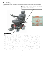
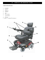
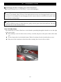
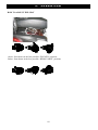
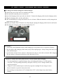
1
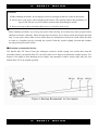
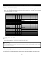
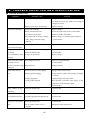
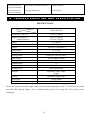
SUNFIRE PLUS GT
SPGT-3C-BL, SPGT-3C-R, SPGT-3C-G
OWNER’S MANUAL
1
TA BLE OF CONTENTS
1.
PREFACE AND INTRODUCTION ……..…………………………………
3
2.
SAFETY NOTICE………..…………………….................……… ……….
Before driving
While driving
Labeling
4
3.
EMI……………………………………………..……………………………….. 10
4.
PARTS INTRODUCTION……………………………………………..………. 11
5.
OPERATION………………………………………………………………….... 12
6.
Control panel
How to operate your power chair
How to set to freewheel mode
BATTERY CHARGING AND CARE……………………………………….... 20
Charging the battery
Battery
Replacing the batteries / charger
7.
INSPECTION AND MAINTENANCE……………………………………..…. 23
Inspection
Regular checking record
Battery, fuse and tire
Storage
8.
TROUBLE SHOOTING AND SPECIFICATION…………….……………
9.
WARRANTY…………………………………………………………………..... 29
2
26
1.
PR E FAC E A ND I N T ROD UC T I O N
Please carefully read this owner’s manual before using the power chair. Improper use of the power chair
could result in, injury.
This owner’s manual includes operating instructions for every aspect of the power chair, including
assembly instructions and how to deal with possible accidents.
The symbols used in this manual are explained below:
Read carefully the notes marked with these symbols:
Warning Improper usage could result in serious injury or death
Attention Improper usage could lead to injury and/or damage to your power chair.
Suggestion
Follow these instructions to keep your power chair in a good operating order.
This manual includes a copy of repair and maintenance record chart and warranty information.
Please keep it in a safe place.
If someone else uses the power chair, please make sure that you provide them with the instruction
manual for his or her consideration.
We reserve the right to make design modifications. As designs change, some illustrations and pictures
in the manual may not correspond to the power chair that you have purchased.
“Caution: Federal law restricts this device to sale by or on the order of a
practitioner licensed by the law of the State in which he/she practices.”
3
2.
SAFETY
N OT I CE
2.1 BEFORE DRIVING
The user should become familiar with the usage and operation of this power chair before driving.
Therefore, please always keep the following safety notices in mind.
For your safety, please follow these rules.
Drive on the pavement, or pedestrian areas only.
Do not drive your power chair after consuming alcohol.
Please be careful when driving your power chair in low light. It has not been designed for use at night.
The power chair has been designed to operate on pavement for speeds up to 4.5mph.
Practice operating your power chair
Before using the power chair, familiarize yourself with the operation of your power chair.
Turn the speed dial to value 1 for your initial use.
Be sure someone accompanies you for safety when operating you power chair for the first time.
Only use higher speed setting when you are confident that you can easily operate and control your
power chair.
The Sunfire Plus GT Chair is only to be used by one person at a time
Do not carry passengers on your power chair. (including children)
Do not use this power chair to carry or haul goods
The maximum weight with occupant is 250 lbs.
2.2 WHILE DRIVING
Carry out daily inspections. Refer to the section titled “DAILY CHECKING”
Do not move your body out of the power chair while moving
Such action may cause you to lose balance and risk injury from falling.
Pay attention that your clothes do not tangle in the wheels.
4
2.
SAFETY
N OT I CE
Do not use your power chair under any of the conditions below.
On roads with heavy traffic or roads that are unpaved, snow-covered, or icy.
Do not drive at night. Do not drive in rain or show.
Do not drive your power chair in an “S” pattern or make erratic turns.
Do not take the power chair onto escalators.
UNDER NO CIRCUMSTANCES SHOULD THE POWER CHAIR BE USED AS A SEAT IN
ANOTHER MODE OF TRANSPORTATION (CARS, BUSES, TRAINS, ETC).
About Mobile Phones and other electrical equipment
Do not use a mobile phone or other wireless communication device while driving.
Always switch off the power chair and remove the ignition key before using a mobile phone.
Do not charge the mobile phone or any other electrical device from the power chair battery.
Automatic Power Shut Down
In order to avoid accidental battery run down, your power chair is equipped with an automatic power
shut down . If the power chair is turned on, it will automatically turn off after remaining undisturbed for
a period of thirty minutes. When this situation occurs, simply switch your power chair off and back on
and it will be ready to use once again.
Ramps, inclines and drops
Do not drive onto ramps that are steeper than the specified gradient. Refer to the section entitled
“CLIMBING ANGLE” in “8. SPECIFICATION”
Always use a low speed setting when ascending or descending a gradient.
Do not drive on roads with large drops or potholes. Refer to the section entitled “MAX. GROUND
CLEARANCE” in “ 8. SPECIFICATION”.
Operate with slow speed when driving on roads with inclines.
Do not make sudden turns when driving on gravel roads or ramps.
Always lean forward when climbing a steep gradient.
Starting and Driving
1. Make sure the seat is installed properly.
2. Fold down the armrests so that you can rest your arms.
3. Turn the power switch to “ON”.
4. Check battery indicator to ensure the chair is properly charged. Recharge the batteries when necessary.
5. Set the speed dial to a safe and comfortable speed.
6. Check the joystick lever to ensure it operates correctly.
7. Make sure the electromagnetic brake works correctly.
5
2.
SAFETY
N OT I CE
8. Engage the 4.5mph switch if you are driving on the pavement.
Warning !
Do not set in the freewheel mode when driving on a gradient.
Always re-engage the anti-freewheel device before use. Fail to do so may result in injury.
To protect your safety, the power will automatically cut off and electromagnetic brake system will
activate while driving down a steep gradient. This will limit the speed to a safe level. Turn the
power on again to re-start your power chair.
Maximum User Weight Limit
Refer to section titled “MAX. LOAD WEIGHT in “8. SPECIFICATION ”. Exceeding the
weight limit may lead to damage to your power chair or cause it to malfunction. This will
endanger your safety. The warranty does not cover this type of damage.
Attention
1. Avoid putting all of your weight on the footrest. This may cause the power chair to tip. possibly
resulting in injury.
2. Do not turn the power switch to OFF while driving as this will lead to an emergency stop and
possible risk of accident and injury.
3. Do not set to the higher speeds while driving indoors.
4. Do not adjust the speed dial while driving; a sudden change in speed may cause danger to you
and others, and may damage your power chair.
5. Do not place magnetic devices near the area of the controller as this could affect the safe
operation of your power chair.
6. Do be careful while driving in heavy traffic or crowded areas.
7. While backing up the power chair, be aware of people or objects behind you.
Stopping
Release the joystick control lever completely. The power chair will come to a stop.
Turn the power switch to “OFF”. Remove the key.
Driving on the pavement
Ensure the speed limit switch is set to the slowest setting when using the power chair. This will limit
the power chair to a maximum speed of 4.5mph.
The speed switch can be set to the fastest setting for use on the road.
6
2.
SAFETY
N OT I CE
Attention:
1.When climbing an incline, do not zigzag or drive at an angle up the face of the of the incline.
2. Always drive your power chair straight up the incline. This greatly reduces the possibility of a
tip or a fall. Always exercise extreme caution when negotiating an incline.
3. Never travel up or down an incline that is wet or covered by snow or ice.
Inclines and uneven terrain
When climbing an incline, try to keep your power chair moving. If you must stop, start up again slowly
and then accelerate cautiously. When driving down an incline, do so slowly and in the forward direction
only. If your power chair starts to move faster than you anticipated or desired it would, allow the chair
to come to a complete stop by releasing the joystick. Push the joystick slightly forward and continue
traveling slowly down the incline.
Maximum recommended incline
The Sunfire Plus GT Power Chair has undergone extensive incline testing. Our results show that the
maximum incline your Sunfire Plus GT can safely climb is five degrees at maximum weight capacity. Five
degrees is the angle of most handicap access ramps. Any attempt to climb a steeper slope may put your
Sunfire Plus GT in an unstable position.
2.
SAFETY
7
N OT I CE
Labeling
Carefully read all the labeling on the power chair before driving it. Do not remove these
labels.
NEVER LIFT POWER CHAIR BY THE
FRONT OR REAR SHROUD
WARNING:
Radio waves may affect power chair control.
Radio wave sources, such as radio stations, amateur radio (HAM) transmitters, two-way radios and
cellular phones can affect powered motorized power chair. Following the warning listed below should
reduce either of the chance of unintended brake release or powered power chair movement, either of
which could result in serious injury.
1. Do not turn ON hand-held personal communication devices, such as citizens band (CB) radios
and cellular phones, while the powered power chair is turned ON.
2. Be aware of near by transmitters, such as radio or TV stations, and try to avoid driving close to
them.
3. If unintended movement or brake release occurs, turn the powered power chair OFF as soon as it
is safe.
4. Be aware that adding accessories or components, or modifying the powered power chair, may
make it more susceptible to interference from radio wave power chair. (Note: There is no easy way
to evaluate their effect on powered power chair.)
5. Report all incidents of unintended movement or brake release to your distributor or dealer and
note whether there is a radio wave source nearby.
8
2.
SAFETY
N OT I CE
This section provides the user with basic information that describes the problems with electromagnetic
interference (EMI), known sources of EMI, protective measure to either lessen the possibility or
exposure or to minimize the degree of exposure, and suggested action should unexpected or erratic
movement occur.
Attention:
It is very important that you read this information regarding the possible effects of
electromagnetic interference on your Sunfire Plus GT power chair.
ELECTROMAGNETIC INTERFERENCE (EMI) FROM RADIO WAVE
SOURCES
The Sunfire Plus GT may be susceptible to electromagnetic interference (EMI), which is interfering
electromagnetic energy (EM) emitted from sources such as radio stations, TV stations, amateur radio
(HAM) transmitters, two-way radios, and cellular phones. The interference (from radio wave sources)
can cause the power chair to release its brakes, move by itself, or move in unintended directions. It can
also permanently damage the powered wheelchair’s control system. The intensity of the interfering
EM energy can be measured in volts per meter (V/m). Each power chair can resist EMI up to a certain
intensity; this is called its “immunity level”. The higher the immunity level, the greater the protection.
At this time, current technology is capable of achieving at least a 20 V/m immunity level, which would
provide useful protection from the more common sources of radiated EMI. This power chair model
has as shipped no further modification to an immunity level of 20 V/m without any accessories.
There are a number of sources of relatively intense electromagnetic fields in the everyday environment.
Some of these sources are obvious and easy to avoid. Others are not apparent and exposure is
unavoidable. However, we believe that by following the warning listed below, your risk to EMI will
be minimized.
The sources of radiated EMI can be broadly classified into three types:
1. Hand-held portable transceivers ( transmitter-receivers with the antenna mounted directly on the
transmitting unit. Examples include: citizens band (CB) radios, “ walkie talkie”, security, fire, and
police transceivers, cellular telephones and other personal communication devices.
Attention:
Some cellular telephones transmit signal while they are ON, even when not being used.
2. Medium-range mobile transceivers, such as those used in police cars, fire trucks, ambulances and
taxis. These usually have the antenna mounted on the outside of the power chair .
3. Long-range transmitters and transceivers, such as commercial broadcast transmitters (radio and TV
broadcast antenna towers) and amateur (HAM) radios.
9
3.
EMI
Attention: Other types of hand-held devices, such as cordless phones, laptop computers, AM/FM
radios, TV sets, CD players, cassette and small appliances such as electric shavers and hair dryers
are not likely to cause EMI problems to your powered power chair .
POWERED POWER CHAIR ELECTROMAGNETIC INTERFERENCE (EMI)
Because EM energy rapidly becomes more intense as one moves closer to the transmitting antenna
(source), the EM fields from hand-held radio wave sources (transceivers) are of special concern. It is
possible to unintentionally bring high levels of EM energy very close to the powered control system
of power chair while using these devices. This can affect powered power chair movement and
braking. Therefore, the warnings listed below are recommended to prevent possible interference with
the control system of the power chair.
WARNINGS
Electromagnetic interference (EMI) from sources such as radio and TV stations, amateur radio (HAM)
transmitters, two-way radios, and cellular phones can affect the power chair. Following the warnings
listed below should reduce the chance of unintended brake release or power chair movement which
could result in serious injury.
1. Do not operate hand-held transceivers-receivers, such as citizens band (CB) radios, or turn ON
personal communication devices such as cellular phones, while the power chair is turned ON.
2. Be aware of nearby transmitters such as radio or TV stations, and try to avoid coming close to them.
3. If unintended movement or brake release occurs, turn the power chair OFF as soon as it is safe;
4. Be aware that adding accessories or components, or modifying the power chair, may make it more
susceptible to EMI (Note: There is no easy way to evaluate their effect on the overall immunity of
the power chair).
5. Report all incidents of unintended movement or brake release to the power chair manufacturer, and
note whether there is a source of EMI nearby.
IMPORTANT INFORMATION
1. 20 Volts per meter (V/m) is a generally achievable and useful immunity level against EMI ( the
higher the level, the greater the protection);
2. This product has an immunity level of 20 V/m without any accessories and connected to it.
10
4.
PA R T S I N T R O D U C T I O N
PARTS DESCRIPTION
1 Controller
2 Armrest
3 Headrest
4 Seatback
5 Seat
6 Drive Wheel
7 Caster Wheel
8 Footrest
9KnobTo Adjust The Armrest
2
.
3.
4.
1
.
9.
5.
8.
6.
7.
11
5.
O P E R AT I O N
JOYSTICK AND CONTROLLER
Your Sunfire Plus GT is operated by a joystick and controller. The Sunfire Plus GT is
currently available with one of two controller options: PG VR 2.
2
1
6
VR2 Series CONTROL FUNCTIONS
1.ON/OFF Button
2. Battery Gauge
4. Maximum Speed / Profile Indicator
5.Speed / Profile Decrease Button
7. Speed / Profile Increase Button
4
3. Joystick
7
5
6.Horn Button
3
HOW TO OPERATE YOUR Mambo
ON/OFF Button
The ON/OFF button applies power to the control system
electronics , which in turn supply power to the power chair’s
motor. Do not use the ON/OFF button to stop the power chair
unless there is an emergency.
Attention:
If you use the ON/OFF button to stop the power chair, it may shorten the life of the
drive components
Battery Gauge
The battery gauge shows you that the power chair is switched on. It also indicates the operating status
of the power chair
Joystick
The primary function of the joystick controls the speed and direction of the power chair. The further you
push the joystick from the center position the faster the power chair will more. When you release the
joystick the brakes are automatically applies.
Maximum Speed / Profile Indicator
This gauge shows the maximum speed setting of the power chair.
There are five speed settings. Step 1 is the lowest speed and step 5 is the highest speed.
12
5.
O P E R AT I O N
Attention:
We recommend that the first few times you operate your Sunfire Plus GT Plus you should turn
the speed and respond adjustment knob to the slowest setting until you become familiar with
you new power chair.
Speed / Profile Decrease Button
This button decreases the maximum speed setting or , if the control system is programmed for drive
profile operation, selects a lower drive profile.
Horn Button
Press button to sound the horn.
Speed / Profile Increase Button
This button increases the maximum speed setting or , if the control system is programmed for drive
profile operation, selects a lower drive profile.
To lock the power chair.
1. While the control system is switched on, depress and hold the on/off button.
2. After 1 second the control system will beep. Release the on/off button.
3. Deflect the joystick forward until the control system beeps.
4. Deflect the joystick in reverse until the control system beeps.
5. Release the joystick, there will be a long beep.
6. The power chair is now locked.
To unlock the power chair.
1. Use the on / off button to switch the control system on. The maximum speed / profile indicator
will be rippling up and down.
2. Deflect the joystick forward until the control system beeps.
3. Deflect the joystick in reverse until the control system beeps.
4. Release the joystick, there will be a long beep.
5. The power chair is now unlocked.
Attention:
This feature is disabled by default; if required, it must be enabled by programming.
13
5.
O P E R AT I O N
JOYSTICK DEPTH ADJUSTMENT
Your power chair is equipped with an adjustable joystick. This function enables you to move the
joystick from the armrest to the desired position.
Suggestion
1. You should recharge the batteries after each time the power chair is used to ensure maximum
2.
3.
4.
5.
6.
range. The batteries should be charged at least once a week even if the power chair is not used.
After charging or replacing a new battery, drive the power chair for 2-3 minutes to make sure
the battery capacity is sufficient.
In wintertime, the battery may respond more slowly and the battery range may be reduced.
When driving on a gradient, the battery indicator light might move up and down. This is a
normal phenomenon and should not cause concern.
Even with proper care and use of the battery, it is natural for the battery’s capacity to reduce
with time. Therefore, if the battery’s range is about 50% of the range when the batteries were
new, it is time for it to be replaced. Please contact your dealer about replacement batteries. If an
old battery is used it can lead to a rapid decline in performance.
The battery range will be reduced when driving frequently on a slope or rough terrain, as this
requires a greater consumption of power.
BRAKING
Electro-magnetic brake: Release the speed control lever completely, the electromagnetic brake will be
activated automatically and the power chair will stop.
Warning
When on a gradient, NEVER switch the power chair to the freewheel mode. The electromagnetic
brakes will not be applied and this may result in injury.
14
5.
O P E R AT I O N
HOW TO ADJUST THE SEAT
To adjust the seatback angle
Pull up the seatback release lever.
Move the seatback down or up to the desired position .
Release the seatback release lever.
To adjust the armrest width
Loosen the knobs
Slide the armrests in or out to the desired width .
Tighten the knobs.
Knob
Seatback Release Lever
Jam Nut
To adjust the armrests angle
Lift-up the armrest.
Looseen the jam nut.
Adjust the socket screw up or down to the desired arm angle position.
Tighten the jam nut.
To determine the same angle for the opposite armrest, count the exposed threads after the jam nut
has been tightened.
If necessary, repeat the steps for the opposite armrest.
15
5.
O P E R AT I O N
To adjust the height of armrests
Loosen knob.
Pull bolt on handle.
Move armrest to required position.
Armrest
knob
To adjust headrest
To raise headrest, lift it to desired position.
To lower headrest, push releaser and lower headrest to desired position.
Releaser
To remove the seat
Turn the power OFF.
Make sure the Sunfire Plus GT is not in freewheel mode.
Push the seat rotate lever while pulling up on the seat to remove.
16
5.
O P E R AT I O N
To change the seat height
Remove seat (See “To remove the Seat”)
Remove the shroud.
Disengage and remove the seat height adjustment pin from the seat post.
Remove the height adjustment pin from each of the three posts.
Raise or lower each post to the desired position.
Reinstall the seat height adjustment pin through the seat post and armrest post.(Bend the end of the
pin lock and position it over the end the pin.)
Reinstall the shroud.
Reinstall the seat.
HOW TO ADJUST THE FOOTREST
To adjust the footrest angle
You can adjust the angle of the footrest with an Allen key (M6).
Turn the setscrew clockwise to raise the front of the footrest.
Turn the setscrew clockwise to lower the front of the footrest.
Hexagon bolt
HOW TO SET TO FREEWHEEL MODE
For your convenience, the Sunfire Plus GT is equipped with a freewheel level. This level allows you to
disengage the drive motors and maneuver the chair manually.
To engage the drive and take power chair out of freewheel
Pull the freewheel lever to ”DRIVE” position(left and right).
Activation of the joystick automatically releases the brake so the powered Sunfire Plus GT can be
driven.
17
5.
O P E R AT I O N
To disengage the drive and place power chair in freewheel
“
”left and right)
Warning
Do not use your Sunfire Plus GT Power Chair while the drive motors are disengaged unless you are in
the presence of an attendant! Do not disengage the drive motors when on an incline as the power chair
may roll down causing injury!
Suggestion
If a level is difficult to move in either direction, gently rock the power chair back and front. The level
should then move to the desired position.
CIRCUIT BREAKERS
The Sunfire Plus GT Power Chair has a circuit breaker protruding through the shroud cover at the right
of the power chair.
In the unlikely event of a short circuit or heavy overload, all power to the power chair will be shut
off.
To reset, depress the circuit breaker button. Wait a few minutes for the circuit breaker to reset.
If the power chair continues to shut down after resetting, have it serviced by a dealer.
18
5.
O P E R AT I O N
HOW TO ADJUST THE SEAT
Above: Seat shown in the four possible “ENGAED” positions
Below: Seat shown in the four possible “REMOVABLE” positions
19
6 . B AT T E R Y C H A R G I N G A N D C A R E
BATTERIES
The Sunfire Plus GT Power Chair uses two long- lasting, 12 volt, deep-cycle batteries. These
batteries are sealed and maintenance free. Since they are sealed, there is no need to check the
electrolyte (fluid) level. Deep-cycle batteries are designed to handle a longer and deeper discharge.
Though they are similar in appearance to automotive batteries, they are not interchangeable.
Automotive batteries are not designed to handle a long, deep discharge and are unsafe for use in
powered power chairs.
These batteries are maintenance free and there is no need to refill with water.
Do not expose the battery to temperatures below 50F or above 122F when charging or storing
the power chair. Exposure of the battery under the above temperature range can cause the battery to
either to freeze or overheat, causing damage and shortening its life.
Warning
Battery posts, terminals and related accessories contain lead and lead compounds. Wash hands after
handling!
Use proper batteries
Your power chair operates on two 12 volt batteries.
They should be U1 size with minimum of 34 amp hour rating . Only deep cycle sealed case
construction batteries should be used in the power chair.
When buying a replacement, insist on a deep cycle sealed case. Do not use any other type.
CHARGING THE BATTERIES
The battery charger is essential in providing long battery life. Located underneath the utility tray,
it is designed to optimize your Sunfire Plus GT performance by charging safely, quickly and
easily. The power chair Amp meter and charger plug are located on the utility tray for easy
viewing. The Amp meter indicates the rate of charge being administered to fully recharge the
batteries. It is also a good indication of whether or not the charger is working. The Amp meter
and the charger are only functional when the charger power cord is plugged into a wall outlet.
20
6 . B AT T E R Y C H A R G I N G A N D C A R E
To charge the batteries using the on-board charger
Position the power chair next to a standard wall outlet
Be certain the controller power is turned off .
Open the charging socket cap on the rear shroud. Connect the charging cable into the charging socket.
Plug the charging cable into the wall outlet.
We recommended you charge the batteries for 8 to 14 hours. When the batteries are fully charged, the
Amp meter to zero area.
When your Sunfire Plus GT batteries are fully charged, unplug the charging cable from the wall outlet.
Disconnect the charging cable from the Sunfire Plus GT.
ON-board Charging
Warning
Keep away from flammable objects while charging as it may lead to fire or explosion of battery.
2. Do not smoke while charging as the battery may release hydrogen gas. Always charge the battery in a
well-ventilated space.
3. Avoid electric shock! Never connect or disconnect the plug or cord with wet hands while charging.
Do not connect or disconnect the plug or cord when they are wet.
6.
Attention - Follow these safety rules below to avoid accidents while charging.
1. Use the manufacturer’s supplied charger only, and recharge the battery to its full capacity
every time. You may damage the battery and power chair if you use a charger which is not
correctly specified.
2. Charge in a well-ventilated space not directly exposed to sunlight. Do not charge in areas
that are humid or exposed to rain, mist or dew.
3. Do not charge in temperatures 14°F or higher than 122°C as the charger may cause battery
damage.
21
6 . B AT T E R Y C H A R G I N G A N D C A R E
Suggestion – How to maximize your battery’s efficiency and service life
1. Fully charge any new battery before its initial use.
2. Be sure to charge the battery after each use. Battery power will be reduced if the battery is used
without being fully charged.
3. If the power chair is not used for an extended period, batteries should be charged at least
weekly .
4. The ambient temperature affects charging time. Charging time will be longer in cold
temperatures.
5. After charging, do not leave the charger socket plugged in.
Cleaning the battery
If the batteries are contaminated by water, battery acid, dust or other substances, they will discharge
quickly. The batteries supplied with the power chair are sealed and as such are maintenance free with no
risk of battery leakage. Please follow the steps below to clean the battery.
Turn the Sunfire Plus GT power switch to OFF.
Remove the seat .
Remove the shroud and unplug the terminal of the taillight and signal lights.
Use a clean cloth to wipe off the soiled area.
Remove the battery.
Wipe with a clean cloth. If the terminal is covered with white powder, wipe it clean using warm water.
Batteries replacement
Remove the seat. (See “To remove the seat”)
Remove the shroud.
Disconnect the negative terminal (black) wires first, then the positive terminal (red) wires by
removing the four nuts and bolts from each of the battery terminals.
Remove the batteries.
Insert new battery.
Connect the positive terminal (red) wires first, then the negative terminal (black) wires by tightening
the nuts and each battery terminal.
Install the shroud and seat.
Warning Be sure the battery wires are connected to the right battery terminal.
Suggestions
1. Make sure the terminals are installed properly and replace the cover.
2. Battery efficiency will vary with outside conditions- driving range will be reduced in cold
weather If the power chair is not used for a long time, charge the battery at least once a week.
3. Replace both batteries together.
22
7. INSPECTION AND MAINTENANCE
INSPECTION
Initial adjustments should be made to suit personal body structure and preference. Be sure to, follow
these checks and maintenance procedures.
NO.
Item
1
General(Mechanical Troubleshooting)
power chair rolls straight(no excessive drag or pull to one
side).
Arms
Secure but easy to release; adjustment levers engage
properly.
Adjustable height arms operate and lock securely.
Pivot point free of wear and looseness.
2
3
4
5
6
7
8
9
initially
Seat
Seat secured to the power chair frame.
Inspect seat release latches
Caster assemblies
Bolts are tight.
Inspect caster assembly for proper tension by spinning
caster assembly; caster assembly should come to a
gradual stop.
Attention: As with any power chair, the wheels and tires
should be checked periodically for cracks
and wear, and replaced if necessary.
Caster assemblies/ wheel
Ensure all fasteners are secure.
Wheels/tires
Inspect for flat fasteners are secure.
Attention: As with any power chair, the wheels and tires
should be checked periodically for cracks
and wear, and replaced if necessary.
Cleaning
Clean upholstery and armrests.
23
monthly periodically
Seat and back upholstery
Inspect for rips or sagging.
Drive wheel
Mounting bolts are secure
No excessive side movement or binding when lifted and
spun when disengaged (free-wheeling)
weekly
7. INSPECTION AND MAINTENANCE
REGULAR CHECKING RECORD
To make sure your power chair is correctly serviced, take it to your dealer for regular maintenance
checks. The initial inspection should be made after the first month’s use, thereafter every six months.
Your dealer may charge a fee for this.
YEAR
Service Dates
Controller
On/off switch
Joystick
Braking
Recharge point
Batteries
Levels
Connections
Discharge test
Wheels and Tires
Wear
Pressure
Bearings
Wheel nuts
Motors
Wiring
Noise
Connections
Brake
Brushes
Chassis/Footrest
Condition
Footrest
1
2
3
4
YEAR
Service Dates
Upholstery
Seat
Back
Armrests
Electrics
Connections
condition
Utility tray
Test run
Forwards
Reverse
Stop
Left turn
Right turn
Slope test
Over obstacles
List Items repaired
1
2
3
4
BATTERY, FUSE AND TIRE
Battery
Refer to the section titled “ BATTERY CHARGING AND CARE ”
Suggestion Ask for help from your certified Drive dealer to inspect or replace the fuse as the steering shroud
must be removed for access
Tires
The condition of the tires depends on how you drive and use your power chair.
Inspecting Tire Tread
Please check the tread depth regularly. Replace the tires when the tread depth is less than 0.5 mm.
24
7. INSPECTION AND MAINTENANCE
Attention
When tread depth is below 0.5mm it can easily lead to power chair slippage, making braking
distances longer. Therefore replace the tyres as early as possible when they are found to have
insufficient tread depth.
Attention
Before doing any maintenance, turn the power switch to OFF and remove the charger cords.
Suggestions
1. Do not splash water onto the power chair as this could cause the electronic system to
malfunction.
2. Do not use caustic material, solvents or aerosols as these may deform or damage the shrouds.
3. Do not use wax.
STORAGE
Make sure the power chair is stored as follows:
With the charger unplugged
With the power switch OFF
Suggestion Always store the power chair in a location where it is out of direct sunlight, rain or dew. If storing
for an extended period, charge the battery to full power and then disconnect the battery terminal.
For details contact a certified Drive dealer.
25
8 . T R O U B L E S H O O T I N G A N D S P E C I F I C AT I O N
TROUBLE SHOOTING
Symptom
Probable cause
Solution
Limited driving distance Batteries not fully charged.
Charge batteries overnight or ensure 10 hours
of charge between uses. Make sure setting on
charger is correct.
Batteries not charging.
Batteries weak won’t hold charge.
Replace batteries
Charger not working
Replace charger.
Battery connections loose.
Check all connections. Secure connections.
No current at wall outlet.
Switch to another wall outlet.
Bad connection on charger, charger
Replace charger or internal repairs required.
cable, plug or internal wiring
Contact dealer.
problem.
Batteries draw excessive Battery failure.
Replace batteries
current when charging.
Charge indicator shows Batteries weak won’t hold charge.
low charge
Electrical malfunction.
Replace battery
Contact dealer
Level immediately after Charger not operating.
Replace charger
charging.
Battery indicator flashes Have charger checked.
Service or replace charger.
the charge level is
Contact dealer
low-too soon after being Weak batteries.
Replace batteries
recharged.
Wheel chair will not
Motor release levers disengaged.
Engage motor release levers.
drive
Battery require charging.
Charge batteries. Make sure setting on charger
is correct.
Charger plugged in.
Unplug charger from wall outlet.
Circuit breaker tripped.
Reset breaker. If breaker trips again, it may
indicate need for internal repairs.
Contact dealer.
Motor “chatter” or runs Electrical malfunction.
Contact dealer
irregularly.
Joystick erratic or does Electrical malfunction.
not respond as resired.
Contact dealer
Controller programmed improperly.
Only one (1) rear wheel Electrical malfunction.
turns.
Contact dealer
Contact dealer
One (1) motor release lever is
engaged.
26
Disengage motor release lever.
Wheelchair does not
Poor battery terminal connection.
Clean terminals.
Electrical malfunction.
Contact dealer
respond to commands.
Power indicator off
even after recharging.
8 . T R O U B L E S H O O T I N G A N D S P E C I F I C AT I O N
SPECIFICTIONS
MODEL
Sunfire Plus GT
ITEM
Dimension (LWH )
382242 inches
Weight, with batteries
Without batteries
81/178.2 Kg/lbs
59.2/130.2 Kg/lbs
Battery
12V 34Ah2
Motor
200W2
Charger
DC24V 3A ON-board
Caster wheels
8“2 Solid
Drive wheels
10“2 Solid
Driving system
Direct drive the rear wheel
Brake system
Electromagnetic brakes
Top speed
7.2 km/hr /4.5mph
Climbing angle
8°
Cruising range
35km/21.8miles
Turning radius
508/20 mm/inches
Armrests
Adjustable Width, Angle,
Height
Footrest
Adjustable Height, Angle
Max weight
136 kg/300lbs
Controller
PG VSI 50A
Please note that the maximum range is based on an ambient temperature of 68 , a 165 lb driver, a brand
new and fully charged battery, and a constant driving speed of 4.5 mph with 70% battery power
discharged.
27
8 . T R O U B L E S H O O T I N G A N D S P E C I F I C AT I O N
Self-Help Guide
If a system trip occurs, you can find out what has happened by counting the
Number of bars on the battery gauge that are flashing.
Overleaf is a list of self-help actions. Try to use this list before you contact
your service agent. Go to the number in the list that matches the number
Of flashing bars and follow the instructions.
If the problem persists after you made the checks described above contact
Your service agent.
1 bar
2 bars
The battery needs charging or there is a bad
Connection to the battery. Check the connections to
The battery. If the connections are good, try charging
The battery.
The left hand motor has a bad connection. Check
the connections to the left hand motor.
3 bars
The left hand motor has a short circuit to a battery
Connection. Contact your service agent.
4 bars
The right hand motor has a bad connection. Check
The connections to the right hand module.
5 bars
The right hand motor has a short circuit to a battery
Connection. Contact your service agent.
6 bars
The wheelchair is being prevented from driving by an
External signal. The exact cause will depend on the
Type of wheelchair you have, one possibility being that the
battery charger is connected.
A joystick fault is indicated. Make sure that the
joystick is in the center position before switching on
The control system.
A control system fault is indicated. Make sure that all
connections are secure.
7 bars
8 bars
9 bars
10 bars
The parking brakes have a bad connection. Check the
Parking brake and motor connections. Make sure the
Control system connections are secure
An excessive voltage has been applied to the control
system. This is usually caused by a poor battery
connection. Check the battery connections.
28
9. WARRANTY
Your Drive brand product is warranted to be free of defects in materials and workmanship as follows:
Chair/Scooter frame: Lifetime
Electronic Controller and drive train components: 1 year
Batteries: 6 months from time of installation
This device was built to exacting standards and carefully inspected prior to shipment. This Lifetime Limited Warranty
is an expression of our confidence in the materials and workmanship of our products and our assurance to the consumer
of years of dependable service.
In the event of a defect covered by this warranty, we will, at our option, repair or replace the device.
This warranty does not cover device failure due to owner misuse or negligence, or normal wear and tear. The warranty
does not extend to wearable components.
If you have a question about your Drive device or this warranty, please contact an authorized Drive dealer.
WARRANTY CONDITIONS:
1.
Any work or replacement part installation must be carried out by an authorized Drive dealer/ service agent.
2.
Should your power chair require attention under this warranty, please contact an authorized Drive dealer.
3.
Any repaired or replaced parts will be covered by this warranty for the balance of the warranty period on the power chair.
4.
The above warranty conditions apply to an new power chair purchased at the full retail price. If you are unsure whether
your power chair is covered, check with an authorized Drive dealer.
5.
Under normal circumstances, no responsibility will be accepted where the power chair has failed as a direct result of:
a. The power chair part not having been maintained in accordance with the manufacturer’s recommendations.
b. Failure to use the manufacturer’s specified parts.
c. The power chair or part having been damaged due to neglect, accident or improper use.
d. The power chair or part having been altered from the manufacturer’s specifications or repairs having been
attempted before the service agent is notified.
The manufacturer reserves the right to alter without notices any weights, measurements or other technical data shown in
this manual. All figures, measurements and capacities shown in this manual are approximate and do not constitute
specifications.
Drive authorized Service Agent
Name
Address
Tel
Postcode
29
Wa r r anty Re gistr ation
Please type or print.
Serial # _______________________________________
Owner Name
Date Purchased
____/____/____
____________________________________________________________
Address
_________________________________________________________________
City
____________________________________
State ________
Zip
________
Additional Required Owner Information
Please indicate your understanding of your scooter by completing the following information.
________
I have read and fully understand
_______
Owner’s Manual, especially sections on operating instructions, safety guidelines,
maintenance and battery instructions.
_______
Scooter Warranty
Battery Instructions – only sealed lead acid or gel cell type batteries should be
used. Batteries must also be sealed, deep cycle, and maintenance free or battery
will hinder vehicle performance and void the warranty.
_______
My dealer has instructed me on how to operate my scooter.
Signature
______________________________Dealer Name
Telephone (____) ________________________Dealer Phone
___________________________
(____)_____________________
Email Address_____________________________________________________________________
Comments:_________________________________________________________________________
______________________________________________________________________________________________________
______________________________________________________________________________________________________
______________________________________________________________________________________________________
______________________________________________________________________________________________________
____________
30
9. WARRANTY
VIN (POWERCHAIR INDIFICATION NUMBER)
To ensure the correct after sales, service and warranty service
support, please write down the power chair identification number
found on the rear right-hand side of the frame.
Model
Sunfire Plus GT
Identification Number
VIN
Motor serial #
Controller #
……………………………………………
……………………………………………
……………………………………
Warranty Application Form
Name
Date of Birth
Year
Month
Day
Address
Model
VIN
Power chair VIN:
Motor Serial No:
Date of Purchase
Year
Month
Controller #
Day
Purchaser Signature
31
99 Seaview Boulevard
Port Washington, NY 11050
516-998-4600
877-224-0946
www.drivemedical.com
32