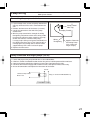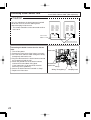
1
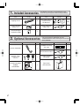
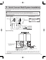
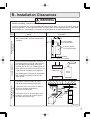
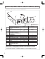
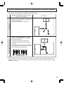
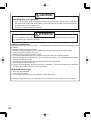
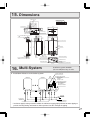
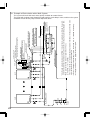
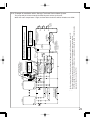
Installation Manual
NORITZ AMERICA
CORPORATION
TANKLESS GAS WATER HEATER
NC380-SV-ASME
(Indoor/Outdoor Installation)
Potential dangers from accidents during installation and use are divided into the following three
categories. Closely observe these warnings, they are critical to your safety.
DANGER
WARNING
CAUTION
DANGER indicates an imminently hazardous situation which,
if not avoided, will result in death or serious injury.
WARNING indicates a potentially hazardous situation which,
if not avoided, could result in death or serious injury.
CAUTION indicates a potentially hazardous situation which,
if not avoided, may result in minor or moderate injury.
WARNING: If the information in this manual is not followed exactly, a fire or explosion may result
causing property damage, personal injury or death.
Disconnect
Power
Prohibited
Ground
Be sure to do
CAUTION
Requests to Installers
• In order to use the water heater safely, read this installation manual carefully, and follow the
installation instructions.
• Failures and damage caused by erroneous work or work not as instructed in this manual are not
covered by the warranty.
• Check that the installation was done properly in accordance with this Installation Manual upon
completion.
• After completing installation, please either place this Installation Manual in a plastic pouch and
attach it to the side of the water heater (or the inside of the pipe cover or recess box if applicable),
or hand it to the customer to retain for future reference. Also, be sure to fill in all of the required
items on the warranty and to hand the warranty to the customer along with the Owner's Guide.
CERTIFIED
Installation must conform with local codes, or in the absence
of local codes, the National Fuel Gas Code, ANSI Z223.1/
NFPA 54- latest edition and/or CSA B149.1, Natural Gas
and Propane Installation Code (NSCNGPIC).
R
Low NOx
Approved by
SCAQMD
SBA8381
Rev. 09/09
Noritz America reserves the right to discontinue, or change
at any time, the designs and/or specifications of its products
without notice.
Accepted For Use
City of New York
Department of Buildings
MEA 19-03-E
*SBA8381*
1. Included Accessories
Part
Shape
The following accessories are included with the unit.
Check for any missing items before starting installation.
Q’ty
Part
Tapping Screw
5
Owner's Guide, Warranty,
Installation Manual
(this document)
1
each
Remote Controller
(See p. 21)
1
Remote Controller
Cord (10ft)
1
Heat Exchanger
Inspection report
1
2. Optional Accessories
Part
System Controller
Shape
Q’ty
Remote Controller
Outdoor
Junction Box
2
Q’ty
The accessories listed below are not
included with the units, but may be necessary
for installation.
Part
Shape
Q’ty
Outdoor Vent Cap
(VC-132)
1
Quick Connect Cord
1
1
Remote Controller
Cord (26ft)
1
1
Pipe Cover
(PC-4S-SUS)
1
1
Isolation Valves
(includes pressure
relief valve)
Shape
3. Quick Connect Multi System Installation
• The Quick Connect Multi System allows the installation of two units together utilizing only the Quick
Connect Cord.
The Quick Connect Cord is 6 ft. long. Install the units 6-17" apart from each other to ensure the
cord will be able to reach between the units. (See Typical Plumbing diagram).
(If the distance between the two units is too great, not only will the cord not be able to reach,
but the water temperature may also become unstable because of the difference in pipe length
between the two units).
* When connecting two units, use only a
single remote controller.
System Diagram
Quick Connect
Cord
Cord
Connector
Cord
Connector
Terminal Block
Remote Controller
Note: Connect the remote
controller to only one
of the units.
Remote Controller Cord
Gas Supply Piping
G
Cold Water Supply
Hot Water
Typical Plumbing
Distance at center: 25-36 in.
Distance on sides
6-17 in.
Union
Union
Quick Connect
Cord
Make this distance as short as possible.
* The hot water temperature will
become unstable as the pipe
length increases.
Pressure
Relief
Valve
Union
Shutoff
Valve
Gas Valve
Shutoff Valve
Shutoff
Valve
Hot Water
Cold Water
Leave enough clearance around the plumbing
to apply insulation. It will be necessary to add
bends to the piping to ensure that this
clearance is available.
Size the piping to allow for the maximum
flow rates of the units.
• Insulate the hot water piping to prevent heat loss. Insulate and apply heating materials to the cold
water supply piping to prevent heat loss and freezing of pipes when exposed to excessively cold
temperatures.
3
4. Before Installation
DANGER
Checkup
• Check the fixing brackets and vent pipe yearly for damage or wear. Replace if necessary.
WARNING
Check the Gas
• Check that the rating plate indicates the
correct type of gas.
• Check that the gas supply line is sized for
380,000 Btuh for this unit.
NC380-SV-ASME
NC380-SV
-ASME
380,000
22,500
376
5
0.6
892
10.5
2.0
4
Check the Power
• The power supply required is 120VAC, at 60Hz.
Using the incorrect voltage may result in fire or electric shock.
Use Extreme Caution if Using With a Solar Pre-Heater
• Using this unit with a solar pre-heater can lead to unpredictable output temperatures and
possibly scalding. If absolutely necessary, use mixing valves to ensure output temperatures do
not get to scalding levels. Do not use a solar pre-heater with the quick-connect multi-system.
CAUTION
Do Not Use Equipment for Purposes Other Than Those Specified
• Do not use for other than increasing the temperature of the water supply, as unexpected accidents
may occur as a result.
Check Water Supply Quality
• If the water supply is in excess of 12 grains per gallon (200 mg/L) of hardness, acidic or otherwise
impure, treat the water with approved methods in order to ensure full warranty coverage.
4
5. Choosing Installation Site
* Locate the appliance in an area where leakage from the unit or connections will not result in damage
to the area adjacent to the appliance or to the lower floors of the structure. When such locations
cannot be avoided, it is recommended that a suitable drain pan, adequately drained, be installed
under the appliance. The pan must not restrict combustion air flow.
DANGER
• Install the exhaust vent so that there are no obstacles around the termination and so that
exhaust can't accumulate. Do not enclose the termination with corrugated metal or other
materials.
WARNING
• Avoid places where fires are common, such as those where gasoline,
benzene and adhesives are handled, or places in which corrosive gases
(ammonia, chlorine, sulfur, ethylene compounds, acids) are present.
Using the incorrect voltage may result in fire or cracking.
Prohibited
• Avoid installation in places where dust or debris will accumulate.
Dust may block the air-supply opening, causing the performance of the
device fan to drop and incomplete combustion to occur as a result.
• Avoid installation in places where special chemical agents
(e.g., hair spray or spray detergent) are used.
Ignition failures and malfunction may occur as a result.
• Carbon Monoxide Poisoning Hazard. Do not install this water heater in a
mobile home, recreation vehicle or on a boat.
CAUTION
• Install the water heater in a location where it is free from obstacles and stagnant air.
• Consult with the customer concerning the location of installation.
• Do not install the water heater near staircases or emergency exits.
• Do not install the water heater where the exhaust will blow on outer walls
or material not resistant to heat. Also consider the surrounding trees and
animals.
The heat and moisture from the water heater may cause discoloration of
walls and resinous materials, or corrosion of aluminum materials.
• Do not locate the vent termination directed towards a window or any other
structure which has glass or wired glass facing the termination.
5
CAUTION
• Avoid installation above gas ranges or stoves.
• Avoid installation between the kitchen fan and stove. If oily
fumes or a large amount of steam are present in the installation
location, take measures to prevent the fumes and steam from
entering in the equipment.
Prohibited
• Install in a location where the exhaust gas flow will not be
affected by fans or range hoods.
• Take care that noise and exhaust gas will not affect neighbors.
Avoid installation on common walls as the unit will make some
operational noises while it is running.
Be sure to do
• Make sure that the location allows installation of the exhaust
vent as specified.
• For outdoor installation, use the outdoor vent cap.
If it is necessary to vent above the roof line in an outdoor installation, use high temperature sealant around the flue collar for
rain protection.
Prohibited
• Avoid installation where the unit will be exposed to excessive
winds.
• Before installing, make sure that the vent termination (or the vent
cap in an outdoor installation) will have the proper clearances
according to the National Fuel Gas Code (ANSI Z223.1).
State of California: The water heater must be braced, anchored or strapped to avoid moving during an
earthquake. Contact local utilities for code requirements in your area or call: 1-866-766-7489 and request
instructions.
The Commonwealth of Massachusetts: The water heater can be used for hot water only and not in a
combination of domestic and space heating.
For Venting Manufacturers Requirements, see websites or phone numbers listed below:
Noritz N-Vent
6
www.noritz.com
6. Installation Clearances
WARNING
Before installing, check for the following:
Install in accordance with relevant building and mechanical codes, as well as any local, state or
national regulations, or in the absence of local and state codes, to the National Fuel Gas Code ANSI
Z223.1/NFPA 54 – latest edition. In Canada, see NSCNGPIC for detailed requirements.
Required Clearances
From Heater
Item
Check
Illustration
• Maintain the following clearance from
both combustible and non-combustible
materials.
12" or more(Indoor)
36" or more(Outdoor)
4" or more(Indoor)
24" or more(Outdoor)
6" or more(Indoor)
Cooking Equipment
24" or more(Outdoor)
• If the unit will be installed in the vicinity of a
permanent kitchen range or stove that has
the possibility of generating steam that
contains fats or oils, use a dividing plate or
other measure to ensure that the unit is not
exposed to air containing such impurities.
* The dividing plate should be of noncombustible material of a width greater than the
water heater.
Exhaust hood
Dividing plate
Water
heater
Range
• If possible, leave 8" or more on either
side of the unit to facilitate inspection.
Securing of space for
repair/inspection
3" or more
• If possible, leave 24" or more in front of
the unit to facilitate maintenance
and service if necessary.
• If possible, leave 3" or more above and
below the vent pipe to facilitate inspection and repair if necessary
3" or more
8" or
more
8" or
more
24" or
more
(unit: inch)
7
Clearance Requirements from Vent Terminations to Building Openings
* All clearance requirements are in accordance with ANSI Z21.10.3 and the National Fuel Gas Code,
ANSI Z223.1 and in Canada, in accordance with NSCNGPIC.
Vent Terminal
Air Supply Inlet
Clearance
A=
B=
C=
D=
E=
F=
G=
H=
I=
J=
K=
L=
M=
Above grade, veranda, porch, deck,
or balcony
Area Where Terminal
is Not Permitted
Indoor Installation
(See p.9)
Outdoor Installation
(See p.9)
12" (12")
12" (12")
4' below or to the side of
Window or door that may be opened opening, or 1' above opening
12" (36")
(36")
Permanently closed window
*
*
Vertical clearance to ventilated soffit
located above the terminal within a
*
*
horizontal distance of 2 feet from the
center of the terminal
Unventilated soffit
*
*
Outside corner
*
*
Inside corner
*
*
Each side of center line extended
3' within a height 15' above 3' within a height 15' above
above meter/regulator assembly
meter/regulator assembly
meter/regulator assembly
Service regulator vent outlet
3'
3'
4' below or to the side of
Nonmechanical air supply inlet or
12" (36")
combustion air inlet to any other
opening, or 1' above opening
appliance
(36")
Mechanical air supply inlet
3' above if within 10' (6')
3' above if within 10' (6')
Above paved sidewalk or paved
(7' ***)
(7' ***)
driveway located on public property
Under veranda, porch, deck, or
* (12"- Canada Only****)
* (12"- Canada Only****)
balcony
()= indicates clearances required in Canada
*Maintain clearances in accordance with local installation codes and the requirements of the gas supplier
***A vent shall not terminate directly above a sidewalk or paved driveway that is located between two
single family dwellings and serves both dwellings.
****Permitted only if veranda,porch,deck,or balcony is fully open on a minimum of two sides beneath the floor.
8
Clearance Requirements from Vent Terminations to Building Openings
* All clearance requirements are in accordance with ANSI Z21.10.3 and the National Fuel Gas Code,
ANSI Z223.1 and in Canada, in accordance with NSCNGPIC.
Vent Clearances When Heater is Installed Outdoors With a Vent Cap
Vent Clearances When Heater is Installed Indoors
Maintain the following clearances to any
opening in any building:
Illustration
• 4' below, 4' horizontally from, or 1' above
any door, operable window, or gravity air
inlet into any building.
3' above any forced air inlet within 10'.
4'
4'
1'
3'
• 1' below, 1' horizontally from, or 1' above
any door, operable window, or gravity air
inlet into any building.
3' above any forced air inlet within 10'.
• For outdoor installation, use the outdoor
vent cap.
If it is necessary to vent above the roof line
in an outdoor installation, also use the base
of the vent cap for rain protection.
1'
1'
1'
3'
(Noritz vent cap)
* For Installations in Canada, clearances are as follows: To windows, doors, & gravity air inlets: 36".
To forced air inlets: 6'. These clearance requirements hold true for all of the above situations: Indoor,
Outdoor w/vent cap.
9
7. Installation
Securing to the wall
Be sure to do
Item
• The weight of the device will be applied to the wall. If the strength of the wall is not sufficient, reinforcement must be done to prevent the transfer of vibration.
• Do not drop or apply unnecessary force to the device when installing. Internal parts may
be damaged and may become highly dangerous.
• Install the unit on a vertical wall and ensure that it is level.
Check
Locating Screw Holes
CAUTION
• When installing with bare hands, take caution to
not inflict injury.
• Be careful not to hit electrical wiring, gas, or water
piping while drilling holes.
Mounting
Mounting Bracket
(upper)
2. Insert and tighten the screw and hang the unit by
the upper wall mounting bracket.
4. Drill holes for the remaining four screws.
Structure
Location of Screw Hole
1. Drill a single screw hole, making sure to hit a stud.
3. Determine the positions for the remaining four screws
(two for the top bracket and two for the bottom), and
remove the unit.
10
Illustration
5. Hang the unit again by the first screw, and then
insert and tighten the remaining four screws.
6. Take waterproofing measures so that water does
not enter the building from screws mounting the
device.
• Make sure the unit is installed securely so that it will
not fall or move due to vibrations or earthquakes.
Locating Screw Holes
Tapping Screw
8. Vent Pipe Installation (Indoor Installation Only)
WARNING
Be sure to do
CARBON MONOXIDE POISONING
Follow all vent system requirements in accordance with relevant local or state regulation,
or, in the absence of local or state code, in the U.S. to the National Fuel Gas Code ANSI
Z233.1/NFPA 54 – latest edition, and in Canada, in accordance with NSCNGPI.
Vent Piping
• Noritz N-Vent is suggested for the vent system.
If N-Vent is not used, a UL listed category III vent
system must be used.
• Follow the vent pipe manufacturer's installation
instructions.
Pipe diameter
5"
No. of Elbows Max. Straight Vent Length*
3
15'
2
30'
1
45'
* Not including the termination.
• Make the vertical section of the exhaust vent
as short as possible.
• Maintain the same vent pipe diameter from the
heater flue to the vent termination.
Clearances
Manufacturer and
Product
Noritz N-Vent
Enclosed Unenclosed
Hor. Vert. Hor. Vert.
10" (sides)
15"(top)
6"
3"
3"
6"(bottom)
Clearances vary by manufacturer, refer to the UL
approved clearances when using materials other
than N-Vent.
• The first vertical run from the top of the heater
should be no longer than 3'.
• Make sure vent pipe is gas tight and will not
leak. Use silicon sealant wherever necessary.
• Do not common vent or connect more than
one appliance to this venting system.
• The total vent length including horizontal &
vertical vent runs should be no less than 3'.
• Do not store hazardous or flammable substances near the vent termination and check
that the termination is not blocked in any way.
• Steam or condensed water may come out
from the vent termination. Select the location
for the termination so as to prevent injury or
property damage.
• If snow is expected to accumulate, take care
the end of the pipe is not covered with snow or
hit by falling lumps of snow.
• Consult the vent pipe manufacturer's installation instructions for chimney connections.
Appliance Adapters
When using a vent system other than N-Vent,
an appliance adapter will be required to properly
connect the vent to this appliance. Consult the
manufacturer's instructions for the proper appliance adapter.
11
Horizontal Vent Termination
Elbow
Hanger
Straps
Wall
Slope vent Thimble
Downwards
Termination
**1' Min. - 3' Max.
Appliance
Adapter*
* Adapter not required when
using Noritz N-Vent.
**1' minimum recommended,
but not required. Avoid installing
elbow directly on flue.
Vertical Vent Termination
Storm
Collar
Rain
Cap
Roof
Flashing
Roof
Jack
Firestop/
Support
Elbow
**1' Min. - 3' Max.
Hanger
Strap
Firestop
Condensation
Drain (Install
According to
Local Codes)
Appliance
Adapter*
* Adapter not required when
using Noritz N-Vent.
**1' minimum recommended,
but not required. Avoid installing
elbow directly on flue.
12
• Terminate at least 12" above grade or
above snow line.
• Terminate at least 7' above a public walkway, 6' from the combustion air intake of
any appliance, and 3' from any other
building opening, gas utility meter, service regulator etc.
• Terminate at least 3' above any forced air
inlet within 10', 4' below, 4' horizontally
from or 1' above any door, window, or
gravity air inlet into any building per National
Fuel Gas Code ANSI Z223.1/NFPA 54.
• Slope the horizontal vent 1/4" downwards
for every 12" toward the termination.
• Use a condensation drain if necessary.
• In the Commonwealth of Massachusetts
a carbon monoxide detector is required
for all side wall horizontally vented gas
fuel equipment. Please refer to Technical
Bulletin TB 010606 for full installation instructions.
• Terminate at least 6' from the combustion air
intake of any appliance, and 3' from any
other building opening, gas utility meter, service
regulator etc.
• Enclose exterior vent systems below the roof
line to limit condensation and protect against
mechanical failure.
• When the vent penetrates a floor or ceiling and
is not running in a fire rated shaft, a firestop and
support is required.
• When the vent termination is located not less
than 8' from a vertical wall or similar obstruction, terminate above the roof at least 2', but not
more than 6', in accordance with the National
Fuel Gas Code ANSI Z223.1/NFPA 54.
• Provide vertical support every 12' or as required
by the vent pipe manufacturer's instructions.
• Slope the horizontal vent 1/4" for every 12" towards the drain tee.
• A short horizontal section is recommended to
prevent debris from falling into the water heater.
• Install a condensation drain in the horizontal
section of the venting. For installations in tight
spaces where there is not enough room to install two elbows and a horizontal drain tee, a
vertical drain tee may be substituted.
Combustion Air
Supply combustion air to the units as per the National Fuel Gas Code, ANSI Z223.1 and
in Canada, in accordance with NSCNGPIC.
• Provide two permanent openings to allow
circulation of combustion air.
• Make each opening 380 square inches if they
provide indoor air, and 100 square inches for
outdoor air.
• If the unit is installed in a mechanical closet,
provide a 24" clearance in front of the unit to
the door.
• If combustion air will be provided through a
duct, size the duct to provide 100 cubic feet of
fresh air per minute.
14"
28"
28"
14"
Openings supplying indoor air
13
9. Gas Piping
Follow the instructions from the gas supplier.
The appliance and its individual shutoff valve must be disconnected from the gas supply piping system
during any pressure testing of that system at test pressures in excess of 1⁄2 psig (3.5 kPa).
The Appliance must be isolated from the gas supply piping system by closing its individual manual shutoff
valve during any pressure testing of the gas supply piping system at test pressures equal to or less than 1⁄2
psig (3.5 kPa).
The appliance and its gas connections must be leak tested before placing the appliance in operation.
The inlet gas pressure must be within the range specified. This is for the purposes of input adjustment.
In order to choose the proper size for the gas line, consult local codes or the National Fuel Gas Code ANSI
Z223.1.
Gas Pressure
Size the gas line according to total btuh demand
of the building and length from the meter or
regulator so that the following supply pressures
are available even at maximum demand:
Natural Gas Supply Pressure
Min. 5" WC
Max. 10.5" WC
LP Gas Supply Pressure
Min. 10.5" WC
Max. 14" WC
Gas Meter
Select a gas meter capable of supplying the entire
btuh demand of all gas appliances in the building.
Gas Connection
• Do not use piping with a diameter smaller than
the inlet diameter of the water heater.
• Gas flex lines are not recommended unless they
are rated for 380,000 btuh.
• Install a gas shutoff valve on the supply line.
• Use only approved gas piping materials.
Measuring Gas Pressure
In order to check the gas supply pressure to the unit, a
tap is provided on the gas inlet. Remove the hex head
philips screw from the tap, and connect a manometer
using a silicon tube.
In order to check the gas manifold pressure, a pair of
taps are provided on the gas valve inside the unit.
The pressure can be checked either by removing the hex
head philips screw and connecting a manometer with a
silicon tube, or by removing the 1/8" NPT screw with an
allen wrench and connecting the appropriate pressure
gauge.
Sample Gas Line
Noritz Tankless Gas Water Heater
(380,000 Btuh)
Barbecue
(50,000 Btuh)
Outlet E
Outlet A
Clothes Dryer
(35,000 Btuh)
10'
10'
Outlet C
Section 4
5'
Section 3 Section 2
5'
5'
5'
Section 1
10'
5'
Outlet D
10'
Natural Gas
Meter
14
Gas Fireplace
(25,000 Btuh)
5'
Outlet B
Gas Range Stove
(65,000 Btuh)
**See next page for the pipe capacity charts.
Instructions
1. Size each outlet branch starting from the furthest
using the Btuh required and the length from the
meter.
2. Size each section of the main line using the
length to the furthest outlet and the Btuh
required by everything after that section.
Sample Calculation
Outlet A: 45' (Use 50'), 50,000 Btuh requires 1/2"
Outlet B: 40', 65,000 Btuh requires 1/2"
Section 1: 45' (Use 50'), 115,000 Btuh requires 3/4"
Outlet C: 30', 35,000 Btuh requires 1/2"
Section 2: 45' (Use 50'), 150,000 Btuh requires 3/4"
Outlet D: 25' (Use 30'), 25,000 Btuh requires 1/2"
Section 3: 45' (Use 50'), 175,000 Btuh requires 1"
Outlet E: 25' (Use 30'), 380,000 Btuh requires 1-1/4"
Section 4: 45' (Use 50'), 555,000 Btuh requires 1-1/4"
Gas Line Sizing for a Noritz Tankless Gas Water Heater
Adapted from UPC 1997
Maximum Natur
Natural Gas Delivery Capacity in Cubic Feet per Hour (0.60 Specific Gravity, 0.5" WC Pressure Drop)
Pipe
Size
1/2"
3/4"
1"
1 1/4"
1 1/2"
2"
2 1/2"
3"
3 1/2"
4"
Length in Feet
10'
20'
30'
40'
50'
60'
70'
80'
90'
100'
125'
174
56
53
50
44
61
66
73
82
96
119
118
111
104
93
127
138
152
171
200
249
363
222
208
197
174
239
259
286
323
377
470
684
358
404
428
456
490
532
588
663
775
965
1404
536
605
641
734
798
880
993
1445
2103
683
1161
1033
1165
1234
1315
1413
1536
1696
1913
2784
4050
2235
1646
2449
2703
3049
4437
1857
1966
2096
2253
3563
6455
2910
3284
3476
3705
3983
4329
4778
5391
6299
11,412 7843
4261
4808
5090
5425
5831
6338
6995
7893
16,709 11,484 9222
5936
6698
7091
7557
8123
8830
9745
23,277 15,998 12,847 10,995
Contact the Gas Supplier for Btu/Cubic Ft. of the Supplied Gas. 1000 BTU/Cubic Ft. is a Typical Value
Maximum Liquified Petroleum
P
(Undiluted) Delivery Capacity in Thousands of Btuh (0.5" WC Pressure Drop)
Pipe
Size
1/2"
3/4"
1"
1 1/4"
1 1/2"
2"
10'
275
567
1071
2205
3307
6221
20'
189
393
732
1496
2299
4331
30'
152
315
590
1212
1858
3465
40'
129
267
504
1039
1559
2992
50'
114
237
448
913
1417
2646
Length in Feet
60'
70'
80'
89
103
96
217
196
185
409
378
346
834
771
724
1275 1181 1086
2394 2205 2047
90'
83
173
322
677
1023
1921
100'
78
162
307
630
976
1811
125'
69
146
275
567
866
1606
150'
63
132
252
511
787
1496
200'
55
112
213
440
675
1260
** For reference only. Please consult gas pipe manufacturer for actual pipe capacities.
Maximum Capacity of Flex TracPipe in Cubic Feet per Hour of Natural Gas (0.60 Specific Gravity, 0.5" WC Pressure Drop)
R
Pipe
Size
3/4"
1"
1 1/4"
1 1/2"
2"
10'
206
383
614
1261
2934
20'
147
269
418
888
2078
30'
121
218
334
723
1698
40'
105
188
284
625
1472
50'
94
168
251
559
1317
Length in Feet
60'
70'
86
80
153
141
227
209
471
509
1203
1114
80'
75
132
194
440
1042
90'
71
125
181
415
983
100'
67
118
171
393
933
150'
55
94
137
320
762
200'
48
82
116
277
661
Maximum Capacity of Flex TracPipe in Thousands of Btuh Liquified Petroleum ( 0.5" WC Pressure Drop)
R
Pipe
Size
3/4"
1"
1 1/4"
1 1/2"
2"
10'
325
605
971
1993
4638
20'
232
425
661
1404
3285
30'
191
344
528
1143
2684
40'
166
297
449
988
2327
50'
149
265
397
884
2082
Length in Feet
60'
70'
126
136
222
241
330
359
745
805
1902
1761
80'
118
208
307
696
1647
90'
112
197
286
656
1554
100'
106
186
270
621
1475
150'
87
143
217
506
1205
200'
76
129
183
438
1045
** For reference only. Please consult gas pipe manufacturer for actual pipe capacities.
TracPipe® is a registered trademark of Omega Flex.
Maximum Capacity for Gas Flex Connectors in Cubic Feet per Hour of Natural Gas (0.60 Specific Gravity, 0.5" WC Pressure Drop)
Pipe
Size
1/2"
3/4"
1"
1 1/4"
12"
180
24"
150
290
581
1470
36"
125
255
512
1200
Length in Inches
48"
106
215
442
1130
60"
93
197
397
960
72"
86
173
347
930
Maximum Capacity for Gas Flex Connectors in Thousands of Btuh Liquified Petroleum ( 0.5" WC Pressure Drop)
Pipe
Size
1/2"
3/4"
1"
1 1/4"
12"
288
24"
240
465
930
2352
36"
200
409
825
1920
Length in Inches
48"
169
344
708
1808
60"
149
315
638
1536
72"
137
278
556
1488
** For reference only. Please consult gas pipe manufacturer for actual pipe capacities.
15
10. Water Piping
Installation and service must be performed by a qualified plumber. In the
Commonwealth of Massachusetts, this product must be installed by a licensed
plumber or gas fitter in accordance with the Massachusetts Plumbing and Fuel
Gas Code 248 CMR Sections 2.00 and 5.00. Observe all applicable codes.
This appliance is suitable for potable water and space heating applications. Do not use this appliance if any part has
been underwater. Immediately call a qualified service technician to inspect the appliance and replace any part of the
control system and gas control which has been under water.
If the water heater is installed in a closed water supply system, such as one having a backflow preventer in the cold
water supply line, means shall be provided to control thermal expansion. Contact the water supplier or a local plumbing inspector on how to control this situation.
A pressure relief valve must be installed near the hot water outlet that is rated in accordance with and complying with
either The Standard for Relief Valves and Automatic Shutoff Devices for Hot Water Supply Systems, ANSI Z21.22, or
The ANSI/ASME Boiler and Pressure Vessel Code, Section IV ( Heating Boilers ). This pressure relief valve must
be capable of an hourly Btu rated temperature steam discharge of 380,000 Btuh. Multiple valves may be used. The
pressure relief capacity must not exceed 150 psig. No valve shall be placed between the relief valve and the water
heater. The relief valve must be installed such that the discharge will be conducted to a suitable place for disposal
when relief occurs. No reducing coupling or other restriction may be installed in the discharge line. The discharge line
must be installed to allow complete drainage of both the valve and the line. If this unit is installed with a separate
storage vessel, the separate vessel must have its own temperature and pressure relief valve. This valve must also
comply with The Standard for Relief Valves and Automatic Gas Shutoff Devices for Hot Water Supply Systems, ANSI
Z21.22. (in the U.S. only). A temperature relief valve is not required, but if one is used, do not install the valve with the
probe directly in the flow of water. This may cause unwarranted discharge of the valve.
Piping and components connected to the water heater shall be suitable for use with potable water.
Toxic chemicals, such as those used for boiler treatment, shall not be introduced into the potable water.
A water heater used to supply potable water may not be connected to any heating system or components previously
used with a nonpotable water heating appliance.
When water is required in one part of the system at a higher temperature than in the rest of the system, means such
as a mixing valve shall be installed to temper the water to reduce the scald hazard.
• Flush water through the pipe to clean out metal powder, sand and dirt before connecting it.
• Perform the following insulation measures for prevention of freezing.
• Take appropriate heat insulation measures (e.g., wrapping with heat
insulation materials, using electric heaters) according to the climate of Completely insulate
Do not cover the water
the water inlet and
drain plug with insulation
the region to prevent the pipe from freezing.
outlet fittings.
so that water in the pipe
• Make sure that there are no water leaks from the cold and hot water
can be drained.
supply pipes, then insulate the pipes completely.
• Be sure to also completely insulate the water supply valve and the
Insulate the water
cold and hot water connections on the water heater (refer to the figure
supply valve completely.
on the right).
• Do not cover the water drain plug with insulation so that water in the
pipe can be drained. (Refer to the figure in the right.)
• Use a union coupling or flexible pipe for connecting the pipes to reduce the force applied to the piping.
• Do not use piping with a diameter smaller than the coupling.
• When feed water pressure is too high, insert a depressurizing valve, or take water hammer prevention measure.
• Avoid using joints as much as possible to keep the piping simple.
• Avoid piping in which an air holdup can occur.
• If installing the unit on a roof:
• About lower-level hot water supply
If the unit is installed on a roof to supply water to the levels below, make sure that the water pressure supplied to
the unit does not drop below 29 psi. It may be necessary to install a pump system to ensure that the water pressure
is maintained at this level.
Check the pressure before putting the unit into operation.
Failure to supply the proper pressure to the unit may result in noisy operation, shorter lifetime of the unit, and may
cause the unit to shut down frequently.
16
Supply water piping
• Do not use PVC, iron, or any piping which has been
treated with chromates, boiler seal or other chemicals.
• Mount a check valve and a shut off valve (near the inlet).
• In order for the client to use the water heater
comfortably, 98.1 to 491 kPa (14 to 70 PSI) of
pressure is needed from the water supply.
Be sure to check the water pressure. If the water
pressure is low, the water heater cannot perform
to its full capability, and may become a source of
trouble for the client.
Hot water piping
• Do not use lead, PVC, iron or any piping which
has been treated with chromates, boiler seal or
other chemicals.
• The longer the piping, the greater the heat loss.
Try to make the piping as short as possible.
• Use mixing valves with low water resistance. Use
shower heads with low pressure loss.
• If necessary, use a pump or other means to ensure that the supply water pressure to the inlet of
the heater does not fall below 29 PSI when the
maximum amount of water is being demanded.
Drain piping
Also install a pressure meter on the inlet. If this is
• Expansion water may drop from the pressure
not done, local boiling will occur inside the water
prevention device and wet the floor. If necesheater causing abnormal sounds and decreasing
sary, provide drain piping or use a drain hose to
the durability of the heat exchanger.
remove the water.
17
Water Treatment
If this water heater will be installed in an application where the supply water is hard, the water must be
treated with either a water softener, which removes the hardness, or by using sequestering agents, such
as the Noritz Scale Shield, that reduce the amount of scale deposits. Refer to the below tables for suggested treatment and maintenance measures to be taken based on the water hardness level. Damage to
the water heater as a result of water in excess of 12 gpg (200 mg/L) of hardness is not covered by the
Noritz America Limited Warranty.
Note: When installing a water softener, consult with the manufacturer for proper sizing and installation
guidelines; the below diagram is for reference only. For more information about Scale Shield, contact
Noritz America at 866-766-7489.
Residential Use Treatment Guidelines
Type of Water
Hardness
Level
Treatment
Flush
Device Frequency*
0-1 gpg
None
(0-17 mg/L)
1-3 gpg
None
Slightly Hard
(17-51 mg/L)
3-7 gpg
Moderately
ScaleShield
(51-120 mg/L)
Hard
7-10 gpg
ScaleShield
Hard
(120-171 mg/L)
10-14 gpg
Water
Very Hard
Softener
(171-239 mg/L)
Water
> 14 gpg
Extremely
Softener
(> 239 mg/L)
Hard
Soft
None
None
Once a Year
Once a Year
Softener
Required
Softener
Required
* Install Noritz Isolation Valves to allow for flushing.
Commercial Use Treatment Guidelines
Type of Water
Hardness
Level
Treatment
Flush
Device Frequency*
0-1 gpg
(0-17 mg/L)
1-3 gpg
Slightly Hard (17-51 mg/L)
Soft
None
None
None
None
Water
3-7 gpg
Moderately
Once a Year **
Softener
(51-120 mg/L) Suggested
Hard
Hard
Very Hard
Extremely
Hard
7-10 gpg
(120-171 mg/L)
Water
Softener
Suggested
Twice a Year**
10-14 gpg
(171-239 mg/L)
> 14 gpg
(> 239 mg/L)
Water
Softener
Softener
Required
Water
Softener
Softener
Required
*Install Noritz Isolation Valves to allow for flushing.
**Flushing is required if a water softener is not installed.
Water Treatment System
Shutoff Valve
City Water Supply
Cold to Water
Heater
Optional Sediment
Filter
Pressure
Relief
Valve
Shutoff Valve
Water Treatment Device
Hot Water to Fixtures
Drain
18
11. Plumbing Applications
Recirculation System
NORITZ
Tankless Gas
Water Heater
Notes:
1. Size the pump to provide a maximum of 2 GPM
through the system at 10 ft of head plus piping
losses.
Adjust the flow using a globe valve and verify the
flow rate with the maintenance monitors.
2. Pump Control Signal is the preferred method
to control the recirculation pump.
For pumps larger than 85W, a relay connection must
be used. If the Pump Control Signal is not used,
an Aquastat may be used to control the pump.
3. Use an Aquastat if the water heater is not controlling the pump.
Set the Aquastat to 10°F below the set output
temperature.
4. Noritz recommends the use of an Isolation Kit
with the installation.
These kits include an integrated shut-off and service valve with unions and a pressure relief valve.
Hot Water Return
Cold Water Supply
Fixtures
Expansion Tank
(Install according
to local code)
Isolation
Kit(*4)
Gas Supply
Globe
Valve
Aquastat(*3)
Pump Control Signal(*2)
Relay for Pump
(if larger than 85 Watts)
105
Pump
Pump(*1)
R
Optional 8-10 Gallon
Storage Tank
(To alleviate cold water sandwich)
120VAC
B S
Hot Water
W
Neutral
Ground
Live
Aquastat Wiring
Use Honeywell Aquastat
(Model L6006A or L6006C)
Combination Potable Water and Space Heating System
Notes:
1. Noritz recommends the use of an Isolation Kit with
the installation.
These kits include an integrated shut-off and service valve with unions and a pressure relief valve.
2. Size the pump to provide a maximum of 3 GPM
with a head pressure equal to the loss through the
water heater and Air Handler.
3. Check valve required if it is not included with the
pump.
4. Set the flow switch to deactivate the Air Handler
when the domestic hot water flow reaches 3 GPM.
Adjust as necessary to prevent cycling.
Air Handler
NORITZ
Tankless Gas
Water Heater
5. If the system requires water for space heating at
a higher temperature than for other uses, means
such as a mixing valve shall be provided to temper
the water for the other uses to help prevent scald
-ing.
6. Expansion tank required if a backflow preventer is
installed.
Pump(*2)
Isolation
Kit(*1)
Check
Valve(*3)
Gas Supply
Flow Switch(*4)
Backflow Preventer
(optional)
Cold Water
Supply
Optional
Expansion Tank(*6)
Mixing Valve(*5)
Hot Water
Fixtures
19
12. Electrical Wiring
Consult a qualified electrician
for the electrical work.
Do not connect electrical power to the unit until all electrical wiring has been completed.
Disconnect Power
This appliance must be electrically grounded in accordance with local codes, or in the absence of local codes,
with the National Electrical Code, ANSI/NFPA 70. In Canada, the latest CSA C22.1 Electrical Code.
Caution: Label all wires prior to disconnection when servicing controls. Wiring errors can cause improper
and dangerous operation.
Verify proper operation after servicing.
Field wiring to be performed at time of appliance installation.
WARNING
Electrical Shock Hazard
Do not turn power on until electrical wiring is finished. Disconnect power before servicing.
Failure to do so may result in death or serious injury from electrical shock.
• The electrical supply required by the water heater is
120VAC at 60 Hz.
The power consumption may be up to 355W or higher if
using optional accessories.
Use an appropriate circuit.
• Do not disconnect the power supply when not in use. When
the power is off, the freeze prevention in the water heater
will not activate, resulting in possible freezing damage.
• Do not let the power cord contact the
gas piping.
Ground
• To prevent electrical shock, provide a ground
with resistance less than 100 . An electrician
should do this work.
• A grounding screw is provided on the back in
the junction box.
Tie the redundant power cord outside the water heater. Putting the
redundant length of cord inside the
water heater may cause electrical
interference and faulty operation.
Junction Box
Do not connect the ground to the city water
or gas piping. Do not tie the ground to a telephone line.
Breaker Installation
• Mount a device which shuts off the electrical
path automatically (leakage breaker) when
electrical leakage is detected.
Ground
Power Cord
1. Unscrew the junction box and slide it out of the unit.
2. Push the power cord through the bottom of the unit.
3. Connect the live and neutral wires to the black and
white wire in the junction box.
4. Screw the ground wire to the ground screw on the
back in the junction box and replace the junction box.
CAUTION
Electrostatic discharge can affect electronic components. Take precautions to prevent electrostatic discharges from
personnel or hand tools during the water heater installation and servicing to protect product’s electronic control.
20
Remote Controller
• Applicable Model
Noritz Tankless Gas Water Heater
Remote controller
RC-7649M
Install the remote controller according to the instructions in the Installation Guide (p. 31).
• The Noritz Tankless Gas Water Heater can be programmed so that it will default to one of four temperatures if the remote controller is removed (180, 140, 130, 120°F). To change the default temperature, the
remote controller must be initially installed, and removed after programming.
* Changing the default temperature setting:
1. Within the first ten minutes of connecting electrical power to the unit, but before pressing the
Power On/Off button, hit the up [ ] or down [ ] button on the remote controller. This will put
the unit into maintenance writer mode. If pressing either of these buttons does not put the unit
into maintenance writer mode, unplug the unit for sixty seconds and try again.
2. The maintenance monitor item number will flash on the display. (the initial item number will be “99”).
3. The up [ ] and down [ ] buttons can be used to change the maintenance writer item number.
4. Choose a temperature from the chart below and set the 14 and 15 maintenance writers according to
the chart. Pressing the Flow Meter Alarm Set button for 0.5 seconds will switch the indicated item
number from “OFF” to “ON” or “ON” to “OFF”. If the Priority lamp is flashing when an item number
is displayed, this indicates an “ON” setting for that item number, and if the Priority lamp is off, the
item number is off.
*Do not change the other item numbers. This may cause a fault in the water heater.
5. After setting the 14 and 15 item numbers for the desired temperature, press and hold the up [ ]
and down [ ] buttons together for five seconds to confirm the new settings. The remote controller will emit a tone when the settings are confirmed. If this is not done, the unit will not put the
setting changes into effect. After confirming the setting, remove the remote controller to initiate
the default temperature setting.
Note:The setting changes can be cancelled by pressing the Power On/Off button before confirming the
settings, or if the unit is left alone for ten minutes without confirming the settings. If the default
setting needs to be changed again, disconnect the electrical power to the unit, reconnect it and
follow this procedure again.
Temp.
Item No.
180°F
140°F
130°F
120°F*
14
ON
OFF
ON
OFF
15
ON
ON
OFF
OFF
* Factory Default Setting
WARNING
• When changing the temperature, make sure to confirm with the customer that the temperature of
the hot water will be very high and that there is a risk of scalding.
• Water temperatures above 125°F can cause severe burns or death from scalding.
21
Connecting Remote Controller Cord to Unit
•
•
•
•
Keep the remote controller cord away from the freeze prevention heaters in the unit.
Tie the redundant cord outside the water heater. Do not put the extra length inside the equipment.
The remote controller cord can be extended up to 300' with 18AWG wire.
Use a Y type terminal with a resin sleeve. (Without the sleeve, the copper wire may corrode and
cause problems).
• Be sure to hand tighten when screwing to the terminal block. Power tools may cause damage to the
terminal block.
Remote controller cord
• For extensions, a 26' cord can be purchased (Part # RC-CORD26) or use 18AWG wire.
• Install according to the National Electrical Code and all applicable local codes.
1. Leave enough slack so that the remote controller
cord will not be damaged if the unit is removed from
the wall.
2. Remove the front cover of the heater (4 screws).
3. Pass the remote controller cord through the wiring
throughway and into the unit.
4. Connect the Y terminals at the end of the remote
controller cord to the terminal block.
5. Secure the remote controller cord with a clamp.
6. Replace the front cover.
22
Terminal
Block
Clamp
Wiring
Throughways
18AWG Wire
Pump Wiring
* This feature is not available when using the Quick Connect
Multi System feature.
Connecting the pump control wire
PUMP
1. Leave enough slack so that the pump control wires
will stay connected if the unit is removed from the
wall.
2. Remove the front cover of the heater (4 screws).
3. Cut off the connector at the end of the pump
control wires.
4. Wire the pump control wires through the wiring
throughway and connect them to the wiring inside
the pump (this will be the power supply for the pump,
do not also connect 120VAC to the pump).
If a large pump is being used (greater than 85W) use
the voltage from these wires as the signal to close a
normally open relay through which 120VAC will be
supplied directly from a wall circuit to the pump.
5. Replace the front cover.
Pump Control
Wire Tag
Crimping Terminal
Wiring
Throughway
Supplies Power for
Circulating Pump
(Use a Relay for
Larger Pumps)
Relay connection with larger pumps (>85 W)
1. Locate and prepare the pump control wires as described above.
2. Choose a suitable installation location for the relay where it will be protected from moisture.
3. Connect the pump control wires from the heater to the signal input on the relay.
4. Cut one of the electrical supply leads and wire it across the open terminals of the relay.
5. Secure all connections and replace the front cover of the heater.
120VAC
Connect to Pump Control
Wires in Unit
1
4
0
2
Relay (ex. Omron G7L2ABUBJCBAC120)
Circulation Pump
23
For Quick Connect Multi System Installation
use a Quick Connect Cord (sold separately).
Connecting Quick Connect Cord
Caution
The wire coloring on the Quick Connect Cord will
not be the same as the wire coloring of the
connection plug inside the unit.
* The remote controller can be connected to either
unit A or B.
Quick Connect
Cord
1.Red
2.Black
3.White
4.Green
5.Blue
6.Blue
1.Red
2.Black
3.White
4.Green
5.Blue
6.Blue
A
1.White
2.Green
3.Red
4.Black
5.Blue
6.Blue
1.Red
2.Black
3.White
4.Green
5.Blue
6.Blue
B
"Quick Connect Cord" tag
Connecting the Quick Connect Cord to the two
units.
1. Turn off the power.
2. Remove the front cover of the heater (4 screws).
3. Pass the Quick Connect Cord through the wiring
throughway and into the unit.
4. Plug the connector on the Quick Connect Cord to
the receptacle inside the unit.
5. Attach the ground wire of the Quick Connect
Cord to the terminal block fixing plate.
(If the ground wire is not attached, electrical
noise may cause problems).
6. Secure the Quick Connect Cord with a clamp.
7. Replace the front cover.
24
Connector
Ground wire
Connector
Clamp
Wiring Throughway
Coupling Cord
13. Maintenance
Periodically check the following to ensure proper
operation of the water heater.
• The venting system must be examined periodically by a qualified service technician to check for
any leaks or corrosion.
• The burner flame must be checked periodically for a proper blue color and consistency.
• If the flame does not appear normal, the burner may need to be cleaned.
• If the burner needs to be cleaned, it must be performed by a qualified service technician.
• Do not obstruct the flow of combustion and ventilation air.
• The pressure relief valve must be operated once a year to ensure that it is functioning properly
and there is no obstruction. Turn the power off to the unit before opening the relief valve, and
make sure that water draining out of the valve will not cause any damage.
• If the relief valve discharges periodically, it may be due to thermal expansion in a closed water
system. Contact the water supplier or a local plumbing inspector on how to correct this situation.
Do not plug the relief valve.
• See Operation Manual for further maintenance.
Warning: There is a scald potential if the output temperature is set too high.
Should overheating occur, or the gas supply fail to shut off, turn off the manual gas control valve to the appliance.
Do not use this appliance if any part has been under water. Immediately call a qualified service
technician to inspect the appliance and to replace any part of the control system and any gas control
which has been under water.
Periodically check and clean the filter inside the cold water inlet of the unit.
14. Trial Operation
The installer should test operate the unit, explain to
the customer how to use the unit, and give the owner
this manual before leaving the installation.
• Preparation ........... (1) Open a hot water fixture to confirm that water is available, and then close
the fixture.
(2) Open the gas supply valve.
(3) Turn on the power supply. Using the remote controller, turn on the Power
On/Off button (the Operation lamp will turn on).
(1) Open a hot water fixture and confirm that the Burner On lamp comes on, and that hot water is
being produced. (If necessary, repeat until the air in the gas piping is bled out).
* White smoke may be noticed from the exhaust vent during cold weather. However, this is not a
malfunction of the unit.
* If an “11” error code appears on the remote controller, turn the unit off and then back on again,
and then open a hot water fixture again.
(2) Change the temperature setting on the remote controller and check that the water temperature changes.
• If the water heater does not operate normally, refer to “Troubleshooting” in the Operation Manual.
* After the trial operation, clean the filter in the cold water inlet.
<If installed with a quick connect multi-system>
• Turn the system power ON with the remote controller.
• Slowly open a hot water fixture and check that the units ignite sequentially. Check to see that the
hot water temperature is the same as the temperature displayed on the remote controller (*1)
* If both units do not ignite, switch which unit will ignite first by pressing the Max. or Min. Mani-fold
Pressure Set Button on the circuit board. (*2)
Unit A Ignites
Unit B Doesn't Ignite
Press Max. or Min. Manifold
Pressure Set Button on Unit B
Unit A Doesn't Ignite
Unit B Ignites
* If an 11 or F11 error code flashes on the remote controller, hit the Power Button on the remote
controller off and on 2 -3 times.
* If (*1) and (*2) cannot be done, the Quick Connect Cord may not be properly connected.
Check that the cord is properly connected.
25
CAUTION
Handling after trial operation
• If the unit will not be used immediately, close off all gas and water shutoff valves, drain all of
the water out of the unit and the plumbing system to prevent the unit and system from freezing,
and bleed the gas out of the gas line.
Freezing is not covered by the warranty.
WARNING
A fire or explosion may result if these instructions are not followed, which may cause lose of
life, personal injury or property damage.
Lighting Instructions
This water heater does not have a pilot. It is equipped with an ignition device that automatically lights
the burner.
Do not try to light the burner by hand.
1. Read the safety information in the installation manual or on the front of the water heater.
2. Turn off all electrical power to the unit.
3. Do not attempt to light the burner by hand.
4. Turn the gas control manual valve (external to the unit) clockwise to the off position.
5. Wait five minutes to clear out any gas. If the smell of gas remains, stop, and follow the instructions
on page 3 of Owner's Guide.
6. Turn the gas control manual valve counterclockwise to the on position.
7. Turn on electric power to the unit.
8. The unit will now operate whenever hot water is called for. If the unit will not operate, follow the
shutdown instructions and call a service technician.
Shutdown Instructions
1. Stop any water demand.
2. Turn off electric power.
3. Turn the gas control manual valve clockwise to the off position.
Should overheating occur, or the gas supply fail to shut off, turn off the manual control valve to the appliance.
26
15. Dimensions
(VIEW FROM TOP)
HEIGHT OF EACH FITTING
FROM BOTTOM OF CASE
16.9"
HOT WATER OUTLET
COLD WATER INLET
GAS INLET
12.2"
11.9"
9"
7.2"
3.9"
2.6"
3.4"
2.0"
18.7"
3.3"
8.6"
8.4"
7.1"
6.4"
4.9"
HOT WATER OUTLET (1")
GAS INLET (3/4")
COLD WATER INLET (1")
WIRING THROUGHWAYS
0.4"
8-6 10 OBLONG HOLE
4- 13
19.1"
11.8"
5.5"
3.9"
18.3"
4.4"
1.3"
5.6"
1"
2.8"
0.8"
FLUE COLLAR AND ADAPTER
1.4"
AIR INLET
29.5"
28.3"
30.7"
LED
0.8"
1.4"
4- 13
8-6 10 OBLONG HOLE
AIR INLET
2.8"
0.4"
3.9"
HOT WATER OUTLET
5.5"
WIRING THROUGHWAYS
WIRING THROUGHWAYS
HOT
COL
GAS
WATER DRAIN VALVE
GAS INLET
WATER DRAIN VALVE
COLD WATER INLET (WATER FILTER)
16. Multi-System
Install one system controller
(SC-201-6M) for every six units.
A. Installation without a recirculation system
Unit No.2
Unit
No.1
Disconnect this Connector
* Disconnect this
connector
on units 2-6 also
Disconnect for system controller
Unit No.6
System Controller
System Select Connector
* Do not connect to
the connector.
Remote Controller
Gas pipe
Hot Water Pipe
G
(1 1/4"-2")
Cold Water Supply Pipe
(1 1/4"-2")
• Insulate or apply heating materials to both the cold water supply piping and the hot water piping to
prevent freezing during cold weather and to prevent heat loss through the piping.
27
28
Hot Water
Supply
Hot Water (1 1/4"-2")
Unit 6
Expansion
Tank
Circulation Pump 2
(If Necessary)
Circulation Pump 1
G
allow for maximum flow rates
of the units.
* Size the water supply piping to
Water supply (1 1/4"-2")
Gas Pipe
* Set dipswitch 3 to "OFF".
(See SC-201-6M Installation Manual)
When installing 2 pumps in parallel
Pump Connection Wire (for pumps
> 85 W, use an external relay)
Remote Controller
Connect to the "Recirculation System"
connector.
System select connector
Disconnect this Connector
* Also disconnect this connector on units 2-6
System Controller
Hot Water Return Line (3/4"-1 1/4")
Unit 1
(3/4”: 5 GPM, 1 1/4”: 13 GPM)
If the flow is too low, the recirculation loop temperature will not be warm enough, if the flow is too
high, the lifetime of the unit will be reduced.
* If there are multiple circulation loops, try to make the flow rate .75-1.25 GPM in each loop.
* Use copper or stainless water piping for the entire system.
• Make sure that the flow rate is not greater than 4 ft./sec.
* Size the pump to provide at least 2 GPM @ 10 feet of head + piping losses through the system.
Check the maintenance monitors on the unit to make sure the pump is providing adequate flow.
Unit 2
B-1. Example of Recirculation with a Multi-System
This system will make hot water more quickly available to remote fixtures.
The pump will circulate water through the loop until the entire loop is warm, and then the system
controller will turn off the pump until the loop cools down.
Unit 6
Unit 1
Option 2-Unit
Control
Storage Tank Circulation Pump 1
Storage Tank Circulation Pump 2
(if Necessary)
Pump Control
Wires (use
external relay)
Remote
Controller
System select connector
Connect to the “Storage system”
connector"
G
Gas Pipe
Option 1-Tank
Thermostat Control
* If the tank thermostat will control the pump
set dipswitch 2 to OFF.
(See SC-201-6M Installation Manual)
Do not connect more than one pump to the
tank thermostat.
Thermostat
* Size the water supply piping to
allow for maximum flow rates
of the building.
Cold Water Supply
(Copper or Stainless Pipe)
Hot water return line
Return line
circulation pump
(Copper or Stainless Pipe)
Hot water supply line
Relief Valve
Hot Water
Storage Tank
* Set dipswitch 3 to OFF.
(See SC-201-6M Installation Manual)
When installing 2 pumps in parallel
Hot Water
Supply
The system controller will stop the units from heating when the tank is up to temperature,
and the unit will cut the flow through it to 2.5 GPM.
Install the plumbing so that a change in flow will not damage the pump.
* For the set temperature of the remote control, use the temperature (of the thermostat) + about 10°F.
* To achieve the highest recovery, size the storage tank circulation pump for maximum capacity.
( 12 GPM (each) @ 50 ft. of head (160°F setting or less) + piping losses through the system). Verify the supply
pressure to the units is at least 30 PSI.
(Copper or Stainless Pipe)
(1 1/4"-2")
Storage tank supply line
(Copper or Stainless Pipe)
(1 1/4"-2")
Storage tank return line
Unit 2
System Controller
Disconnect this Connector
* Also disconnect this
connector on units 2-6
B-2. Example of Installation with a Storage Tank and Recirculation System
The pump will push water through the Multi-System to heat up the tank.
When the return temperature is high, the flow within the device will be limited to 2.5 GPM*.
29
Multi-System Wiring (Use SC-201-6M)
Unit 1
* Connect these to the
remote control terminal
block in each unit
No.6
Disconnect this
Connector
System Controller
No.5
No.4
Disconnect for system controller
No.3
No.2
DPSW
90 90
89
B5 B5
102
PCB
Power
PCB
12345678
Remote control
terminal block
Remote Controller Cord
Remote
Controller
Disconnect this
Connector
Remote Control
terminal block
Disconnect for system controller
Unit 2
PCB
System select connectors
* The remote controller terminal
location may differ depending
on the unit.
Power
PCB
Remote Controller Cord
Disconnect this
Connector
Remote control
terminal block
Disconnect for system controller
Units 3-6
PCB
Power
PCB
Remote Controller Cord
30
* The connector location may
be slightly different on the
actual circuit boards than in
these illustrations.
For Installers:
Read this installation guide
carefully before carrying out
installation.
Remote Controller RC-7649M
Installation Guide
NORITZ AMERICA CORPORATION
Note
Do not connect power to the water heater before the remote controller has been properly installed.
Recommended installation location of the remote controller is in a bathroom.
Included Parts List
Part Name
Quantity
Remote Controller
Wall Packing
Phillips Roundhead Wood Screw
Wall Anchor
1
1
2
2
Wall Packing
Connecting Wire
Phillips Roundhead
Wood Screw
Wall Anchor
Do not disassemble the remote controller.
Notes on the Installation Location
• The remote should be installed in an easily
accessible location.
• Avoid installing in a place where water or
steam can come into contact with the
controller.
• Avoid locations where special chemical
agents (e.g., benzene, fatty and oily detergents) are used.
• Avoid outdoor installation, or installation in an
indoor location where it will be exposed to
direct sunlight.
Remote Controller
Connection of Remote Controller Cord
White Connector
To Remote controller
Y-shaped terminals
(two-core)
To Water heater
* Confirm the connection with the labels at
both ends of the remote controller cord.
• A 26' cord can be purchased separately
(Part # RC-CORD26).
• The remote controller cord can be extended up to 300 ft. by splicing the cord
and using 18 gauge wire to extend the
cord to the appropriate length.
31
Installation
1. Apply Wall Packing to the rear side of the
remote controller.
2. Connect the remote controller wires to the
separate remote controller cord.
3. Remove the cover of the remote control,
mark the location of the screw holes, and
drill holes for the wall anchors.
4. Insert the wall anchors, screw the remote
control to the wall and replace the cover.
Remote
Control
Wires
Wall Packing
(take off the paper)
Remote Controller Cord
32
Wall Anchor
Rear Side of
Remote Controller
Phillips Roundhead
Wood Screw
Installing the Remote Controller Outdoor Junction Box
1. Insert the remote controller wires through the
wall pipe and secure the wall pipe to the
remote controller. Locate the remote controller
wall packing, slide it over the pipe and wires,
and apply it to the rear side of the remote.
5. Slide the box nut over the remote controller
wires and screw it onto the wall pipe.
Wall Pipe
Rear side of remote controller
Box Nut
Remote
Controller
Wires
Wall Packing
Secure the wall pipe
firmly into the remote
controller.
Take off the
paper.
2. Drill a 1-1/4" hole in the wall where the
remote controller will be installed.
* Do not install the remote controller in a
location that is exposed to moisture, direct
sunlight, or chemical agents. These can
damage the remote controller.
6. Connect the remote controller wires to the
separate remote controller cord inside the box.
Wind the excess remote controller wire on the
provided hooks as illustrated below.
(Wind the
excess wire
here.)
Remote Controller
Wires
3. Insert the wall pipe containing the remote
controller wires through the hole.
Junction Box
4. Slide the junction box packing and the junction
box over the remote controller wires and wall
pipe protruding from the outside wall.
Remote Controller
Cord
Wall packing
Wall pipe
Take out the pipe about
3/4" from the wall.
Junction Box
Tie the redundant length of the remote
controller cord outside the junction box.
7. Close the junction box.
Box Nut
Remote
Controller
Wires
Take off the paper.
Junction Box Packing
33