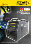
1
2YEARS Warranty
(Power Source)
Lift Arc DC/TIG
15 AMP
240 Volt
Standard
MIG / MAG
OPERATING MANUAL
KMM180
Plasma CUT
Please read and understand this instruction manual carefully
before the installation and operation of this equipment.
1
© Welding Guns Of Australia PTY LTD 2012
• 2 Years from date of purchase.
WARRANTY
• Welding Guns Of Australia PTY LTD Ltd warranties all goods as specified by the manufacturer
of those goods.
• This Warranty does not cover freight or goods that have been interfered with.
• All goods in question must be repaired by an authorised repair agent as appointed by this
company.
• Warranty does not cover abuse, mis-use, accident, theft, general wear and tear.
• New product will not be supplied unless Welding Guns Of Australia PTY LTD has inspected
product returned for warranty and agree’s to replace product.
• Product will only be replaced if repair is not possible
• Please view full Warranty term and conditions supplied with machine or at www.unimig.com.au/
warranty.asp or at the back of this manual.
2
Thank you for your purchase of your UNI-MIG welding machine.
We are proud of our range of welding equipment that has a proven track record of innovation,
performance and reliability.
Our product range represents the latest developments in Mig machine design put together by our
professional team of highly skilled engineers. The expertise gained from our long involvement with
welding machine design has proven to be invaluable towards the evolution and future
development of our equipment range. This experience gives us the inside knowledge on what the
arc characteristics, performance and interface between man and machine should be.
Within our team are specialist welders that have a proven history of welding knowledge and
expertise, giving vital input towards ensuring that our machines deliver control and performance to
the utmost professional level.
We employ an expert team of professional sales, marketing and technical personnel that provide
us with market trends, market feedback and customer comments and requirements. Secondly they
provide a customer support service that is second to none, thus ensuring our customers have
confidence that they will be well satisfied both now and in the future.
UNI-MIG welders are manufactured and compliant with - AS/NZ60974.1 2006 - AS60974-6:2006
guaranteeing you electrical safety and performance.The Mini-Mig 180 has been issued electrical
approval number ESV110294.
3
CONTENTS
PAGE
Technical Data, Product Information
5-6
Safety - Cautions
7-9
Machine Layout Pictogram
10
Installation Operation Cautions
11
Installation & Operation for MMA (stick) Welding
12
MMA (Stick) Welding Information
13-14
Installation & Operation for MIG Welding with Gas
15-16
Wire Feed Drive Roller Selection
17
Wire Installation Set up Guide
18
Installation & Operation for MIG Welding with No Gas
19-20
Installation Guide for Mig Torch Liner Installation
21
Mig Torch and Wire Feeder Set Up Guide for Aluminium Mig Wire
22-23
Installation & Operation for MIG Welding with Spool Gun
24-25
MIG (Metal Inert Gas) Welding
26-27
Basic MIG Welding Guide
28-31
Installation & Operation for DC TIG Welding with Lift Arc
32-33
DC TIG Welding
34-35
Tungsten Electrodes
36-37
24 MIG Torch Parts Breakdown
38-39
SP135 Spool Gun Torch Parts Breakdown
40-41
17VTIG Torch Parts Breakdown
42-43
Mig Welding Shooting Guide
44-45
TIG Welding Shooting Guide
46-47
MMA Welding Trouble Shooting Guide
48
Machine Spare Parts Breakdown
49
Warranty
4
2
UNIMIG 180 MINIMIG
180 Amp MIG Welder
Welds: Steels, Stainless, Cast Iron, Bronze, Aluminium, Copper
15 AMP
Features
•
•
•
•
•
•
•
•
•
•
•
•
Step transformer
30-180 Amp
MIG with Gas and Gasless wire function
1Kg to 5Kg Spools
IP21S rating for environmental/safety protection
Tolerant to variable power supply
6 Step voltage switch
Euro torch connection
Spool Gun Connection
Portable
Thermal overload protection
Compliant to AS/NZ60947.1 Standard
Technical Data
Power Supply / Phases (V-Ph)
Duty Cycle @ 40°c as per AS/NZ60974-1
No Load Voltage (V)
Output Current Range MIG Rated Power MIG
I ieff MIG
Power factor
Protection Class
Insulation Class
Wire Diameter Range (mm)
Dimensions Power Source (LxWxH)
Weight Power Source
Warranty
Certification Approval
240v - 1 +/- 15%
10% @ 180 Amps MIG
21.0
35A/16.0V - 180A/23.0V
4.9 KVA
11.7 Amps
0.72
P 21S
H
0.6, 0.8 Solid Wire
0.8, 0.9 Gasless Wire
480x280x345mm
33 Kg
2 years on power source
AS/NZ60974-1
SPG135
Spool Gun Option
UMJRTROLLEY2
Machine Trolley option
Overview
The UNIMIG 180 is a step transformer portable MIG welding machine. The UNIMIG 180 allows you to MIG weld with both Gas
Shielded and Gasless wire. Easy 6 Step adjustment of voltage and seamless adjustment of the wire feed speed makes for easy setting
of welding parameters giving good quality welding results. An additional feature is the Spoolgun ready function that allows the simple
connection of the optional SPG135 Spoolgun for use with thin or softer wires that don’t have the column strength required to feed
through standard MIG torches, such as aluminium wire. A high quality non-commercial machine, it is compact and portable. An optional
trolley provides off the floor operation and better manoeuvrability around the workshop. Being 240v single phase gives great portability,
it can be run from any 15 Amp power socket providing more flexible use for site and home workshop locations. Suitable for
automotive workshops, light metal fabrication, car repairs, home and hobby use. Designed and built to our specification.
Certified to - AS/NZ60974.1 2006
rweld
zo
W
r S o u rce o
nl
TY
we
y)
Po
(
UN
IM
•
rs arra
ea
y
nt
2Y
SB15 3M Sure Grip MIG Torch, 3M Direct Connect Earth Lead, UNI-FLAME Twin Gauge Argon Regulator,
2M Gas Hose Complete with fittings, 1 x 0.5Kg Spool Solid Wire plus drive roller ,
1 x 0.45Kg Spool Gasless Wire plus drive roller
Ra
MACHINE PACKAGE: KMM180
IG W R R A N
A
5
SAFETY
Welding and cutting equipment can be dangerous to both the operator and people in or near the
surrounding working area, if the equipment is not correctly operated. Equipment must only be
used under the strict and comprehensive observance of all relevant safety regulations.
Read and understand this instruction manual carefully before the installation and operation of this
equipment.
Machine Operating Safety
• Do not switch the function modes while the machine is operating. Switching of the function modes during
welding can damage the machine. Damage caused in this manner will not be covered under warranty.
• Disconnect the electrode-holder cable from the machine before switching on the machine, to avoid arcing
should the electrode be in contact with the work piece.
• Operators should be trained and or qualified.
Electric shock: It can kill. Touching live electrical parts can cause fatal shocks or severe
burns. The electrode and work circuit is electrically live whenever the output is on. The input
power circuit and internal machine circuits are also live when power is on. In Mig/Mag welding,
the wire, drive rollers, wire feed housing, and all metal parts touching the welding wire are
electrically live. Incorrectly installed or improperly grounded equipment is dangerous.
• Connect the primary input cable according to Australian and New Zealand standards and regulations.
• Avoid all contact with live electrical parts of the welding circuit, electrodes and wires with bare hands.
The operator must wear dry welding gloves while he/she performs the welding task.
• The operator should keep the work piece insulated from himself/herself.
• Keep cords dry, free of oil and grease, and protected from hot metal and sparks.
• Frequently inspect input power cable for wear and tear, replace the cable immediately if damaged,
bare wiring is dangerous and can kill.
• Do not use damaged, under sized, or badly joined cables.
• Do not drape cables over your body.
• We recommend (RCD) safety switch is used with this equipment to detect any leakage of current to earth.
Fumes and gases are dangerous. Smoke and gas generated whilst welding or cutting can
be harmful to people’s health. Welding produces fumes and gases. Breathing these fumes and
gases can be hazardous to your health. • Do not breathe the smoke and gas generated whilst welding or cutting, keep your head out of the fumes
• Keep the working area well ventilated, use fume extraction or ventilation to remove welding fumes and
gases.
• In confined or heavy fume environments always wear an approved air-supplied respirator.
Welding fumes and gases can displace air and lower the oxygen level causing injury or death. Be sure the
breathing air is safe.
• Do not weld in locations near de-greasing, cleaning, or spraying operations. The heat and rays of the arc
can react with vapours to form highly toxic and irritating gases.
• Materials such as galvanized, lead, or cadmium plated steel, containing elements that can give off toxic
fumes when welded. Do not weld these materials unless the area is very well ventilated, and or wearing
an air supplied respirator.
Arc rays: harmful to people’s eyes and skin. Arc rays from the welding process produce
intense visible and invisible ultraviolet and infrared rays that can burn eyes and skin.
• Always wear a welding helmet with correct shade of filter lens and suitable protective clothing including
welding gloves whilst the welding operation is performed.
• Measures should be taken to protect people in or near the surrounding working area. Use protective
screens or barriers to protect others from flash,glare and sparks; warn others not to watch the arc.
6
Fire hazard. Welding on closed containers, such as tanks,drums, or pipes, can cause them
to explode. Flying sparks from the welding arc, hot work piece, and hot equipment can cause
fires and burns. Accidental contact of electrode to metal objects can cause sparks, explosion,
overheating, or fire. Check and be sure the area is safe before doing any welding.
• The welding sparks & spatter may cause fire, therefore remove any flammable materials well away from
the working area. Cover flammable materials and containers with approved covers if unable to be moved
from the welding area..
• Do not weld on closed containers such as tanks, drums, or pipes, unless they are properly prepared
according to the required Safety Standards to insure that flammable or toxic vapors and substances are
totally removed, these can cause an explosion even though the vessel has been “cleaned”.
Vent hollow castings or containers before heating, cutting or welding. They may explode.
• Do not weld where the atmosphere may contain flammable dust, gas, or liquid vapours (such as petrol)
• Have a fire extinguisher nearby and know how to use it. Be alert that welding sparks and hot materials
from welding can easily go through small cracks and openings to adjacent areas. Be aware that welding
on a ceiling, floor, bulkhead, or partition can cause fire on the hidden side.
Gas Cylinders. Shielding gas cylinders contain gas under high pressure. If damaged, a cylinder can explode. Because gas cylinders are normally part of the welding process, be sure to
treat them carefully. CYLINDERS can explode if damaged.
• Protect gas cylinders from excessive heat, mechanical shocks, physical damage, slag, open flames,
sparks, and arcs.
•Insure cylinders are held secure and upright to prevent tipping or falling over.
• Never allow the welding electrode or earth clamp to touch the gas cylinder, do not drape welding cables
over the cylinder.
• Never weld on a pressurised gas cylinder, it will explode and kill you.
• Open the cylinder valve slowly and turn your face away from the cylinder outlet valve and gas regulator.
Gas
build up. The build up of gas can causes a toxic environment, deplete the oxygen content
in the air resulting in death or injury. Many gases use in welding are invisible and odourless.
•Shut off shielding gas supply when not in use.
• Always ventilate confined spaces or use approved air-supplied respirator.
Electronic magnetic fields. MAGNETIC FIELDS can affect Implanted Medical Devices.
•Wearers of Pacemakers and other Implanted Medical Devices should keep away.
•Implanted Medical Device wearers should consult their doctor and the device manufacturer before going
near any electric welding, cutting or heating operation.
Noise can damage hearing. Noise from some processes or equipment can damage hearing.
Wear approved ear protection if noise level is high.
Hot parts. Items being welded generate and hold high heat and can cause severe burns.
Do not touch hot parts with bare hands. Allow a cooling period before working on the welding
gun. Use insulated welding gloves and clothing to handle hot parts and prevent burns.
7
CAUTION
1. Working Environment.
1.1 The environment in which this welding equipment is installed must be free of grinding dust, corrosive
chemicals, flammable gas or materials etc, and at no more than maximum of 80% humidity.
1.2 When using the machine outdoors protect the machine from direct sun light, rain water and snow etc;
the temperature of working environment should be maintained within -10°C to +40°C.
1.3 Keep this equipment 30cm distant from the wall.
1.4 Ensure the working environment is well ventilated.
2. Safety Tips.
2.1 Ventilation
This equipment is small-sized, compact in structure, and of excellent performance in amperage output.
The fan is used to dissipate heat generated by this equipment during the welding operation.
Important: Maintain good ventilation of the louvers of this equipment. The minimum distance between
this equipment and any other objects in or near the working area should be 30 cm. Good ventilation is
of critical importance for the normal performance and service life of this equipment.
2.2 Thermal Overload protection.
Should the machine be used to an excessive level, or in high temperature environment, poorly
ventilated area or if the fan malfunctions the Thermal Overload Switch will be activated and the
machine will cease to operate. Under this circumstance, leave the machine switched on to keep the
built-in fan working to bring down the temperature inside the equipment. The machine will be ready for
use again when the internal temperature reaches safe level.
2.3 Over-Voltage Supply
Regarding the power supply voltage range of the machine, please refer to “Main parameter” table.
This equipment is of automatic voltage compensation, which enables the maintaining of the voltage
range within the given range. In case that the voltage of input power supply amperage exceeds the
stipulated value, it is possible to cause damage to the components of this equipment. Please ensure
your primary power supply is correct.
2.4 Do not come into contact with the output terminals while the machine is in operation. An electric shock
may possibly occur.
MAINTENANCE
Exposure to extremely dusty, damp, or corrosive air is damaging to the welding machine. In order to prevent any possible failure or fault of this welding equipment, clean the dust at regular intervals with clean and
dry compressed air of required pressure.
Please note that: lack of maintenance can result in the cancellation of the guarantee; the guarantee of
this welding equipment will be void if the machine has been modified, attempt to take apart the machine or
open the factory-made sealing of the machine without the consent of an authorized representative of the
manufacturer.
TROUBLE SHOOTING
Caution: Only qualified technicians are authorized to undertake the repair of this welding equipment.
For your safety and to avoid Electrical Shock, please observe all safety notes and precautions
detailed in this manual.
Note:
Minimum Motor Generator Power Suggested:- 7KVA for MIG180
8
FRONT PANEL LAYOUT
1.
2.
3.
4.
5.
6.
7.
8.
9.
ON/OFF Power Switch
Wire Speed Adjustment Knob
Thermal Overload Light
Voltage Selecion Knob
SpoolGun Power Supply Connection
Earth Lead
Primary Power Supply Connection
Standard Mig/Spool Gun Selector Switch
Euro Mig Torch Connector (MIG/MAG)
1
2
8
3
4
5
9
6
7
BACK PANEL LAYOUT
10. Gas Inlet
11. Fan
12. Data Plate
10
11
12
14
13
INTERNAL PANEL LAYOUT
13. DC Positive output terminal
14. DC Negative output terminal
15. Wire feeder mechanism
16. Spool holder assembly
16
15
9
INSTALLATION & OPERATION
Please install the machine strictly according to the following steps.
The protection class of this machine is IP21S, so avoid using it in rain.
Connection of Input Cables
Primary input cable is supplied with this welding equipment. Connect the primary input cable with power
supply of required input voltage. Refer to data plate on machine for Input voltage, IMAX and IEFF.
10
Installation set up for MIG with Gas for UNI-MIG MIG180
(1) Plug Primay power supply cable into 15amp power outlet.
(2) Select Standard MIG using the Standard/Spool Gun selector switch.
(3) Plug the welding torch into the Euro Mig torch connection socket on the front panel, and tighten it.
IMPORTANT : When connecting the torch be sure to tighten the connection. A loose connection can
result in the connector arcing and damaging the machine and gun connector.
This damage is not covered under warranty.
(4) Connect earth lead to the workpiece.
(5) Connect Gas Line to Gas Regulator and connect the gas regulator to the Gas Cylinder.
(6) Connect the weld power cable plug inside the wire feeder to the output socket GAS, and tighten it.
(7) Place the Wire Spool onto the Spool Holder - Note: the spool retaining nut is Left Hand thread.
Snip the wire from the spool being sure to hold the wire to prevent rapid uncoiling. Feed the wire into
the wire feeder inlet guide tube through to the drive roller.
(8) Carefully feed the wire over the drive roller into the outlet guide tube, feed through about 150mm into
the torch receptacle. Check that the drive roller being used complies with the wire diameter, replace the
roller if necessary.
(5) Connect the gas line to the regulator
and connect to the gas cylinder
(3) Connect Mig torch
IMPORTANT : When connecting the torch
be sure to tighten the connection.
(2) Set Standard/Spoolgun
selector switch to Standard
(4) Connect earth lead to
workpiece
(6) Connect weld power lead to GAS
as show in picture inside machine
(1) Plug Primay power supply cable
into 15amp power outlet.
(7) Place wire onto spool holder - (spool
retaining nut is left hand thread ) Feed the wire
through the inlet guide tube on to the drive
roller.
(8) Feed wire over the drive roller into the outlet
guide tube, Push the wire through approx
150mm.
11
Continued set up for MIG with Gas for UNI-MIG MIG180
(9) Align the wire into the groove of the drive roller and close down the top roller making sure the wire is in
the groove of the bottom drive roller, lock the pressure arm into place.
(10) Apply a medium amount of pressure to the drive roller.
(11) Remove the gas nozzle and contact tip from the torch neck,
(12) Press and hold the trigger on the mig torch until wire is visable at the tip holder
(13) Fit the correct sized contact tip and feed the wire through it, screw the contact tip into the tip holder of
the torch head and nip it up tightly.
(14) Fit the gas nozzle to the torch head.
(15) Carefully open the gas cylinder valve and set the flow rate to between 5-10 l/min.
(16) Set the welding parameters using the wire feed and voltage control knobs.
(9) Close down the top roller bracket and clip
the pressure arm into place.
(10) Apply a medium amount of
pressure to the drive roller
(11) Remove the gas nozzle and contact tip
from the front end of the mig torch.
(12) Press and hold the trigger on the mig
torch until wire is visable at the tip holder.
(13) Fit the correct size contact tip over
the wire and fasten tightly into the tip
holder.
(14) Fit the gas nozzle to the torch head.
(15) Carefully open the valve of the gas
cylinder, set the flow to 10 l/min
12
(16) Set welding parameters using the
voltage and wire feed controls.
Wire Feed Roller Selection
The importance of smooth consistent wire feeding during MIG welding cannot be emphasized enough.
Simply put the smoother the wire feed then the better the welding will be.
Feed rollers or drive rollers are used to feed the wire mechanically along the length of the welding gun.
Feed rollers are designed to be used for certain types of welding wire and they have different types of
grooves machined in them to accommodate the different types of wire. The wire is held in the groove by
the top roller of the wire drive unit and is referred to as the pressure roller, pressure is applied by a tension
arm that can be adjusted to increase or decrease the pressure as required. The type of wire will determine
how much pressure can be applied and what type of drive roller is best suited to obtain optimum wire feed.
Solid Hard Wire - like Steel, Stainless Steel require a drive roller with a V shape groove for optimum grip
and drive capability. Solid wires can have more tension applied to the wire from the top pressure roller that
holds the wire in the groove and the V shape groove is more suited for this. Solid wires are more forgiving
to feed due to their higher cross sectional column strength, they are stiffer and don’t bend so easy.
Soft Wire - like Aluminium requires a U shape groove. Aluminium wire has a lot less column strength, can
bend easily and is therefore more difficult to feed. Soft wires can easily buckle at the wire feeder where the
wire is fed into inlet guide tube of the torch. The U-shaped roller offers more surface area grip and traction
to help feed the softer wire. Softer wires also require less tension from the top pressure roller to avoid deforming the shape of the wire, too much tension will push the wire out of shape and cause it to catch in the
contact tip.
Flux Core / Gasless Wire - these wires are made up of a thin metal sheath that has fluxing and metal
compounds layered onto it and then rolled into a cylinder to form the finished wire. The wire cannot take
too much pressure from the top roller as it can be crushed and deformed if too much pressure is applied.
A knurled drive roller has been developed and it has small serrations in the groove, the serrations grip the
wire and assist to drive it without too much pressure from the top roller. The down side to the knurled wire
feed roller on flux cored wire is it will slowly over time bit by bit eat away at the surface of the welding wire,
and these small pieces will eventually go down into the liner. This will cause clogging in the liner and added
friction that will lead to welding wire feed problems. A U groove wire can also be used for flux core wire
without the wire particles coming of the wire surface. However it is considered that the knurled roller will
give a more positive feed of flux core wire without any deformation of the wire shape.
Top Pressure Roller
Top Pressure Roller
V Groove
U Groove
Wire
Wire
Knurled Groove
Wire
V Groove Drive Roller - Steel Wire
Part Number
0.6-0.8V30/10
0.8-0.9V30/10
Description
Drive Roll V Groove 0.6-0.8mm
Drive Roll V Groove 0.8-0.9mm
10mm
Drive Rollers
Top Pressure Roller
U Groove Drive Roller - Soft Wire
30mm
Part Number
0.6-0.8U30/10
0.8-0.9U30/10
Description
Drive Roll U Groove 0.6-0.8mm
Drive Roll U Groove 0.8-0.9mm
10mm
Knurled Drive Roller - Flux Core Wire
Part Number
0.6-0.8F30/10
0.8-0.9F30/10
Description
Drive Roll V Groove 0.6-0.8mm
Drive Roll V Groove 0.8-0.9mm
13
Wire Installation and Set Up Guide
Again the importance of smooth consistent wire feeding during MIG welding cannot be emphasized enough.
The correct installation of the wire spool and the wire into the wire feed unit is critical to achieving an even
and consistent wire feed. A high percentage of faults with mig welders emanate from poor set up of the wire
into the wire feeder. The guide below will assist in the correct setup of your wire feeder.
(1) Remove the spool retaining nut.
(2) Note the tension spring adjuster
and spool locating pin.
(4) Snip the wire carefully, be sure to hold the
wire to prevent the spool uncoiling. Carefully
feed the wire into the inlet guide tube of the
wire feed unit.
(5) Feed the wire through the drive roller and
into the outlet guide tube of the wire feeder.
(7) Check that the wire passes through
the centre of the outlet guide tube without
touching the sides. Loosen the locking
screw and then loosen the outlet guide
tube retaining nut too make adjustment if
required. Carefully retighten the locking nut
and screw to hold the new position.
14
(8) A simple check for the correct drive tension
is to bend the end of the wire over hold it about
100mm from your hand and let it run into your
hand, it should coil round in your hand without
stopping and slipping at the drive rollers,
increase the tension if it slips.
(3) Fit the wire spool onto the spool holder
fitting the locating pin into the location hole
on the spool. Replace the spool retaining
nut tightly
(6) Lock down the top pressure roller and
apply a medium amount of pressure using the tension adjustment knob
(8) The weight and speed of the wire spool
turning creates an inertia that can cause the
spool to run on and the wire loop over the
side of the spool and tangle. if this happens
increase the pressure on the tension spring
inside the spool holder assembly using the
tension adjustment screw.
Installation set up for MIG with Gasless wire for UNI-MIG MIG180
(1) Plug Primay power supply cable into 15amp power outlet.
(2) Select Standard MIG using the Standard/Spool Gun selector switch.
(3) Plug the welding torch into the Euro Mig torch connection socket on the front panel, and tighten it.
IMPORTANT : When connecting the torch be sure to tighten the connection. A loose connection can
result in the connector arcing and damaging the machine and gun connector.
This damage is not covered under warranty.
(4) Connect earth lead to the workpiece.
(5) Connect the weld power cable plug inside the wire feeder to the output socket NO GAS, and tighten it.
(6) Fit the correct sized Knurled Drive roller for Gas Less Flux Cored wire
(7) Place the Wire Spool onto the Spool Holder - Note: the spool retaining nut is Left Hand thread.
Snip the wire from the spool being sure to hold the wire to prevent rapid uncoiling. Feed the wire into
the wire feeder inlet guide tube through to the drive roller.
(3) Connect Mig torch
IMPORTANT : When connecting the torch
be sure to tighten the connection.
(2) Set Standard/Spoolgun
selector switch to Standard
(1) Plug Primay power supply cable
into 15amp power outlet.
(4) Connect earth lead to
workpiece
(5) Connect weld power lead to
NO GAS
as show in picture inside machine
(7) Fit the correct sized Knurled
Drive roller for Gas Less Flux
Cored wire
(7) Place wire onto spool holder - (spool
retaining nut is left hand thread ) Feed the wire
through the inlet guide tube on to the drive
roller.
15
Continued set up for MIG with Gasless wire for UNI-MIG MIG180
(8) Carefully feed the wire over the drive roller into the outlet guide tube, feed through about 150mm into
the torch receptacle. Check that the drive roller being used complies with the wire diameter, replace
the roller if necessary.
(9) Align the wire into the groove of the drive roller and close down the top roller making sure the wire is in
the groove of the bottom drive roller, lock the pressure arm into place.
(10) Apply a medium amount of pressure to the drive roller.
(11) Remove the gas nozzle and contact tip from the torch neck,
(12) Press and hold the trigger on the mig torch until wire is visable at the tip holder
(13) Fit the correct sized contact tip and feed the wire through it, screw the contact tip into the tip holder of
the torch head and nip it up tightly.
(14) Fit the gas nozzle to the torch head.
(15) Set the welding parameters using the wire feed and voltage control knobs.
(8) Feed wire over the drive roller into
the outlet guide tube, Push the wire
through approx 150mm. Use a Knurled
Drive Roller of the correct size
(9) Close down the top roller bracket and clip
the pressure arm into place.
(11) Remove the gas nozzle and contact tip
from the front end of the mig torch.
(12) Press and hold the inch wire button to
feed the wire down the torch cable through
to the torch head.
(14) Fit the gas nozzle to the torch head.
16
(15) Set welding parameters using the
voltage and wire feed controls.
(10) Apply a medium amount of
pressure to the drive roller
(13) Fit the correct size contact tip over
the wire and fasten tightly into the tip
holder.
Mig Torch Liner Installation
(1)
(2)
(3)
(4)
(5)
(6)
(7)
(8)
(9)
Lay the torch out straight on the ground and remove the front end parts
Remove the liner retaining nut.
Carefully pull the liner out of the torch cable assembly
Select the correct new liner and carefully unravel avoiding putting any kinks in the liner, if you kink the
liner it will make it no good and will require replacement.
Carefully and slowly feed the liner in short forward movements down the cable assembly all the way
through and out the torch neck end. Avoid kinking the liner, kinking liner it will make it no good and
require replacement.
Fit the liner retaining nut and screw down only 1/2 way
Leaving the torch straight snip the liner approximately 3mm past the end of the torch neck
Place the tip holder over the end of the liner and screw into the torch neck nipping it up tight.
Screw down the liner nut the remaining 1/2 and nip it up tight. This method compresses the liner
inside the torch cable assembly preventing it moving during use and ensures good wire feed.
(1) Remove mig torch front end parts
(2) Remove the liner retaining nut
(3) Carefully pull out and completely
remove the liner
(4) Carefully unravel the new liner
(5) Carefully feed in the new liner down
the torch lead all the way to exit the torch
neck.
(6) Fit the liner retaining nut and screw
only 1/2 way down
(7) Snip the liner off 3mm past the end
of the torch neck.
(8) Replace the front end parts
(9) Fully screw down the liner retaining
nut and nip it up tight.
17
Torch & Wire Feed Set Up for Aluminium Wire
(1)
(2)
(3)
(4)
(5)
(5)
(8)
(9)
18
Lay the torch out straight on the ground and remove the front end parts
Remove the liner retaining nut.
Carefully pull the liner out of the torch cable assembly
Select a PA or liner, carefully and slowly feed the liner in short forward movements down the cable
assembly all the way through and out the torch neck end. Avoid kinking the liner, kinking the liner will
ruin it and require replacement.
Leave the liner extending out the end of the torch neck end by 3mm.
Fit the liner retaining nut together with the liner o-ring.
Push the liner firmly into the torch lead and tighten the liner retaining nut.
Install a U groove drive roller of the correct size to match the wire diameter being used.
(1) Remove mig torch front end parts
(2) Remove the liner retaining nut
(4) Carefully unravel the new liner
(5) Carefully feed in the new liner in short
forward movements down the torch lead
all the way to exit the torch neck. Be careful not to kink the liner
(6) Replace the front end parts
(7) Fit the liner collet, liner O-ring and
liner retaining nut.
(8) Push the liner firmly into the torch lead
and tighten the liner retaining nut
(9) Install a U groove drive roller of the
correct size for the diameter wire being
used.
(3) Carefully pull out and completely
remove the liner
Continued Torch & Wire Feed Set Up for Aluminium Wire
(10) Remove circlip from guide tube.
(11) Remove the inlet guide tube from the front end machine euro connector using long nose pliers.
(12) Carefully feed the extended PA liner section into the inlet guide tube hole of the machine euro
connector
(13) Feed the extended PA liner all the way up and over the drive roller
(14) Tighten the torch euro connection to the machine euro connector
(15) Cut the extended liner with a sharp Stanley knife just in front of the drive roller
(16) Fit an Aluminium contact tip of the correct size to match the diameter of the wire being used
(17) Fit the remaining front end parts to the torch neck ready for welding
(10) Remove circlip from guide tube.
(11 Remove the inlet guide tube using long
nose pliers.
(12) Carefully feed the PA liner into the
inlet guide tube hole of the torch euro
receptacle
(13)Take the extended PA liner all the way up
and over the drive roller
(14 Tighten and secure the torch euro
connector to the machine euro receptacle
(15) Cut the extended PA liner with a
sharp Stanley knife just in front of the drive
roller
(16) Fit an Aluminium contact tip of the
correct size to match the wire diameter
being used
(17) Fit the remaining front end parts to the
torch neck ready for welding.
19
Installation set up of the Spool Gun for UNI-MIG MIG180
(1)
(2)
(3)
(4)
(5)
(6)
(7)
(8)
(9)
Plug Primay power supply cable into 15amp power outlet.
Switch on the machine,
Select Spool Gun using the Standard/Spool Gun selector switch.
Connect the Spool Gun to the Euro Mig torch connection socket on the front panel, and tighten it.
Connect the Spool Gun control cable to the receptacle and tighten it.
IMPORTANT : When connecting the torch be sure to tighten the connection. A loose connection can
result in the connector arcing and damaging the machine and gun connector.
This damage is not covered under warranty.
Connect earth lead to the workpiece.
Connect Gas Line to Gas Regulator and connect the gas regulator to the Gas Cylinder.
Connect weld power lead to GAS
Remove wire from the drive unit as show in picture inside
machine
Take the Spool Gun and remove the spool cover.
Place the Wire Spool onto the Spool Holder - Hold and snip the wire from the spool being sure to
hold the wire to prevent rapid uncoiling.
(6) Connect the gas line to the regulator
and connect to the gas cylinder
(4) Connect Spool Gun control cable and
gun cable connector
(2) Switch on the machine
IMPORTANT : When connecting the torch
be sure to tighten the connection.
(3) Set Standard/Spoolgun
selector switch to Spool Gun
(5) Connect earth lead to
the workpiece
(1) Plug Primay power supply cable
into 15amp power outlet.
(7)Connect weld power lead to GAS
Remove wire from the drive unit
as show in picture inside machine
20
(8) Remove the spool cover by
unscrewing the retaining nut and lifting
off the cover
(9) Place a spool of wire onto the Spool
holder.
Continued set up of the Spool Gun for UNI-MIG MIG180
(10) Carefully feed the wire through the red guide tube into meet the drive roller. Push down the tension
arm adjustment lever to release the drive roll pressure allowing the wire to be guided through the drive
rollers into the gun neck.
(11) Replace the spool cover
(12) Remove the gas nozzle and contact tip from the torch neck, Pull the trigger to drive the wire through
the neck until it exits the contact tip holder.
(13) Fit the correct sized contact tip by feeding the wire through it, screw the contact tip into the tip holder
of the torch neck and nip it up tightly.
(14) Check the drive roll pressure is enough to drive the wire smoothly and adjust the drive roll pressure if
required by using the adjusting screw at the top of the torch body. Do not apply too much pressure.
(15) Fit the gas nozzle to the torch head.
(16) Carefully open the gas cylinder valve and set the flow rate to between 8-12 l/min.
(17) Set the welding parameters using the wire feed and voltage control knobs.
(10) Carefully feed the wire through the inlet
guide tube onto the drive roller through into
the outlet guide tube. Push down the tension
arm lever to release the pressure of the drive
roller allowing the wire to be guided through
the drive roller into the gun neck.
(13) Fit the contact tip over the wire and
screw it into the tip holder, nip it up tight.
(11) Replace the Spool Cover.
(14) Adjust the drive roll pressure if required
by using the adjusting screw at the top of the
torch.
(16) Carefully open the valve of the gas
cylinder, set the flow to 8-12 l/min
(12) Remove the gas nozzle and contact tip.
Pull the trigger to drive the wire through the
neck until it exits the contact tip holder
(15) Fit the gas nozzle ready for welding.
(17) Set welding parameters using the
voltage and wire feed controls.
21
MIG (Metal Inert Gas) Welding
Definition of MIG Welding - MIG (metal inert gas) welding also known as GMAW (gas metal arc
welding) or MAG (metal active gas welding), is a semi-automatic or automatic arc welding process
in which a continuous and consumable wire electrode and a shielding gas are fed through a welding gun. A constant voltage, direct current power source is most commonly used with MIG welding.
There are four primary methods of metal transfer in MIG welding, called short circuit (also known as
dip transfer) globular transfer, spray transfer and pulsed-spray, each of which has distinct properties
and corresponding advantages and limitations. To perform MIG welding, the basic necessary equipment is a welding gun, a wire feed unit, a welding power supply, an electrode wire, and a shielding
gas supply. Short circuit transfer is the most common used method whereby the wire electrode is
fed continuously down the welding torch through to and exiting the contact tip. The wire touches the
work piece and causes a short circuit the wire heats up and begins to form a molten bead, the bead
separates from the end of the wire and forms a droplet that is transferred into the weld pool. This
process is repeated about 100 times per second, making the arc appear constant to the human eye.
MIG Circuit Diagram
5
6
4
1
2
3
1. Mig Torch - 2. Work Piece - 3. Power Source - 4. Wire Feeder - 5. Wire Spool - 6. Gas
22
MIG (Metal Inert Gas) Welding
Short Circuit Transfer - Short circuit transfer is the most common used method whereby the wire
electrode is fed continuously down the welding torch through to and exiting the contact tip. The
wire touches the work piece and causes a short circuit the wire heats up and begins to form a
molten bead, the bead separates from the end of the wire and forms a droplet that is transferred
into the weld pool. This process is repeated about 100 times per second, making the arc appear
constant to the human eye.
short circuit
The wire approaches the work
piece and touches the work creating a short circuit between the
wire and the base metal, because
there is no space between the wire
and the base metal there is no arc
and current flows through the wire.
droplet
separates
The pinch causes the forming
droplet to separate and fall towards the now creating weld pool.
wire heating
The wire cannot support all the
current flow, resistance builds
up and the wire becomes hot
and weak and begins to melt
arc flattens
the droplet
An arc is created at the separation
of the droplet and the heat and force
of the arc flattens out the droplet
into the weld pool. The heat of the
arc melts the end of the wire slightly
as it feeds towards the base metal
magnetic
field pinches
wire
The current flow creates a magnetic field that begins to pinch the
melting wire forming it into droplet
cycle
repeats
The wire feed speed overcomes
the heat of the arc and the wire
again approaches the work to
short circuit and repeat the cycle.
23
Basic MIG Welding .
Good weld quality and weld profile depends on gun angle, direction of travel, electrode extension
(stick out), travel speed, thickness of base metal, wire feed speed (amperage) and arc voltage.
To follow are some basic guides to assist with your setup.
Gun Position - Travel Direction, Work Angle
Gun position or technique usually refers to how the wire is directed at the base metal, the angle
and travel direction chosen. Travel speed and work angle will determine the characteristic of the
weld bead profile and degree of weld penetration.
Push Technique - The wire is located at the leading edge of the weld pool and pushed towards
the un-melted work surface. This technique offers a better view of the weld joint and direction of
the wire into the weld joint. Push technique directs the heat away from the weld puddle allowing
faster travel speeds providing a flatter weld profile with light penetration - useful for welding thin
materials. The welds are wider and flatter allowing for minimal clean up / grinding time.
Perpendicular Technique - The wire is fed directly into the weld, this technique is used primarly for automated situations or when conditions make it necessary. The weld profile is generally
higher and a deeper penetration is achieved.
Drag Technique - The gun and wire is dragged away from the weld bead. The arc and heat is
concentrated on the weld pool, the base metal receives more heat, deeper melting, more penetration and the weld profile is higher with more build up.
(A) Push Technique
(B) Gun Perpendicular
(C) Drag Technique
10°
10°
travel direction
travel direction
wire pointed ahead of bead
flat even weld profile
light penetration
24
travel direction
wire pointed back into bead
narrower weld profile
even penetration
narrow higher weld profile
more penetration
Travel Angle - Travel angle is the right to left angle relative to the direction of welding. A travel
angle of 5°- 15° is ideal and produces a good level of control over the weld pool. A travel angle
greater that 20° will give an unstable arc condition with poor weld metal transfer, less penetration,
high levels of spatter, poor gas shield and poor quality finished weld.
Not enough angle
Angle 5°- 15°
good level of control over the
weld pool, even flat weld
Angle more than 20°
less control over the weld pool
more spatter
poor control, unstable arc, less
penetration, lots of spatter
Angle to Work - The work angle is the forward back angle of the gun relative to the work piece.
The correct work angle provides good bead shape, prevents undercut, uneven penetration, poor
gas shield and poor quality finished weld.
Not enough angle
Correct angle
good level of control over the
weld pool, even flat weld
less control over the weld pool
more spatter
Too much angle
poor control, unstable arc, less
penetration, lots of spatter
Stick Out- Stick out is the length of the unmelted wire protruding from the end of the contact tip.
A constant even stick out of 5-10mm will produce a stable arc, and an even current flow providing
good penetration and even fusion. Too short stick out will cause an unstable weld pool, produce
spatter and over heat the contact tip. Too long stick out will cause an unstable arc, lack of penetration, lack of fusion and increase spatter.
Normal stick out
Too short
Too long
5-10mm
Even arc, good penetration
even fusion, good finish
Unstable arc, spatter, over
heat contact tip
Unstable arc, spatter, poor
penetration and fusion
25
Travel Speed - Travel speed is the rate that the gun is moved along the weld joint and is usually
measured in mm per minute. Travel speeds can vary depending on conditions and the welders
skill and is limited to the welders ability to control the weld pool. Push technique allows faster
travel speeds than Drag technique. Gas flow must also correspond with the travel speed, increasing with faster travel speed and decreasing with slower speed. Travel speed needs to match the
amperage and will decrease as the material thickness and amperage increase.
Too Fast Travel Speed - A too fast travel speed produces too little heat per mm of travel resulting
in less penetration and reduced weld fusion, the weld bead solidifies very quickly trapping gases
inside the weld metal causing porosity. Undercutting of the base metal can also occur and an unfilled groove in the base metal is created when the travel speed is too fast to allow molten metal to
flow into the weld crater created by the arc heat.
high narrow bead
Too Fast Travel Speed
porosity
undercut
spatter
lack of fusion
lack of joint penetration
Too Slow Travel Speed - A too slow travel speed produces a large weld with lack of penetration
and fusion. The energy from the arc dwells on top of the weld pool rather than penetrating the
base metal. This produces a wider weld bead with more deposited weld metal per mm than is
required resulting in a weld deposit of poor quality.
Too Slow Travel Speed
large wide bead
porosity
lack of fusion
cold lap
lack of joint penetration
Correct Travel Speed - The correct travel speed keeps the arc at the leading edge of the weld
pool allowing the base metal to melt sufficiently to create good penetration, fusion and wetting out
of the weld pool producing a weld deposit of good quality.
Correct Travel Speed
even shaped bead
good side wall fusion
26
good toe fusion
good penetration
Wire types and sizes - Use the correct wire type for the base metal being welded. Use stainless
steel wire for stainless steel, aluminium wires for aluminium and steel wires for steel.
Use a smaller diameter wire for thin base metals. For thicker materials use a larger wire diameter
and larger machine, check the recommended welding capability of you machine.
As a guide refer to the “Welding Wire Thickness Chart” below.
WELDING WIRE DIAMETER CHART
RECOMMENDED WIRE DIAMETERS
MATERIAL
THICKNESS
MIG SOLID WIRE
0.6mm
0.8mm
0.9mm
GASLESS FLUX CORED WIRE
1.0mm
0.8mm
0.9mm
1.2mm
24 Gauge (.60mm)
22 Gauge (.75mm)
20 Gauge (.90mm)
18 Gauge (1.0mm)
16 Gauge (1.2mm)
14 Gauge (1.9mm)
3.0mm
5.0mm
6.0mm
8.0mm
10.mm
12.0mm
For material thickness of 5.0mm and greater, multi-pass runs or a beveled joint
design may be required depending on the amperage capability of your machine.
Gas selection - The purpose of the gas in the MIG process is to protect / shield the wire, the arc
and the molten weld metal from the atmosphere. Most metals when heated to a molten state will
react with the air in the atmosphere, without the protection of the shielding gas the weld produced
would contain defects like porosity, lack of fusion and slag inclusions. Additionally some of the gas
becomes ionised (electrically charged) and helps the current flow smoothly.
The correct gas flow is also very important in protecting the welding zone from the atmosphere.
Too low flow will give inadequate coverage and result in weld defects and unstable arc conditions.
Too high flow can cause air to be drawn into the gas column and contaminate the weld zone.
Use the correct shielding gas. Co2 is good for steel and offers good penetration characteristics,
the weld profile is narrower and slightly more raised than the weld profile obtained from Argon Co2
mixed gas. Argon Co2 mix gas offers better weld ability for thin metals and has a wider range of
setting tolerance on the machine. Argon 80% Co2 20% is a good all round mix suitable for most
applications.
Argon Co2
Co2
Penetration Pattern for Steel
27
Suregrip Series
SB15 MIG TORCH
180A AIR COOLED MIG WELDING TORCH
Rating:180A CO² 150A mixed gas EN60974-7 @ 60% duty cycle. 0.6 to 1.0mm wires
*
Wear parts next page
*
Wear parts next page
Torch Model
Description
SB Suregrip Ergo Torch Package
Part Number
3 Mt
4 Mt
5 Mt
SB15-3M
SB15-4M
SB15-5M
Spare Parts
1
2
3
4
5
6
7
8
9
10
28
Part Number
GNS15
SNK15
SNKF15
UB2501/5
UB2519
UG1515
UB1505
UB1521
UB1521-C
UG8015
UB1517-30
UB1517-40
UB1517-50
Description
Shroud Spring Swan Neck Assembly
Flexible Swan Neck End Fitting Ring Hexagonal Fitting Ergo Handle Location Body Lock Nut Cable Terminal Cable Terminal Cover Handle Cable Support C/W Ball Joint Hyperflex Cable Assembly x 3mt Hyperflex Cable Assembly x 4mt
Hyperflex Cable Assembly x 5mt 11
12
13
14
15
16
17
18
19
20
21
22
Part Number
UG2514
UG2516
UB2517
UB1522
UPA2041
UB1518
UB1541
UB1519PL
UB1523
UC1528
UB1524
UB1525
Description
Ergo Handle Kit C/W Lock Nut Medium / Large Ergo Trigger Hanger Hook Cable Terminal Male
Cable Support Gun Plug Housing C/W Nut Gun Plug Screw Gun Plug Nut Gun Plug Terminal Female Hybrid Gun Plug Body C/W Spring Pins Gun Plug ‘O’ Ring Liner Nut
Suregrip Series
SB15 MIG TORCH
Front end consumables
SB15 Contact Tips
Ø 6.0
M6 x 1.0
Part Number
PCT0008-06
PCT0008-08
PCT0008-09
PCT0008-10
PCTAL0008-09
PCTAL0008-10
M6 x 1.0
M8 x 1.0-L
25.0
Part Number
PCTH15
PGNS15
Ø 12.5
Bore
QTY10
QTY10
QTY10
QTY10
QTY10
QTY10
Description
Contact Tip Holder (Suit SB15)
Shroud Spring
QTY2
QTY2
SB15 Tip Holder
42.0
Ø 18.0
Description
Contact Tip Steel (0.6mm)
Contact Tip Steel (0.8mm)
Contact Tip Steel (0.9mm)
Contact Tip Steel (1.0mm)
Contact Tip Aluminium (0.9mm)
Contact Tip Aluminium (1.0mm)
53.0
Liners
SB15 Gas Nozzle
Part Number
PGN15CYL
PGN15CON
PGN15TAP
PGN15SPOT
Description
Cylindrical Nozzle
Conical Nozzle
Tapered Nozzle
Spot Nozzle
QTY2
QTY2
QTY2
QTY2
SB15 Liners
Part Number
SLB3M
SLB4M
SLB5M
SLR3M
SLR4M
SLR5M
TLB3M
TLB4M
TLR3M
TLR4M
NKSTL
Description
Blue Steel Liner 3 Metre
Blue Steel Liner 4 Metre
0.6 - 0.8mm
Blue Steel Liner 5 Metre
Red Steel Liner 3 Metre
Red Steel Liner 4 Metre
0.9 - 1.2mm
Red Steel Liner 5 Metre
Blue Aluminium Liner 3 Metre
0.6 - 0.8mm
Blue Aluminium Liner 4 Metre
Red Aluminium Liner 3 Metre
0.9 - 1.2mm
Red Aluminium Liner 4 Metre
Neck Spring for Aluminium
}
}
}
}
These parts are manufactured in China and are offered as
replacement parts suitable for “BINZEL®” style torches.
29
SPG135 AMP SPOOL GUN
Duty
Cycle 30%
@ 135Amp
L135YE
SPOOL
GUN
Description
Part Number
XcelArc Spool Gun SPG135 x 6m
SPG135
Spare Parts
1
2
3
4
5
6
7
8
9
10
11
12
13
14
15
16
17
18
30
Part Number
Description
LGJ2003
LMH2001
LMT2001
LMT2016
LMT2015
LMT2014
LMT2013
LMT2012
LMT2011
LGH2011
LGX2016U
LGX2015
LGX2014
LGX2012
LGX2011
LGF2111
LX1040
LMX2011
Trigger
Handle
Spool Cover Total Assembly
Spool Cover Shell
Spool Shaft
Rubber Resistance Bush
Locating Bush
Adjusting Nut
Locking Screw
Drive Roll Cover
Pressure Roll U Groove 0.8-0.9mm
Bearing
Pressure Arm with Shaft
Pressure Arm Spring
Pressure Arm Bolt
Nut
Gear Box Assembly
Inlet Guide
19
20
21
22
23
24
25
26
27
28
29
30
31
32
33
34
35
36
Part Number
Description
LGX2018
LGX2019U
LZ3603
LYFE1001
SEE PAGE 41
SEE PAGE 41
SEE PAGE 41
LYFE1011
LW0101
LGK2011
LYH1012
LYH1013
LYL1640
ES2001
EH2201
EP3001
LTU2202
LMV0004
Key
DriveRoll U Groove 0.8-0.9mm
Motor
Gun Neck
Gas Nozzle
Contact Tip
Diffuser Tip Holder with Spring
Gun Neck Body
Gas Hose
Conducting Board
Cable Support
Handle Nut
Cable Assembly 4m
Cable Support Spring
Cable Support Cover
Euro Connector Nut
Euro Connector Plug
4 Pin Plug
SPG135 AMP SPOOL GUN
Duty Cycle 30% @ 135Amp
Front end consumables
SPG135 Contact Tips
Ø 6.0
M6 x 1.0
Part Number
PCT0008-06
PCT0008-08
PCT0008-09
PCT0008-10
PCTAL0008-09
PCTAL0008-10
M6 x 1.0
M8 x 1.0-L
25.0
Description
Contact Tip Steel (0.6mm) Contact Tip Steel (0.8mm)
Contact Tip Steel (0.9mm)
Contact Tip Steel (1.0mm)
Contact Tip Aluminium (0.9mm)
Contact Tip Aluminium (1.0mm)
SPG135 Tip Holder
Part Number
PCTH15
Description
Contact Tip Holder
Ø 12.5
Bore
Ø 18.0
42.0
53.0
SPG135 Gas Nozzle
Part Number
PGN15CYL
PGN15CON
PGN15TAP
Description
Cylindrical Nozzle
Conical Nozzle
Tapered Nozzle
U Groove Drive Roller - Soft Wire
Part Number
Description
LGX2019U
DriveRoll U Groove 0.8-0.9mm
31
MIG WELDING TROUBLE SHOOTING
The following chart addresses some of the common problems of MIG welding. In all cases of equipment malfunction, the manufacturer’s recommendations should be strictly adhered to and followed.
1: Excessive Spatter
Possible Reason
Suggested Remedy
Wire feed speed set too high
Select lower wire feed speed
Voltage too high
Select a lower voltage setting
Wrong polarity set
select the correct polarity for the wire being used - see machine setup guide
Stick out too long
Bring the torch closer to the work
Contaminated base metal
Remove materials like paint, grease, oil, and dirt, including mill scale from base metal
Contaminated mig wire
Use clean dry rust free wire. Do not lubricate the wire with oil, grease etc
Inadequate gas flow or too much gas Check the gas is connected, check hoses, gas valve and torch are not restricted. Set
flow
the gas flow between 6-12 l/min flow rate. Check hoses and fittings for holes, leaks etc
Protect the welding zone from wind and drafts
2: Porosity - small cavities or holes resulting from gas pockets in weld metal.
Possible Reason
Suggested Remedy
Wrong gas
Check that the correct gas is being used
Inadequate gas flow or too much gas Check the gas is connected, check hoses, gas valve and torch are not restricted. Set the
flow
gas flow between 10 - 15 l/min flow rate. Check hoses and fittings for holes, leaks etc.
Protect the welding zone from wind and drafts
Moisture on the base metal
Remove all moisture from base metal before welding
Contaminated base metal
Remove materials like paint, grease, oil, and dirt, including mill scale from base metal
Contaminated mig wire
Use clean dry rust free wire. Do not lubricate the wire with oil, grease etc
Gas nozzle clogged with spatter,
worn or out of shape
Clean or replace the gas nozzle
Missing or damaged gas diffuser
Replace the gas diffuser
Mig torch euro connect o-ring missing or damaged
check and replace the o-ring
4: Wire stubbing during welding
Possible Reason
Suggested Remedy
Holding the torch too far away
Bring the torch closer to the work and maintain stick out of 5-10mm
Welding voltage set too low
Increase the voltage
Wire Speed set too high
Decrease the wire feed speed
5: Lack of Fusion − failure of weld metal to fuse completely with base metal or a proceeding weld bead.
Possible Reason
Suggested Remedy
Contaminated base metal
Remove materials like paint, grease, oil, and dirt, including mill scale from base metal
Not enough heat input
Select a higher voltage range and /or adjust the wire speed to suit
Improper welding technique
Keep the arc at the leading edge of the weld pool.
Gun angle to work should be between 5 & 15°
Direct the arc at the weld joint
Adjust work angle or widen groove to access bottom during welding
Momentarily hold arc on side walls if using weaving technique
5: Excessive Penetration − weld metal melting through base metal
Possible Reason
Suggested Remedy
Too much heat
Select a lower voltage range and /or adjust the wire speed to suit
Increase travel speed
6: Lack of Penetration − shallow fusion between weld metal and base metal
32
Poor in incorrect joint preparation
Material too thick. Joint preparation and design needs to allow access to bottom of
groove while maintaining proper welding wire extension and arc characteristics
Keep the arc at the leading edge of the weld pool and maintain the gun angle at
5 & 15° keeping the stick out between 5-10mm
Not enough heat input
Select a higher voltage range and /or adjust the wire speed to suit
Reduce travel speed
Contaminated base metal
Remove materials like paint, grease, oil, and dirt, including mill scale from base metal.
MIG WIRE FEED TROUBLE SHOOTING
The following chart addresses some of the common WIRE FEED problems during MIG welding. In all cases of equipment
malfunction, the manufacturer’s recommendations should be strictly adhered to and followed.
1: No wire feed
Possible Reason
Suggested Remedy
Wrong mode selected
Check that the TIG/MMA/MIG selector switch set to MIG position
Wrong torch selector switch
Check that the STANDARD/SPOOLGUN selector switch is set to STANDARD position
for MIG welding and SPOOLGUN when using the Spoolgun
2: Inconsistent / interrupted wire feed
Possible Reason
Suggested Remedy
Adjusting wrong dial
Be sure to adjust the WIRE FEED and VOLTAGE dials for MIG welding.
The AMPERAGE dial is for STICK and TIG welding mode
Wrong polarity selected
Select the correct polarity for the wire being used - see machine setup guide
Incorrect wire speed setting
Adjust the wire feed speed
Voltage setting incorrect
Adjust the voltage setting
Mig torch lead too long
Small diameter wires and soft wires like aluminium don’t feed well through long torch
leads - replace the torch with a lesser length torch
Mig torch lead kinked or too sharp
angle being held
Remove the kink, reduce the angle or bend
Contact tip worn, wrong size, wrong
type
Replace the tip with correct size and type
Liner worn or clogged (the most
common causes of bad feeding)
Try to clear the liner by blowing out with compressed air as a temporary cure,
it is recommended to replace the liner
Wrong size liner
Install the correct size liner
Blocked or worn inlet guide tube
Clear or replace the inlet guide tube
Wire misaligned in drive roller groove Locate the wire into the groove of the drive roller
Incorrect drive roller size
Fit the correct size drive roller eg; 0.8mm wire requires 0.8mm drive roller
Wrong type of drive roller selected
Fit the correct type roller (e.g. knurled rollers needed for flux cored wires)
Worn drive rollers
Replace the drive rollers
Drive roller pressure too high
Can flatten the wire electrode causing it to lodge in the contact tip - reduce the drive
roller pressure
Too much tension on wire spool hub
Reduce the spool hub brake tension
Wire crossed over on the spool or
tangled
Remove the spool untangle the wire or replace the wire
Contaminated mig wire
Use clean dry rust free wire. Do not lubricate the wire with oil, grease etc
33
ATTENTION! - CHECK FOR GAS LEAKS
At initial set up and at regular intervals we recommend to check for gas leakage.
Recommended procedure is as follows:
1. Connect the regulator and gas hose assembly and tighten all connectors and clamps.
2. Slowly open the cylinder valve.
3. Set the flow rate on the regulator to approximately 8-10 l/min.
4. Close the cylinder valve and pay attention to the needle indicator of the contents pressure
gauge on the regulator, if the needle drops away towards zero there is a gas leak.
Sometimes a gas leak can be slow and to identify it will require leaving the gas pressure in the
regulator and line for an extended time period. In this situation it is recommended to open the
cylinder valve, set the flow rate to 8-10 l/min, close the cylinder valve and check after a
minimum of 15 minutes.
5. If there is a gas loss then check all connectors and clamps for leakage by brushing or spraying
with soapy water, bubbles will appear at the leakage point.
6. Tighten clamps or fittings to eliminate gas leakage.
Important: We strongly recommend that you check for gas leakage prior to operation of
your machine. We recommend that you close the cylinder valve when the machine is not
in use. Welding Guns Of Australia PTY LTD, authorised representatives or agents of
Welding Guns Of Australia will not be liable or responsible for the loss of any gas.
34
© Welding Guns Of Australia PTY LTD 2012
Welding Guns Of Australia PTY LTD Pty Ltd
ABN: 14 001 804 422
PO Box 3033, Lansvale NSW 2166, AUSTRALIA
112 Christina Rd, Villawood, NSW 2163
Phone: (02) 9780 4200
Fax:
(02) 9780 4244
Email: [email protected] / Web: www.unimig.com.au
36