1
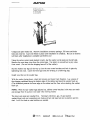
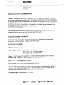
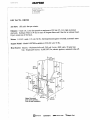
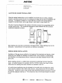
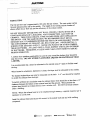
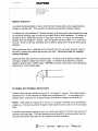
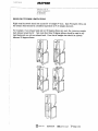
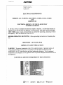
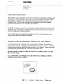
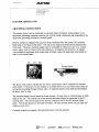
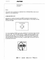
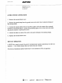
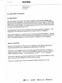
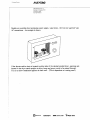
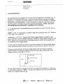
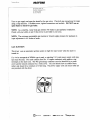
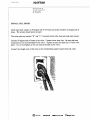
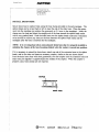
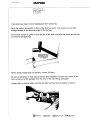
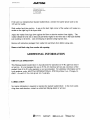
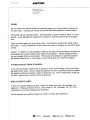
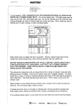
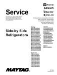
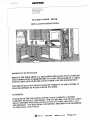
240EdwardsStreet,$E
Cievelaeg,Tennessee373;;
TeL:423-472-3333
Fax:423-478-6710
STACKED WASHER- DRYER
INSTALLATION INSTRUCTIONS
IMPORTANT TO INSTALLER
REMOVE THE DOOR FROM ALL DISCARDED APPLIANCES SUCH AS DRYERS
AND COMBINATION WASHER/DRYERS TO AVOID THE DANGER OF A CHILD
SUFFOCATING SHOULD HE/SHE CRAWL INSIDE AND THE DOOR BE SHUT.
THE DRYER MUST NOT BE INSTALLED OR STORED IN AN AREA WHERE IT
WILL BE EXPOSED TO WATER AND/OR WEATHER.
US MODELS
PLEASE READ THE FOLLOWING INSTRUCTIONS CAREFIJLLY BEFORE
STARTING TO INSTALL THE DRYER. FOR GAS DRYERS, THE INSTALLATION
MUST CONFORM WITH THE NATIONAL FUEL GAS CODE ANSI Z223.1, LATEST REVISION. ANY QUESTIONS CONCERNING THIS SHOULD BE REFERRED
TO THE LOCAL GAS UTILITY.
C_sto_er
Se_i_e
__
240 EdwardsStreet,SE
Cleveiand,Tennessee3731l
Tel:423-472-3333
Fax:423-478-6710
IMPORTANT TO OWNER
Retain these instructions for future reference.
This new Maytag appliance is designed to serve you dependably for many years. However,
it cannot do so unless provided with sufficient electrical power, suitable exhausting and if a
gas model, adequate gas supply. We urge you to read this carefully to make sure all
requirements are met.
Operating instructions, safety precautions and your warranty are in the accessory package
with each appliance. Read the operating instructions carefully.
NOTE: A wiring diagram for the dryer is located on the inside of the dryer access panel. A
wiring diagram for the washer is located on the inside of the washer front panel.
UNCRATING
To remove carton, cut around bottom of carton on or below dotted line. Cut down each
corner of carton (vertically) and "peel" carton away from stacked washer/dryer. Fold carton
material for removal. Check the unit for shipping damage.
The control cable for the washer is taped to the rear of the dryer stand at the bottom.
Remove tape from control cable and temporarily place end of control cable in dryer vent.
From the back of the Stacked Washer/Dryer, grasp the dryer and stand. Pull dryer and stand
back and off of washer and shipping base. As dryer and stand are pulled back, carefully drop
dryer stand rear legs to the floor before clearing shipping base. (Do not drop dryer and stand
off of shipping base!).
CustomerSe,_Jice
A4__
2a(] EdwardsStreet.SE
Cleveland,Tennessee37311
Tel:423-472-3333
Fax:423-478-6718
Untape and open washer lid. Remove installation accessory package, fill hoses and drain
hose and close lid. Leave tub block in place until installation is complete. Be sure to remove
tub block after installation is complete and before use. !
Using the carton corner posts stacked in pairs, lay the washer on the posts on the left side.
Remove the crate base wires from the carton base. Use pliers or screwdriver to pry wires
from wood. (Do not kick the shipping base off of the washer).
Run the washer rear legs all the way up into the rear corner brackets and lock in place by
tightening lock nuts. Leave the front legs loose for leveling in a following step.
Install vinyl feet on the washer legs.
With the washer laying down, check belt tension and motor track freedom. Lay a piece of
the shipping cardboard along the bottom edge of the cabinet and stand the washer back up.
(The cardboard protects the lower edge at the cabinet and the floor when standing the washer
back up).
NOTE: With the rear washer legs adjusted up, cabinet corner brackets in the rear can touch
and damage floor if caution is not used when moving washer
The dryer and stand are installed first. Necessary electrical, gas, (if gas stacked
washer/dryer) and vent connections are made as dryer and stand are put in position and leveled. Let's first look at what facilities are needed.
2a-O
EdwardsStreet.SE
Cleveland,Tennessee
3731i
Tei:423-4723352,
Fax:_.23-478-6710
PREINSTALLATION CONSIDERATIONS
Location: The stacked washer/dryer is approved for zero clearance installation on the sides
and the back (depending on venting used). The location selected must take into consideration
the dimensions of the unit and convenience for customer use and access in case service should
be needed. The floor must be capable at supporting the weight of the unit (approximately
340 pounds) plus water (approximately 130 pounds) and be stable enough to prevent excessive vibration in spin cycles. A floor which is adequate for the standard washer is sufficient
for the stacked washer/dryer.
The following specifications and drawings show dimensions and locations of fill valve, terminal block (electric dryer) gas inlet (gas dryer) and drain outlet.
STACKED WASHER AND DRYER
Basic Dimensions 27 1/2" W x 27 1/2" D x 73" H (min). See drawings for complete
dimensions. Uncrated Weight: Approximately 340 pounds.
KEY FACTS - WASHER
Capacity: Standard (16 gallons)
Water Usage: (full cycle) - 36 (30 Imp.) gal: 136 liters - large
30 (25 Imp.) gal: 114 liters - medium
24 (20 Imp.) gal." 91 liters - small
Motor: 1/2 H.E rated; 115 volt; 60 Hz; reversible; thermoprotected against overload;
automatic reset. Model LDE7804 available in 220-240 volt; to Hz.
Power: O. 1 - O.17 kwh depending on cycle.
Hose Lengths:
Inlet 5 feet (1.52 m); drain 4 feet (I.22 m).
Installation Requirements: Hot and cold water connections with water pressure within 30120 p.s.i. (2.11-8.44 kg/cm) range; 120F to 140F hot water; a drain; a 120 volt, 60Hz
electrical outlet properly grounded and protected by a 15 amp fuse.
Uncrated Weight:
Approximately 340 pounds.
_"_ MA'_r._.C
.ldm|rai
_1
"_w'i" J E N N -,,_II=I
_MilcJi¢
C ,"'le|
240Edwards
Street.SE
Cieve!and,
Tenpessee
373T
Tel:423-472-3333
Fax:423--t78-6710
KEY FACTS - DRYER
Air Flow: 180 cubic feet per minute.
Exhaust: 4 inch (10.2 cm) duct pe_-,_itsa maximum of 50 feet (15.4 m) rigid aluminum
ductwork. Subtract 8 feet (2.44 m) for each 90 degree elbow and 8 feet for an exhaust hood.
Dryer vented out of the back.
Motor:
1/4 H.P. rated; 115 volt; 60 Hz; thermoprotected against overload; automatic reset.
Export Model - Model LDE7804 available in 220-240 volt; 50 Hz.
Heat Source: Electric - Nichrome helix coil, 240 volt 3-wire, 4600 watts, 30 amp fuse.
Gas - Single port burner; l 8,000 BTU/hr; electric ignition; automatic shut-off.
13W'
cm
Note: Recessed
69.9 cm ._.
back panelpermits
flush-to-wall installation.
[]
MAYI'AG
271/£
69.9cm
Admiral 7J
_,OENN.,aa_
"_'__9_
¢,Nef
C stom r
,hCI,
AY'J I G
240Edwards
Street.SE
C!eveland,
TenPessee
3731;
Tei:423-472-32,33
Fax:423-478-67!
0
ALCOVE OR CLOSET INSTALLATION
When the stacked washer/dryer is to be installed in an alcove area or a closet, clearance
should be provided around the unit for an adequate air supply and for ease of installation and
servicing. An appliance installed in a closet shall have no other fuel burning appliance
installed in the same closet, such as gas furnace, water heater or space heater, etc.
The dryer must be exhausted to the outside to minimize excessive lint accumulation and to
maintain good drying. We recommend allowance for more clearance than the minimum
installation clearances as shown.
Ceiling
./'
I.
_L c,o,.,
oo.
,It
::
\'\
\
BI
sq. t
O_nin!
_
..
\
0"
-
[
, I, 0"
/
i a"
t
,J
FRONTVIEW
,
--_.1/2"
r"
SlOE
VIEW
_'
Each openingareamusthavea minimum of 36 squareinches. Theseopeningsmustnotbe
obstructed. (Louvereddoor with equivalentair openingis acceptable).
MOBILE HOME INSTALLATION
Installation of Maytag dryers certified by the American Gas Association and bearing a label
stating they are suitable for installation in mobile homes, when installed in mobile homes,
must conform to the Manufactured Home Construction and Safety Standard Title 24 CFR,
part 32-80.
When installing a dryer in a mobile home, provisions for anchoring the dryer should be
made. An anchor bracket kit is available, Part No. 303740 to fasten dryer stand to floor.
Instructions for installing the anchor brackets are contained in each kit.
All mobile home installations must be exhausted to the outside with the exhaust duct termination securely fastened to the mobile home structure, using materials that will not support
combustion. Exhaust the dryer using flexible metal exhausting materials and locate in an area
that provides adequate make-up air. The exhaust duct may not terminate beneath the mobile
home.
240EdwardsStre_:,SE
C_evefand.
Tennessee_731T
Tel:422-472-,7,33S
Fax:423-478-67_3
MAKE - UP AIR
For proper operation of the dryer unit, it is important to make sure the location has adequate
make-up air. This is especially important in any confined area such as a bathroom or closet.
There must be at least two 36 inch square unobstructed openings for intake air. This can be a
louvered door or other equivalent opening.
On gas dryer units in particular, adequate clearance as noted on the dryer minimum clearance
label should be maintained to insure enough air for combustion and proper operation of the
dryer. The area where located must not obstruct the flow of combustion or ventilating air.
When installing a Maytag Stacked Washer/Dryer the following minimum clearances to combustible surfaces must be maintained; clearance to wall and sides, 0 inches, top, 6 inches,
front I/2 inch to washer, rear 0 inches with an outside exhaust, 4 inches with an inside
exhaust (not recommended). See Exhausting Section and Installation Accessories for exhaust
kits.
SERVICE ACCESS
Location should allow access to the foot at the unit for washer and dryer service. Access
must be available to two screws at the top front corners of the dryer front panel (on the top).
240Edwards
S:r,_e':,
SE
C!eveland,
Tenressee
27SI
i
Tel:42_-472-2223
Fax:_.23-478-67"
0
EXHAUSTING
The free air flow rate is approximately 180 cubic feet per minute. The vent system carries
lint and moisture away and to the outside. The length of the venting and the number of
elbows affect the air flow rate and the efficiency of the exhaust system.
DO NOT EXHAUST DRYER INTO ANY WALL, CEILING, CRAWL SPACE OR A
CONCEALED SPACE OF A BUILDING, VENT CONNECTION, GAS VENT OR
CHIMNEY. THIS COULD CREATE A FIRE HAZARD FROM LINT EXPELLED BY
THE DRYER. FOR THE SAME REASON, WE RECOMMEND ONLY METAL
EXHAUST DUCT TO MINIMIZE RESTRICTED AIR FLOW AND RELIABLY INSURE
THE CONTAINMENT OF EXHAUST AIR, HEAT AND LINT. NEVER INSTALL A
SCREEN OVER EXHAUST OUTLET. NEVER USE PLASTIC OR OTHER COMBUSTIBLE DUCTWORK. AT LEAST ONCE A YEAR, INSPECT AND CLEAN INTERIOR
OF DUCTWORK, FREQUENTLY CHECK AND CLEAN VENT HOOD TO ASSURE
PROPER OPERATION.
A clothes dryer produces combustible lint and the area around the clothes dryer should be
kept free of lint. DO NOT STORE FLAMMABLE LIQUIDS OR MATERIALS NEAR
A DRYER.
It is recommended that a dryer be exhausted to the outside using 4" rigid or flexible metal
ducting.
When located in a bedroom, bathroom or closet, the dryer must be exhausted to the outside.
The stacked washer/dryer can only be exhausted out the back. A 4" vent should be installed
to accept the exhaust from the dryer.
To permit sufficient air circulation under the exhaust hood, there should be no less than a 12"
clearance between the bottom of the exhaust hood and the ground. When possible the
exhaust hood should not exhaust directly into a window well. DO NOT terminate exhaust
under a building.
NOTE: Where the exhaust hood is to be installed through masonry, a special masonry saw is
necessary to cut the hole.
Install the exhaust hood and secure with screws to the outside wall and seal with caulking
compound.
[]
MA'_TAG
Adf'_]l'a|
7]
ZI_-JENN-A_I:I
_"_ie
<:he[
2_0 EdwardsStreet SE
Cieveiand.Tennessee
87311
Tel:422-472-3333
Fax:_22-4786710
DIRECT EXHAUST
An exhaust hood positioned to line up with the dryer exhaust pipe can be installed directly
through an outside wall. This would be the shortest and most direct exhaust method.
To exhaust up, route standard 4" diameter ducting up the recess and in the cabinet back using
the furnished retaining strap an screws to get nearly flush to wall installation. To exhaust to
the side or down, install the furnished 4" long duct with four "S" clips to the inner dryer
exhaust, then use standard 4" ducting. This will position the dryer about 4 1/2" away from
the wall. Flush to wall side exhausting may be done by going above the dryer before going
sideways.
When exhausting down, wallboard can be removed from the wall to get the dryer closer to
the wall by placing the exhaust pipe between the studs. Check local codes for required
exhaust clearances.
Install ductwork from the dryer to exhaust hood. All joints must be made so exhaust end of
one pipe is inside the intake end of the next pipe. On flexible metal ductwork, all joints
should be secured with a 304630 clamp. DO NOT use sheet metal screws when assembling
rigid ducting. Joints should taped.
Ill
FLEXIBLE DUCTWORK LIMITATIONS
Flexible metal ductwork should not exceed 34' of straight 4" ducting. The exhaust hood is
equivalent to 8' of duct and each 90 degree bend is equivalent to 8'. As an example if an
exhaust hood is used and two 90 degree bends, the maximum straight run would be 10'.
NOTE: If the radius of a bend with 4" duct is 12" or greater, the bend can be considered a
straight run. No more than three 90 degree bends should be used in any run with an exhaust
hood.
If flexible metal exhaust ducting is used, cut a short piece (about 3") off the male end of a 4"
diameter metal duct pipe. The short extension can be secured to the dryer exhaust with the
clips and the flexible metal duct can be clamped to the short extension.
MA_TAG
Adm_r:al
_!
[d/NN-AJPl
"_'}llla_Jk_ C_et
C tamerSe ie0
hl,4
240Edwards
Street,SE
Cleve4and,
Tennessee
,37311
Tel:423-472-3333
Fax:423-,i78-8710
RIGID DUCTWORK LIMITATIONS
Rigid metal ductwork should not exceed 50' of straight 4" duct. Each 90 degree elbow and
the exhaust hood should be considered equivalent to 8' of straight ductwork.
For example, if an exhaust hood and two 90 degree elbows are used, the maximum straight
duct allowed would be 26'. Not more than three 90 degree elbows should be used in any
rigid ductwork run with an exhaust hood. Four feet of straight duct should be allowed
between 90 degree elbows
C st0mer 0 ice
hllA
240Edwards
Street,SE
Cleveland,
Tennessee
37311
Tel:423-472-$333
Fax:423-478-'3710
ELECTRICAL REQUIREMENTS
OBSERVE ALL NATIONAL ELECTRICAL CODES, LOCAL CODES
AND
ORDINANCES
ELECTRICAL SERVICE - 120 VOLTS, 60 HZ ONLY
WASHER-GAS DRYER
A 120 volt, 60 Hz, 15 ampere fused electrical supply is required. An individual branch (or
separate) circuit serving only this appliance is recommended. DO NOT USE AN EXTENSION CORD unless it meets all requirements as outlined for grounding, polarizing (3-wire)
and capacity. Wire size should be at least No.14.
BEFORE OPERATING OR TESTING,
tion.
follow grounding instructions in Grounding Sec-
GROUNDING - 120 VOLTS, 60 HZ
IMPORTANT SAFETY PRECAUTIONS
WARNING - To prevent unnecessary risk of fire, electrical shock or personal injury, all
wiring and grounding must be done in accordance with the National Electrical Code
ANSI/NFPA, No.70, Latest Revision and local codes and ordinances. It is the personal
responsibility and obligation of the appliance owner to provide adequate electrical service for
this appliance.
ELECTRICAL GROUND IS REQUIRED ON THIS APPLIANCE
J_
MA'I .rAG
.ldrr_i'al
lJ
-'_'_'_JE_N.Ai_
9j't,l_gi¢
C_',ef
CustomerSer,,'ica
.i_j_"_l_
240EdwarosStreet.SE
C'_eve]and,
Tennessee373!1
Tek423-472-3333
Fax:423J-78-67;0
GROUNDING INSTRUCTIONS
This appliance must be grounded. In the event of malfunction or breakdown, grounding will
reduce the risk of electric shock by providing a path of least resistance for electric current.
This appliance is equipped with a cord having an equipment-grounding conductor and a
grounding plug. The plug must be plugged into an appropriate outlet that is properly
grounded in accordance with all local codes and ordinances.
DANGER - Improper connection of the equipment-grounding conductor can result in a risk
of electric shock. Check with a qualified electrician or serviceman if you are in doubt as to
whether the appliance is properly grounded.
Do not modify the plug provided with the appliance. If it will not fit the outlet, have a
proper outlet installed by a qualified electrician
ADDITIONAL GROUND PROCEDURE - WHERE LOCAL CODE PERMITS.
An external ground wire, clamp and screws are provided for assistance in meeting local
codes. Where approved, it is recommended this additional ground be installed. A suitable
external ground connection MUST be determined prior to wire hookup. Consult local building officials and qualified electrician in the event any questions exist.
NEVER CONNECT GROUND WIRE TO PLASTIC PLUMBING LINES, GAS OR
HOT WATER PIPES.
ALL GROUNDING AND WIRING MUST BE DONE IN ACCORDANCE WITH
NATIONAL AND LOCAL CODES.
i
V_,_XYrAG
Admira| _1
_
JE_N-AJR
_-_la_icChef
240EdwardsStreet.SE
Cleveland,Tennessee37311
Tel:423-472-3333
Fax:423-478-6710
ELECTRIC DRYER UNITS
GROUNDING INSTRUCTIONS
This electric dryer must be connected to a ground metal, permanent wiring system; or an
equipment grounding conductor must be run with the circuit conductors and connected to the
equipment grounding terminal on the back panel.
Electric models are shipped with a ground strap connected from the neutral (P2) terminal
block post to the frame of the dryer. The use of this strap is permitted by the national electrical code. The dryer electrical supply may be connected by means of a new U.L. Listed
power supply cord kit rated at 240 volts minimum, 30 amperes with three No. 10 copper
wire conductors terminated with closed loop terminals, open end spade lugs with turned up
ends or with tinned leads.
P-l P2 '-Ps
The power cord must be marked for use with a clothes dryer and be retained with suitable
strain relief. If the dryer is to be installed in a mobile home or an area where local codes do
not permit grounding through neutral, only a 4 conductor power cord, rated and terminated
as above, may be used.
The electrical supply circuit should be fused through a 30 amp fuse or circuit breaker on both
sides of the line. The neutral line of the service cord must always be connected to the P2
terminal post. The two hot lines of the service cord go to the P1 and P3 terminal block
posts. The neutral should not be fused or broken. Be sure terminal block nuts are tight and
replace access cover.
Canadian models are shipped with approved power cord sets attached.
[]
MA'_FAG
Admiral 71
,_'_,_E_N-,_r_
"_gaeji¢
Chet
Customer
Se_i_a
__
240EdwardsStreet,SE
C[eveiand.Tennessee37311
Tel:423-472-3333
Fax:423-478-6710
G.F.I.
If the electric dryer is protected by a GROUND FAULT INTERRUPTER, follow the procedure for a 4-wire hookup below.
4-WIRE RECEPTACLE
The frame of a 120/240 Volt machine must NOT be connected to neutral terminals. It
MUST be connected to the 4th wire (green of the power supply) or to the metallic covering
of a three-wire supply.
Four Wh'l ReCeplacle
If a 4-wire receptacle of NEMA type is used, a matching UL Listed power supply cord (pigtail) must be used. This cord contains four NO. 10 copper conductors with spade or ring
terminals on the dryer end. The 4th (grounding) conductor must be identified by a green
cover and the neutral conductor by a white cover. The cord should have a suitable strain
relief and should be a minimum of 4 feet long. The poser supply cord and strain relief are
not provided with the dryer.
MA_TAG
Admiral
_J
:'mnmJENN-A.II::I
_'J)L3cJi¢
C:"_ef
240Edwards
Street.SE
Clevebnd,
l_nne.<_ee
37311
Tel:423-472-3S:3
Fax:423-478-67"
0
4-WIRE SYSTEM CONNECTIONS
1. Remove the terminal block cover.
2. Remove the ground strap from the ground screw and center (silver colored) terminal of
the terminal block.
3. Connect the neutral (white) wire of the power supply cord to the center (silver colored)
terminal of the terminal block. Connect the grounding (green) wire of the cord to the external ground connector, sing the green screw.
4. connect the other two wires of the cord to the outer terminals of the terminal block.
5. Replace the terminal block cover.
208 VOLT OPERATION
A 306378 kit is used to convert the electric microprocessor stacked washer/dryer for 208 volt
operation. A new heater element label and instructions are included.
The elctrical mechanical stacked washer/dryer is not available for 208 volt operation.
['_ MA'_r.\G
Admiral rl
_._,J_NN-A_
"_agi¢
ehet
C_s:cme,
Se_,ice
__
240 EdwardsS[ree[.SE
Cleveiand,Tennessee2,7311
Tel:423472-3333
Fax:423-478-6710
WATER SUPPLY AND DRAIN
WATER SUPPLY
The water supply to the washer unit should be capable of providing both adequate water
pressure and water temperature. The pressure should fail within the range of 30 pounds per
square inch to 120 pounds per square inch when the washer is filling. Note that this is flow
pressure and not static pressure. Low water pressure will result in slow fill and could result
in a water valve sticking open after a fill.
The temperature of the hot water as delivered to the washer should be 140 degrees F. The
temperature of the cold water as delivered to the washer should be 75 degrees F.
Warm water temperature is a result of the mix of the hot and cold water supplies. The final
temperature is dependent on both the pressure and the temperatures of the hot and cold supplies. The desired temperature for warm is between 100 degrees F and 105 degrees F.
DRAIN FACILITIES
Because of the desirability of flush to the wall installation of the stacked washer/dryer, a
drain directly behind the unit is preferred to a drain located on either side,
The washer unit is equipped with a built-in siphon break which allows for a variance in
height of the drain facility. The drain must be capable of accepting a flow rate of approximately 20 gallons per minute. An inside diameter of at least 1" - 1 l/2" is required.
The portion of the drain hose from the siphon break to the drain can be extended to a floor
drain. Consult the parts catalog for extra drain hose as needed.
The use of a laundry built-in wail box can greatly simplify installation of the unit.
.'vlA'_rA6
Admiral
_|
_'L_
j ENN
.g_l]l:l
_-_'!bllagiC 'C}'_e|
C_0mer
Se_isa
__
240EdwardsStreet,SE
C!eveiand,Tennessee27311
Tel:423-472-3333
Fax:423-478-6710
Models are available that incorporate water supply, water drain, 120 Volt AC and 240 Volt
AC connections. An example is shown.
O
3
©
If the faucets and/or drain is located to either side of the stacked washer/dryer, openings are
located in the dryer stand uprights to allow hoses and power cords to be passed through.
This is to allow installation against the back wall. (This is dependent on venting used.)
_[_"_,VIA'fl-AG Adm|raiT|
m,JENN-AJR
"J_'_ic
Chef
Cus 0merSe ic
,/i gtlG
240EdwardsStreet,SE
C1eveiand,
Tennessee37311
Tel:423-472-3333
Fax:_23-478-67:0
GAS CONNECTION
Gas operated dryers are equipped with a burner orifice for operation on NATURAL gas. If
the dryer is to be operated on LP gas, it must be converted correctly for safety and proper
performance. Conversion kits from NATURAL to LPG or LPG to NATURAL are available
through your local Maytag dealer. If other conversions are required, check with local gas
utility for specific information concerning conversion requirements. NOTE: The conversion should always be performed by a qualified service technician.
A 1/2" gas supply line is recommended and must be reduced to connect to the 3/8" gas line
on the dryer.
NOTE: A 3/8" x 2" pipe nipple is included to adapt valve connection from a 3/8" female to
a 3/8" male I.P.S. connection.
Additionally, a 1/8" N.P.T. (National Pipe Thread) plugged tapping, accessible for test
gauge connection, must be installed immediately upstream of the gas supply connection to the
dryer. Refer to your local gas utility or plumbing contractor should you have questions on
the installation of the plugged tapping.
The dryer and its individual shut-off valve must be disconnected from the gas supply piping
system during any pressure testing of the system at test pressures in excess of 1/2 P.S.I.G.
The dryer must be isolated from the gas supply piping system by closing its individual
manual shut-off valve during any pressure testing of the gas supply piping system at test
pressures equal to or less than 1/2 P.S.I.G.
.,_- Gas
Line
1/8" NPT
Dryer
/_
-Gas
Plug
Line
The gas supply should be connected to the dryer using pipe joint compound or a Teflon tape
on male thread connections. NOTE: Any pipe joint compound used must be resistant to the
action of any liquefied petroleum gas.
MA_[AG
Admiral
7|
_n_-JE_IN-AJR
x_llacJi¢
¢_ef
240Eswards
Street,SE
Cbve4and,
Tennessee
37311
Tel:423-472-3333
Fax:£23-478-8710
Turn on gas supply and open the shutoff at the gas valve. Check all gas connections for leaks
using a soap solution. If bubbles occur, tighten connections and recheck. DO NOT use an
open flame to cheek for gas leaks.
NOTE: As a courtesy, many local gas utilities will inspect a gas appliance installation.
Check with your utility to see if this service is provided in your area.
NOTE: The minimum permissible gas (natural or mixed) supply pressure for purposes in
input adjustment is 4.5 inches of water.
GAS IGNITION
This dryer uses an automatic ignition system to light the main burner when the dryer is
turned on.
If a 4-wire receptacle of NEMA type is used, a matching UL Listed power supply cord (pigtail) must be used. This cord contains four No. 10 copper conductors with spade or ring
terminals on the dryer end. The 4th (grounding) conductor must be identified by a green
cover and the neutral conductor by a white cover. The cord should have a suitable strain
relief, and should be a minimum of 4 feet long. The power supply cord and strain relief are
not provided with the dryer.
Cus 0me
S0r,
240 EdwardsStreet,SE
Cleveland,Tennessee37311
Tel:423-472-3333
Fax:423-478-6710
INSTALLATION
INSTALL DRYER UNIT AND STAND
The dryer and stand are installed first. With the connections prepared for exhausting, electric
power and gas (if gas stacked washer/dryer, see Gas Connection), the dryer and stand are
moved to the location.
NOTE: When moving the dryer and stand on an appliance hand truck, it is recommended
that the dryer and stand be trucked upside down. Protective padding should be used to avoid
damage to the cabinet finish.
Install the vinyl feet on the dryer stand legs. Note the rear legs are "washer" legs and use
the larger feet.
Install electric power cord (electric stacked washer/dryer).
tion.
See Electrical Requirements sec-
The vent connection is lined up from underneath the dryer as the dryer and stand are moved
back into position when a straight-out-the-back vent is used. When venting down, up, or to
the side, an elbow or fiat duct section is placed on to the dryer exhaust before the dryer is
slid into position.
Level the dryer and stand and lock leveling legs using leg lock nuts.
Connect gas line for gas units and check for leaks. Use a liquid soap solution or leak detector. DO NOT use a match or open flame !
With dryer "andstand in position, exhaust vent connected, unit leveled and gas line connected
(if gas unit), power cord set installed (if electric unit), plug power cord into electric outlet.
INSTALL WASHER UNIT
Install washer glide bars on rear of washer cabinet. The glide bars are in the installation
package found in the washer tub. Install with rounded edge down. The glide bars will
extend beyond the edge of the cabinet on each side when properly installed.
[]
MA_/I'AG
Admiral
_J
m
JENN1.A]I:I
_"i_lgi¢:
C,_le[
CusiemerService
,,,l__
240 EdwardsStreet, SE
C]eve/and,Tennessee37311
Tel:423-472-3333
Fax:_23-478-6710
INSTALL FILL HOSES
Insert plain hose washers in 90 degree end of fill hoses and screen washers in straight end of
hoses. The screens should point outward.
The valve inlets are marked "H" and "C" to denote the hot inlet (top) and cold inlet (lower).
Connect 90 degree ends of hoses to the valve. Connect lower hose first. Be sure that hose
connectors are not cross threaded on the valve. Tighten securely by hand plus 1/4 turn with
pliers. Do no overtighten as this can strip the threads on the valve.
Connect the straight ends of the hose to the corresponding supply faucets (hot and cold).
_]
MA_rA6
Admiral
[J
mJENN-AIR
"_'Ma(jJ¢
Chef
240Edwards
Street,SE
Cleveland,
Tennessee
37311
Tel:423-472-3333
Fax:423-478-6710
INSTALL DRAIN HOSE
Secure drain hose to siphon break using the hose clamp provided in the parts package. The
siphon break can be turned right or left to meet the end of the drain hose. Place the gooseneck into the standpipe (or position the gooseneck as if it were in the standpipe). Insert the
clamp over the hose and direct the straight end of the hose toward the siphon break outlet
with a very gradual bend. Push the drain hose over the siphon break outlet and if necessary
twist the hose to relieve any stress on the hose between the siphon break outlet and the
standpipe after the hose is inserted into the standpipe.
NOTE: It is very important when connecting the drain hose that # is properly installed to
minimize the chance of the hose becoming ldnked when the washer is moved into position.
If it is necessary to extend the drain hose, attach one end of the extension hose to the siphon
break, and in the other end insert an accessory coupler, similar to the one shown below.
Push the drain hose (hose with short gooseneck) over the coupler until the extension hose and
drain hose join together in approximately the middle of the coupler. When the coupler is
properly used, hose clamps are not required.
¢OUPUl
DILAIN HOSE
[]
MAYrAG
Aarniral
_J
-"m_dENN-AJP
_'_agi¢
C."lef
Cu_0mer
Sa_'ica
_t[A]Ip]_
240EdwardsStreet,SE
C!eveiand,Tennessee37311
Te_:423-472-3333
Fax:423-478-6710
If not previously done, remove shipping pads from washer top.
Move the washer into position in front of the dryer and stand. Use caution to avoid floor
damage because of the minimum height of the rear legs.
Tip forward enough for glides to clear the legs of the stand, and guide the glides into the slots
on the top of the stand legs.
Lower Washer Glide
Bar Down into slot.
Slide Washer Back
onto Stand
/
Before sliding washer back into position, connect fill hoses.
Be sure the gooseneck is fully inserted into the drain standpipe to prevent any chance of the
hose coming out of the standpipe from the force of the water being discharged.
Connect the-two control cables, one from the dryer and one from the washer, as shown.
[]
MA_r, XG
Admiral
7l
:Ua_JENN-,X_R
"_laqic
C.._et
Caste_er
Se,_,in_
a_jLA _
240 EdwardsStreet,SE
Cleveland,Tennessee3731
Tel:423-472-3333
Fax:423-478-6710
If the unit is a microprocessor stacked washer/dryer, connect the washer power cord to the
120 volt AC outlet.
Slide washer back into position. A peg on the back right corner of the washer will locate in a
socket on the right leg of the dryer stand.
Adjust the washer front legs down against the floor to raise the washer front slightly. The
washer should be level side to side and just barely higher in the front than in the back (bubble
just touching in the level). Lock leveling leg in position using leg lock nuts.
Remove all instruction packages from washer tub and dryer drum before using units.
Remove tub block ring from washer tub opening.
ADDITIONAL INFORMATION
ODD CYCLE OPERATION
This Maytag stacked washer/dryer is manufactured for operation on 60 Hz approved electrical service. It is not designed for use on 50 Hz AC electrical service and conversion of the
product from 60 to 50 cycle operation is not recommended. For additional information on 50
cycle products, write, MAYTAG INTERNATIONAL, 8700 Bryn Mawr Ave. Chicago, IL
60631. Or call 312-714-0100 (FAX 312-714-8180).
LUBRICATION
No routine lubrication is required to maintain the stacked washer/dryer. In the event something does need attention, contact an authorized Maytag dealer or servicer.
MA_I'AG
Aamira|
7]
_
JENN-A_I::I
_lla_l_::
C_ef
240Edwards
Street.SE
C_eveland,
Tennessee
373!1
TeL:¢23-472-3333
Fax:423-478-6710
FINISH
All the cabinet and external finishes are protected against rust to keep product looking well
for many years. Cleaning and waxing will provide additional protection to these finishes.
The washer top has a porcelain finish. Since porcelain is *glass" bonded to metal, it is very
durable. Avoid damage from sharp blows of objects or tools used around and in the appliance.
Clean the control panel with a soft damp cloth. Avoid abrasive cleaners that would scratch
the surface. A coat of household was will reduce the chance of scratches on the control panel
surface.
Caution: If "spilled" or used improperly, bleaches and other strong laundering chemicals can
permanently spot or stain finishes unless wiped up immediately. Aerosol pretreat products
can also damage finish on control panel. When using these products on garments placed in
the stacked washer/dryer, it is advisable to avoid control panel area with the overspray.
WATER DAMAGE FROM FLOODING
In the event the stacked washer/dryer is exposed to water from flooding, call you local Maytag dealer before using. Always unplug the appliance and have a qualified technician inspect
the appliance before any attempt is made to operate the unit. Never wash product inside and
out with a garden hose or pressure cleaning equipment.
REPLACEMENT PARTS
If your unit requires replacement parts, contact the dealer from who you purchased your
appliance, or Maytag Customer Service, 240 Edwards St. SE, Cleveland, TN 37311 for
information on the nearest Maytag parts distributor.
Service manuals are available through your dealer or nearest parts distributor.
k_
MAYfAG
Admiral
71
....... J_NN-_
_l._q_
e,hef
Customer
Servi_e
,,ll_l_,_r_
240Edwards
Street,SE
Cleveland,
Tennessee
37311
Tel:423-472-3333
Fax:423-478-67;
0
INSTALLATION ACCESSORIES
059129
Vent hood - 4" (10.16 cm) opening
059130
Aluminum pipe - 4" x 24:(10.16 cm x 60.96 cm)
059131
Aluminum elbow - 4" (10,16 era)
059134
Aluminum window plate - 15" x 20" (38.10 cmx 50.80 cm) - 4"
(10.16 cm) hole
059143
Flexible vent kit - contains wide opening vent hood, wall plate, two
clamps and flexible aluminum vent duct
304353
Flexible aluminum vent duct - 4" (I0,16 cm) diameter 38" (81.28 era)
length stretches to 8' (2.44 m)
304630
Clamp for flexible aluminum duct.
306642
Exhaust deflector kit - inside exhaust kit
306205
Natural to LPG conversion it for gas valve
311353
Dacron lint bag
[]
,MA"ffA6
Admiral
_',1
_.a._,.:E_N.,_
_Alagi¢
Chef