1
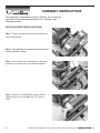
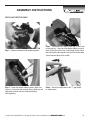
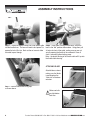
OPERATIONS MANUAL
AND PARTS BOOK
EDI-13261 PART# SW100H
Marshalltown, IA
Phone 800-888-0127 / 641-753-0127
Fax 800-477-6341 / 641-753-6341
www.marshalltown.com
WS570
TABLE OF CONTENTS
Common Components . . . . . . . . . . . . . . . . . . . . . . . . . . . . . . . . . . . . . . . . . . 3
Assembly Instructions . . . . . . . . . . . . . . . . . . . . . . . . . . . . . . . . . . . . . . . . . . 4-6
Machine Adjustments . . . . . . . . . . . . . . . . . . . . . . . . . . . . . . . . . . . . . . . . . . . 7
Parts Breakdown . . . . . . . . . . . . . . . . . . . . . . . . . . . . . . . . . . . . . . . . . . . . . . 8-9
Wet Screeding . . . . . . . . . . . . . . . . . . . . . . . . . . . . . . . . . . . . . . . . . . . . . . . . 10
Form to Form Screeding . . . . . . . . . . . . . . . . . . . . . . . . . . . . . . . . . . . . . . . . 11
Technical Data/Capacities . . . . . . . . . . . . . . . . . . . . . . . . . . . . . . . . . . . . . . . 12
Maintenance Schedule . . . . . . . . . . . . . . . . . . . . . . . . . . . . . . . . . . . . . . . . . 12
How to Operate . . . . . . . . . . . . . . . . . . . . . . . . . . . . . . . . . . . . . . . . . . . . . 13-14
Warranty . . . . . . . . . . . . . . . . . . . . . . . . . . . . . . . . . . . . . . . . . . . . . . . . . . . . 15
This machine was built with user safety in mind, however, it can present hazards if improperly operated and serviced. Follow
operating instructions carefully and use good judgement when operating!
If you have questions about operating or servicing this equipment, please contact your Marshalltown distributor or Marshalltown
Company at 800-888-0127 or 641-753-0127.
2
To order: Phone: 800-888-0127 • Fax: 800-477-6341 • Visit our Website at www.marshalltown.com
COMMON COMPONENTS
1. Start/Stop Switch
2. Engine
3. Recoil Starter
4. Oil Cap
5. Gas Cap
6. Throttle Lever
7. Handle Bar Mounting Blocks
8. Handle Bars
9. Adjustable Hand Grips
10.Kickstand
6
11.Drive Shaft
12.Vibration Dampeners
13.Blade
14.Eccentric Weight Cover
15.Frame
16.Lifting Bar
19
17.Tachometer/Hour Meter
18.Board Mounting Plate
19.Throttle Cable
20.Air Filter
9
16
8
3
5
4
20
2
10
1
The Premier Line
17
15
18
11
7
12
14
12
13
To order: Phone: 800-888-0127 • Fax: 800-477-6341 • Visit our Website at www.marshalltown.com
3
ASSEMBLY INSTRUCTIONS
Your Shockwave™ Screed power unit ships in two boxes, one containing the
handle bars and the other containing the power unit. Assembly is easy,
following these steps:
INSTALLING HANDLE BARS AND KICKSTAND:
Step 1 – Remove the 4 hex screws (A) that hold down the two
handle mounting blocks.
A
Step 2 – Slide kickstand arm onto kickstand end and fasten
with nut & bolt (B) as shown
B
Step 3 – Place handle bars into mounting blocks, making sure
handle bars are centered evenly across the mounting blocks.
Step 4 – Making sure all mounting block and frame holes are
aligned, insert hex screws and tighten with 7/16" wrench or
socket.
4
To order: Phone: 800-888-0127 • Fax: 800-477-6341 • Visit our Website at www.marshalltown.com
ASSEMBLY INSTRUCTIONS
INSTALLING THROTTLE CABLE:
B
A
Step 1 – Remove carburetor cover by pressing clips.
Step 3 – Fasten the throttle cable as shown. Make sure
there is a nut on each side of plastic fitting. Made sure the
cable does not work itself out of the plastic fitting
while tightening.
Step 2 – The throttle has a rotating silver peg (A) with a slot
on one side of it. One end of the throttle cable has a metal
barrel (B) that fits into this slot. Insert barrel into the slot so
when the throttle cable is pulled, it will pull the throttle open
(toward the base plate of the screed).
Step 4 – Attach the throttle lever to the “T” grip handle,
as shown above.
To order: Phone: 800-888-0127 • Fax: 800-477-6341 • Visit our Website at www.marshalltown.com
5
ASSEMBLY INSTRUCTIONS
Step 5 – Thread the exposed metal end of the throttle cable
into the throttle lever. The lever will need to be “opened” to
expose the hole it fits into. Back out the set screw to allow
the cable to pass through.
Step 6 - Once cable is through throttle lever, return the
lever to the “idle” position shown above. Using pliers, pull
all extra slack out of the cable, making sure you are not
actually opening the throttle at the carburetor. Once all
slack is removed, tighten locking screw.
Note – the plastic housing of the throttle cable will fit up into
the throttle cable housing.
ATTACHING BLADE
Attach blade as shown,
making sure that blade
is positioned on the
“front side” of the base
extrusion.
Step 7 – Secure throttle cable using clips,
as shown above.
!
6
Make sure bolts
are tight before
each use.
To order: Phone: 800-888-0127 • Fax: 800-477-6341 • Visit our Website at www.marshalltown.com
MACHINE ADJUSTMENTS
HANDLES
Your Shockwave™ screed has handles that can be
adjusted for a customized fit.
ADJUSTABLE
The height of the handle can be adjusted right
below the motor
The grips can also be moved to accommodate wider
and narrower grips, as well as flipped to the inside of the
machine for an even narrower grip.
ADJUSTABLE
!
CAUTION
!
Always make sure engine is stopped with switch in "OFF"
position before making adjustments.
ECCENTRIC WEIGHTS
The factory weight setting will provide sufficient
board vibration for most
jobs. For jobs where low
slump or dry concrete is
being poured, the weight
can easily be adjusted to
allow for more vibration at
lower RPM.
Using a slotted screwdriver remove the
eccentric cover. Using a
7/16" socket, loosen the
eccentric weight tightening
bolt (A). You will need
to wedge a screwdriver
against the weight to keep
it from turning while
loosening bolt.
INCREASE
DECREASE
Increase vibration, increase the gap between the weights
by spreading them apart.
The pitch of the grips can be adjusted 360˚ vertically
Decrease vibration, decrease the gap between the
weights. If imbalance is increased then use less engine
RPM. Note: Always check and retighten the eccentric
weights every 10 hours of use.
To order: Phone: 800-888-0127 • Fax: 800-477-6341 • Visit our Website at www.marshalltown.com
7
PARTS BREAKDOWN
33
DET.
QTY.
1
1
4
DESCRIPTION
29
GX35 HONDA MOTOR
2
8
HANDLEBAR CLAMP
3
1
HANDLEBAR ASSEMBLY
4
1
BASE EXTRUSION
5
1
TACHOMETER
6
1
KILL SWITCH
7
4
VIBRATION ISOLATOR
8
1
ECCENTRIC WEIGHT #1
9
1
ECCENTRIC WEIGHT #2
10
1
ECCENTRIC SHAFT
11
1
ECCENTRIC WEIGHT BUSHING
12
1
WEIGHT ADJUSTMENT CAP
13
1
LOWER BEARING HOUSING
14
1
COUPLING DRIVE SHAFT
15
1
CLUTCH
16
1
FLEX SHAFT
17
1
HANDLEBARS, L-GRIP
18
1
HANDLEBARS, T-GRIP
19
2
BLADE ATTACHMENT NUT
20
1
BLADE
21
1
KICKSTAND END
22
1
KICKSTAND ARM
23
2
KICKSTAND EYEBOLT
24
1
KICKSTAND END CAP
25
1
26
27
8
19
9
40
7
32
12
11
39
30
27
31
35
28
34
REPLACEMENT PARTS INDEX
DETAIL A
EDI
PART#
DESCRIPTION
SPRING
13308
13308
HANDLES WITH GRIPS
1
FRAME
13309
13309
GRIPS
1
ECCENTRIC COVER
13310
ENG-HONDA
HONDA ENGINE
28
1
ECCENTRIC COVER CAP
13312
13312
THROTTLE LEVER
29
3
DRIVETRAIN BASE MOUNTING SCREW
13313
13313
THROTTLE CABLE
48
30
1
ECCENTRIC WEIGHT JAM NUT
13314
13314
HANDLEBARS
3
31
1
ECCENTRIC TIGHTENING CAP BOLT
13315
13315
HANDLEBAR CLAMPS W/HARDWARE
32
2
BLADE ATTACHMENT BOLT
13316
13316
HANDLEBAR CLAMP HARDWARE ONLY
33
4
ECCENTRIC COVER MOUNTING SCREW
13317
13317
ON/OFF SWITCH W/WIRES
34
4
Eccentric cap screw
13318
13318
ON/OFF SWITCH WIRES
35
8
VIBRATION ISOLATOR NUT
13319
13319
TACHOMETER
36
4
WELD NUT FOR HANDLEBAR CLAMPS
13320
13320
ECCENTRIC COVER W/HARDWARE
37
2
TACHOMETER MOUNTING SCREW
13321
13321
KICKSTAND
38
2
TACHOMETER MOUNTING NUT
13322
13322
KICKSTAND HARDWARE
39
4
VIBRATION ISOLATOR NUT
13323
13323
DRIVE TRAIN
40
2
BLADE ATTACHMENT LOCK WASHER
13324
13324
CLUTCH
41
8
HANDLEBAR CLAMP BOLT
13325
13325
VIBRATION DAMPENING KIT
42
2
KICKSTAND NUT
13330
13330
ECCENTRIC WEIGHTS & HARDWARE
43
2
KICKSTAND BOLT
13331
13331
ECCENTRIC WEIGHT HARDWARE ONLY
44
1
REPLACEMENT DRIVESHAFT CORE (NOT PICTURED)
13332
13332
MACHINE BASE
45
1
THROTTLE LEVER ( FRICTION STYLE)
13333
13333
BLADE LOCKING HARDWARE
46
4
ENGINE MOUNTING BOLTS
13334
13334
DRIVE SHAFT
47
2
HANDLEBAR GRIPS
13335
13335
DRIVE SHAFT HOUSING
48
1
THROTTLE CABLE
12951
12951
FRAME ONLY
49
1
KILL SWITCH WIRING
12952
12952
ECCENTRIC COVER HARDWARE ONLY
8
DETAILS INCLUDED
17, 18, 47
47
1, 46
45
2, 41
20
41
6, 49
49
5, 37, 38
27, 28, 33, 34
21, 22, 23, 24, 25, 42, 43
23, 25, 42, 43
10, 13, 14, 16, 29, 44
15, 46
7, 35, 39
8, 9, 11, 12, 30, 31
11, 12, 30, 31
4
19, 32, 40
44
10, 13, 14, 16
26
33, 34
To order: Phone: 800-888-0127 • Fax: 800-477-6341 • Visit our Website at www.marshalltown.com
PARTS BREAKDOWN
1
45
19
41
2
18
44
2
46
48
16
17
15
3
37
14
26
17
5
13
47
10
49
23
36
38
43
6
47
21
25
2
42
33
22
24
A
20
BLADE SIZE CHART
EDI
Part #
SIZE-FT.
SIZE-M
13336
SWSBLADE4
4
1.2
13281
SWSBLADE6
6
1.8
13283
SWSBLADE8
8
2.4
13284
SWSBLADE10
10
3.0
13287
SWSBLADE12
12
3.7
13290
SWSBLADE14
14
4.3
13291
SWSBLADE16
16
4.9
12950
SWSBLADE16P2
16 (2 sets of mounting holes)
4.9
To order: Phone: 800-888-0127 • Fax: 800-477-6341 • Visit our Website at www.marshalltown.com
9
HOW TO WET SCREED
1
Blade Length
SETTING ELEVATION OF SLAB
• Use grade pins (A) to set height of slab
in the middle of the pour.
12-18 inches
• Chalk line or expansion joint sets
elevation around walls.
• Form boards set elevation where
there are no walls.
MAKING WET PADS
2
12-18 in.
1. Using hand float, make wet pads around all grade
pins (A).
Note: Make sure all wet pad distances
are shorter than the length of board
being used.
2. Use board to stretch from wet pad to wet pad forming rows (B).
3. Once rows are formed, run screed board off of the
two rows leveling the previously untouched concrete (C) in between.
NOTE: Height of concrete in area (C)
must be slightly higher than wet
pad rows (B) prior to striking off.
Once floated, wet pads (B) and concrete (C) will all be the
same height
3
10
To order: Phone: 800-888-0127 • Fax: 800-477-6341 • Visit our Website at www.marshalltown.com
HOW TO SCREED FORM TO FORM
Length of board should overlap form boards on both
sides of the pour
WIDTH OF SCREED BOARD
WIDTH OF FORM
Keep bottom of blade as flat as possible while striking
off of forms
To ensure the longest possible board life, use the
lowest possible vibration setting in relationship to the
slump of concrete being used.
BOARD KEPT FLAT
Excess Concrete
Keep bottom of blade as flat as possible while
striking off of forms
ELEVATED
TRAILING EDGE
ELEVATED
LEADING EDGE
Excess Concrete
Excess Concrete
An elevated trailing edge may provide an area
for concrete to build up resulting in a slab
elevation that is too high
An elevated leading edge can trap rocks
between the blade and forms resulting in a
slab elevation that is too high
To order: Phone: 800-888-0127 • Fax: 800-477-6341 • Visit our Website at www.marshalltown.com
11
TECHNICAL DATA/CAPACITIES
Model Number
Drive System
Weight
Blade Lengths
Blade Weight
Engine Type
Engine Make
Engine Model
Engine Horsepower
Engine Displacement
Spark Plug
Spark Plug Gap
Engine Speed - idle
Oil Type - Engine
Oil Capacity - Engine
Fuel Type
Fuel Tank Capacity
SW100H
Flexible Shaft
33.5 lbs. (15.2 kg)
4, 6, 8, 10, 12, 14, 16'
1.2, 1.8, 2.4, 3, 3.7, 4.3, 4.9M
1.85 Lb./ft. 2.75(kg/m)
4-stroke, overhead cam, single cylinder
Honda
GX35
1.6 hp (1.2kW) @ 7,000 rpm
2.18 cu-in (35.8cm3)
CM5H (NGK)
CMR5H (NGK)
0.60 - 0.70mm
(0.024 - 0.028 in)
3,100 ± 200 rpm
SAE 10W-30 (refer to engine manual)
0.11 qt (3.5 oz., 0.10 L)
Pump octane rating 86 or higher (refer to engine manual)
0.166 US gal (0.63 L)
!
CAUTION
!
Your Shockwave ships with a
pre-measured bottle of oil (3.5 oz).
Do not at anytime have more than 3.5 oz. of
oil in the engine. Too much oil will foul out
the spark plug resulting in an engine that is
hard to start and keep running.
MAINTENANCE
The Shockwave's tachometer is a great way to keep track of
maintenance schedules and track service life.
Check and retighten eccentric weights
Check oil level
Change engine oil
Check fuel level
Inspect air filter
Replace air filter
Spark plug - check and adjust
Spark plug - replace
Cooling fins
Electronic Connections
Check Nuts and bolts
Replace nuts and bolts
12
Every 10 hours or every month
Before each use
First month or 10 hrs. - 6 mo. or 50 hrs after
Before each use
Before each use
Every 25 hours or every 3 months
Every 100 hours or 1 year
Every 300 hours or 2 years
Every 50 hours
Before each use
Before each use
As necessary
To order: Phone: 800-888-0127 • Fax: 800-477-6341 • Visit our Website at www.marshalltown.com
FUEL AND OIL
HOW TO OPERATE
Make sure gas tank has plenty of 86 octane or
higher gasoline. Your 4 stroke Honda engine uses
straight gasoline, NEVER USE A GAS/OIL MIX.
Empty entire bottle of provided Honda engine oil
into crank case. 3.5 oz. is the maximum oil
capacity. Always lay screed down on roll cage as
shown when filling gas and oil or checking oil.
NEVER OVERFILL.
1
STARTING
CLOSED
1. On a cold engine, move choke lever to CLOSED
position. To restart a warm engine leave choke in
OPEN position
2. Press priming bulb repeatedly until fuel can be
seen in the clear-plastic fuel-return tube
3. Press On/Off Switch to the On Position.
OPEN
2
4. Pull the starter grip lightly until you feel resistance,
then pull briskly. Repeat until engine starts.
5. If the choke lever was moved to the CLOSED
position to start the engine, gradually move it to
the OPEN position as the engine warms up.
RESTARTING A WARM ENGINE
3
1. Leave the choke lever in the OPEN position.
2. If there is no fuel in the clear-plastic fuel-return
tube, press priming bulb repeatedly
until fuel can be seen in the tube.
3. Press On/Off Switch to the On Position
4. Pull the starter grip lightly until you feel resistance,
then pull briskly. Repeat until engine starts.
4
To order: Phone: 800-888-0127 • Fax: 800-477-6341 • Visit our Website at www.marshalltown.com
13
OPERATING ON WET CONCRETE
ALWAYS
•
•
•
Once the engine is warm
and running by itself with
the choke OPEN you can
begin screeding concrete.
•
For specific instructions on
Wet Screeding and Form to
Form screeding please see
pages 10 and 11.
•
1. Begin by placing concrete within your forms slightly higher
than the forms themselves.
2. Place screed on top of concrete and start engine.
3. Increase engine RMP until the clutch engages causing
the screed to vibrate.
4. Walking backwards, begin screeding concrete (see page 10
for Wet Screeding or Page 11 for Form to Form screeding).
5. Your throttle lever does not require constant contact, but
you can adjust RMP and vibration to accommodate wet or
dry concrete. Dry or low slump concrete may require
more vibration to level and screed
6. Continue moving backwards while keeping concrete placed
in front of the blade. The roll back feature of the blade will
keep help keep concrete from sliding over the blade.
Concrete placed too high may slide over the board! This
could make the screed too hard to pull and result in a slab
that is out of level.
•
•
•
!
•
•
•
•
•
•
DO NOT OVER VIBRATE CONCRETE!
The following are signs of too much vibration:
Excessive concrete splatter
Blade sinking below wet pads
Ripple or “wake marks” following the blade
Concrete easily sliding underneath form boards causing dips
along the form edge
Always remember, the less vibration the better. Use only
enough vibration to be able to comfortably pull screed backwards, leaving a smooth, level surface.
14
•
•
•
•
Always stop engine between loads of concrete
Always screed while walking backwards
Always clearly mark and be aware of all grade pins,
form stakes or other trip hazards
Always follow all safety warnings and labels of the
engine manufacturer
Always read and understand the owners manual of
the engine manufacturer
Always wear approved hearing, eye and breathing protection
Always use form oil to coat blade or other parts susceptible
to concrete build up (avoiding electrical connections) before
each use
Always properly secure screed before transporting
Always follow recommended maintenance schedules
Always make sure all connections and fasteners are tight
before every use
Always always make sure engine is in "OFF" position when
servicing or not in use
Always use in a well ventilated area
Always keep Shockwave™ and engine manual handy
on the job site
Always replace parts as they become damaged or worn
NEVER
•
•
•
•
•
•
•
•
•
•
•
•
•
•
•
Never operate screed without all parts and safety
covers correctly attached
Never allow children to operate
Never operate under the influence of drugs or alcohol
Never use screed for anything other than its
intended purpose
Never set eccentric weights to where excessive vibration
occurs at low RPM (weights too far open)
Never set eccentric weights to where it takes excessive
RPM to make weights vibrate (weights too far closed)
Never allow engine to run unattended or idle on
top of wet concrete
Never place concrete higher than the leading
“curl edge” of the blade
Never fill gas tank while engine is running
Never start engine near spilt fuel
Never fill gas tank, operate, or service screed
near open flame
Never use parts or blades from other manufacturers
Never service a hot engine
Never operate without proper training
Never spray water or other liquid on a hot engine
To order: Phone: 800-888-0127 • Fax: 800-477-6341 • Visit our Website at www.marshalltown.com
PRODUCT WARRANTY
ONE YEAR LIMITED WARRANTY
Marshalltown Company (the Company) warrants, that for a period of twelve (12) months from the date of purchase, it will replace or repair, free of charge, for the
original retail purchaser only, any part or parts, manufactured by the Company, found upon examination by the Company or its assigned representatives, to be defective
in material or workmanship or both. All transportation charges for parts submitted for replacement or repair under this warranty must be borne by the original retail
purchaser. This is the exclusive remedy under this warranty.
Failure by the original retail purchaser to install, maintain and operate said equipment in accordance with good industry practices, or failure to comply with the specific
recommendations of the Company set forth in the owner’s manual, shall render this warranty null and void. The Company shall not be liable for any repairs, replacements,
or adjustments to the equipment or any costs for labor performed by the purchaser without the Company’s prior written approval. The effects of corrosion, erosion and
normal wear and tear are specifically excluded from this warranty.
THE COMPANY MAKES NO OTHER WARRANTY OR REPRESENTATION OF ANY KIND WHATSOEVER, EXPRESSED OR IMPLIED, EXCEPT THAT OF TITLE.
ALL IMPLIED WARRANTIES, INCLUDING ANY WARRANTY OF MERCHANTABILITY AND FITNESS FOR PARTICULAR PURPOSE ARE HEREBY DISCLAIMED.
LIABILITY FOR CONSEQUENTIAL AND INCIDENTAL DAMAGES UNDER ANY AND ALL WARRANTIES, OTHER CONTRACTS, NEGLIGENCE, OR OTHER TORTS IS
EXCLUDED TO THE EXTENT EXCLUSION IS PERMITTED BY LAW.
Notwithstanding the above, any legal claim against the Company shall be barred if legal action thereon is not commenced within twenty–four (24) months from the date of
purchase or delivery, whichever occurs last. This warranty constitutes the entire agreement between the Company and the original retail purchaser and no representative
or agent is authorized to alter the terms of same without expressed written consent of the Company.
GARANTIE LIMITÉE D’UN AN
La Société Marshalltown Company (la Société) garantit que, pendant une période de douze (12) mois à partir de la date d’achat, elle remplacera ou réparera,
gratuitement, pour l’acheteur d’origine uniquement, n’importe quelle pièce, fabriquée par la Société, jugée défectueuse par la Société ou les représentants désignés,
tant au niveau des matériaux qu’à celui de la fabrication. Tous les frais de transport pour les pièces à échanger ou à réparer dans le cadre de cette garantie doivent être
assurés par l’acheteur d’origine. Cela constitue le seul recours dans le cadre de cette garantie.
Par l’acheteur d’origine d’installer, d’entretenir et de faire fonctionner ledit matériel conformément aux recommandations normales pour ce type de matériel ou toute des
recommandations spécifiques de la Société définies dans le manuel de l’opérateur d’entretien, se solderont par l’annulation de cette garantie. La Société ne pourra pas
être tenue responsable des réparations, remplacements, ou réglages du matériel ou des coûts de main d’oeuvre de l’acheteur sans le consentement préalable par écrit
de la Société. Les effets de la corrosion, de l’érosion et de l’usure normale sont spécifiquement exclus de cette garantie.
LA SOCIÉTÉ NE FOURNIT AUCUNE AUTRE GARANTIE OU REPRÉSENTATION QUELLE QU’ELLE SOIT, EXPLICITE OU IMPLICITE, SAUF POUR LE TTTRE.
TOUTES LES GARANTIES IMPLICITES, Y COMPRIS TOUTE GARANTIE DE COMMERCIABILITÉ ET D’APTITUDE À UNE UTILISATION SPÉCIFIQUE SONT
PAR CONSÉQUENT REFUSÉES. LA RESPONSABILITÉ QUANT AUX DOMMAGES INDIRECTS OU FORTUITS COUVERTS PAR TOUTES LES GARANTIES,
LES AUTRES CONTRATS DE GARANTIE, LA NÉGLIGENCE OU AUTRES ACTES PRÉJUDICIABLES EST EXCLUE CONFORMÉMENT AUX DISPOSITIONS
D’EXCLUSION PERMISES PAR LA LOI.
Sauf pour les termes définis ci–dessus, tout recours légal contre la Société sera exclus si l’action en justice n’est pas entamée l’échéance la plus longue étant retenue
dans les vingt–quatre (24) mois à partir de la date d’achat ou de livraison. Cette garantie constitue la totalité de l’accord entre la Société et l’acheteur d’origine, et aucun
représentant ou agent n’est autorisé à modifier les termes sans le consentement écrit dela Société.
GARANTIA LIMITADA POR UN AÑO
Marshalltown Company (la Empresa) garantiza que durante un período de doce (12) meses a partir de la fecha de compra reemplazará o reparará, sin cargo, para el
comprador minorista original, cualquier pieza o piezas fabricadas por la Empresa que, al ser estudiados por la Empresa o los representivas asignados de la Empresa,
tengan defectos en el material o mano de obra o ambos. Todos los costos de transporte para las piezas enviadas para reparación o reemplazo bajo esta garantía deben
ser pagados por el comprador minorista original. Este es el único recurso posible bajo esta garantía.
Si el comprador minorista original no instala, mantiene u opera dicho equipo de acuerdo con las prácticas industriales correspondientes, o no cumple con las
recomendaciones específicas de la Empresa presentadas en el manual del propietario, entonces la garantía será anulada y no válida. La Empresa no será responsable
de cualquier reparación, reemplazo o ajuste al equipo o cualquier costo de mano de obra realizados por el comprador sin la aprobación previa por escrito de la Empresa.
Los efectos de la corrosión, erosión y desgaste normal están específicamente excluidas por esta garantía.
LA EMPRESA NO HACE NINGUNA OTRA GARANTIA NI REPRESENTACION DE NINGUN TIPO, EXPRESA O IMPLICITA, SALVO LA ANTERIOR. TODAS LAS
GARANTIAS IMPLICITAS, INCLUYENDO LA GARANTIA DE COMERCIABILIDAD Y APTITUD PARA UN PROPOSITO PARTICULAR ESTAN EXCLUIDAS POR
ESTE MEDIO. LA RESPONSABILIDAD POR DAÑOS EMERGENTES O INCIDENTALES BAJO CUALQUIERA Y TODAS LAS GARANTIAS, OTROS CONTRATOS,
NEGLIGENCIA U OTROS PERJUICIOS QUEDA EXCLUIDO EN LA MEDIDA QUE LO PERMITA LA LEY.
No obstante lo anterior, cualquier demanda legal contra la Empresa será impedida si dicha acción legal no se inicia dentro de los veinticuatro (24) meses a partir de la
fecha de compra o entrega, lo que ocurra último. Esta garantía constituye todo el acuerdo entre la Empresa y el comprador minorista original y ningún representante o
agente está autorizado para alterar los términos del mismo sin el consentimiento expreso por escrito de la Empresa.
To order: Phone: 800-888-0127 • Fax: 800-477-6341 • Visit our Website at www.marshalltown.com
15
Marshalltown, IA
Phone 800-888-0127 / 641-753-0127
Fax 800-477-6341 / 641-753-6341
www.marshalltown.com
WS570