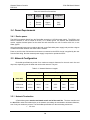
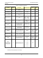
1
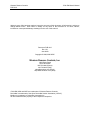
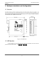
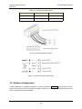
1782-JDM
DeviceNet™-Modbus Gateway
User’s Manual
Western Reserve Controls, Inc.
Western Reserve Controls
PUB 24.0
1782-JDM User’s Manual
Although every effort has been made to insure the accuracy of this document, all information is subject to
change without notice. WRC takes no liability for any errors in this document or for direct, indirect,
incidental or consequential damage resulting from the use of this manual.
Document PUB 24.0
Rev 1.01
June 2000
Copyright © 1999, 2000 WRC
Western Reserve Controls, Inc.
1485 Exeter Road
Akron OH 44306
330-733-6662 (Phone)
330-733-6663 (FAX)
[email protected] (Email)
http://www.wrcakron.com (Web)
1782-JDM, JDM and WRC are trademarks of Western Reserve Controls.
DeviceNet is a trademark of the Open DeviceNet Vendor Association (“ODVA”).
Modbus is a trademark of Schneider Automation Inc.
All other trademarks are property of their respective companies.
Western Reserve Controls
PUB 24.0
1782-JDM User’s Manual
TABLE OF CONTENTS
1
OVERVIEW ....................................................................................................................................................... 1
1.1
FEATURES ......................................................................................................................................................... 1
1.2
DEVICENET SYSTEM ARCHITECTURE ............................................................................................................... 2
1.3
JDM BASIC OPERATION ................................................................................................................................... 2
1.3.1 Polled I/O .................................................................................................................................................... 3
1.3.2 Explicit Messages ........................................................................................................................................ 3
1.4
DEFAULT DEVICE CONFIGURATION .................................................................................................................. 4
1.5
EDS.................................................................................................................................................................. 4
2
2.1
2.2
2.3
2.4
2.5
3
QUICK START .................................................................................................................................................. 5
HOW TO CHANGE THE NODE ADDRESS ............................................................................................................. 5
HOW TO CHANGE THE DEVICENET BAUD RATE ............................................................................................... 6
HOW TO INSTALL THE MODBUS DEVICE NETWORK .......................................................................................... 6
HOW TO READ MODBUS DEVICE INPUT DATA .................................................................................................. 6
HOW TO WRITE MODBUS DEVICE OUTPUT DATA ............................................................................................. 7
HARDWARE INSTALLATION AND CONFIGURATION ......................................................................... 8
3.1
OVERVIEW ........................................................................................................................................................ 8
3.2
LED OPERATION .............................................................................................................................................. 8
3.3
RS232/RS485 CONNECTOR.............................................................................................................................. 9
3.4
POWER REQUIREMENTS .................................................................................................................................. 10
3.4.1 Device power ............................................................................................................................................. 10
3.5
NETWORK CONFIGURATION ............................................................................................................................ 10
3.5.1 Network Termination................................................................................................................................. 10
3.5.2 DeviceNet Connection Wiring ................................................................................................................... 11
3.6
SOFTWARE CONFIGURATION ........................................................................................................................... 12
4
4.1
4.2
DEVICENET I/O ASSEMBLY FORMATS.................................................................................................. 15
OUTPUT DATA, MODBUS COMMAND .............................................................................................................. 15
INPUT DATA, MODBUS RESPONSE .................................................................................................................. 15
5
GENERAL SPECIFICATIONS...................................................................................................................... 17
6
ACCESSORIES AND OTHER WRC PRODUCTS ..................................................................................... 19
7
TROUBLESHOOTING................................................................................................................................... 20
LIST OF TABLES
TABLE 1-1 DATA MESSAGE OPTIONS ............................................................................................................................ 3
TABLE 2-1 ADDRESS SELECTION ................................................................................................................................... 5
TABLE 2-2 JDM SERIAL PORT CONNECTION ................................................................................................................. 6
TABLE 3-1 MODULE STATUS LED (LABELED MS) ...................................................................................................... 9
TABLE 3-2 NETWORK STATUS LED (LABELED NS)..................................................................................................... 9
TABLE 3-3 SERIAL PORT CONNECTIONS ...................................................................................................................... 10
i
Western Reserve Controls
PUB 24.0
1782-JDM User’s Manual
TABLE 3-4 NETWORK MAXIMUM LENGTHS ............................................................................................................... 10
TABLE 3-5 DEVICENET WIRING TERMINATION ......................................................................................................... 11
TABLE 3-6 DEVICENET CONDUCTOR SIZES ............................................................................................................... 12
TABLE 3-7 CONFIGURATION PARAMETERS .................................................................................................................. 13
TABLE 4-1 I/O ASSEMBLY OBJECT INSTANCE 2 DATA FORMAT – COMMAND ............................................................ 15
TABLE 4-2 I/O ASSEMBLY OBJECT INSTANCE 1 DATA FORMAT – RESPONSE ............................................................. 16
TABLE 6-1 WRC REPLACEMENTS, SPARE PARTS AND OTHER PRODUCTS .................................................................. 19
LIST OF FIGURES
FIGURE 1-1 1782-JDM .................................................................................................................................................. 1
FIGURE 3-1 1782-JDM OUTLINE ................................................................................................................................... 8
FIGURE 3-2 DEVICENET CABLE CONNECTOR ............................................................................................................... 12
FIGURE 3-3 DEVICENET CABLE SPECIFICATIONS ........................................................................................................ 12
ii
Western Reserve Controls
PUB 24.0
1782-JDM User’s Manual
PRELIMINARY
1 Overview
The 1782-JDM is a family of DeviceNet-to-Modbus interfaces that allows you to easily connect and
integrate a Modbus-capable device into a DeviceNet system.
The Modbus device’s real-time data is read and written as I/O by the DeviceNet Master via Polled I/O. The
devices set up parameters, if any, can be read and written with the Explicit Messaging technique. The
1782-JDM will operate with any compliant DeviceNet master software system or other device.
The JDM is defined as a Communications Adapter device on the DeviceNet system. It has a 3-pin plug
connector to cable to the Modbus RS232 or RS485 interface port on the MODBUS DEVICE and a 5-pin
pluggable DeviceNet connector for connections to the DeviceNet network. The DeviceNet baud rate
selection is done automatically by the device when it is powered up on a network. The JDM has one
assigned DeviceNet address which is set by a 6-position DIP switch on the unit. Other parameters are
software-configurable and are changed from their default values by third-party DeviceNet configuration
tools. Each JDM has 2 standard green/red DeviceNet LED’s for module status and network status and two
green LED’s to indicate RS485 transmit and receive activity.
All the Modbus device parameters are accessible for read or write over DeviceNet via the JDM, which
allows the user the option of using DeviceNet tools and software to define or monitor these parameters in
addition to other off-the-shelf or custom software utility using the Modbus port connection.
1782-JDM
DeviceNet Converter
KEY
RX
TX
GND
TOGGLE
ARM
1=LEFT
0=RIGHT
ADDR
=0
V+
CAN_H
N/C
CAN-L
V-
Figure 1-1 1782-JDM
1.1 Features
The JDM has the following features:
•
Translates messages and data between DeviceNet and Modbus devices
1
Western Reserve Controls
PUB 24.0
1782-JDM User’s Manual
•
Operates independently of operation of Modbus device
•
Forwards the message received without interpretation
•
Each JDM communicates with one or more Modbus devices
•
ODVA Conformance tested to DeviceNet Spec 2.0
•
DeviceNet Autobaud operation
•
Polled I/O
•
Explicit Messaging
•
All Modbus registers on target device are accessible
•
Upgrades to the Modbus device do not require updates to the JDM
•
Software Configurable Parameters for device operation
•
Address selection via DIP switches
•
DIN rail mount
•
Pluggable 5-pin DeviceNet connection
•
Pluggable RS232/RS485 3-pin connection
•
Choice of RS232, RS485 or isolated RS232 serial interface
•
Standard DeviceNet module and network status LED’s
•
Serial port transmit and receive LED’s
•
Powered from DeviceNet network
•
Optional isolated RS485 interface
1.2 DeviceNet System Architecture
A DeviceNet network is a distributed I/O system that may contain many different products from several
different vendors. Products may be configured uniformly, as clusters or as distributed clusters. Up to 64
devices, including the master, may be attached to a single DeviceNet network. Any of these, except the
master, may be a JDM. A typical system will include a master, such as a PLC or industrial PC, and
multiple slave devices, including a JDM with connected Modbus devices.
1.3 JDM Basic Operation
The JDM operates as the DeviceNet front-end gateway between the DeviceNet system and the Modbus
devices. It is a DeviceNet slave device that can be assigned by the system implementer to one specific
master. The DeviceNet Master can receive and send data to and from the JDM via the methods described
in this section. It interprets messages received from the DeviceNet connection and reformats and sends
them to the Modbus device. Likewise, it accepts and interprets responses from the Modbus device, which
are reformatted and passed back to the DeviceNet system as required.
The JDM has one DeviceNet address. All DeviceNet messages to the JDM itself (to read / write its internal
data) are sent to this address. All DeviceNet messages to and from the Modbus devices are sent to the
JDM DeviceNet address.
The JDM Parameter Object allows you to define the specific operation of each JDM. These parameters
include set-up for the serial comm link and the fault and idle actions and data.
Each Modbus device connected to the JDM has a Modbus address between 1 and 254. This address is
used by the host system and the JDM to identify which device on the Modbus network is being selected
2
Western Reserve Controls
PUB 24.0
1782-JDM User’s Manual
for each message. Therefore, each message to a Modbus device has 2 addresses associated with it – the
DeviceNet address of the JDM and the Modbus address of the specific device.
Table 1-1 Data Message Options
I/O Type
Polled
Modbus Device
Commands
√
Modbus
Status
√
Device
Cyclic
Bit-Strobe
Change-of-State
Explicit Message
√
Modbus Device
Parameters
The following sections describe how the data is accessed.
1.3.1 Polled I/O
The master can poll the run-time data used in the JDM. The communications is a two-part transaction:
there is a Poll Command from the host (with or without data) to the JDM and the JDM responds with a Poll
Response. When a poll command is received, input data are transmitted from the JDM to the host.
How do I send a poll command to write data?
The poll command can set multiple registers of data per output command, depending upon the Modbus
command used. First, define the Modbus command string desired to send to the Modbus device. Enter
this data in binary format – the normal format for RTU mode. This format is also used if in Modbus ASCII
mode – the JDM will translate from binary to ASCII. Do not include the leading colon (for ASCII mode) or
the CRC or LRC. Determine the number of bytes to be written, with the data in binary format. Then set up
your scanner to write the defined number bytes of data to the JDM plus one (1).
Any Modbus command and register that is appropriate to the target Modbus device are valid. See the
Modbus device’s user’s manual for more details on which commands are supported.
How do I send a poll command to read data?
The poll command can read multiple Modbus Device status registers’ data per poll command, as
supported by the device, up to a limit of 100 bytes of data on the DeviceNet message. First, set up your
scanner to read the number of bytes of data expected from the JDM plus two (2), depending upon the
command and number of register data desired. The command response from the Modbus device is
returned from the JDM to the DeviceNet master in response to a poll command.
1.3.2 Explicit Messages
As mentioned explicit messages are typically used to read and write configuration data, but they can be
used to access any available data in either the JDM or the Modbus device.
3
Western Reserve Controls
PUB 24.0
1782-JDM User’s Manual
1.4 Default Device Configuration
The JDM DeviceNet address is read from the switches and is set to 63 at the factory. All other parameters
are software settable. The default settings for the JDM are provided in the discussion of the Parameter
Object.
1.5 EDS
An EDS (Electronic Data Sheet), which describes the various parameters of the JDM, is shipped with your
device or is available on WRC’s web site: http://www.wrcakron.com/
4
Western Reserve Controls
PUB 24.0
1782-JDM User’s Manual
2 Quick Start
To quickly and easily install your JDM in your DeviceNet system, follow the instructions below. For
more details, see Section 2.3.
To Install and Establish DeviceNet Communications
1. Connect the DeviceNet cable to the 5-pin plug (supplied) according to DeviceNet cable wiring
specifications.
2. Make sure that the DeviceNet network is terminated properly. (See Section 3.5 below.)
3. The JDM Node Address (MacID) is set to 63 at the factory. Make sure no other device on the network
is set to 63, or change the JDM address to one that is not currently used (see below).
4. Use the autobaud feature of the JDM.
5. Make sure that there is power on the DeviceNet network and that it is plugged into a Master device.
6. Plug the DeviceNet cable into the JDM.
7. The JDM will undergo its initialization sequence, flashing both LEDs. After approximately 4 seconds,
the Module Status LED (labeled “MS”) will go on solid green and network LED will flash green.
8. The green Network Status LED (labeled “NS”) will go on solid once the Master recognizes the unit on
the link and allocates the connection.
9. The JDM is now operating on the network.
2.1 How to Change the Node Address
1. The address is set using the 6-position DIP switch block. They define the address as follows:
Table 2-1 Address Selection
Node
Address
0
1
2
3
4
5
…
62
63
1
2
32
OFF
OFF
OFF
OFF
OFF
OFF
16
OFF
OFF
OFF
OFF
OFF
OFF
ON
ON
ON
ON
Switch Positions
3
4
Switch Position Values
8
4
OFF
OFF
OFF
OFF
OFF
OFF
OFF
OFF
OFF
ON
OFF
ON
ON
ON
ON
ON
5
6
2
OFF
OFF
ON
ON
OFF
OFF
1
OFF
ON
OFF
ON
OFF
ON
ON
ON
OFF
ON
(A switch in the OFF position = a value of 0 and in the ON position = a 1.)
2. Switch setting changes do NOT take effect until the device is reset with either a device RESET
command (to the class 1 Identity object) or a power cycle.
5
Western Reserve Controls
PUB 24.0
1782-JDM User’s Manual
2.2 How to Change the DeviceNet Baud Rate
1. The baud rate defaults to autobaud. You can change the baud rate in software to a fixed baud rate
using your configuration tool or any command from the Master.
2. If you change the baud rate, the new baud rate will not become effective until the unit is power cycled
or a Reset command is received from the Master.
2.3 How to Install the Modbus Device Network
1. The communication between the Modbus device(s) and the 1782-JDM is an RS-232 3-wire full-duplex
link or an RS-485 network, using a 2-wire half-duplex differential signal between the devices.
2. Connect an appropriate cable to your Modbus device. See your Modbus device users manual for
details.
3. Connect the other end of the cable to the JDM using the 3-point terminal plug provided. See Error!
Reference source not found. below.
Table 2-2 JDM Serial Port Connection
Pin #
RS232
Signal
RS485
Signal
Designator
1
Transmit
Signal +
SIG+
2
Receive
Signal -
SIG-
3
Ground
Ground
GND
4. Turn on power to the Modbus device.
2.4 How to Read Modbus Device Input Data
1. Set up the poll input data field size in your Master’s scan table to be equal to or greater than the
number of bytes required for the largest Modbus message received from your device(s).
2. Set up a Poll Connection (Connection Instance 2) to the 1782-JDM from the Master.
3. Configure the serial port to read input data by setting the appropriate values in the Parameter Data,
described in Section 3.6.
st
4. Perform a poll function to the JDM. ASCII data will be received from the JDM. The 1 byte of the field
will be a “record number”, which will be incremented by the JDM each time a new record is received
nd
into the specific input port. The 2 byte contains the device or communication status.
5. The response data bytes will be returned in the mapped poll response data field. The data will be in
binary format and will represent the complete Modbus message, less checksum / CRC data and the
leading “:” (colon) (for ASCII mode).
6. The response will include two extra bytes of data. The first byte of the response will be a “record
counter” which is a counter generated by the JDM to mark the message with a sequential count value.
6
Western Reserve Controls
PUB 24.0
1782-JDM User’s Manual
Each time a new message is received at the JDM from the Modbus network, it will increment the
counter.
7. The second byte of the record will be a status byte. This is a combination of the status of the received
Modbus message and the JDM’s error detection system.
A typical response is as follows:
•
Record count or sequence number (1 byte)
•
Status / error data (1 byte)
•
Device’s Modbus address (1 byte)
•
Modbus command number (1 byte)
•
Modbus error/status value (1 byte)
•
Starting Modbus register address (2 bytes)
•
Number of data bytes (1 byte)
•
Input data (2 bytes per datum value)
•
1 Register data (2 byes)
•
2 Register data (2 byes)
•
3 Register data (2 byes)
st
nd
rd
2.5 How to Write Modbus Device Output Data
1. Configure the port to send output data by setting the size of the poll output buffer at the Master to
reflect the number of ASCII output bytes that will be sent to the ASCII.
2. Perform a poll function to the ASCII. ASCII data will be sent to the ASCII. The first byte of the field
must be a “record number”, which the host application must increment each time a new record is to
sent from the ASCII to the Modbus device. The bytes following this will be the ASCII data being sent to
the ASCII device.
The data sent to the JDM will typically contain the following info:
•
Record sequence number (1 byte)
•
Device’s Modbus address (1 byte)
•
Modbus command number (1 byte)
•
Beginning Register number (2 byes)
•
Number of registers (2 bytes)
•
Output data (2 bytes per datum value)
7
Western Reserve Controls
PUB 24.0
1782-JDM User’s Manual
3 Hardware Installation and Configuration
3.1 Overview
The ASCII contains two LEDs to indicate the status of the device and the status of the network. The
device can be connected to the main DeviceNet trunk line or to a drop line via screw terminations on the
open, pluggable 5-pin DeviceNet connector supplied with your unit. The serial link, RS232 or RS485, is
connected via an open, pluggable 3-pin connector.
0.984 (25)
3.540 (89.9)
0.394
(10)
1782-JDM
ADDRESS 1
SELECT 2
4
8
1=LEFT 16
32
0=RIGHT 63=ADDR
0
0
4
0
0
32
36=ADDR
DeviceNet
Modbus
CONVERTER
SG+
S+
SG -
S-
GND
G
1
0
0
8
0
0
9=ADDR
A
D
D
R
E
S
S
3.11(79)
V+
CAN_H
MS
N/C
NS
CAN_L
V-
2.920 (74.2)
0.160 (4.1)
Figure 3-1 1782-JDM Outline
3.2 LED Operation
A ASCII Multiplexer has two LEDs that provide visual status information to the user about the
product and the DeviceNet network. See Table 3-1 and Table 3-2.
8
Western Reserve Controls
PUB 24.0
1782-JDM User’s Manual
Table 3-1 Module Status LED (labeled MS)
LED State
Module Status
Meaning
OFF
No Power
There is no power through DeviceNet.
Green
Device Operational
ASCII is operating normally.
Flashing Green
Device in Standby
Flashing Red
Minor Fault
If in autobaud, ASCII is waiting for a sync
signal.
(If fixed baud mode, ASCII needs
commissioning. Future.)
Recoverable fault.
Red
Unrecoverable Fault
ASCII may need replaced.
Flashing Red/Green
Device Self-Testing
ASCII is in self-test mode.
Table 3-2 Network Status LED (labeled NS)
LED State
Module Status
Meaning
OFF
No Power / Not on-line
Flashing Green
On-line, not connected
Green
On-line
ASCII has no power or has not completed
the Dup_MAC_ID test.
ASCII is on-line but is not allocated to a
Master.
ASCII is operating normally.
Flashing Red
Connection time-out
Red
Critical link failure
One or more ASCII connections are timed
out.
ASCII has detected an error which makes it
incapable of communicating on the link.
(Bus off or Duplicate MAC ID).
3.3 RS232/RS485 Connector
Your Modbus device(s) are connected to the ASCII via 3-wire communications cable. See your Modbus
device User Manual for details on the specific connection.
9
Western Reserve Controls
PUB 24.0
1782-JDM User’s Manual
Table 3-3 Serial Port Connections
Pin #
RS232
Signal
RS485
Signal
Designator
1
Transmit
Signal +
SIG+
2
Receive
Signal -
SIG-
3
Ground
Ground
GND
3.4 Power Requirements
3.4.1 Device power
The ASCII is powered directly from the DeviceNet connection 11-25 Vdc power supply. The ASCII-1 and
ASCII-2 consume 67 mA of current at 24 Vdc, or 1.8 Watts, typical. The ASCII-3, the isolated RS-232
version, supplies isolated power for the serial link and consumes xxx mA of current at 24 Vdc, or xxx
Watts, typical.
Using the external power source reduces the load on the DeviceNet power supply and provides a degree
of electrical isolation between the ASCII and the network.
Power to and from the field actuators and sensors connected to the ASCII circuits is supplied by the user
from the field wiring. No other external power supply is required to operate the ASCII.
3.5 Network Configuration
DeviceNet specifications provide for a maximum network distances for the main trunk line and
drop lines, depending upon the baud rate used on the network. They are:
Table 3-4 Network Maximum Lengths
Trunk Line Length
Drop Length
Maximum Distance
Maximum
Cumulative
Baud Rate
Meters
Feet
Meters
Feet
Meters
Feet
125k baud
5OO m
164O ft
6m
2O ft
156 m
512 ft.
25Ok baud
25O m
82O ft
6m
2O ft
78 m
256 ft.
5OOk baud
1OO m
328 ft
6m
2O ft
39 m
128 ft.
3.5.1 Network Termination
A DeviceNet system must be terminated at each end of the trunk line. The host controller and
the last JDM or other DeviceNet device on the network must always be terminated to eliminate reflections,
even if only two nodes are present. The DeviceNet specifications for the terminating resistor are:
• 121 ohm
10
Western Reserve Controls
PUB 24.0
•
•
1782-JDM User’s Manual
1% metal film
1/4 Watt
An appropriate terminating resistor kit, WRC part number RM121DN, is included with your JDM.
Important: Per the DeviceNet spec -- do not terminate devices on drop lines.
3.5.2 DeviceNet Connection Wiring
The supplied DeviceNet connection plug accepts cable sizes from 12 AWG - 24 AWG. The
maximum wire size (12 AWG) has an area of 653O circular mils and the smallest (24 AWG) has an area
of 3265 circular mils.
Where not prohibited by local government or wiring regulations or company policy, multiple wires
can be inserted each connection point on the plug as long as the total wire area does not exceed that of a
12 AWG wire. Use the chart below as a guide.
Phoenix Contact recommends using the same size wires be used when connecting more than
one wire in a screw termination.
UL may require the use of crimped ferrules to connect multiple wires together.
Table 3-5 DeviceNet Wiring Termination
Wire AWG
Wire area (circular
mils)
Maximum Wires per
Terminal
12
653O
1
14
411O
1
15
3265
2
16
258O
2
18
162O
4*
2O
1O22
6*
22
645
9*
24
4O4
16 *
* WRC does not recommend using more than 2 wires in any wire terminal.
The conductor sizes for DeviceNet cables are:
11
Western Reserve Controls
PUB 24.0
1782-JDM User’s Manual
Table 3-6 DeviceNet Conductor Sizes
Function
Thick Wire
Thin Wire
Power
15 AWG
22 AWG
Signal
18 AWG
24 AWG
Figure 3-2 DeviceNet cable connector
Figure 3-3 DeviceNet cable specifications
3.6 Software Configuration
A ASCII Multiplexer is software-configured for several parameters. Table 3-7 below defines the legal
values and the default values for the device address (referred to as the device’s MacID), baud rate and
ASCII configuration selections available.
12
Western Reserve Controls
PUB 24.0
1782-JDM User’s Manual
Table 3-7 Configuration Parameters
Parameter
Param.
Instance
Description
Parameter Choices
Default
Setting
Default
Value
Modbus Mode
1
Modbus communications
protocol
0 = ASCII, 1 = RTU
ASCII
0
Device Rx Data Size
2
Max size of bytes received
from the Modbus device
0 – 100
48
48
Device Tx Data Size
3
Max size of bytes
transmitted to the Modbus
device
0 – 100
48
48
Modbus Baud rate
4
Serial link communications
speed
0 = 9600, 1 = 300, 2
= 600, 3 = 1200, 4 =
2400, 5 = 4800, 6 =
19.2k, 7 = 38.4k
9600
0
DeviceNet Baud
rate
5
DeviceNet communications
speed
0 = 125k, 1 = 250k, 2
= 500k, 3 =
Autobaud
Autobaud
3
Modbus Time-out
Time
6
Time to wait in 8 ms ticks
for a Modbus response
from the device before
declaring an error
0 = No time out, 1 –
255 = 8 ms – 2 sec
No time-out
0
Output Fault Action
7
Action to take upon a fault
of the DeviceNet
communications link
0 = No Action, 1 =
Transmit String
No Action
0
Output Fault Value /
string
8
The ASCII or binary string
sent to out the Modbus port
if Output Fault Action is 1.
<user-defined
string>
Read
Exception
Status
Command
0x01,
0x07
Output Idle Action
9
Action to take upon an Idle
condition of the DeviceNet
communications link
0 = No Action, 1 =
Transmit String
No Action
0
10
The ASCII or binary string
sent to out the Modbus port
if Output Idle Action is 1.
<user-defined
string>
Read
Exception
Status
Command
0x01,
0x07
7N2
0
Output Idle Value /
string
0 = 7,N, 2
1 = 7, O, 1
Serial
communications
framing format
11
Framing parameters for the
serial communications link
2 = 7, E, 1
3 = 8,N, 2
4 = 8, O, 1
5 = 8, E, 1
Definitions of these parameters are as follows:
13
Western Reserve Controls
PUB 24.0
1782-JDM User’s Manual
1.
Modbus Mode: The JDM can operate in either the ASCII or RTU mode for Modbus
communications.
2.
Rx Data Length: Maximum number of bytes expected from the remote Modbus device.
3.
Tx Data Length: Maximum number of bytes to be sent to the remote Modbus device
4.
Modbus Baud rate: The communications speed of the RS232 or RS485 link.
5.
DeviceNet Baud rate: The selection of the baud rate is independent of any other
parameter.
6.
Modbus Timeout: The amount of time the JDM waits for a command response from a
Modbus device before it declares an error due to a lack of response from the device. A
value of 0 indicates that this feature is not active.
7.
Output Fault Action: Selection to determine whether each output will hold its last state or
transmit the Modbus string identified in the next parameter upon a device fault.
8.
Output Fault Value/String: The message string the JDM will output after a Fault, if Fault
Value is selected above (hold last state is not selected). The default is a command to
Modbus address 0x01 with a Modbus command number 0x07, Read Exception Status.
9.
Output Idle Action: Selection to determine whether each output will hold its last state or
transmit the Modbus string defined in the next parameter if an Idle Command is issued by
the Master.
10.
Output Idle Value/String: The message string the JDM will output after an Idle
Command, if Idle Value is selected above (hold last state is not selected). The default is a
command to Modbus address 0x01 with a Modbus command number 0x07, Read
Exception Status.
11.
Serial Communications Framing Format: Selects which format of communications
protocol is used, with the valid selection indicated.
14
Western Reserve Controls
PUB 24.0
1782-JDM User’s Manual
4 DeviceNet I/O Assembly Formats
The following tables define the format of the DeviceNet data sent to and received from the JDM. The
exact format of the output and input data that is sent from and received at your DeviceNet master is
defined by the Modbus command used. The following tables provide the general format and illustrate the
differences between the ASCII and RTU modes. Review the Modbus spec or your Modbus device’s user’s
manual for more details.
4.1 Output Data, Modbus Command
Table 4-1 I/O Assembly Object Instance 2 Data Format – Command
Byte
(Offset value)
0
1
2
3
4
5
6
…
N
N+1
Data
Record number
Address
Command
Data www – LSB
Data www – MSB
Data xxx – LSB
Data xxx – MSB
Last data – LSB
Last data – MSB
4.2 Input Data, Modbus Response
The exact format of the input data that is received at your DeviceNet master is defined by the
Modbus command used. The following tables provide the general format and illustrate the differences
between the ASCII and RTU modes. Review the Modbus spec or your Modbus device’s user’s manual for
more details.
15
Western Reserve Controls
PUB 24.0
1782-JDM User’s Manual
Table 4-2 I/O Assembly Object Instance 1 Data Format – Response
Byte
(Offset value)
0
1
2
3
4
5
6
7
8
…
N
N+1
Data
Record number
Status
Address
Function/Command
Byte Count
Data xxx - LSB
Data xxx – MSB
Data yyy - LSB
Data yyy - MSB
Last data – LSB
Last data – MSB
16
Western Reserve Controls
PUB 24.0
1782-JDM User’s Manual
PRELIMINARY
5 General Specifications
Product:
1782-JDM – DeviceNet-to-Modbus Gateway
Description:
Communications gateway between a Modbus device over an RS232 or
RS485 network and a DeviceNet network. The family members include:
!" 1782-JDM-1 – RS232 serial interface
!" 1782-JDM-2 – RS485 serial interface
!" 1782-JDM-3 – Isolated RS232 serial interface
Device Profile:
General Purpose Discrete I/O, Class 0x07 hex, with objects:
- Identity (Class 01 hex)
- Message Router (Class 02 hex)
- DeviceNet (Class 03 hex)
- Assembly (Class 04 hex) – 2 instances
- Connection (Class 05 hex)
- Parameter (Class 0F hex) – 9 instances
- Modbus Object (Class 66 hex) – vendor-specific
DeviceNet Conformance:
Designed to conform to the ODVA DeviceNet Specification Volume I,
Version 2.0 and Volume II, Version 2.0.
Communications:
Predefined Master/Slave Connection Set, Group 2 Only Server
DeviceNet I/O Protocols:
Poll
DeviceNet Baud Rate:
Autobaud (default), 125k, 250, 500k - software selectable
DeviceNet Address selection: Address number 1 to 63, switch selectable (default = 63)
Switches 1 – 6
All switches OFF: address = 0
All switches ON: address = 63
DeviceNet Connection:
JDM: 5-pin pluggable header (male)
Phoenix Contact MSTBA 2.5/5-G-5.08/AU
DeviceNet Cable:
5-contact plug (female contacts) – color-coded
Phoenix Contact MSTB 2.5/5-ST-5.08/AU
(not included, user supplied)
Modbus Connection:
JDM: 3-pin pluggable header (male)
Phoenix Contact MSTBA 2.5/3-G-5.08/AU
Modbus Serial Cable: 3-contact plug (female contacts) – color-coded
Phoenix Contact MSTB 2.5/3-ST-5.08/AU
(not included, user supplied)
DeviceNet:
Baud rate selection:
Autobaud operation (default)
Fixed baud (software selectable) – 125k, 250k and 500k baud
Address selection:
Address number 0 to 63, switch selectable (default = 63)
Cable Connection:
JDM: 5-pin pluggable header (male)
17
Western Reserve Controls
PUB 24.0
1782-JDM User’s Manual
Phoenix Contact MSTBA 2.5/5-G-5.08/AU or equivalent
DeviceNet Cable: 5-contact plug (female contacts)
Phoenix Contact MSTB 2.5/5-ST-5.08/AU or equivalent (included)
Status Indicators:
Module Status: green/red bi-color LED
Network Status: green/red bi-color LED
Network Termination:
External terminating resistor (optional per user system configuration)
Serial port:
Baud rate: 300, 600, 1200, 2400, 4800, 9600, 19.2k, 39.4k baud
(software selectable)
Parity:
Odd, even or none (software selectable)
Data bits:
7 or 8 (software selectable)
Cable Connection:
JDM: 3-pin pluggable header (male)
Phoenix Contact MSTBA 2.5/3-G-5.08/AU or equivalent
Serial Cable: 3-contact plug (female contacts)
Phoenix Contact MSTB 2.5/3-ST-5.08/AU or equivalent (included)
Status Indicators:
Transmit Active: green LED
Receive Active: green LED
Voltage Isolation:
Optional 500V isolated RS232 version
Maximum power:
200 mA @ 11 Vdc - 90 mA @ 25V dc unregulated power supply, not
including Output loads (power provided by the DeviceNet network, or
Auxiliary 24VDC power)
Mounting:
DIN rail mount, EN50022
Size:
Depth:
Width:
Height:
Operating Temp:
0-60 ºC
Humidity:
0-95% RH, non-condensing
Agency Approvals:
UL listed (pending), CE (pending)
3.54” (90 mm)
0.98” (25 mm)
3.11” (79 mm)
18
Western Reserve Controls
PUB 24.0
1782-JDM User’s Manual
6 Accessories and Other WRC Products
The following components can be used with a 1782-JDM-x for replacements or spare parts, or as
complementary devices as a part of your DeviceNet system.
Table 6-1 WRC Replacements, Spare Parts and Other Products
Part
WRC Part Number
DIN rail
WRC 50022
Terminating resistor, axial lead
RM121DN
Terminal block connector plug, 18-position
KPELFP18210
Terminal block connector plug, 20-position
KPELFP20210
Discrete I/O block – 4 channels
1782-JDB4
Discrete I/O block – 8 channels
1781-JDB8
Analog Input block – 4 channels, 10-bit
1782-JDA4
Analog I/O block – 8 channels, 12-bit
1782-JDA8
DeviceNet to Serial I/O Gateway
1782-JDC
DeviceNet to Modbus Gateway
1782-JDM
Discrete I/O block – 24 channels
WRC1-JDB24
Discrete I/O block – 48 channels
WRC1-JDB48
Discrete I/O, Analog Input block – 24 DIO, 32 AI
WRC1-JDA/24
Discrete I/O, Analog Input block – 48 DIO, 32 AI
WRC1-JDA/48
Analog I/O block - 32 channels
WRC1-JDAIO
Discrete and Analog I/O block – 24 DIO, 32 AIO
WRC1-JDAIO/24
Discrete and Analog I/O block – 48IO, 32 AIO
WRC1-JDAIO/48
Discrete I/O block – 8 DIs, 8 DOs, 4 AIs
W5-JDM16-x
DeviceNet, CANopen Extender, DIN mount
WRC-CANX-DIN-DN
SDS Extender, DIN mount
WRC-CANX-DIN-SD
DeviceNet, CANopen Extender, DIN mount
WRC-CANX-DIN-C7
DeviceNet, CANopen Extender, NEMA box
WRC-CANX-NEM-AU
DeviceNet, CANopen Extender, NEMA box
WRC-CANX-NEM-DN
SDS Extender, NEMA box
WRC-CANX-NEM-SD
DeviceNet, CANopen Extender, Fiber Optic, NEMA
box
WRC-CANR-DF-DN
19
Western Reserve Controls
PUB 24.0
1782-JDM User’s Manual
7 Troubleshooting
This section identifies some of the common problem observed when commissioning or operating
a DeviceNet and JDM.
Problem:
JDM powers up, then the module status LED turns Red. JDM does not communicate over
the network.
Possible Solutions:
1. JDM has detected a duplicate MacID (DeviceNet address). Change the JDM’s MacID
to an unused address and cycle power.
Problem:
Module Status LED is solid Green
Network Status LED is flashing Green
Device will not communicate on the network
Possible Solutions:
1. Network does not have a terminating resistor. Add a 121 ohm resistor across the
CAN_H and CAN_L signals at the first and last nodes.
Problem:
Module Status LED is solid Red
Network Status LED is flashing Green or solid Green
Device will not perform serial I/O – does not return a poll response and ignores future
commands.
Possible Solutions:
1. JDM received an unintelligible response from the Modbus device and the time-out is
set to 0. Set the time-out value to a non-zero number greater than the longest
message time expected from the Modbus device.
Problem:
JDM does not receive a response from the Modbus slave.
Possible Solutions:
1. The ASCII-RTU mode selection is not correct.
2. The serial link baud rate does not match the Modbus device baud rate.
3. The communication parameters are not correct, including parity and number of data
bits.
4. The Modbus address is not correct in the I/O command.
5. The Modbus device may not support the Modbus specific commands being issued.
20