1
Dealer Knowledge Book
ER-A520
ER-A530
MODEL ER-A520 & ER-A530
Dealer Knowledge Book
Version 4
Contents
Category
SECTION 1. System Presets
Overview……………………………………………… ………………..…………………………………
Prior to Beginning……………………………………………..……………………………….………….
System Preset Job No……………………………………………………………………………………
SECTION 2. Free Key Layouts
Free Key Layout Set Up….………………………………………………………………………………
Free Key Layout Readings..……………………………………………………………..……………...
SECTION 3. File Allocation
Allocating Memory Files……………………………………………………….….……..……………….
SECTION 4. Peripherals
Peripheral Device Overview………………………………….……………….……….………………...
Coin Dispenser...…………………………………………………………...……………………………..
Scale………………………………………………………………………………………..………………
Printers…………………………………………………………………………………….……………….
Scanner…………………………………………………………………………………………………….
SECTION 5. PGM2 Mode Programming
Departments……………………………………………………………………………………………….
PLU/UPC…………………………………………………………………………………………………...
Cashiers……………………………………………………………………………………………………
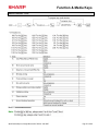
Function & Media Keys…………………………………………………………………………………..
Machine Settings……………………………………………………………………………………….....
SECTION 6. COM Communication
Online………………………………………………………………………………………………………
RS232 Communications Set Up………………………………………………………………………...
SECTION 7. Electronic Funds Transfer
Overview…………………………………………………………………………………………………...
DataTran 162SL Configuration………………………………………………………………………….
EFT Related Programming…………………………………………………...………………………….
SECTION 8. Utilities
Overview…………………………………………………………………………………………………...
02FD.EXE Installation/Usage……………………………………………………………………………
SECTION 9. SSP’s …………………………...……………………………………………………..……………………..
SECTION 10. Flash ROM …………………………………………………………………………………………………
SECTION 11. Logo Downloader Utility …………………………………………………………………………………..
Pg.
1
2
7
31
33
41
49
53
58
64
84
98
109
134
139
155
179
181
191
192
198
219
225
235
241
247
Notice:
Except as permitted by such license, no part of the software or documentation may be reproduced, stored in a retrieval
system, or transmitted, in any form or by any means, electronic, mechanical, recording, or otherwise, without the prior written
permission of Sharp Electronics Corporation.
The Data Tran software and/ or documentation referred to in this manual are furnished under the license by Datacap Systems,
Inc. and may only be used or copied in accordance with the terms of such license.
Designs and specification are subject to change without notice
Dealer Knowledge Book
TRADEMARKS
Data Tran and Data Tran SL are trademarks of Datacap Systems, Inc. All other trademarks
and registered marks are the property of their respective holders.
DISCLAIMER
The information contained in this document is furnished without assurance of
peripheral/software compatibility between Sharp POS products and the products of the
suppliers listed.
Product specifications change without notification (both Sharp and other supplier’s products).
Sharp POS does not undertake to update materials. It is the dealer’s responsibility to keep
current with all technical issues associated with these products.
NOTICE TO USERS
This manual is intended to assist authorized Sharp dealers, with learning and understanding
how to the install and provide support for the ER-A520 and ER-A530. Please read each
section carefully as it will provide helpful hints and recommendations that will make your time
more efficient and produce time saving results. This manual is not intended for end user
customers of authorized Sharp dealers.
Designs and specification are subject to change without notice
Section-1: System Presets
System Presets
Section-1: SRV Mode Programming
SRV-mode programmings consist of service programming jobs, which define the ER-A520/ERA530 system capabilities. The service program settings are printed on the Receipt / Journal
printer.
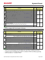
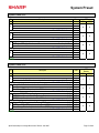
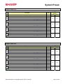
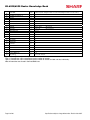
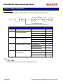
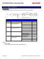
1. SRV-mode Program Readings:
List of SRV-mode Program Reports:
SRV-Mode Related Jobs: (X = indication of availability)
Job No.
Description
900
System Presets / Memory Allocation
950
Free Key – Function keys
951
Keyboard Layout – Dept & PLU Link Key Position
990
Special Service Patch Data
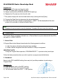
2. Entering the SRV-Mode
To enter SRV-mode programming
Procedure:
1) Place the mode switch to the SRV’ position
2) Place the AC power cord into the wall outlet
CAUTION:
Never enter the SRV mode in the middle of a transaction – severe damage may result to the sales
totals.
Specifications subject to change without notice: Revision date 10/07
Page 1 of 266
ER-A520/A530 Dealer Knowledge Book
Section-2: Prior to Beginning
The ER-A520/A530 POS terminal should be initialized by executing a master reset. The Program
and Master Reset operations are available in one of the following three types:
Type
Program Reset
Master Reset-1
Master-Reset-2
Description
Initializes the hardware and resident program without clearing
memory and totalizers
Initializes the hardware and clears the entire memory – restoring
factory initial values
Initializes the hardware and clears the entire memory – restoring
factory initial values and enabling free key layout of the ERA520/A530 “fixed keys”
1. Master Resets:
The Master Reset procedures are primarily performed during installation and setup of the ERA520 and ER-A530 model cash registers. Each has an important role when installing the
equipment.
Follow one the below procedures when you wish to perform a Master Reset.
1. General Rule:
Master Reset: Clears the entire memory and resumes initial values (default program).
Program Reset: Resumes the initial program without clearing memory.
There are 2 methods for performing a Master Reset operation.
1) Master Reset-1: Normal Master Reset (out of box setup).
Clears the entire memory and resumes initial values.
2) Master Reset-2: Enables the ability to change the layout fixed keys in addition to executing
the Master Reset-1.
Fixed Keys: [0] [1] [2] [3] [4] [5] [6] [7] [8] [9] [0] [00] [000] [CL] [.] [@/FOR] [SBTL] [CA/AT]
IMPORTANT NOTES:
During the Master Reset initialization, the following events should be noted.
1) ***MRS*** is displayed on the upper line of the operator display.
2) MASTER RESET*** is printed on the journal tape.
3) The buzzer will beep 3-times.
Page 2 of 266
Specifications subject to change without notice: Revision date 10/07
System Preset
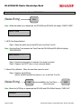
2. Master Reset-1 Operations:
There are two possible procedures to use when performing a Master Reset-1 operation.
Follow the below procedure when you wish to perform a program-reset (initialization).
Procedure A:
1) Place the mode switch to the SRV’ position.
2) Place the AC power cord into the wall outlet.
3) Depress and hold the [JOURNAL] feed key.
4) Turn the mode switch from SRV’ -- > SRV position.
Procedure B:
1) Remove the AC power cord from the outlet.
2) Place the mode switch to the SRV position.
3) Depress and hold the [JOURNAL] feed key.
4) Replace the AC power cord into the wall outlet.
Note:
***Procedure A must be used to reset the hardware. Procedure B cannot reset the hardware.
Master Reset-2 Operations:
There are two possible procedures to use in performing a Master Reset-2 operation.
Procedure A:
1) Place the mode switch to the SRV’ position.
2) Place the AC power cord into the wall outlet.
3) Depress and hold the [JOURNAL] & [RECEIPT] feed keys.
4) Turn the mode switch from SRV’ -- > SRV position.
***The operator display will show the fixed function keys
(starting with the [0] key).
5) Program the Fixed Keys by depressing the desired location(s).
6) Once the [CA/AT] key is placed on the keyboard, ***MRS*** will be displayed and the reset
process will continued as outlined in Master Reset-1.
Specifications subject to change without notice: Revision date 10/07
Page 3 of 266
ER-A520/A530 Dealer Knowledge Book
Procedure B:
1) Remove the AC power cord from the outlet.
2) Place the mode switch to the SRV position.
3) Depress and hold the [JOURNAL] & [RECEIPT] feed keys.
4) Replace the AC power cord into the wall outlet.
***The operator display will show the fixed function keys (starting with the [0] key).
5) Program the Fixed Keys by depressing the desired location(s).
6) Once the [CA/AT] key is placed on the keyboard, ***MRS*** will be displayed and the reset
process will continued as outlined in Master Reset-1.
Note:
***Procedure A must be used to reset the hardware. Procedure B cannot reset the hardware.
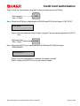
2. Program Reset:
The Program Reset (sometimes referred to as a “Service Reset”) may be achieved with the [SRV]
key (part no. LKGiM7113RCZZ).
1. General Rule:
A Program Reset should be performed under the following general conditions:
1) After the memory allocation setting has been modified.
2) When a device assignment has been modified in COM port assignment.
IMPORTANT NOTE:
During the Program Reset operation, PROGRAM RESET*** is printed on the journal tape.
Follow the below procedure when you wish to perform a program-reset (initialization).
2. Procedures:
Based on the SRV Job#926-B setting, there may be 3 possible procedures in performing a
Program Reset.
Procedure- A:
1) Place the mode switch to the SRV’ position.
2) Place the AC power cord into the wall outlet.
3) Turn the mode switch from SRV’ -- > SRV position.
Page 4 of 266
Specifications subject to change without notice: Revision date 10/07
System Preset
Procedure- B:
1) Remove the AC power cord from the outlet.
2) Place the mode switch to the SRV’ position.
3) Replace the AC power cord into the wall outlet.
4) Turn the mode switch clockwise to the SRV position (7 o’clock).
Procedure- C: (based on SRV Job#926-B)
1) Remove the AC power cord from the outlet.
2) Place the mode key in the PGM2 position.
3) Depress and hold the [RECEIPT] & [JOURNAL] feed keys.
4) Replace the AC power cord into the wall outlet while holding the keys.
Note:
***Procedure A must be used to reset the hardware. Procedures B and C cannot reset the
hardware.
CAUTION:
Never enter the SRV mode in the middle of a transaction – severe damage may result to the sales
totals.
Specifications subject to change without notice: Revision date 10/07
Page 5 of 266
ER-A520/A530 Dealer Knowledge Book
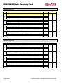
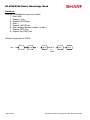
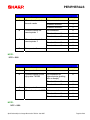
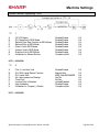
3. Recommended Set Up Procedures
To minimize unnecessary steps when installing the ER-A520 and ER-A530 model cash register,
please perform Job#971 (Memory Allocation), Job#900s (Service Parameters),
Job#950 (Free Key), Job#951 (Keyboard Link Position) followed by “All” PGM2 settings.
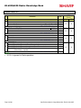
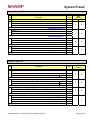
The below chart represents the SRV Job# Reference Descriptions.
SRV-Mode Related Jobs: (X = indication of availability)
Job No.
Description
901 – 929 System Parameters
980
930 - 939
Report Counters Z-Counters
942 – 943 GT Totalizers
969
944
PGM2 Mode Secret Code
948
Training Cashier Assignment
949
Training Mode Title Programming
950
Keyboard Layout – Function keys
951
Keyboard – Dept & PLU Keys
971
Memory File Allocation Programming
985
Euro Symbol Programming for the TM-295 Slip Printer
986
Domestic Currency Symbol Programming
987
Language Selection for Text Print
989
Resetting of all Counters and Totalizers
990
Special Service Patch
996, 998
Program Data Send/Receive Function
4. Service Mode Programming
Service mode programming is usually performed during the installation process. To change the
System Preset settings, the following key operation is required.
Page 6 of 266
Specifications subject to change without notice: Revision date 10/07
System Preset
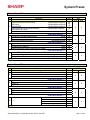
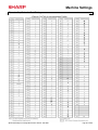
Section-3: System Preset Job No.
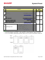
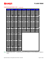
System Preset: 901
Bit
A
B
C
D
Description
Data
MRS Defaults
A520 A530
-------
Fixed = 0 (Not Used)
Enter SUM of Selection ----^
Tax System:
Auto Tax 1-4 & Manual Tax System / Canadian Tax (Type 1-10) / Canadian Tax (Type-11:
VAT-on-VAT)
Enter SUM of Selection ----^
Tax Rounding System:
- Singapore / Normal
Enter SUM of Selection ----^
Tab Setting:
- Decimal setting for display and print
Enter SUM of Selection ----^
0/6/7
8/0
3/2/1/0
0
0
0
0
0
0
2
2
NOTE:
• 901-C: The Singapore Tax Rounding method will round the tax to the nearest nickel.
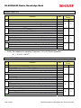
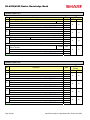
System Preset: 902
Bit
A
Description
Data
-------
-------
MRS Defaults
A520 A530
0
0
0
0
0
0
0
0
Enter SUM of Selection ----^
B
------Fixed = 0 (Not Used)
------Enter SUM of Selection ----^
----
-------
C
---Enter SUM of Selection ----^
D
----------
------Enter SUM of Selection ----^
NOTE:
Specifications subject to change without notice: Revision date 10/07
Page 7 of 266
ER-A520/A530 Dealer Knowledge Book
System Preset: 903
Bit
A
B
C
D
Description
Data
ECR Data Copy (SIO) All RAM data Send/Receive Baud Rate (bps):
38400/19200/9600
Enter SUM of Selection ----^
---Measure of Weight for Scale Entries
Kg/Lb
---Enter SUM of Selection ----^
Tare Weight Entry is allowed
Scale Weight System
Yes/No
1 Int. & 3 Dec./2 Int. & 2 Dec.
Enter SUM of Selection ----^
---Food Stamp System:
Food Stamp Forgiveness / Tax Payable in Food Stamps
Tax in Not Payable in Food Stamps / No Food Stamps
----
6/5/4
--2/0
----2/0
1/0
MRS
Defaults
A520
A530
5
5
0
0
0
0
0
0
--3/2/1/0
--Enter SUM of Selection ----^
NOTE:
• 903-A is applicable for the 02FD.exe utility (not online communications)
• Manual Scale Entry allowed (Version-C).
• To enabled Scale entries 906-D must be set = 1
System Preset: 904
Bit
Description
A
Date is printed
Fraction treatment at gasoline (OIL) q’ty calculation
----
B
Consecutive No. is printed
Decimal point position at gasoline (OIL) q’ty calculation
----
C
Fraction treatment at gasoline discount
-------
D
TAB for the gasoline unit price 0.00/0.000
Gasoline function
----
Data
No/Yes
Rounding/Raising to unit/Disregard
Enter SUM of Selection ----^
No/Yes
Enter SUM of Selection ----^
Rounding/Raising to unit/Disregard
Enter SUM of Selection ----^
Disable/Enable
Disable/Enable
4/0
----4/0
----0/1/2
----0/1
2/3
---
MRS
Defaults
A520
A530
0
0
0
0
0
0
0
0
Enter SUM of Selection ----^
NOTE:
• 904-A&B applies to Receipts, Slip, and Kitchen Print chits
Page 8 of 266
Specifications subject to change without notice: Revision date 10/07
System Preset
System Preset: 905
Bit
A
B
C
D
Description
Data
Tax4 Subtotal is printed on Trans. Reports
No/Yes
Gross Tax4 & Refund Tax4 Totals are printed on Trans. Reports
No/Yes
Net Tax4 Total is printed on Trans. Reports
No/Yes
Enter SUM of Selection ----^
Tax is printed when the Taxable Subtotal = $0.00
Yes/No
Tax is printed when GST is VAT
No/Yes
Tax is printed when Tax = $0.00
No/Yes
Enter SUM of Selection ----^
GST Exempt is printed on Trans. Reports
No/Yes
------Enter SUM of Selection ----^
4/0
2/0
1/0
Canadian Tax System:
Type10/Type9/Type8/Type7/Type6/Type5/Type4/Type3/Type2/Type1
4/0
2/0
1/0
4/0
-----9/8/7/6/
5/4/3/2/
1/0
MRS
Defaults
A520
A530
0
0
0
0
0
0
5
5
Enter SUM of Selection ----^
NOTE:
• 905-C is related to 905-D the Canadian Tax System
System Preset: 906
Bit
A
B
C
D
Description
Data
Dept. & PLU/UPC Codes are printed
Yes/No
PLU/UPC (EAN) Stock System:
Entry is Inhibited/Error Message and Operation continues/Allowed
Enter SUM of Selection ----^
Bottle Return Function is Enabled
Yes/No
Hash Dept. is Enabled
Yes/No
---Enter SUM of Selection ----^
Multiplication System:
Split-Price/Successive Multiplication/Multiplication
Enter SUM of Selection ----^
PLU/UPC (EAN) Price Look Up at Refund Entry
No/Yes
Presetting of the Consecutive No. is Enabled
No/Yes
Fractional Qty System is enabled (3 decimal places)
Yes/No
Enter SUM of Selection ----^
4/0
2/1/0
4/0
2/0
---
2/1/0
4/0
2/0
1/0
MRS
Defaults
A520
A530
0
0
0
0
2
2
0
0
NOTE:
• 906-D must not be changed until after totalizers are reset (Qty 0 Æ 0.000 & vice-versus).
• Fractional entries are disabled when a SCALE is enabled in PGM2 Job #2690 programming.
• 906-D must be set = 1 to enable “SCALE”.
Specifications subject to change without notice: Revision date 10/07
Page 9 of 266
ER-A520/A530 Dealer Knowledge Book
System Preset: 907
Bit
Description
A
---Fixed = 0
----
B
---UPC (EAN) Code Printing on Journal
UPC (EAN) Code Printing on Receipt
C
X Report is Enforced prior to Ind./All Cashier CCD
---Minus Dept. and PLU/UPC (EAN) items are Enabled
Data
-------
MRS
Defaults
A520
A530
0
0
0
0
1
1
0
0
Enter SUM of Selection ----^
D
No/Yes
No/Yes
Enter SUM of Selection ----^
Yes/No
Yes/No
Enter SUM of Selection ----^
CCD Compulsion on ALL Server
For Individual Server CCD
Non-Compulsory CCD
--2/0
1/0
4/0
2/0
1/0
0
1
2
Enter SUM of Selection ----^
NOTE:
• To enable Coupon PLU items 907-D must be set = 1
System Preset: 908
Bit
Description
A
GT1 is printed on the Trans.-Z Report
GT2 is printed on the Trans.-Z Report
GT3 is printed on the Trans.-Z Report
B
GT1 is printed on the Trans.-X Report
GT2 is printed on the Trans.-X Report
GT3 is printed on the Trans.-X Report
C
VOID-mode operations affect the Hourly Report
X//Z1 Reports may taken in X2/Z2 Mode
Consecutive No. is Reset upon a Trans.-Z Report
D
X/Z Report Printing:
---Trans.-Z1 Report resets the GT
Data
No/Yes
No/Yes
No/Yes
Enter SUM of Selection ----^
Yes/No
Yes/No
Yes/No
Enter SUM of Selection ----^
Yes/No
No/Yes
Yes/No
Enter SUM of Selection ----^
Journal only/Receipt & Journal
Yes/No
Enter SUM of Selection ----^
4/0
2/0
1/0
4/0
2/0
1/0
4/0
2/0
1/0
4/0
--1/0
MRS
Defaults
A520
A530
0
0
0
0
0
0
0
0
NOTE:
• 908-D: The X/Z Report printing option does not apply to Individual Cashier Report
Page 10 of 266
Specifications subject to change without notice: Revision date 10/07
System Preset
System Preset: 909
Bit
Description
A
---Training GT is printed on the Trans.-X Report
Training GT is printed on the Trans.-Z Report
B
PLU/UPC (EAN) Item Data is printed on the Z Report
-------
C
VOID-mode & MGR VOID is printed on the Trans.-Z2 Report
VOID-mode & MGR VOID is printed on the Trans.-Z1 Report
----
D
---Fixed = 0
----
Data
Yes/No
No/Yes
Enter SUM of Selection ----^
No/Yes
Enter SUM of Selection ----^
No/Yes
No/Yes
--2/0
1/0
4/0
----4/0
2/0
---
MRS
Defaults
A520
A530
2
2
0
0
0
0
0
0
Enter SUM of Selection ----^
------Enter SUM of Selection ----^
NOTE:
• 909-B: No Sales Data is printed for the PLU/UPC (EAN)-Z Report when = 4
System Preset: 910
Bit
A
Description
---Overlapped Cashier Function
---Cashier Code Display
B
Auto Sign Off at the End of the Transaction
Data
Yes/No
Enter SUM of Selection ----^
Appear/Hidden
Yes (Everytime) / No
After Cashier Z1 Only
----
--1/0
---
MRS
Defaults
A520
A530
0
0
2
2
0
0
4
4
2/0
1/0
---
Enter SUM of Selection ----^
C
---Fixed = 0
----
D
(Fixed): Server/Cashier system is code entry
-------
------Enter SUM of Selection ----^
4
----Enter SUM of Selection ----^
NOTE:
• 910-A: The Cash drawer opening is based on the Individual Server preset
Specifications subject to change without notice: Revision date 10/07
Page 11 of 266
ER-A520/A530 Dealer Knowledge Book
System Preset: 911
Bit
A
Description
------Fractional Qty System:
Data
Ignored/Round-Up/Round-Off
Enter SUM of Selection ----^
Yes/No
B
C/D Check of UPC (EAN)
-------
C
---Fixed = 0
----
D
Enter SUM of Selection ----^
RECEIPT/SLIP header format
Format 1: Normal sized Consec. #, Server Name and code
Format 2: Double-sized Consec. #, normal sized Server Name and code
Format 3: Double-sized Consec. #, and Server code
(Server Name not printed)
Enter SUM of Selection ----^
----2/1/0
4/0
-----
MRS
Defaults
A520
A530
0
0
0
0
0
0
0
0
Enter SUM of Selection ----^
-------
0
2
4
NOTE:
• 911-A: Is ignored for Scale operations
Page 12 of 266
Specifications subject to change without notice: Revision date 10/07
System Preset
System Preset: 912
Bit
A
B
C
D
Description
------Date Print Format
------Time Clock System
Receipt After-Transaction Format
Copy Receipt Function is Enabled
Receipt Footer Print Control
Logo Message Control:
Data
YYMMDD/DDMMYY/MMDDYY
Enter SUM of Selection ----^
24-Hour System/12-Hour System
Enter SUM of Selection ----^
Detailed/Totals only
Yes/No
By Media Preset/All Receipts
Enter SUM of Selection ----^
3-Line Header – No Logo Graphic Stamp
Graphic Logo Stamp only
Graphic Logo Stamp & 3-Line Footer
6-Line Header – No Stamp
Graphic Logo and 3-Line Header
3-Line Header – No Stamp/3-Line Footer
Enter SUM of Selection ----^
----2/1/0
----1/0
4/0
2/0
1/0
0
1
2
3
4
5
MRS
Defaults
A520
A530
0
0
0
0
6
6
1
0
NOTE:
• 912-D: The Graphic Logo STAMP – Must use SDW to upload Graphical Logos to the ECRs.
• 912-D: The Graphic Logo bitmap should be 288 dots (w) x 130 dots (h) and black & white only.
Specifications subject to change without notice: Revision date 10/07
Page 13 of 266
ER-A520/A530 Dealer Knowledge Book
System Preset: 913
Bit
A
B
C
D
Description
Data
------VP Total Amounts Contains:
Tendered Amount/Total Amount
Enter SUM of Selection ----^
Subtotal is printed when the [SBTL] key is depressed
Yes/No
MDSE Subtotal is printed when the [MDSE] key is depressed
Yes/No
Escaping Compulsory VP and SLIP print is Enabled
Yes/No
Enter SUM of Selection ----^
---Error-Tone System
Until [CL] is depressed/2 seconds
Keyboard Buffering is Enabled
No/Yes
Enter SUM of Selection ----^
Compulsory Drawer Closed prior to operation is enabled
Yes/No
Error System
“Misoperation”/One-Shot Error Only
Key Touch-Tone is enabled
No/Yes
Enter SUM of Selection ----^
----1/0
4/0
2/0
1/0
--2/0
1/0
4/0
2/0
1/0
MRS
Defaults
A520
A530
0
0
1
1
0
0
4
4
NOTE:
• 913-B: The sequence for escaping “Compulsory” VP or SLIP print operations:
Æ [.] Æ [SLIP or PRINT]
System Preset: 914
Bit
A
B
C
D
Description
Receipts are printed upon [NO SALE] operations
The [NO SALE] function is combined with the [CASH] key
Tax Delete function is Enabled
Data
No/Yes
Yes/No
Yes/No
Enter SUM of Selection ----^
4/0
2/0
1/0
------The [NO SALE] function is allowed after a Non-Add No. entry
Yes/No
Enter SUM of Selection ----^
---VOID-mode is Enabled
No/Yes
Non-Add # Entry is Compulsory at the beginning of each Trans.
Yes/No
Enter SUM of Selection ----^
Manual Tax entry is Enabled
No/Yes
Check-Cashing function is Enabled
Yes/No
Non-Add # Entry is Enabled
No/Yes
Enter SUM of Selection ----^
----1/0
--2/0
1/0
4/0
2/0
1/0
MRS
Defaults
A520
A530
1
1
1
1
0
0
0
0
NOTE:
Page 14 of 266
Specifications subject to change without notice: Revision date 10/07
System Preset
System Preset: 915
Bit
A
Description
Data
------Fixed = 0
-------
MRS
A520
A530
0
0
0
0
0
0
0
0
Enter SUM of Selection ----^
B
---Fixed = 0
----
------Enter SUM of Selection ----^
C
---SBTL (-) or SBTL (%) within the same Transaction
Once/Any No. Times
--2/0
Enter SUM of Selection ----^
D
Fixed = 0
-------
------Enter SUM of Selection ----^
NOTE:
System Preset: 916
Bit
A
B
C
D
Description
------Print when the No. Text Characters overlap the Amount
Charge Media Finalization when the Amount = $0.00
---Food Stamp SBTL is Compulsory before FS-Tender
Data
2-Line/Truncate
Enter SUM of Selection ----^
Yes/No
Yes/No
Enter SUM of Selection ----^
Allow the MDSE SBTL to go Negative
No/Yes
[SBTL] Entry is Compulsory before Tendering Finalization
Yes/No
[SBTL] Entry is Compulsory before Direct Finalization
Yes/No
Enter SUM of Selection ----^
Coupon PLU Totalizer prints on the Trans.-(X/Z) Reports
No/Yes
NET Sales SBTL (NET1) is printed on the Trans.-(X/Z) Reports
No/Yes
Check-Change Totalizer is printed on the Trans.-(X/Z) Reports
No/Yes
Enter SUM of Selection ----^
----1/0
4/0
--1/0
4/0
2/0
1/0
4/0
2/0
1/0
MRS
Defaults
A520
A530
1
1
4
4
0
0
0
0
NOTE:
Specifications subject to change without notice: Revision date 10/07
Page 15 of 266
ER-A520/A530 Dealer Knowledge Book
System Preset: 917
Bit
A
B
C
D
Description
Data
Tax1 Subtotal is printed on Trans. Reports
No/Yes
Gross Tax1 & Refund Tax1 Totals are printed on Trans. Reports
No/Yes
Net Tax1 Total is printed on Trans. Reports
No/Yes
Enter SUM of Selection ----^
Tax2 Subtotal is printed on Trans. Reports
No/Yes
Gross Tax2 & Refund Tax2 Totals are printed on Trans. Reports
No/Yes
Net Tax2 Total is printed on Trans. Reports
No/Yes
Enter SUM of Selection ----^
Tax3 Subtotal is printed on Trans. Reports
No/Yes
Gross Tax3 & Refund Tax3 Totals are printed on Trans. Reports
No/Yes
Net Tax1 Total is printed on Trans. Reports
No/Yes
Enter SUM of Selection ----^
Total Tax is printed on the Trans.-(X/Z) Reports
No/Yes
Gross & Ref. Manual Tax Totals are printed on Trans. Reports
No/Yes
Net Manual Tax Totalizer is printed on Trans.-(X/Z) Reports
No/Yes
Enter SUM of Selection ----^
4/0
2/0
1/0
4/0
2/0
1/0
4/0
2/0
1/0
4/0
2/0
1/0
MRS
A520
A530
0
0
0
0
0
0
0
0
NOTE:
System Preset: 918
Bit
A
B
C
D
Description
Assoc. PLU Text of Combo Meals is printed
nd
Direct-Tender for 2 or subsequent tender is allowed
Combo Meal Kitchen Printer printing is by
Data
No/Yes
Yes/No
Combo Meal’s KP/by PLU’s KP
Enter SUM of Selection ----^
4/0
2/0
1/0
---PLU Text is printed in RED when the unit price is $0.00
Yes/No
Fractional entries allowed for non-Scalable Dept. & PLU items
No/Yes
Enter SUM of Selection ----^
---Kitchen Printer output Groups Like Items
No/Yes
Kitchen Printer output prints Dept. & PLU Text in Double-Sized
Yes/No
Enter SUM of Selection ----^
Tip paid includes cash tip
No/Yes
Clearing of tip totalizer at server Z1 report
Yes/No
Printing of tip totalizer on the server report
Yes/No
Enter SUM of Selection ----^
--2/0
1/0
--2/0
1/0
4/0
2/0
1/0
MRS
A520
A530
2
2
2
2
3
3
3
3
NOTE:
Page 16 of 266
Specifications subject to change without notice: Revision date 10/07
System Preset
System Preset: 919
Bit
A
Description
Guest Check System is Guest Look-up
PB Look-up
Manual PB-CB
Guest Check/PB Look-up code upon Reorder
(Only when 919-B =0 or 4)
Data
Compulsory/Non-compulsory
Compulsory/Non-compulsory
Compulsory/Non-compulsory
Compulsory/Non-compulsory
MRS
A520
A530
0
0
4
4
0
0
0
0
5/4
3/2
1/0
1/0
----
B
C
D
Cashier No. is Checked at PBLU Reorder
---Guest Check Number-System Entry
Enter SUM of Selection ----^
No/Yes
Manual/Auto-Generate
Enter SUM of Selection ----^
---[PBLU] Entry is Compulsory
Amount Prints when PLU/UPC (EAN) Unit Price is $0.00
Yes/No
Yes/No
Enter SUM of Selection ----^
Normal SBTL is printed in addition to the Conversion SBTL
No/Yes
---Foreign Currency Format
Omit Decimal Digits/Not
Enter SUM of Selection ----^
4/0
--1/0
--2/0
1/0
4/0
--1/0
NOTE:
System Preset: 920
Bit
Description
A
Combine like items for GLU items printed on a Bill
-------
B
---Fixed = 0
----
C
----------
Data
No/Yes
0/4
-----
MRS
A520
A530
0
0
0
0
0
0
0
0
Enter SUM of Selection ----^
------Enter SUM of Selection ----^
------Enter SUM of Selection ----^
D
---------
---Enter SUM of Selection ----^
NOTE:
Specifications subject to change without notice: Revision date 10/07
Page 17 of 266
ER-A520/A530 Dealer Knowledge Book
System Preset: 921
Bit
A
Description
Data
Convert UPC-E to UPC-A Code
-------
Yes/No
4/0
-----
MRS
A520
A530
0
0
0
0
0
0
0
0
Enter SUM of Selection ----^
Fixed = 0
-------
B
Bill printing method
Items are printed and deleted/Items reprint each bill
C
D
Tip paid is automatically executed upon Ind. Server/Cashier resetting report
when a Tip exists.
Yes/No
0/1
----0/4
-----
Enter SUM of Selection ----^
NOTE:
System Preset: 922
Bit
Description
A
Fixed = 0
-------
B
Type coin dispenser can issue $1 coins
-------
C
------Fixed = 0
D
------Fixed = 0
Data
------Enter SUM of Selection ----^
No/Yes
0/1
-----
MRS
Defaults
A520
A530
0
0
0
0
0
0
0
0
Enter SUM of Selection ----^
------Enter SUM of Selection ----^
------Enter SUM of Selection ----^
NOTE:
Page 18 of 266
Specifications subject to change without notice: Revision date 10/07
System Preset
System Preset: 923
Bit
Description
A
------(Fixed)
B
(Fixed)
-------
C
---(Fixed)
(Fixed)
D
(Fixed)
(Fixed)
Data
-------
MRS
Defaults
A520
A530
0
0
0
0
0
0
0
0
Enter SUM of Selection ----^
----Enter SUM of Selection ----^
----Enter SUM of Selection ----^
----Enter SUM of Selection ----^
NOTE:
System Preset: 924
Bit
A
Description
Data
------(Fixed)
-------
MRS
A520
A530
0
0
0
0
0
0
0
0
Enter SUM of Selection ----^
B
(Fixed)
-------
C
---(Fixed)
(Fixed)
------Enter SUM of Selection ----^
------Enter SUM of Selection ----^
-----
D
Enter SUM of Selection ----^
NOTE:
Specifications subject to change without notice: Revision date 10/07
Page 19 of 266
ER-A520/A530 Dealer Knowledge Book
System Preset: 925
Bit
Description
Data
-------
A
----
MRS
Defaults
A520
A530
0
0
0
0
0
0
0
0
Enter SUM of Selection ----^
----
-------
B
Enter SUM of Selection ----^
C
Enter SUM of Selection ----^
----
-------
D
Enter SUM of Selection ----^
NOTE:
System Preset: 926
Bit
Description
A
---Direct Voids and the Voided item is printed on the KP
Past Voids and the Voided item is printed on the KP
B
Program Reset via PGM2-Mode is Enabled
Refunded Data is sent to the KP
----
Data
No/Yes
No/Yes
Enter SUM of Selection ----^
Yes/No
No/Yes
--2/0
1/0
4/0
2/0
---
MRS
Defaults
A520
A530
0
0
0
0
0
0
0
0
Enter SUM of Selection ----^
Fixed = 0
-------
C
Enter SUM of Selection ----^
D
Fixed = 0
-------
----Enter SUM of Selection ----^
NOTE:
• When REFUND Data is preset to print to the KP. It will print in RED.
• When REFUND Data is preset NOT to print to the KP. It will print in BLACK.
Page 20 of 266
Specifications subject to change without notice: Revision date 10/07
System Preset
System Preset: 927
Bit
A
Description
Data
Fixed = 0
-------
-------
MRS
Defaults
A520
A530
0
0
0
0
0
0
0
0
Enter SUM of Selection ----^
B
Fixed = 0
-------
C
Fixed = 0
-------
D
Fixed = 0
-------
------Enter SUM of Selection ----^
------Enter SUM of Selection ----^
------Enter SUM of Selection ----^
NOTE:
System Preset: 928
Bit
A
B
C
D
Description
------Slip Logo is printed on Slip Printer
---Validation Message is printed on Slip for Checks & Charges
Header Line is printed on Slip on Reorder Entries
Data
Yes/No
Enter SUM of Selection ----^
Yes/No
No/Yes
Enter SUM of Selection ----^
PLU/UPC (EAN) is printed on the [BILL] when the unit price = $0.00
No/Yes
Combo Meal Individual PLU Item Text is printed on the [BILL]
No/Yes
---Enter SUM of Selection ----^
Compulsory Bill Print System:
Compulsory for GLU/PBLU entries
Compulsory for every entry
Compulsory based on Media key preset
Enter SUM of Selection ----^
----1/0
--2/0
1/0
4/0
2/0
---
2
1
0
MRS
Defaults
A520
A530
0
0
0
0
0
0
0
0
NOTE:
Specifications subject to change without notice: Revision date 10/07
Page 21 of 266
ER-A520/A530 Dealer Knowledge Book
System Preset: 929
Bit
A
Description
Data
------KP Print format for Media Keys
B
Detailed/Summary
Enter SUM of Selection ----^
Server, Transaction resetting allowed with open Guest Checks.
Yes/No
----
C
When Closed Check file is full
----
Enter SUM of Selection ----^
Inhibit registration/Continue
----1/0
1/0
--0
0/1
-----
MRS
Defaults
0
0
0
0
0
0
0
0
Enter SUM of Selection ----^
--D
Taxable Status of PLU/UPC (EAN),
SET at “Non-Taxable” by PGM
mode
----
Taxable Status of PLU/UPC set
According to its Associated
Department
0/1
---
Enter SUM of Selection ----^
NOTE:
System Preset: 980
Bit
A
B
C
D
Description
Data
------Fixed = 0
----0
Enter SUM of Selection ----^
------HASH department entries are added to the Hourly Report
Yes/No
Enter SUM of Selection ----^
------Fixed = 0
Enter SUM of Selection ----^
---Fixed = 0
----1/0
----0
--0
0
MRS
Defaults
A520 A530
0
0
0
0
0
0
0
0
Enter SUM of Selection ----^
NOTE:
Page 22 of 266
Specifications subject to change without notice: Revision date 10/07
System Preset
Reset Report Counters – Z1/Z2
930: Z1 General Report Counter
931: Hourly Z1 Report Counter
934: PLU Z1 Report Counter
935: Cashier Z1 Report Counter
936: GLU/PBLU Z1 Report Counter
937: Z2 General Report Counter
939: Daily Net Z2 Report Counter
942: GT2 (Positive GT)
943: GT3 (Negative GT)
969: Training GT
Note: The Net GT is obtained from GT2 and GT3 calculations
MRS = 0000000000000
Specifications subject to change without notice: Revision date 10/07
Page 23 of 266
ER-A520/A530 Dealer Knowledge Book
PGM-2 Mode Secret Code Programming
MRS = 0000
Server/Cashier Training Programming
XX: Cashier/Server Code
MRS = 00
Training Mode Title Programming
MRS = **TRAINING**
Page 24 of 266
Specifications subject to change without notice: Revision date 10/07
System Preset
Euro Symbol Programming
X: 0 = “spaces”
1 = Euro Symbol
MRS = 0 (spaces)
Domestic Currency Symbol
MRS = **$**
Note: The characters are entered using the programming key layout or by entering the numeric
codes shown on page 20. This symbol is printed with positive amounts of domestic
currency and will be printed to the left-side of the amount.
Specifications subject to change without notice: Revision date 10/07
Page 25 of 266
ER-A520/A530 Dealer Knowledge Book
Language Setting For Text
X: 0 = English Text
1 = French Text
2 = Spanish Text
MRS = 0 (English)
Note: The following text is changed upon the setting above:
- FUNCTION text
- CASHIER text
- MESSAGE text (e.g. Logo, etc.)
Resetting of all Counters and Totalizers
Page 26 of 266
Specifications subject to change without notice: Revision date 10/07
System Preset
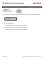
System Preset Reading – SRV Mode
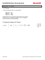
1. Procedures:
1) Place the SRV key to the SRV-Mode position
2) Enter the following sequence:
900
@
CASH
2. Print Out:
Specifications subject to change without notice: Revision date 10/07
Page 27 of 266
Section-2: Free Key Layouts
Free Key Layouts
Function Key Layout
XXX: Function No. 1-130
: 999 (for inhibiting a key)
MRS = Standard “out-of-the-box” key layout
Note: If the “fixed” function keys are accidentally placed in the wrong position, it may be
necessary to restore the MRS default keyboard in order to continue.
Note: Only the keyboard layout is affected; PGM2 Mode data are retained.
Function Key Layout
XXX: 1-82 (ER-A520)
: 1-151 (ER-A530)
: 999 (for inhibiting a key location)
MRS = Standard “out of box” key layout
Note: The Key No. programmed in this programming will be used in the PGM2 mode
programming for assigning direct Dept. and/or PLU keys on the keyboard.
Specifications subject to change without notice: Revision date 10/07
Page 31 of 266
ER-A520/A530 Dealer Knowledge Book
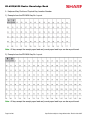
Function Key Reference Chart
1. ER-A520
Note: The
shaded keys are fixed and cannot be assigned to Key Functions.
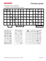
2. ER-A530
Note: The
Page 32 of 266
shaded keys are fixed and cannot be assigned to Key Functions.
Specifications subject to change without notice: Revision date 10/07
Free Key Layouts
Free Key Layout Reading – SRV Mode
2. Procedures:
1) Place the SRV key to the SRV-Mode position
2) Enter the following sequence:
950
@
CASH
Specifications subject to change without notice: Revision date 10/07
Page 33 of 266
ER-A520/A530 Dealer Knowledge Book
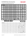
3. Keyboard Key Positions: Physical Key Location Number
1) Example from the ER-A520 Key No. Layout:
Note: All keys except the receipt paper feed and journal paper feed keys can be re-positioned.
2) Example from the ER-A530 Key No. Layout:
Note: All keys except the receipt paper feed and journal paper feed keys can be re-positioned.
Page 34 of 266
Specifications subject to change without notice: Revision date 10/07
Free Key Layouts
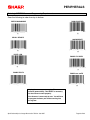
4. Reference Free Keys to Keyboard:
1) Example from the ER-A520 default Key Layout:
Receipt
Journal
NC
SLIP
RCPT
PBLU
5
10
15
CONV
RA
FINAL
4
9
%1
PO
16
14
22
21
20
TAX
3
8
13
%2
(-)
TAX
SHIFT
12
2
7
RFND
VOID
1
6
19
18
#/TM
11
KEY NO.
CASH
#
PLU/
UPC
PLU/
UPC
28
34
40
@/FOR
.
CL
27
33
7
8
26
32
4
5
6
25
31
37
1
2
3
24
0
17
23
30
0
39
46
45
9
38
36
44
43
42
00
29
34
FREE FUNCTION KEY
Specifications subject to change without notice: Revision date 10/07
41
PRICE
CHANGE
PRICE
CHANGE
AMT
INQ
FS
SHIFT
AUTO
1
52
58
52
70
76
82
FS
TEND
AUTO
2
75
81
NS
CH1
005
010
015
020
51
57
63
69
004
009
014
019
50
56
62
68
003
008
013
018
49
55
61
67
73
79
002
007
012
017
MDSE
SBTL
SBTL
48
54
001
006
47
53
60
011
59
66
0016
65
74
CHK
80
CH2
72
78
CA/AT
CA/AT
71
77
DEPT NO. EX. DEPT 7
Page 35 of 266
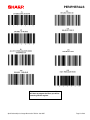
ER-A520/A530 Dealer Knowledge Book
2) Example from the ER-A530 Default Key Layout:
RCPT
JRNL
91
92
93
94
95
96
97
98
99
100
L1
L2
L3
79
80
25
81
34
82
43
83
52
84
61
85
70
86
79
87
88
88
97
89
106
90
115
RCPT
124
%
133
(-)
8
67
16
68
24
69
33
70
42
71
51
72
60
73
69
74
78
75
87
76
96
77
105
78
114
VOID
123
INQ
7
56
15
57
23
58
32
59
41
60
50
61
59
62
68
63
77
64
86
65
95
66
113
RFND
6
45
14
46
22
47
31
48
40
49
49
50
58
51
67
52
76
53
85
54
94
55
104
SERV
#
103
@/FOR
112
.
122
PLU/
SUB
121
CL
132
RP
SEND
131
NC
AUTO
1
142
AUTO
2
141
AUTO
3
140
CONV
130
PBAL
139
CH1
5
34
13
35
21
36
30
37
39
38
48
39
57
40
66
41
75
42
84
43
93
44
102
7
111
8
120
9
129
SRVC
138
CH2
4
23
12
24
20
25
29
26
38
27
47
28
56
29
65
30
74
31
83
32
92
33
101
4
110
5
119
6
128
FINAL
137
CH3
3
12
11
13
19
14
28
15
37
16
46
17
55
18
64
19
73
20
82
21
91
22
100
1
109
2
108
118
3
136
CHK
2
1
10
2
18
3
27
4
36
5
45
6
54
7
63
8
72
9
81
10
90
11
99
0
00
117
000
127
MDSE
SBTL
126
SBTL
135
CA/AT
1
9
17
26
35
44
53
62
71
80
89
98
107
116
125
134
PLU NO. EX. PLU1
Page 36 of 266
KEY NO.
FREE FUNCTION KEY
Specifications subject to change without notice: Revision date 10/07
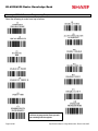
Free Key Layouts
Key Location No. Reading
1. Procedure:
1) Place the SRV key to the SRV-Mode position
2) Enter the following sequence:
951
@
CASH
2. Print Out:
Specifications subject to change without notice: Revision date 10/07
Page 37 of 266
ER-A520/A530 Dealer Knowledge Book
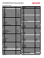
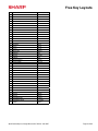
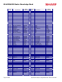
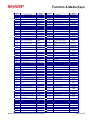
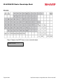
Function Key ListKey
No.
FUNCTION
KEY TEXT (8 Char.)
No.
FUNCTION
KEY TEXT (8 Char.)
1
0 KEY
0
KEY
47
REFUND
RFND
2
1 KEY
1
KEY
48
RETURN
RETURN
3
2 KEY
2
KEY
49
%1
%1
4
3 KEY
3
KEY
50
%2
%2
5
4 KEY
4
KEY
51
%3
%3
6
5 KEY
5
KEY
52
%4
%4
7
6 KEY
6
KEY
53
%5
%5
8
7 KEY
7
KEY
54
(-) 1
(-) 1
9
8 KEY
8
KEY
55
(-) 2
(-) 2
10
9 KEY
9
KEY
56
(-) 3
(-) 3
KEY
57
(-) 4
(-) 4
11
00 KEY
00
12
000KEY
00 0K EY
58
(-) 5
(-) 5
13
DECIMAL POINT
.
59
TAX
TAX
14
CLEAR
C L EAR
60
COVER COUNT
CVCNT
15
@/FOR
@/FOR
61
AUTO
AUTO
16
SUB TOTAL
SBTL
62
AUTO2
AUTO2
17
CA/AT
C A/ AT
63
AUTO3
AUTO3
18
MERCHANDISE SUB-TOTAL
MDS
ST
64
AUTO4
AUTO4
19
TRAY SUB-TOTAL
TRY
ST
65
AUTO5
AUTO5
20
GASOLINE SALES SUB-TOTAL
GA S ST
66
AUTO6
AUTO6
21
NON ADD/TIME
#/TM
67
AUTO7
AUTO7
22
NO SALE
NS
68
AUTO8
AUTO8
23
PLU/SUB/UPC
PLU/SB
69
AUTO9
AUTO9
24
REFUND TYPE OF SALES
RF
70
AUT010
AUTO10
25
LEVEL SHIFT#
LEVEL#
71
CASH2
CA2
26
LEVEL1
L1
72
CASH3
CA3
27
LEVEL2
L2
73
CASH4
CA4
28
LEVEL3
L3
29
LEVEL4
L4
30
LEVEL5
L5
31
PRICE SHIFT #
P.
32
PRICE1
P1
33
PRICE2
P2
34
PRICE3
P3
35
PRICE4
P4
36
PRICE5
P5
KEY
SAL
SFT#
37
PRICE6
P6
38
TAX1 SHIFT
TAX1SF
39
TAX2 SHIFT
TAX2SF
40
TAX3 SHIFT
TAX3SF
41
TAX4 SHIFT
TAX4SF
42
FS SHIFT
FS
SFT
74
CASH5
CA5
75
CHECK
CHECK
76
CHECK2
CHECK2
77
CHECK3
CHECK3
78
CHECK4
CHECK4
79
CHECK5
CHECK5
80
CHARGE1
CH1
81
CHARGE2
CH2
82
CHARGE3
CH3
83
CHARGE4
CH4
84
CHARGE5
CH5
85
CHARGE6
CH6
86
CHARGE7
CH7
87
CHARGE8
CH8
88
CHARGE9
CH9
89
CURRENCY CONVERSION1
CONV1
43
VALIDATION PRINT
PRINT
44
SLIP (BILL)
SLIP
45
COPY/AFTER TRANSACTION RECEIPT
RCP T
90
CURRENCY CONVERSION2
CONV2
V OID
91
CURRENCY CONVERSION3
CONV3
46
VOID
Page 38 of 266
Specifications subject to change without notice: Revision date 10/07
Free Key Layouts
No.
FUNCTION
KEY TEXT (8 Char.)
92
CURRENCY CONVERSION4
CONV4
93
GLU/PBLU/PB
PBAL/PB
94
NEW CHECK/PB
N. C. /CB
95
SERVICE
SRVC
96
FINAL
FINAL
97
DEPOSIT
DEPO
98
DEPOSIT REFUND
DEP. RF
99
FS TEND
FSTEND
100
RECEIVED ON ACCOUNT
RA
101
RECEIVED ON ACCOUNT2
RA 2
102
PAID OUT
PO
103
PAID OUT2
PO 2
104
SERVER NUMBER
SRV#
105
BIRTHDAY
BIRTH
106
DEPT#
DEPT#
107
SCALE
SCALE
108
OPEN TARE
OPN TR
109
AMOUNT
AMT
110
REPEAT
REPEAT
111
INQUIRE
INQ
112
NO DELETE (UPC)
NO DEL
113
PRICE CHANGE
PR CHG
114
REMOTE PRINTER SEND
RP SND
115
CHARGE TIP
CH TIP
116
CASH TIP
CA TIP
117
TIP PAID
TIP PD
118
GRATUITY EXEMPT
GRT EX
119
EDIT TIP
ED TIP
120
BILL TRANSFER
B. T.
121
BILL SEPARATE
B. S.
122
TRANS OUT
TR OUT
123
TRANS IN
TR IN
124
GLU RECALL
GLU RC
125
WASTE MODE
WASTE
126
EAT IN1
EATIN1
127
EAT IN2
EATIN2
128
EAT IN3
EATIN3
129
CONDIMENT NEXT
C. NEXT
130
CONDIMENT CANCEL
C. CANCEL
999
INHIBIT
INHIBIT
Specifications subject to change without notice: Revision date 10/07
Page 39 of 266
Section-3: File Allocation
File Allocation
Memory Allocation
.
971
XX
@/FOR
@/FOR
YYYYY
(Type 0,1)
@/FOR
CA/AT
ZZZZZ
(Type 2)
Procedure:
Enter the SRV-mode as previously outlined.
Enter 971 ൺ [ . ]
ཱ Depress [@/FOR] key.
ི Enter the File Group number you want to allocate.
ཱི Depress [@/FOR] key.
ུ Enter the value for the File Group.
ཱུ If it is File Group type 2, depress [@/FOR] key, enter the number for data.
ྲྀ Depress the [CA/AT] key.
File Group Table
Group
No.
FILE NAME
TYPE
File table No. (Create, Change the number of records or Erase/Change the number of records or Erase)
1
Dept
1
01, 02, 03, 05, 06
2
Dept TEXT (8)
0
03
3
Dept TEXT (16)
0
04
4
PLU/UPC
1
08, 09, 10, 12, 18, 20, 22
5
PLU/UPC PRICE 1
0
10, 20, 22,
/21, 23
6
PLU/UPC PRICE 1-6
0
11, 24, 26,
/25, 27
7
PLU/UPC TEXT1 (8)
0
12
8
PLU/UPC TEXT1 (16)
0
13
9
PLU/UPC KP TEXT1 (12)
0
14
10
PLU/UPC TEXT1-6 (8)
0
15
11
PLU/UPC TEXT1-6 (16)
0
16
12
PLU/UPC KP TEXT1-6 (12)
0
17
13
PLU/UPC stock
0
19
14
DYNAMIC UPC
1
28, 29, 30, 33, 34, 38, 39, 41
15
DYNAMIC UPC PRICE 1
0
30, 39, 41,
/40, 42
16
DYNAMIC UPC PRICE 1-6
0
31, 43, 45,
/44, 46
17
DYNAMIC UPC TEXT1 (8)
0
32
18
DYNAMIC UPC TEXT1 (16)
0
33
19
DYNAMIC UPC KP TEXT1 (12)
0
34
20
DYNAMIC UPC TEXT1-6 (8)
0
35
21
DYNAMIC UPC TEXT1-6 (16)
0
36
22
DYNAMIC UPC KP TEXT1-6 (12)
0
37
23
UPC PGM PICK UP
1
47
24
DYNAMIC UPC PGM PICK UP
1
48
25
UPC X/Z PICK UP
1
49
Specifications subject to change without notice: Revision date 10/07
Page 43 of 266
ER-A520/A530 Dealer Knowledge Book
Group
No.
26
FILE NAME
TYPE
File table No. (Create, Change the number of records or Erase/Change the number of records or Erase)
DYNAMIC UPC X/Z PICK UP
1
50
27
Link PLU
1
51
28
Set PLU
1
52
29
Condiment table
1
53, 79
30
Mix&Match Table
1
54, 55
31
SERVER
1
59, 60, 61, 62, 63,
/64, 74, 81, 82
/79, 73, 74, 81, 82
32
Reg buffer
1
69, 70, 71, 72,
33
Overlapped Server
0
74, 81, 82
34
GLU/PBLU
2
75, 80
35
Closed GLU
1
76, 77
36
AUTO GLU Generate code
1
78
37
KP BUFFER
0
73
38
BS/BT buffer
0
72
39
Term Dept
0
07
40
Term PLU/UPC
0
21, 23
41
Term Transaction
0
58
42
Term SERVER
0
64
43
Term DYNAMIC UPC
0
40, 42
44
All of term file
0
07, 21, 23, 40, 42, 58, 64
Type 0: Create/Erase only
Type 1: Create/Erase and Increase/Decrease the number of records.
Type 2: Create/Erase and Increase/Decrease the number of records for label and data individually.
Note: All memories are shared in the fixed RAM area.
Page 44 of 266
Specifications subject to change without notice: Revision date 10/07
File Allocation
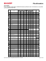
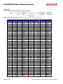
FILE TABLE
Note: This table can be used to calculate the memory allocation size. Its information is not printed
on FILE READING REPORT.
RECORD
File
No.
NAME
BLOCK
Label
Size
Data Size
3
8
1
0
3
1
0
8
1
0
16
(MA
X)
1
(MRS)
(MAX)
DEPT PRESET
20
99
02
PRICE
20
99
(1)
1
03
TEXT (8 chara)
0
99
(1)
1
04
TEXT (16 chara)
20
99
(1)
1
05
CVM CHARACTER
20
99
(1)
1
1
0
1
06
DAILY
20
99
(1)
1
1
0
13
07
TERM
20
99
(1)
1
1
0
13
08
PLU/UPC PRESET
1000
*****
1
1
9
15
09
FLAG
1000
*****
(8)
1
1
0
3
10
PRICE1
1000
*****
(8)
1
1
0
3
01
#1
(MRS
)
1
#2
11
PRICE1-6
0
*****
(8)
1
1
0
18
12
TEXT1 (8 chara)
0
*****
(8)
1
1
0
8
13
TEXT1 (16 chara)
1000
*****
(8)
1
1
0
16
14
KP TEXT1 (12 chara)
1000
*****
(8)
1
1
0
12
15
TEXT1-6 (8 chara)
0
*****
(8)
1
1
0
48
16
TEXT1-6 (16 chara)
0
*****
(8)
1
1
0
96
17
KP TEXT1-6 (12 chara)
18
CVM CHARACTER
19
STOCK
20
21
22
0
*****
(8)
1
1
0
72
1000
*****
(8)
1
1
0
1
0
*****
(8)
1
1
0
4
DAILY (Price1)
1000
*****
(8)
1
1
0
9
TERM (Price1)
0
*****
(8)
1
1
0
9
WASTE DAILY (Price1)
1000
*****
(8)
1
1
0
9
23
WASTE TERM (Price1)
0
*****
(8)
1
1
0
9
24
DAILY (Price1-6)
0
*****
(8)
6
6
0
9
25
TERM (Price1-6)
0
*****
(8)
6
6
0
9
26
WASTE DAILY (Price1-6)
0
*****
(8)
6
6
0
9
27
WASTE TERM (Price1-6)
0
*****
(8)
6
6
0
9
28
DYNAMIC UPC PRESET
0
*****
1
1
9
13
29
FLAG
0
*****
(28)
1
1
0
3
30
PRICE1
0
*****
(28)
1
1
0
3
31
PRICE1-6
0
*****
(28)
1
1
0
18
32
TEXT1 (8 chara)
0
*****
(28)
1
1
0
8
33
TEXT1 (16 chara)
0
*****
(28)
1
1
0
16
34
KP TEXT1 (12 chara)
0
*****
(28)
1
1
0
12
35
TEXT1-6 (8 chara)
0
*****
(28)
1
1
0
48
36
TEXT1-6 (16 chara)
0
*****
(28)
1
1
0
96
37
KP TEXT1-6 (12 chara)
0
*****
(28)
1
1
0
72
38
CVM CHARACTER
0
*****
(28)
1
1
0
1
39
DAILY (Price1)
0
*****
(28)
1
1
0
9
Specifications subject to change without notice: Revision date 10/07
Page 45 of 266
ER-A520/A530 Dealer Knowledge Book
RECORD
File
No.
Page 46 of 266
NAME
BLOCK
Data Size
40
TERM (Price1)
0
*****
(28)
0
9
41
WASTE DAILY (Price1)
0
*****
(28)
1
1
0
9
42
WASTE TERM (Price1)
0
*****
(28)
1
1
0
9
43
DAILY (Price1-6)
0
*****
(28)
6
6
0
9
44
TERM (Price1-6)
0
*****
(28)
6
6
0
9
45
WASTE DAILY (Price1-6)
0
*****
(28)
6
6
0
9
46
WASTE TERM (Price1-6)
0
*****
(28)
6
6
0
9
47
UPC PGM PICK UP
100
100
1
1
9
0
48
DYNAMIC UPC PGM
PICK UP
0
100
1
1
9
0
49
UPC X/Z PICK UP
100
100
1
1
9
0
50
DYNAMIC UPC X/Z PICK
UP
0
100
1
1
9
0
51
LINK PLU
10
*****
1
1
9
35
52
SET PLU
10
*****
1
1
9
70
53
Condiment Table
10
99
1
1
3
107
54
MIX & MATCH TABLE
10
99
1
1
3
4
55
MIX & MATCH SOLD
10
99
1
1
0
5
56
TRANSACTION LABEL
169
169
1
1
4
0
57
DAILY
169
169
(56)
1
1
0
9
58
TERM
169
169
(56)
1
1
0
9
59
SERVER PRESET
20
20
0
1
1
3
10
60
FLAG
20
20
(59)
1
1
0
1
(MAX)
#1
(54)
(MA
X)
1
Label
Size
(MRS
)
1
(MRS)
#2
61
TEXT
20
20
(59)
1
1
0
8
62
SERVER TRNS. LABEL
113
113
0
20
20
(59)
4
0
63
DAILY
113
113
(62)
20
20
(59)
0
9
64
TERM
113
113
(62)
20
20
(59)
0
9
65
RESET SERVER LABEL
113
113
0
1
1
4
0
66
TOTAL
113
113
(65)
1
1
0
9
67
TOTAL SERVER LABEL
113
113
0
1
1
4
0
68
TOTAL
113
113
(67)
1
1
0
9
69
REG BUFFER
250
250
0
1
1
0
48
70
(Reserved)
0
0
0
1
1
0
48
71
GLU/PBLU BUFFER
250
250
0
1
1
0
48
72
B.T. BUFFER
250
250
0
1
1
0
48
73
KP BUFFER
0
250
0
1
1
0
52
74
OVERLAPPED SERVER
0
250
0
0
20
0
48
75
GLU/PBLU
10-1000
*********
0
1
1
4
43
76
CLOSED GLU
0
*****
0
1
1
4
146
77
CLOSED GLU AMOUNT
0
*****
(76)
1
1
0
125
78
AUTO GLU Generate Code
11
11
0
1
1
0
2
79
CONDIMENT EDIT
BUFFER
250
250
0
1
1
0
48
80
OPEN GLU BUFFER
250
250
0
1
1
6
10
(59)
Specifications subject to change without notice: Revision date 10/07
File Allocation
File
No.
81
82
83
RECORD
NAME
OVERLAPPED
GLU/PBLU BUFFER
OVERLAPPED
MIX&MATCH BUFFER
FUNCTION TEXT
BLOCK
Label
Size
Data Size
(59)
0
48
(59)
0
5
4
8
(MRS)
(MAX)
#1
(MRS
)
(MA
X)
#2
0
250
0
0
20
0
250
0
0
20
289
289
0
1
1
(#1): Same as the number of record of table no.
(#2): Same as the number of block of table no.
Specifications subject to change without notice: Revision date 10/07
Page 47 of 266
ER-A520/A530 Dealer Knowledge Book
NOTES
Page 48 of 266
Specifications subject to change without notice: Revision date 10/07
Section-4: PERIPHERALS
PERIPHERALS
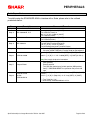
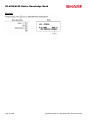
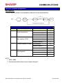
Overview – Cable & Communications Specifications
RS-232 connections are simple, universal and a supported data interface for the ER-A520 and
ER-A530 model ECRs. The standards for communications of 256kbps or less and line lengths of
15m (50 ft) or less will depend on the length and quality of the cable.
1. Specifications:
(1) Cable: 24 – 28 AWG, Shielded, twisted pair – (refer to the chart on the next page)
(2) Connector: D – Sub 9 pin (female type) connector.
(3) Baud Rate: (Please refer to each peripheral’s section)
COM-1
COM-2
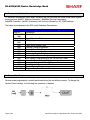
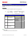
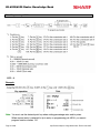
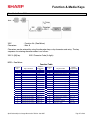
2. Pin Outs:
(Please refer to each peripheral’s section.)
Specifications subject to change without notice: Revision date 10/07
Page 51 of 266
ER-A520/A530 Dealer Knowledge Book
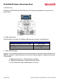
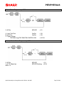
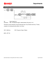
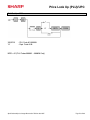
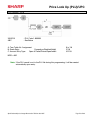
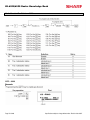
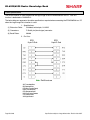
3. ECR Pin Outs:
The DB-9 of the ER-A520 and ER-A530 follows EIA computer specifications for its pin outs as
shown below:
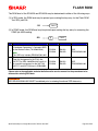
4. Belden Cable Chart:
The chart below is the specs for a Belden cable that can be used for communications.
RS232 Serial Cable
Maximum Distance from POS to Printer
Type Cable
Wire Gauge
Belden Number
50 ft. or less
Twisted Pair
24 AWG / Shielded
9540
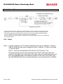
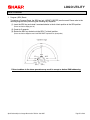
5. Cable Chart/Distances:
Typically, the recommended cabling distance length will be less than 25 feet when the data rate is
9600 bps or greater. If transmission errors occur, follow these procedures to determine the cause
of the problem:
1) Reduce the baud rate – when the preset is available.
2) Reduce the cable length – when the baud rate is fixed.
3) Use a cable with a lower capacitance per foot rating.
Page 52 of 266
Specifications subject to change without notice: Revision date 10/07
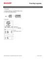
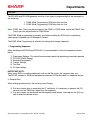
PERIPHERALS
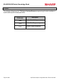
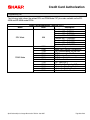
Section – 1: Coin Dispenser
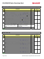
The following table shows the related PGM-Mode Job#s available for the ER-A520 and ER-A530
model ECRs when the Coin Dispenser is connected.
Scale
Mode
Job#
2690
Description
Channel Assignment
PGM-Mode
2510
Cashier Drawer Assignment
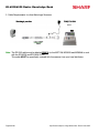
Note: The Telequip Transact coin dispenser (sales item ER-COIN) includes the necessary
connection cable as standard equipment.
Specifications subject to change without notice: Revision date 10/07
Page 53 of 266
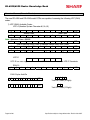
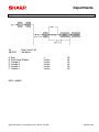
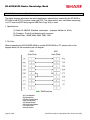
ER-A520/A530 Dealer Knowledge Book
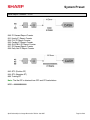
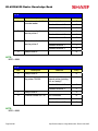
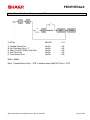
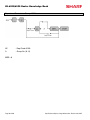
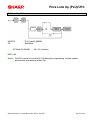
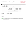
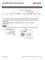
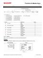
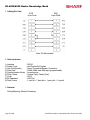
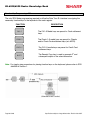
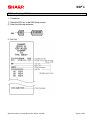
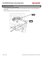
1. Cabling Pin Outs:
UP-3301
D-SUB99 (Female)
(Female)
D-SUB
ER-A520/A530
TeleQuip Coin
FG
1
1
RXD
2
3
TXD
TXD
3
2
RXD
DTR
4
4
S.G
5
5
DSR
6
RTS
7
CTS
8
CI
9
GND
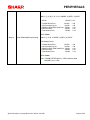
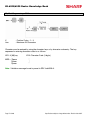
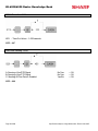
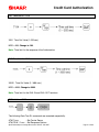
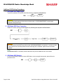
2. Data Transmission:
-
7 bits ASCII code
One Start bit
Even Parity
One Stop bit
Baud Rate: 9600 bps (fixed)
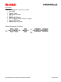
3. Protocol
(ECR)
(Coin)
EOT
“C”
<STX>XX<ETX><CC>
STATUS
ACK
or
STATUS
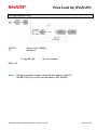
NAK
XX: Ten’s + ones
CC: Cents
Page 54 of 266
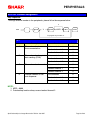
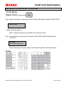
Specifications subject to change without notice: Revision date 10/07
PERIPHERALS
RS-232C Channel Assignment
ER-A520/530 is equipped with two RS-232C interfaces. If you use the communication functions,
the channel number of each RS-232C interface must be programmed by using the following
procedure.
Key Sequence:
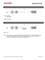
To assign channel number to the peripherals, please follow the sequence below:
0
2690
.
@/FOR
X
ABCD
@/FOR
SBTL
CA/AT
To program any function no.
X=1
Item
A
B
C
D
Description
Channel number for online communication
Channel number for print
data sending (CVM)
Channel number for scale
Channel number for the
coin dispenser
Selection
Entry
Not connected
0
Standard channel 1
1
Standard channel 2
2
Not connected
0
Standard channel 1
1
Standard channel 2
2
Not connected
0
Standard channel 1
1
Standard channel 2
2
Not connected
0
Standard channel 1
1
Standard channel 2
2
NOTE:
1. MRS = 0000
2. Data backup function always uses standard channel 2.
Specifications subject to change without notice: Revision date 10/07
Page 55 of 266
ER-A520/A530 Dealer Knowledge Book
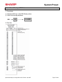
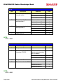
X=2
Item
A
B
C
D
Description
Channel number for the
barcode reader
Channel number the
remote printer 1
Channel number for the
remote printer 2
Selection
Entry
Not connected
0
Standard channel 1
1
Standard channel 2
2
Not connected
0
Standard channel 1
1
Standard channel 2
2
Not connected
0
Standard channel 1
1
Standard channel 2
2
Always enter 0
0
NOTE:
MRS = 0000
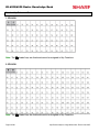
X=3
Item
Description
A
Always enter 0
B
Channel number for the
slip printer TM-295
C
Always enter 0
D
Channel number for CAT
Selection
Entry
0
Not connected for
internal printer (printing
bills on receipt)
0
Standard channel 1
1
Standard channel 2
2
0
Not connected
0
Standard channel 1
1
Standard channel 2
2
NOTE:
MRS = 0000
Page 56 of 266
Specifications subject to change without notice: Revision date 10/07
PERIPHERALS
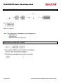
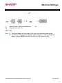
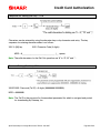
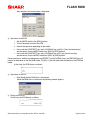
Procedure:
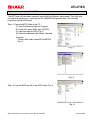
Enter the PGM2-Mode as previously outlined
1. Enter 2690
2. Depress [.] key
3. Depress [@/FOR] key
4. Enter 1
5. Depress [@/FOR] key
6. Enter assigned channel numbers ( 4 digits)
7. Depress [SBTL] key
8. Depress the [CA/AT] key
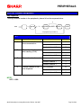
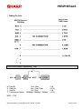
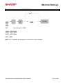
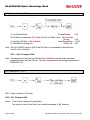
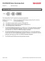
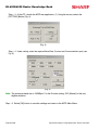
Channel Assignment for COIN DISPENSER:
Quick Steps – Coin Dispenser
To quickly setup the ER-A520/ER-A530 to interface with a coin dispenser, please refer to the
outlined procedures below:
No.
Description
Step–1
Connect the Coin Dispenser
Step–2
PGM Job#2690
Step–3
Program Reset
Step–4
PGM Job#2510
Comments/Procedure
CH–1 or CH–2
2690 Æ [.] Æ [@] Æ 1 Æ @ Æ 0001 [SBTL] Æ [CA/AT] for CH–1)
or
2690 Æ [.] Æ [@] Æ 1 Æ @ Æ 0002 [SBTL] Æ [CA/AT] for CH–2)
Note: Must match the physical connection
• Place the SRV-Key counter-clockwise to 6 o’clock position
(SRV’ position)
• Count 5 seconds
• Turn SRV-Key clockwise to 7o’clock position (SRV position)
• Verify”***PROGRAM RESET has printed on the journal-side
tape.
Verify that the Cashiers have a valid Drawer Assignment (1 or 2)
Specifications subject to change without notice: Revision date 10/07
Page 57 of 266
ER-A520/A530 Dealer Knowledge Book
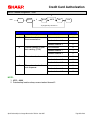
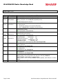
Section–2: Scale
The following table shows the related SRV and PGM-Mode Job#s available for the ER-A520 and
ER-A530 model ECRs when the Scale is connected.
Mode
Scale
Job#
903–B
903–C
906–D
918–B
Description
Symbol of Scale Entry
Unit of Weight for Scale Entries
Fractional Quantities Entries
Fractional Entries for Non-Scalable
Dept./PLU Items
SRV-Mode
[SCALE] – Function #107
950
(OPEN TARE] – Function #108
PGM-Mode
Page 58 of 266
2690
2110
2210
2231
2618
Channel Assignment
Dept. Function Programming
PLU Function Programming
PLU Function Range Programming
Scale Tare Table Programming
Specifications subject to change without notice: Revision date 10/07
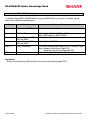
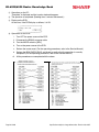
PERIPHERALS
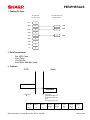
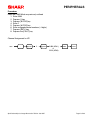
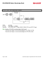
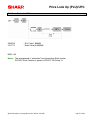
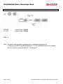
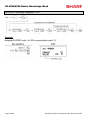
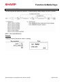
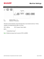
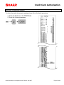
1, Cabling Pin Outs:
Avery/NCI/Weightronix
D-SUB 9 (Female)
ER-A520/A530
UP-3301
D-SUB 99 (Female)
(Female)
D-SUB
FG
1
RXD
2
3
TXD
TXD
3
2
RXD
DTR
4
S.G
5
5
GND
DSR
6
RTS
7
CTS
8
CI
9
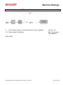
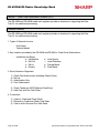
2. Data Transmission:
-
Bits ASCII Code
Even Parity
One Stop Bit
Baud Rate: 9600 bps (fixed)
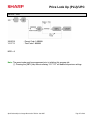
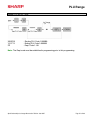
3. Protocol:
(ECR)
(Scale)
COMMAND
RESPONSE
<Command>
W
<Response>
<STX>0XX.XX<CR>;LB
<STX>0XX.XX<CR>;KG
(Error)
<STX>Status byte><CR>
B7
Parity Bit
B6
Always
B5
Net Wt.
(Even)
=1
=1
Specifications subject to change without notice: Revision date 10/07
B4
Center
Of Zero
=1
B3
Outside
Of Zero
=1
B2
Under
Zero
=1
B1
Out Of
Range
=1
B0
Motion
=1
Page 59 of 266
ER-A520/A530 Dealer Knowledge Book
RS-232C Channel Assignment
Key Sequence:
To assign channel number to the peripherals, please follow the sequence below:
0
2690
.
@/FOR
X
ABCD
@/FOR
SBTL
CA/AT
To program any function no.
X=1
Item
A
B
C
D
Description
Channel number for online communication
Channel number for print
data sending (CVM)
Channel number for scale
Channel number for the
coin dispenser
Selection
Entry
Not connected
0
Standard channel 1
1
Standard channel 2
2
Not connected
0
Standard channel 1
1
Standard channel 2
2
Not connected
0
Standard channel 1
1
Standard channel 2
2
Not connected
0
Standard channel 1
1
Standard channel 2
2
NOTE:
1. MRS = 0000
2. Data backup function always uses standard channel 2.
Page 60 of 266
Specifications subject to change without notice: Revision date 10/07
PERIPHERALS
X=2
Item
A
B
C
D
Description
Channel number for the
barcode reader
Channel number the
remote printer 1
Channel number for the
remote printer 2
Selection
Entry
Not connected
0
Standard channel 1
1
Standard channel 2
2
Not connected
0
Standard channel 1
1
Standard channel 2
2
Not connected
0
Standard channel 1
1
Standard channel 2
2
Always enter 0
0
NOTE:
MRS = 0000
X=3
Item
Description
A
Always enter 0
B
Channel number for the
slip printer TM-295
C
Always enter 0
D
Channel number for CAT
Selection
Entry
0
Not connected for
internal printer (printing
bills on receipt)
0
Standard channel 1
1
Standard channel 2
2
0
Not connected
0
Standard channel 1
1
Standard channel 2
2
NOTE:
MRS = 0000
Specifications subject to change without notice: Revision date 10/07
Page 61 of 266
ER-A520/A530 Dealer Knowledge Book
Procedure:
Enter the PGM2-Mode as previously outlined
1. Enter 2690
2. Depress [.] key
3. Depress [@/FOR] key
4. Enter 1
5. Depress [@/FOR] key
6. Enter assigned channel numbers ( 4 digits)
7. Depress [SBTL] key
8. Depress the [CA/AT] key
Channel Assignment for SCALE:
2690
Page 62 of 266
.
@/FOR
1
@/FOR
0010
or
0020
SBTL
CA/AT
Specifications subject to change without notice: Revision date 10/07
PERIPHERALS
Quick Steps – Scale
To quickly setup the ER-A520/ER-A530 to interface with a Scale, please refer to the outlined
procedures below:
No.
Description
Step–1
Connect the Scale
Step–2
SRV Job#903-B, C, D
Step–3
SRV Job#906-D
Step–4
SRV Job#918
Step-5
SRV Job#950
Step-6
PGM Job #2690
Step-7
Program Reset
Step-8
PGM Job #2110
-and/orPGM Job#2210
Comments/Procedure
CH–1 or CH–2
903 Æ [.] Æ [@] Æ x030 Æ [CA/AT]
(For 3 Decimal Places) or
903 Æ [.] Æ [@] Æ x020 Æ [CA/AT]
(For 2 Decimal Places)
906 Æ [.] Æ [@] Æ xxx1 Æ [CA/AT]
(For Fractional Entries)
918 Æ [.] Æ [@] Æ x0xx Æ [CA/AT]
(For Non-Scale Fractional Entries) or
918 Æ [.] Æ [@] Æ x1xx Æ [CA/AT]
(For Disallowing Non-Scale Fractional Entries)
• Place the [SCALE] Key (Function #107) on the keyboard
• Place the [OPEN TARE] Key (Function #108) on the keyboard
2690 Æ [.] Æ [@] Æ 1 Æ @ Æ 0010 [SBTL] Æ [CA/AT] for CH–1)
or
2690 Æ [.] Æ [@] Æ 1 Æ @ Æ 0020 [SBTL] Æ [CA/AT] for CH–2)
Note: Must match the physical connection
• Place the SRV-Key counter-clockwise to 6 o’clock position
(SRV’ position)
• Count 5 seconds
• Turn SRV-Key clockwise to 7o’clock position (SRV position)
• Verify”***PROGRAM RESET has printed on the journal-side
tape.
2110 Æ [.] Æ [@] Æ (Dept. No.) Æ @ Æ xyzxxx [SBTL] Æ [CA/AT]
–and/or2210 Æ [.] Æ [@] Æ (Dept. No.) Æ @ Æ xyz [SBTL] Æ [CA/AT]
Y = Tare Table No. (1–9)
Z = Scale Comp. /Enabled/Inhibited = 2/1/0
Specifications subject to change without notice: Revision date 10/07
Page 63 of 266
ER-A520/A530 Dealer Knowledge Book
Section–3: Slip Printer
The following table shows the related SRV and PGM-Mode Job#s available for the ER-A520 and
ER-A530 ECRs when the Slip Printer is connected.
Slip Printer
Mode
Job#
913–B
920-A
921-C
928–A
928–B
SRV-Mode
928–C
928–D
950
PGM-Mode
Page 64 of 266
2690
2320
2615
2616 – 1, 2, 7, 8
Description
Escape Compulsory SLIP & Validation
Combine like items for GLU items printed a bill
Bill Printing Method
Printing of Slip Logo
Val. Message Printing on Slip
Header Line Printing on Slip when Reorder Printing
Print PLU Items on Slip when $0.00
Set PLU Items Print on Slip
PB/NBAL Prints on Slip
Slip Print Compulsion System
[PRINT]–Function #43
[SLIP]–Function #44
Channel Assignment
Media Key Function Programming
Validation Limitation Programming
Validation for Refund, PO, RA, Item, (-), and Item Printing
for PBLU Sale on Slip Printer
Specifications subject to change without notice: Revision date 10/07
PERIPHERALS
Specifications subject to change without notice: Revision date 10/07
Page 65 of 266
ER-A520/A530 Dealer Knowledge Book
1. Cabling Pin Outs:
ECR
9-Pin D–Sub
SLIP PRINTER
25-Pin D–Sub
2. Data Transmission:
-
8 Bits ASCII Code
No Start Bit
Non Parity
1 Stop Bit
Baud Rate: 9600 bps (fixed)
*Handshaking: DTR/DSR Control
Page 66 of 266
Specifications subject to change without notice: Revision date 10/07
PERIPHERALS
TM-U295 Switch–1Settings:
ROM Version 1.08
On
Switch
Contents
SW1-1
SW1-2
SW1-3
SW1-4
SW1-5
SW1-6
SW1-7
SW1-8
SW1-9
SW-10
Data Receive Buffer
Receive Buffer Capacity
Handshaking
Data Word length
Parity Check
Parity selection
Baud Rate Selection
Baud Rate Selection
DSR (#6) Reset
Init (#25) Reset
Ignored
35 bytes
XON/XOFF
7 bits
With Parity
Even Parity
(*1)
(*1)
Effective
Effective
Off
Prints “?”
512 Kbytes
DTR/DSR
8 bits
Without Parity
Odd Parity
Invalid
Invalid
Setting
OFF
OFF
OFF
OFF
OFF
OFF
OFF
OFF
OFF
ON
(*1): SW1-7, 1-8 Definitions
Rate
SW1-7
SW1-8
1200 bps
2400 bps
4800 bps
9600 bps
ON
OFF
ON
OFF
ON
ON
OFF
OFF
Specifications subject to change without notice: Revision date 10/07
Page 67 of 266
ER-A520/A530 Dealer Knowledge Book
RS-232C Channel Assignment
Key Sequence:
To assign channel number to the peripherals, please follow the sequence below:
0
2690
.
@/FOR
X
ABCD
@/FOR
SBTL
CA/AT
To program any function no.
X=1
Item
A
B
C
D
Description
Channel number for online communication
Channel number for print
data sending (CVM)
Channel number for scale
Channel number for the
coin dispenser
Selection
Entry
Not connected
0
Standard channel 1
1
Standard channel 2
2
Not connected
0
Standard channel 1
1
Standard channel 2
2
Not connected
0
Standard channel 1
1
Standard channel 2
2
Not connected
0
Standard channel 1
1
Standard channel 2
2
NOTE:
1. MRS = 0000
2. Data backup function always uses standard channel 2.
Page 68 of 266
Specifications subject to change without notice: Revision date 10/07
PERIPHERALS
X=2
Item
A
B
C
D
Description
Channel number for the
barcode reader
Channel number the
remote printer 1
Channel number for the
remote printer 2
Selection
Entry
Not connected
0
Standard channel 1
1
Standard channel 2
2
Not connected
0
Standard channel 1
1
Standard channel 2
2
Not connected
0
Standard channel 1
1
Standard channel 2
2
Always enter 0
0
NOTE:
MRS = 0000
X=3
Item
Description
A
Always enter 0
B
Channel number for the
slip printer TM-295
C
Always enter 0
D
Channel number for CAT
Selection
Entry
0
Not connected for
internal printer (printing
bills on receipt)
0
Standard channel 1
1
Standard channel 2
2
0
Not connected
0
Standard channel 1
1
Standard channel 2
2
NOTE:
MRS = 0000
Specifications subject to change without notice: Revision date 10/07
Page 69 of 266
ER-A520/A530 Dealer Knowledge Book
Procedure:
Enter the PGM2-Mode as previously outlined
1. Enter 2690
2. Depress [.] key
3. Depress [@/FOR] key
4. Enter 3
5. Depress [@/FOR] key
6. Enter assigned channel numbers ( 4 digits)
7. Depress [SBTL] key
8. Depress the [CA/AT] key
Channel Assignment for SLIP PRINTER:
Page 70 of 266
Specifications subject to change without notice: Revision date 10/07
PERIPHERALS
Quick Steps – Slip Printer
To quickly setup the ER-A520/ER-A530 to interface with an Epson TM-U295 Slip Printer, please
refer to the outlined procedures below:
No.
Description
Step–1
Connect the Slip Printer
Step–2
SRV Job#913-B
Step–3
SRV Job#928- A, B, C, D
Step-4
SRV Job#950
Step-5
PGM Job #2690
Step-6
Program Reset
Step-7
PGM Job #2615
Step-8
PGM Job #2616 #1
Step-9
PGM Job #2616 #2
Step-10
PGM Job #2616 #7
Step-11
PGM Job #2616 #8
Comments/Procedures
CH–1 or CH–2
913 Æ [.] Æ [@] Æ x1xx Æ [CA/AT]
(For Escaping Compulsory Slip or Validation) or
913 Æ [.] Æ [@] Æ x0xx Æ [CA/AT]
(For No Escape of Compulsory Slip or Validation)
928 Æ [.] Æ [@] Æ ABCD Æ [CA/AT]
A: Slip Logo Text Prints
Yes/No = 1/0
B: VP Message Prints on Slip
Yes/No = 2/0
B: C: Header Line on Slip Prints Reorder
No/Yes = 1/0
C: Prints $0.00 PLU Items on Slip
No/Yes = 4/0
C: Prints PLU Text of Set PLU Links on Slip
No/Yes = 2/0
D: Print the PB/NBAL on Slip
No/Yes = 4/0
D: Compulsory Slip System PBLU Only/Every Trans/By Media
Yes/No = 2/1/0
• Place the [SLIP] Key (Function #44) on the keyboard
• Place the [PRINT (Validation)] Key (Function #43) on the
keyboard
2690 Æ [.] Æ [@] Æ 3 Æ @ Æ 0100 [SBTL] Æ [CA/AT] for CH–1)
or
2690 Æ [.] Æ [@] Æ 3 Æ @ Æ 0200 [SBTL] Æ [CA/AT] for CH–2)
Note: Must match the physical connection
• Place the SRV-Key counter-clockwise to 6 o’clock position
(SRV’ position)
• Count 5 seconds
• Turn SRV-Key clockwise to 7o’clock position (SRV position)
• Verify”***PROGRAM RESET has printed on the journal-side
tape.
2615 Æ [.] Æ [@] Æ VVXXAB Æ [SBTL] Æ [CA/AT]VV: Initial Line Feed
XX: Max Slip Line No.
A: No. of Times for Validation when set for Compulsory = 0–9
B: No. Line Feed after Tray SBTL key is depressed = 0–9
2616 Æ [.] Æ [@] Æ 1Æ ABCDEFGH Æ [SBTL] Æ [CA/AT]H: Validation for Refund Entries Compulsory/NOT= 1/0
2616 Æ [.] Æ [@] Æ 2Æ ABCDEFGH Æ [SBTL] Æ [CA/AT]G: Item Validation
Disable/Enable = 1/0
H: Validation printing for discount (-) entry Compulsory/NOT= 1/0
2616 Æ [.] Æ [@] Æ 7Æ ABCDEFGH Æ [SBTL] Æ [CA/AT]E: Item Printing within PBLU Sale on Slip Printer No/Yes = 1/0
2616 Æ [.] Æ [@] Æ 8Æ ABCDEFGH Æ [SBTL] Æ [CA/AT]E: Validation for Check Cashing Compulsory/NOT= 1/0
F: Validation for RA Items
Compulsory/NOT= 1/0
G: Validation for PO Items
Compulsory/NOT= 1/0
H: Validation for tip-in/tip-paid
Compulsory/NOT= 1/0
Specifications subject to change without notice: Revision date 10/07
Page 71 of 266
ER-A520/A530 Dealer Knowledge Book
Section–4: Remote Kitchen Printer
The following table shows the related SRV and PGM-Mode Job#s available for the ER-A520 and
ER-A530 ECRs when a Remote Printer is connected.
Mode
Remote Kitchen Printer
Job#
918–A
918–B
SRV-Mode
PGM-Mode
Page 72 of 266
Description
918–C
Output of Set PLU to KP
Red Color Print on KP when PLU/UPC’s are ZERO price
items
Like Items Consolidation on KP
918–C
Dept/PLU and UPC (EAN) Text Print on KP in Double
Size Character
926–A
Sending Direct VOID and Past Item VOID Data to the KP
926-B
929-A
Sending Refund Data to the KP
KP Print Format when Finalizing (Expediter Print Format)
950
[RP Send]–Function #114
971
971
# 9 KP Text 1 (12)/ #12 KP Text 1-6 (12) – Optional. If
not allocated the PLU description will be used.
#37 KP Buffer
2690
2692
3653
3654
3655
3656
2118
2218
2328
Channel Assignment
Kitchen Printer Programming
Back Up Kitchen Printer Programming
Kitchen Printer Name Programming
Kitchen Printer Print Format Programming
Chit Receipt Print Format Programming
Department KP Print Assignment Programming
PLU/UPC KP Print Assignment Programming
Media Key Print Assignment Programming
Specifications subject to change without notice: Revision date 10/07
PERIPHERALS
1. Cabling Pin Outs:
ECR
9-Pin D–Sub
EPSON PRINTER
25-Pin D–Sub
2. Data Transmission:
-
8 Bits ASCII Code
No Start Bit
Non Parity
1 Stop Bit
Baud Rate: 9600 bps (fixed)
*Handshaking: DTR/DSR Control
Specifications subject to change without notice: Revision date 10/07
Page 73 of 266
ER-A520/A530 Dealer Knowledge Book
Page 74 of 266
Specifications subject to change without notice: Revision date 10/07
PERIPHERALS
Kitchen Printer Programming - 2692
X: KP No.
KP2/KP1
A: Logo Text Print
Yes/No
B: Auto Cut
Yes/No
C: Type of Printer
TM-T88III+Logo/TM-T88III/TM-U230/TM-U220
= 2/1
= 1/0
= 1/0
= 3/2/1/0
Back Up Kitchen Printer Programming - 3653
X: KP No.
Y: 2nd KP (Back Up)
MRS = 0
Specifications subject to change without notice: Revision date 10/07
KP2/KP1
KP2/KP1/Nothing
= 2/1
=2/1/0
Page 75 of 266
ER-A520/A530 Dealer Knowledge Book
Kitchen Printer Name Programming - 3654
X: KP No.
KP2/KP1
= 2/1
KP Name: Maximum 12 Characters
Characters can be entered by using the character keys or by character code entry. The key
sequence for entering character codes is as follows:
XXX Æ [00] key
XXX: Character Code (3 digits)
MRS = Spaces
Page 76 of 266
Specifications subject to change without notice: Revision date 10/07
PERIPHERALS
Kitchen Printer Print Format Programming - 3655
X: KP No.
KP2/KP1
= 2/1
A: Taxable Status Print
B: Qty Print when Qty is “1”
C: Dept /PLU/UPC (EAN) Code Print
D: Unit Price Print
E: Total Amount Print
Yes/No
Yes/No
Yes/No
Yes/No
Yes/No
=1/0
=1/0
=1/0
=1/0
=1/0
MRS = 00000
Note: [Taxable Status Print] = “YES” is effective when [AMOUNT] Print = “YES”
Specifications subject to change without notice: Revision date 10/07
Page 77 of 266
ER-A520/A530 Dealer Knowledge Book
Chit Receipt Format Programming - 3656
A: Taxable Status Print
B: Qty Print when Qty is “1”
C: Dept /PLU/UPC (EAN) Code Print
D: Unit Price Print
E: Total Amount Print
Yes/No
Yes/No
Yes/No
Yes/No
Yes/No
=1/0
=1/0
=1/0
=1/0
=1/0
MRS = 00000
Note: [Taxable Status Print] = “YES” is effective when [AMOUNT] Print = “YES”
Page 78 of 266
Specifications subject to change without notice: Revision date 10/07
PERIPHERALS
RS-232C Channel Assignment
Key Sequence:
To assign channel number to the peripherals, please follow the sequence below:
0
2690
.
@/FOR
X
@/FOR
ABCD
SBTL
CA/AT
To program any function no.
X=1
Item
A
B
C
D
Description
Channel number for online communication
Channel number for print
data sending (CVM)
Channel number for scale
Channel number for the
coin dispenser
Selection
Entry
Not connected
0
Standard channel 1
1
Standard channel 2
2
Not connected
0
Standard channel 1
1
Standard channel 2
2
Not connected
0
Standard channel 1
1
Standard channel 2
2
Not connected
0
Standard channel 1
1
Standard channel 2
2
NOTE:
MRS = 0000
Specifications subject to change without notice: Revision date 10/07
Page 79 of 266
ER-A520/A530 Dealer Knowledge Book
X=2
Item
A
B
C
D
Description
Channel number for the
barcode reader
Channel number the
remote printer 1
Channel number for the
remote printer 2
Selection
Entry
Not connected
0
Standard channel 1
1
Standard channel 2
2
Not connected
0
Standard channel 1
1
Standard channel 2
2
Not connected
0
Standard channel 1
1
Standard channel 2
2
Always enter 0
0
NOTE:
MRS = 0000
X=3
Item
Description
A
Always enter 0
B
Channel number for the
slip printer TM-295
C
Always enter 0
D
Channel number for CAT
Selection
Entry
0
Not connected for
internal printer (printing
bills on receipt)
0
Standard channel 1
1
Standard channel 2
2
0
Not connected
0
Standard channel 1
1
Standard channel 2
2
NOTE:
MRS = 0000
Page 80 of 266
Specifications subject to change without notice: Revision date 10/07
PERIPHERALS
Procedure:
Enter the PGM2-Mode as previously outlined
1. Enter 2690
2. Depress [.] key
3. Depress [@/FOR] key
4. Enter 2
5. Depress [@/FOR] key
6. Enter assigned channel numbers ( 4 digits)
7. Depress [SBTL] key
8. Depress the [CA/AT] key
Channel Assignment for KP:
2690
.
@/FOR
2
@/FOR
Specifications subject to change without notice: Revision date 10/07
00 (KP#1)
010
or
0020 (KP#2)
SBTL
CA/AT
Page 81 of 266
ER-A520/A530 Dealer Knowledge Book
Quick Steps – Remote Kitchen Printer
To quickly setup the ER-A520/ER-A530 to interface with a Remote Kitchen Printer, please refer to
the outlined procedures below:
No.
Description
Step–1
Step–2
Connect the Remote Printers
SRV Job#918-A
Step-3
SRV Job#918-B
Step-4
SRV Job#918-C
Step-5
SRV Job#918-C
Step-6
SRV Job#926-A
Step–6
SRV Job#926-B
Step-7
SRV Job#929-A
Step-8
SRV Job#950
Step-9
SRV Job#971
Step-10
PGM Job #2690
Step-11
PGM Job #2692
Step-12
Program Reset
Comments/Procedures
KP#1 on CH–1 or KP#2 on CH–2
918 Æ [.] Æ [@] Æ 4xxx Æ [CA/AT]
Output of Set PLU to KP
918 Æ [.] Æ [@] Æ x2xx Æ [CA/AT]
Red Color Print on KP when PLU/UPC’s are ZERO price items
918 Æ [.] Æ [@] Æ x0xx Æ [CA/AT]
Like Items Consolidation on KP
918 Æ [.] Æ [@] Æ x1xx Æ [CA/AT]
Dept/PLU and UPC (EAN) Text Print on KP in Double Size
Character
926 Æ [.] Æ [@] Æ 3xxx Æ [CA/AT]
Sending Direct VOID and Past Item VOID Data to the KP
926 Æ [.] Æ [@] Æ x0xx Æ [CA/AT]
Sending Refund Data to the KP
926 Æ [.] Æ [@] Æ 1xxx Æ [CA/AT]
Detail KP Print Format when Finalizing (Expediter Print Format)
• Place the [RP Send] Key (Function #114) on the keyboard if
required.
Note: The RP Send Key can send an item to the remote KP before
finalizing the transaction.
Create #37 KP Buffer
KP#1: 2690 Æ [.] Æ [@] Æ 2 Æ @ Æ 0100 [SBTL] Æ [CA/AT] for CH–1)
or
KP#2: 2690 Æ [.] Æ [@] Æ 2 Æ @ Æ 0020 [SBTL] Æ [CA/AT] for CH–2)
Note: Must match the physical connection
2692 Æ [.] Æ [@] Æ X Æ @ Æ ABC [SBTL] Æ [CA/AT]
X: KP No.
KP2/KP1
=2/1
A: Logo Text Print
Yes/No
=1/0
B: Auto Cut
Yes/No
=1/0
C: Type of Printer
TM-T88III+Logo /TM-T88III/TM-U230/TM-U220 = 3/2/1/0
• Place the SRV-Key counter-clockwise to 6 o’clock position
(SRV’ position)
• Count 5 seconds
• Turn SRV-Key clockwise to 7o’clock position (SRV position)
• Verify”***PROGRAM RESET has printed on the journal-side
tape.
3653 Æ [.] Æ [@] Æ X Æ @ Æ Y Æ [SBTL] Æ [CA/AT]
X: KP No.
KP2/KP1 = 2/1
Y: Back Up Printer
KP2/KP1/Nothing = 2/1/0
Step-13
Other PGM2 Mode Programming
3654Æ [.] Æ [@] Æ X Æ @ Æ Name (12 Max) Æ [SBTL] Æ [CA/AT
X: KP No.
KP2/KP1 = 2/1
Characters can be entered by using the character keys or numeric
keys.
XXX Æ 00 Key
Page 82 of 266
XXX: Character Code (Digits)
Specifications subject to change without notice: Revision date 10/07
PERIPHERALS
3655 Æ [.] Æ [@] Æ X Æ @ Æ ABCDE Æ [SBTL] Æ [CA/AT
X: KP No.
A: Taxable Status Print
B: Qty Print when Oty is 1
C: Dept/PLU/UPC(EAN) Code Print
D: Unit Price Print
E: Total Amount Print
KP2/KP1 = 2/1
Yes/No
Yes/No
Yes/No
Yes/No
Yes/No
= 1/0
= 1/0
= 1/0
= 1/0
= 1/0
MRS = 00000
Step-14
Other PGM2 Mode Programming
3656 Æ [.] Æ [@ Æ ABCDE Æ [SBTL] Æ [CA/AT
Chit Receipt Format
A: Taxable Status Print
B: Qty Print when Oty is 1
C: Dept/PLU/UPC (EAN) Code Print
D: Unit Price Print
E: Total Amount Print
Yes/No
Yes/No
Yes/No
Yes/No
Yes/No
= 1/0
= 1/0
= 1/0
= 1/0
= 1/0
MRS = 00000
Note: “TAXABLE STATUS Print = YES is effective when
“AMOUNT” print = YES
Specifications subject to change without notice: Revision date 10/07
Page 83 of 266
ER-A520/A530 Dealer Knowledge Book
Overview: Scanner (Barcode Reader)
The new ER-A520 and ER-A530 model ECRs are capable of scanning the following UPC (EAN)
codes.
1) UPC (EAN) Available Codes:
UPC-A (Number System Character 0,2,3,4,5)
0
*
*
*
*
*
“
“
“
“
“
* Maker Code
“Item Code
2
“
“
“
“
“
‘
*
*
*
*
“Item Code
‘P/C-Price Check Digit
*Price
Note: Maximum Price = $99.99
3
Use for National Drug Codes or National Health Retail Item Codes
4
*
*
*
*
*
*
*
*
*
*
*Free Format
5
*
*
*
*
‘
‘
‘
“
“
*Maker Code
‘Family Code
“Coupon Price
C/D
C/D
C/D
C/D
C/D
UPC-E
UPC-E is a zero-suppressed version of UPC-A that conforms to the UPS-E Standards.
EAN 13
*
*
*Nation Code
“
“
“
“
“
“ Maker Code
‘
‘
‘
‘
‘Item Code
‘
C/D
EAN-13 plus Add-On
* * * * *
* * “ “ “ “ “ ‘ ‘ ‘ ‘ ‘ C/D
*Nation Code “Maker Code ‘Item Code
*Add On Codes (5 Digits)
* * “ “ “ “ “ ‘ ‘ ‘ ‘ ‘ C/D
*Nation Code “Maker Code ‘Item Code
* *
*Add On Codes (2 Digits)
Page 84 of 266
Specifications subject to change without notice: Revision date 10/07
PERIPHERALS
EAN8
Ordinary EAN-8 Codes
40 123 12 7
AB CDE FG H
AB: Nation Code
CDE: Maker Code
FG: Item Code
H: Check Digit
*
*
“
*Nation Code
“
“
“
‘
CD
“Maker Code ‘Item Code
Internal encoding using the EAN-8 Code (2x Code)
2
*
*
*Dept Code
“
“
“
“
CD
“Price
Specifications subject to change without notice: Revision date 10/07
Page 85 of 266
ER-A520/A530 Dealer Knowledge Book
Section–5: Scanner (Barcode Reader)
The following table shows the related SRV and PGM-Mode Job#s available for the ER-A520 and
ER-A530 ECRs when the Scanner is connected.
Mode
SRV-Mode
Scanner (Barcode Reader)
Job#
906-A
906-D
907-B
907-C
909-B
911-B
921-A
971
Description
Stock Counter Availability Function
UPC Look Up at Refund Entry
UPC (EAN) Codes Printing on Receipt and Journal
Enable Negative UPC
Printing of UPC Data when Resetting
C/D Check of UPC (EAN)
Convert UPC-E Codes to UPC-A Codes
File Groups 14-22, 23, 24 and 26 - Optional
Dynamic UPC also known as the UPC Learning Function,
allows you to register a UPC that has not been
programmed in the main PLU/UPC file. The UPC is
added to the Dynamic UPC file memory space, for
temporary storage or for a later upload to the main
PLU/UPC file. This can assist with the register traffic flow
and prevent unwanted and inaccurate items from being
added to the PLU/UPC file. At the end of day and after
verifying the UPCs and making any necessary edits, the
contents of the dynamic UPC file can be downloaded to
the main UPC file using the PGM 2099 job code.
If you do not allocate Dynamic UPC, the UPC Learning
Function is still available. The UPC will add directly to
the main PLU/UPC file. No upload required.
950
PGM-Mode
Page 86 of 266
2690
2691
1200
2616 - P10
[DEPT#]-Function #106
[AMT]–Function #109
[REPEAT]-Function #110
[INQ]–Function #111
[NO DEL]-Function #112
[PRCHNG]-Function #113
Channel Assignment
Scanner Settings
UPC (EAN) Programming
ERA530 only Enable to allow Learning Function in REG
mode
Specifications subject to change without notice: Revision date 10/07
PERIPHERALS
1. Cabling Pin Outs:
Sharp Register
MS6720 Scanner
DB9 Male
DB9 Female
PGM2 Mode Related Programming - 2691
W: Data Bit
X: Parity Bit
Y: Stop Bit
Z: Transmission Speed
7bits / 8bits
Non / Odd / Even
1bit / 2bits
19200bps / 9600bps / 4800bps
=1/0
=2/1/0
=1/0
=2/1/0
MRS = 1110
Specifications subject to change without notice: Revision date 10/07
Page 87 of 266
ER-A520/A530 Dealer Knowledge Book
2. Cable Requirements for other Metrologic Scanners
ERA520
Note: The RS-232 cable must be labeled 53601A for the MS7120, MS9520 and MS9540 to work
with the ER-A520 and ER-A530 ECRs.
This cable MUST be specifically ordered with the scanner from your local distributor.
Page 88 of 266
Specifications subject to change without notice: Revision date 10/07
PERIPHERALS
Metrologic MS6720 Scanner - Programming Requirements:
Scan the following in order from top to bottom.
DISABLE LINE FEED
ENTER PROGRAM MODE
(1)
(5)
RECALL DEFAULTS
4800 BAUD RATE
(2)
(6)
PARITY = ODD
ENABLE STX PREFIX
(3)
(7)
ENABLE RTS/CTS
ENABLE UPC PREFIX
(4)
(8)
Unplug the scanner power supply. Then re connect (power 0ff/on); This RESET is necessary
for the scanner to work properly.
Your Scanner is now ready for use. You will have
to program the items you will be scanning into
the register.
Specifications subject to change without notice: Revision date 10/07
Page 89 of 266
ER-A520/A530 Dealer Knowledge Book
Metrologic MS7120 Scanner - Programming Requirements:
Scan the following in order from top to bottom.
Note: if you are having trouble
scanning the bar codes, please refer
to your Metrologic manual.
Page 90 of 266
Specifications subject to change without notice: Revision date 10/07
PERIPHERALS
Your scanner is now ready for use. You
will have to program the items you will be
scanning into the register.
Specifications subject to change without notice: Revision date 10/07
Page 91 of 266
ER-A520/A530 Dealer Knowledge Book
Metrologic MS9540 Scanner - Programming Requirements:
Scan the following in order from top to bottom.
Your scanner is now ready for use. You
will have to program the items you will
be scanning into the register.
Page 92 of 266
Specifications subject to change without notice: Revision date 10/07
PERIPHERALS
RS-232C Channel Assignment
Key Sequence:
To assign channel number to the peripherals, please follow the sequence below:
0
2690
.
@/FOR
X
ABCD
@/FOR
SBTL
CA/AT
To program any function no.
X=1
Item
A
B
C
D
Description
Channel number for online communication
Channel number for print
data sending (CVM)
Channel number for scale
Channel number for the
coin dispenser
Selection
Entry
Not connected
0
Standard channel 1
1
Standard channel 2
2
Not connected
0
Standard channel 1
1
Standard channel 2
2
Not connected
0
Standard channel 1
1
Standard channel 2
2
Not connected
0
Standard channel 1
1
Standard channel 2
2
NOTE:
1. MRS = 0000
2. Data backup function always uses standard channel 2.
Specifications subject to change without notice: Revision date 10/07
Page 93 of 266
ER-A520/A530 Dealer Knowledge Book
X=2
Item
A
B
C
D
Description
Channel number for the
barcode reader
Channel number the
remote printer 1
Channel number for the
remote printer 2
Selection
Entry
Not connected
0
Standard channel 1
1
Standard channel 2
2
Not connected
0
Standard channel 1
1
Standard channel 2
2
Not connected
0
Standard channel 1
1
Standard channel 2
2
Always enter 0
0
NOTE:
MRS = 0000
X=3
Item
Description
A
Always enter 0
B
Channel number for the
slip printer TM-295
C
Always enter 0
D
Channel number for CAT
Selection
Entry
0
Not connected for
internal printer (printing
bills on receipt)
0
Standard channel 1
1
Standard channel 2
2
0
Not connected
0
Standard channel 1
1
Standard channel 2
2
NOTE:
MRS = 0000
Page 94 of 266
Specifications subject to change without notice: Revision date 10/07
PERIPHERALS
Procedure:
Enter the PGM2-Mode as previously outlined
1. Enter 2690
2. Depress [.] key
3. Depress [@/FOR] key
4. Enter 2
5. Depress [@/FOR] key
6. Enter assigned channel numbers ( 4 digits)
7. Depress [SBTL] key
8. Depress the [CA/AT] key
Channel Assignment for Scanner:
Specifications subject to change without notice: Revision date 10/07
Page 95 of 266
ER-A520/A530 Dealer Knowledge Book
Quick Steps – Scanner (Barcode Reader)
To quickly setup the ER-A520/ER-A530 to interface with a Scanner, please refer to the outlined
procedures below:
No.
Description
Step–1
Connect the Scanner
Step–2
SRV Job#906-A
Step-3
SRV Job#906-D
Step-4
SRV Job#907-B
Step-5
SRV Job#907-C
Step-6
SRV Job#909-B
Step-7
SRV Job#911-B
Step-8
SRV Job#921-A
Step-9
SRV Job#971
Step-10
SRV Job#950 (Optional)
Step-11
PGM Job #2690
Step-12
Program Reset
Step-13
PGM Job #2691
Page 96 of 266
Comments/Procedure
CH–1 or CH–2
906 Æ [.] Æ [@] Æ 0xxx Æ [CA/AT]
Allow Stock Function Unconditionally
906 Æ [.] Æ [@] Æ 1xxx Æ [CA/AT]
Allow Stock Function Despite Error Message
906 Æ [.] Æ [@] Æ 2xxx Æ [CA/AT]
Inhibit PLU/UPC (EAN) item when Stock goes Negative
906 Æ [.] Æ [@] Æ xxx0 Æ [CA/AT]
UPC Price Look Up at Refund Entry
907 Æ [.] Æ [@] Æ x2xx Æ [CA/AT]
UPC (EAN) Codes printing on Receipt and Journal
907 Æ [.] Æ [@] Æ xx1x Æ [CA/AT]
Enable Negative UPC
909 Æ [.] Æ [@] Æ x0xx Æ [CA/AT]
Printing of UPC Data when Resetting
911 Æ [.] Æ [@] Æ x4xx Æ [CA/AT]
C/D Check of UPC (EAN)
921 Æ [.] Æ [@] Æ 4xxx Æ [CA/AT]
Convert UPC-E Codes to UPC-A Codes
971 File Groups 14-22, 23, 24 and 26 - Optional
• Place the [DEPT#] Key (Function #106) on the keyboard
• Place the [AMT] Key (Function #109) on the keyboard
• Place the [REPEAT] Key (Function #110) on the keyboard
• Place the [INQ] Key (Function #111) on the keyboard
• Place the [NO DEL] Key (Function #112) on the keyboard
• Place the [PRCHNG] Key (Function #113) on the keyboard
2690 Æ [.] Æ [@] Æ 2 Æ @ Æ 1000 [SBTL] Æ [CA/AT] for CH–1)
or
2690 Æ [.] Æ [@] Æ 2 Æ @ Æ 2000 [SBTL] Æ [CA/AT] for CH–2)
Note: Must match the physical connection
• Place the SRV-Key counter-clockwise to 6 o’clock position
(SRV’ position)
• Count 5 seconds
• Turn SRV-Key clockwise to 7o’clock position (SRV position)
• Verify”***PROGRAM RESET has printed on the journal-side
tape.
2691 Æ [.] Æ [@] Æ WXYZ Æ [SBTL] Æ [CA/AT]W: Data Bit
7bits/8 bits = 1/0
X: Parity Bit
Non/Odd/Even = 2/1/0
Y: Stop Bit
1 bit/2 bits = 1/0
Z: Transmission Speed 19200bps/9600bps/4800 bps = 2/1/0
Specifications subject to change without notice: Revision date 10/07
Section-5: PGM Mode Programming
Departments
Overview
The ER-A520 and ER-A530 generally consists of two types of programming that are managed by
the mode key.
1. PGM2-Mode Programming: PGM Jobs that are 2xxx
2. PGM1-Mode Programming: PGM Jobs that are 1xxx
Note: PGM1-Jobs (1xxx) may be performed in the PGM1 or PGM2 Mode, where the PGM-2 Jobs
(2xxx) may only be performed in PGM2 Mode.
The PGM2-Mode programming is primarily used when installing the ECR and for maintaining
select presets intended only for Managers/ Owners.
The PGM1-Mode Programming is intended for settings that change frequently.
1. Programming Sequence:
When installing the ER-A520 and ER-A530, it is recommended to follow the sequence outlined
below:
1)
2)
3)
4)
5)
6)
Department Settings: This should be structured towards the balancing procedures required
PLU/UPC (EAN) Settings
Keyboard Assignment
Cashier Settings
Tax Rate
All other settings
IMPORTANT NOTE:
When using SDW or installing peripherals such as the Slip printer, the sequence may vary.
The RS-232 settings for SDW and peripheral connections will be described in a separate section.
2. General Rule:
When making presets entries, the following rule will apply:
st
2) If an error occurs prior to completing the 1 valid entry, it is necessary to depress the [CL]
key and start the PGM Job # again from the beginning.
3) If an error occurs on the second and subsequent preset entries, then depress the [CL] key
and re-enter the desired values.
Specifications subject to change without notice: Revision date 10/07
Page 99 of 266
ER-A520/A530 Dealer Knowledge Book
Overview
The following table shows the PGM-Mode department programming jobs codes available on the
ER-A520 and ER-A530 model ECRs.
PGM Job#
1110
2110
2111
2112
2114
2115
2116
2118
2119
2180
Description
Departments
Department Unit Price Setting
Department Type and Functions
Dept. Status – Tax, Food stamps, Sign
Department HALO Setting
Department Texts
Department Commission Group
Department Group
Department Print Station Programming
Direct Key for Department
Department Age Limitation
Note: The above chart is shown in numeric order and should not be confused with the actual
method recommended as: PGM Job #2110, PGM #2111, PGM #1100 then all others.
Page 100 of 266
Specifications subject to change without notice: Revision date 10/07
Departments
Department Price - 1110
Dept. Code 01-99
Unit Price (0-9999.99)
MRS = 0
Note: If a price is entered for a department, which has, been previously set as “Inhibited” or
“Open” in PGM Job #2110, then the type is changed as follows: “Inhibited” Æ”Preset” and
“Open”Æ”Open & Preset”.
Specifications subject to change without notice: Revision date 10/07
Page 101 of 266
ER-A520/A530 Dealer Knowledge Book
Department Type - 2110
XX
ABCDEF
: Dept Code 01-99
: See Below
A: Item Validation:
Compulsory/Not
B: Tare Table No. Assignment:
C: Scale Entry:
Compulsory/Enable/Inhibit
D: SIF/SICS/Normal:
E: Bottle Return/Hash/Normal
F: Amount Entry Type
Open&Preset/Preset/Open/Inhibit
1/0
1-9/0
2/1/0
2/1/0
2/1/0
3/2/1/0
MRS = 000001
Page 102 of 266
Specifications subject to change without notice: Revision date 10/07
Departments
Department Status - 2111
XX
ABCDEF
: Dept Code 01-99
: See Below
A: Sign:
B: Food Stamp Eligible:
C: Taxable 4:
D: Taxable 3:
E: Taxable 2:
F: Taxable 1:
+/Yes/No
Yes/No
Yes/No
Yes/No
Yes/No
1/0
1/0
1/0
1/0
1/0
1/0
MRS = 000001
Specifications subject to change without notice: Revision date 10/07
Page 103 of 266
ER-A520/A530 Dealer Knowledge Book
Department HALO - 2112
XX
AB
: Dept Code 01-99
: See Below
A: Mantissa (0-9)
B: Exponent (0-7)
Notes: Items A and B indicate A x 10B.
(Example: 17 = 10000000 or allows an entry up to 999999)
Any amount below that value will enable within 99999999.
MRS = 17
Number of Depts. is determined by File Group # 1.
Page 104 of 266
Specifications subject to change without notice: Revision date 10/07
Departments
Department Text - 2114
XX
Characters
: Dept Code 01-99
: Max. 16 (Character length is determined by file group 2 or 3.)
Characters can be entered by using the character keys or by character code entry. The key
sequence for entering character codes is as follows:
XXX Æ [00] Key
XXX: Character Codes (3 Digits)
MRS = DPT.XX
Specifications subject to change without notice: Revision date 10/07
Page 105 of 266
ER-A520/A530 Dealer Knowledge Book
Department Commission Group - 2115
XX
A
: Dept Code 01-99
: Group No. (0 –9)
MRS = 0
Page 106 of 266
Specifications subject to change without notice: Revision date 10/07
Departments
Department Group - 2116
XX
A
: Dept Code 01-99
: See Below
A: Dept. Group No. (0-9)
MRS = 0
Specifications subject to change without notice: Revision date 10/07
Page 107 of 266
ER-A520/A530 Dealer Knowledge Book
Department Print Station Programming - 2118
XX: Department Code (01 to Maximum Number of Department Allocated)
A: KP1 Print
B: KP2 Print
C: Chit Receipt Print
Yes/No
Yes/No
Yes/No
=1/0
=1/0
=1/0
MRS = 000
Page 108 of 266
Specifications subject to change without notice: Revision date 10/07
Departments
Department Direct Key Assignment - 2119
XXX
YY
: Key No.
: Dept. Code 01-99
MRS = Default Key Layout
Note: The Key No. which has been previously programmed in SRV Job#951
Specifications subject to change without notice: Revision date 10/07
Page 109 of 266
ER-A520/A530 Dealer Knowledge Book
Department Age Limitation - 2180
XX
YY
: Dept. Code 01-99
: See Below
MRS = 00
Notes: The age is calculated in years against the date setting of the ECR.
The [BIRTHDAY] key (#105) must be preset in SRV Job#950
Page 110 of 266
Specifications subject to change without notice: Revision date 10/07
Price Look Up (PLU)/UPC
Overview
The following table shows the PGM-Mode PLU/UPC programming job codes available on the ERA520 and ER-A530 model ECRs.
PGM Job#
1200
1210
1211
1220
1221
1222
2210
2211
2214
2215
2217
2218
2219
2220
2221
2225
2280
Description
PLU
PLU/UPC (EAN) Code Set Up Programming
PLU/UPC (EAN) Unit Price Setting
PLU/UPC (EAN) Base Qty Setting
PLU/UPC (EAN) Stock Setting - Add
PLU/UPC (EAN Stock Setting - Subtract
PLU/UPC (EAN) Stock Setting - Overwrite
PLU/UPC (EAN) Function Programming
PLU/UPC (EAN) Status – Tax, Food Stamps, Sign
PLU/UPC (EAN) Text
PLU/UPC (EAN) Commission Group
PLU/UPC (EAN) Mix & Match Table Assignment
PLU/UPC (EAN) Print Station Programming
Direct Key Assignment for PLU
Link PLU Programming
Set PLU Programming
Mix & Match Table Set Up
PLU/UPC (EAN) Age Limitation
Notes: The above chart is shown in numeric order and should not be confused with the actual
method recommended as: PGM Job#1200, PGM Job#2211, PGM Job#1210 then all
others.
There is no [LEAD THROUGH PROGMMING] for UPC (EAN) Codes.
Specifications subject to change without notice: Revision date 10/07
Page 111 of 266
ER-A520/A530 Dealer Knowledge Book
PLU/UPC (EAN) Code Programming Procedures
XXXX
YYYYYY
Scanning
: Job Code
: PLU Code = 1 to 99999
: UPC (EAN) Code = 13 Digits (EAN13, EAN8, UPC-A and UPC-E Types)
Note: Number of PLU/UPCs are determined by File Group 8.
Codes that are 5 digits or less are acknowledge as PLU’s (Price Look Up)
Codes that are 6 digits or more are acknowledged as UPC (EAN) codes.
Page 112 of 266
Specifications subject to change without notice: Revision date 10/07
Price Look Up (PLU)/UPC
PLU Set Up - 1200
XXXXXX
YY
: PLU Code 01-999999
: Dept. Code 0-99
MRS = 01 (PLU Codes 000001 – 000020 Only)
Specifications subject to change without notice: Revision date 10/07
Page 113 of 266
ER-A520/A530 Dealer Knowledge Book
PLU Unit Price - 1210
* In case the price shift function is allowed, the register prompts to enter a unit price for the following level by
displaying “P2” thru “P6” on the display, and when a unit price of level 6 is entered, the register goes to the
status for programming the following PLU/UPC. When you press the
key while programming multiple
prices for a PLU/UPC code, prices for the remained levels are kept unchanged.
In case the single price entry is allowed for a PLU/UPC code, the register goes to the status for programming
the following PLU/UPC.
MRS = 000000
Notes: If a price is entered for a PLU which has been previously set as “Inhibited” or “Open” in
PGM Job #1200, then the type is changed as follows: “Inhibited” Æ “Preset” and “Open”
Æ “Open & Preset”.
Price-2 – Price-6 are available when SRV Job #971-D File Group 6 is set.
The preset amount will work as the unit price for the “Preset” type and as the HALO
amount for the “Open” type. In the case of the “Open” type, zero preset prevents amount
entry and a 9999.99 preset is the maximum limitation. In the case of the “Preset” type
zero and 9999.99 preset have no special meaning (i.e. zero amount preset is available).
Page 114 of 266
Specifications subject to change without notice: Revision date 10/07
Price Look Up (PLU)/UPC
PLU Base Qty - 1211
XXXXXX
ZZ
: PLU Code 01-999999
: See Below
ZZ: Base Qty (00-99)
00 = No Limitation
MRS = 00
Notes: If the PLU record is not in the PLU file during this programming, it will be created
automatically upon entering a Base Qty.
Specifications subject to change without notice: Revision date 10/07
Page 115 of 266
ER-A520/A530 Dealer Knowledge Book
PLU Stock (ADD) - 1220
XXXXXX
YYYYYY
: PLU Code 1-999999
: Stock Value (0-999999)
MRS = 000000
Notes: The value entered is “added” to the existing Stock counter.
PLU/UPC Stock Function is preset in SRV 971 File Group 13.
Page 116 of 266
Specifications subject to change without notice: Revision date 10/07
Price Look Up (PLU)/UPC
PLU Stock (Subtract) - 1221
XXXXXX
YYYYYY
: PLU Code 1-999999
: Stock Value (0-999999)
MRS = 00
Notes: The value entered is “subtracted” from the existing Stock counter.
PLU/UPC Stock Function is preset in SRV 971 File Group 13.
Specifications subject to change without notice: Revision date 10/07
Page 117 of 266
ER-A520/A530 Dealer Knowledge Book
PLU Stock (Overwrite) - 1222
XXXXXX
YYYYYY
: PLU Code 1-999999
: Stock Value (0-999999)
MRS = 000000
Notes: The value entered “over writes” the existing Stock counter.
PLU/UPC Stock Function is preset in SRV 971 File Group 13.
Page 118 of 266
Specifications subject to change without notice: Revision date 10/07
Price Look Up (PLU)/UPC
PLU Function - 2210
XXXXXX
ABC
: PLU Code 1-999999
: See Below
A: Tare Table No. Assignment:
B: Scale Entry:
Compulsory/Enabled/Inhibit
C: Amount Entry Type:
Open & Preset/Preset/Open/Inhibit
9 to 1/0
2/1/0
3/2/1/0
MRS = 002
Note: If the PLU record is not in the PLU file during this programming, it will be created
automatically upon entry.
Specifications subject to change without notice: Revision date 10/07
Page 119 of 266
ER-A520/A530 Dealer Knowledge Book
PLU Status - 2211
XXXXXX
ABCDEF
: PLU Code 1-999999
: See Below
A: Sign:
B: Food Stamp Eligible
C: Taxable 4
D: Taxable 3
E: Taxable 2
F: Taxable 1
-/+
Yes/No
Yes/No
Yes/No
Yes/No
Yes/No
1/0
1/0
1/0
1/0
1/0
1/0
MRS = 000000
Note: If the PLU record is not in the PLU file during this programming, it will be created
automatically upon entry.
Page 120 of 266
Specifications subject to change without notice: Revision date 10/07
Price Look Up (PLU)/UPC
PLU Text - 2214
XXXXXX
Characters
: PLU Code 1-999999
: Max. 16
(Character length is determined by File Group 7/8/10/11.)
Characters can be entered by using the character keys or by character code entry. The key
sequence for entering character codes is as follows:
XXX Æ [00] key
XXX: Character Code (3 digits)
MRS = PLXXXXXX
Note: If the PLU record is not in the PLU file during this programming, it will be created
automatically upon entry.
Specifications subject to change without notice: Revision date 10/07
Page 121 of 266
ER-A520/A530 Dealer Knowledge Book
PLU Commission Group - 2215
XXXXXX
A
: PLU Code 1-999999
: Group No. (0-9)
MRS = 0
Note: If the PLU record is not in the PLU file during this programming, it will be created
automatically upon entry.
Page 122 of 266
Specifications subject to change without notice: Revision date 10/07
Price Look Up (PLU)/UPC
PLU Mix & Match - 2217
XXXXXX
ZZ
: PLU Code 1-999999
: Mix & Match Table Number
MRS = 00
Note: If the PLU record is not in the PLU file during this programming, it will be created
automatically upon entry.
Mix & Match function is preset in SRV 971, File Group 30.
Specifications subject to change without notice: Revision date 10/07
Page 123 of 266
ER-A520/A530 Dealer Knowledge Book
PLU/UPC (EAN) Print Station Programming - 2218
XXXXX: PLU Code = 5 Digits (1 to 99999)
UPC Code = 13 Digits (EAN13, EAN8, UPC-A, UPC-E)
A: KP1 Print
B: KP2 Print
C: Chit Receipt Print
Yes/No
Yes/No
Yes/No
=1/0
=1/0
=1/0
Note: If the record of entered PLU/UPC (EAN) code is not in the PLU/UPC (EAN) file during this
programming, it will be created automatically and placed in the PLU/UPC (EAN) file.
MRS = 000
Page 124 of 266
Specifications subject to change without notice: Revision date 10/07
Price Look Up (PLU)/UPC
PLU Direct Key Assignment - 2219
You can assign PLU codes to fixed keys in each PLU level and use those keys as direct PLU key.
For assigning a PLU level, press the [L1], [L2], [L3], [L4], or [L5] key or enter level number and
press the [LEVEL#] key.
For example, if you want to assign PLU level 1 and key no. 1 to a PLU code, press the [L1] key
and enter 1before entering the PLU code.
MRS = Default Key Layout
Note: PLU codes must have been already defined.
The Key No. has been previously programmed in SRV Job#951.
Specifications subject to change without notice: Revision date 10/07
Page 125 of 266
ER-A520/A530 Dealer Knowledge Book
Link PLU - 2220
XXXXXX
YYYYYY
: Parent Code 1-999999
: Linked Code 1-999999
MRS = 0
Note: The parent code must be programmed prior to initiating this program job.
(*): Pressing the [SBTL] key without entering “YYYYYY” will delete the previous settings.
Link PLU function is preset in SRV 971, File Group 27.
Page 126 of 266
Specifications subject to change without notice: Revision date 10/07
Price Look Up (PLU)/UPC
Set PLU - 2221
XXXXXX
YYYYYY
: Parent Code 1-999999
: Tied Code 1-999999
MRS = 0
Note: The parent code must be programmed prior to initiating this program job.
(*): Pressing the [SBTL] key without entering “YYYYYY” will delete the previous settings.
Specifications subject to change without notice: Revision date 10/07
Page 127 of 266
ER-A520/A530 Dealer Knowledge Book
Mix & Match Table - 2225
XX
ZZ
YYYYYY
: Table No. 1 – 10
: Matching Count 1 – 99
: Adjustment Amount 1-999999
MRS = Nothing
Mix & Match function is preset in SRV 971, File Group 30.
Page 128 of 266
Specifications subject to change without notice: Revision date 10/07
Price Look Up (PLU)/UPC
PLU Age Limitation - 2280
XXXXXX
YY
: Parent Code 1-999999
: See Below
YY: Age (00 – 99)
00 = No Limitation
MRS = 00
Notes: The age is calculated in years against the date setting of the ECR.
The [BIRTHDAY] key (#105) must be preset in SRV Job#950
Specifications subject to change without notice: Revision date 10/07
Page 129 of 266
PLU Range
Overview
The following table shows the PGM-Mode PLU Range programming job codes available on the
ER-A520 and ER-A530 model ECRs.
PGM Job#
2230
2231
2332
2235
2236
Description
PLU Range
PLU Code Set Up Programming
PLU Function Programming
PLU Status Programming – Tax, Food Stamps, Sign
PLU Commission Group
PLU Age Limitation
Notes: The PLU Range programming job codes only change data for those PLU items that
already exist as PLU code.
Range programming is not allowed for UPC (EAN) codes.
Page 130 of 266
Specifications subject to change without notice: Revision date 10/07
PLU Range
Range PLU Set Up - 2230
XXXXXX
YYYYYY
ZZ
: Starting PLU Code 1-999999
: Ending PLU Code 1-999999
: Dept. Code 1 –99
Note: The Dept. code must be established in programming prior to this programming.
Specifications subject to change without notice: Revision date 10/07
Page 131 of 266
ER-A520/A530 Dealer Knowledge Book
Range PLU Functions - 2231
XXXXXX
YYYYYY
ABC
Page 132 of 266
: Starting PLU Code 1-999999
: Ending PLU Code 1-999999
A: Tare Table No. Assignment
B: Scale Entry:
Compulsory/Enabled/Inhibit
C: Amount Entry Type:
Open & Preset/Preset/Open/Inhibit
1-9 /0
2/1/0
3/2/1/0
Specifications subject to change without notice: Revision date 10/07
PLU Range
Range PLU Status - 2232
XXXXXX
YYYYYY
ABCDEF
: Starting PLU Code 1-999999
: Ending PLU Code 1-999999
A: Sign
B: Food Stamp Eligible
C: Taxable 4
D: Taxable 3
E: Taxable 2
F: Taxable 1
Specifications subject to change without notice: Revision date 10/07
-/+
Yes/No
Yes/No
Yes/No
Yes/No
Yes/No
1/0
1/0
1/0
1/0
1/0
1/0
Page 133 of 266
ER-A520/A530 Dealer Knowledge Book
Range PLU Commission Group - 2235
XXXXXX
YYYYYY
A
Page 134 of 266
: Starting PLU Code 1-999999
: Ending PLU Code 1-999999
: Group No. (0 – 9)
Specifications subject to change without notice: Revision date 10/07
PLU Range
Range PLU Age Limitation Group - 2236
XXXXXX
YYYYYY
YY
: Starting PLU Code 1-999999
: Ending PLU Code 1-999999
: Age (00-99) 00 = No Limitation
Specifications subject to change without notice: Revision date 10/07
Page 135 of 266
ER-A520/A530 Dealer Knowledge Book
Overview
The following table shows the PGM-Mode Cashiers/Servers programming job codes available on
the ER-A520 and ER-A530 model ECRs.
PGM Job#
1400
1414
2410
Page 136 of 266
Description
Cashier Code Setting
Cashier Text Programming
Cashier Drawer Assignment
Specifications subject to change without notice: Revision date 10/07
Cashiers
Cashier Code - 1400
MRS = Same as the Cashier No.
Example:
Specifications subject to change without notice: Revision date 10/07
Page 137 of 266
ER-A520/A530 Dealer Knowledge Book
Server/Cashier Name - 1414
You can program a maximum of 8 characters (server/cashier name) for each server/cashier.
The server/cashier code must be programmed for the server/cashier using job #1400 prior to
assigning text.
Characters can be entered by using the character keys or by character code entry.
MRS = Spaces
Example:
Page 138 of 266
Specifications subject to change without notice: Revision date 10/07
Cashiers
Cashier Drawer Assignment Code - 2410
* Item
A
GLU/PBLU/Manual PB/CB entry
B
Drawer no.
Selection
Entry
Non-compulsory
Compulsory
Use no drawer
Set the drawer no. 1 or 2
0
1
0
1 or 2
MRS = 1
Note: A Drawer assignment of “1” or “2” is required when a Coin Dispenser is connected.
The server/cashier code must be programmed for the server/cashier using job #1400 prior
to programming this job.
Example:
Specifications subject to change without notice: Revision date 10/07
Page 139 of 266
ER-A520/A530 Dealer Knowledge Book
GLU/PBLU Code Range Assignment - 2411
Note: The server/cashier code must be programmed by job #1400 prior to programming this job.
Example:
Page 140 of 266
Specifications subject to change without notice: Revision date 10/07
Function & Media Keys
Overview
The following table shows the PGM-Mode Function Keys programming job codes available on
the ER-A520 and ER-A530 model ECRs.
PGM Job#
1310
2311
2312
2322
2313
2314
2315
2316
2320
2321
2326
2328
2334
Description
Function Keys
Percent Rate Setting – (-), %, Conv., Commission
(-), % Status Programming – Tax, Food Stamp, Sign
Function Key HALO Setting – (-), Tax, Food Stamp, Sign
Media Key HALO Setting
% Key HALO Setting
Function Text Programming
% Key Type Programming – SBTL/Item
(-) Type Programming – SBTL/Item
Media Key Set Up
Media Key Function Programming – CID, CHK, Change, CA/CHK
Media Key Status Programming - Tax
Media Key Print Station Programming
Currency Conversion Text Programming
Specifications subject to change without notice: Revision date 10/07
Page 141 of 266
ER-A520/A530 Dealer Knowledge Book
Rate Programming - 1310
MRS = 0
Example:
Note: You must use the decimal point key when setting percentage rates and/or prices.
When amount entry is selected for tip-in entry on programming job #2616, you cannot
program function number 141.
Page 142 of 266
Specifications subject to change without notice: Revision date 10/07
Function & Media Keys
Misc Function Status - 2311
MRS = 100000
Note: Tax 4 is prohibited if you use the food stamp function.
Example:
Specifications subject to change without notice: Revision date 10/07
Page 143 of 266
ER-A520/A530 Dealer Knowledge Book
Misc Function HALO - 2312
Example:
Page 144 of 266
Specifications subject to change without notice: Revision date 10/07
Function & Media Keys
Misc Media HALO - 2322
You can program the upper limit amounts for check cashing, check change, and cash in drawer.
MRS = 18 for each Media Key
Example:
Specifications subject to change without notice: Revision date 10/07
Page 145 of 266
ER-A520/A530 Dealer Knowledge Book
Misc % HALO - 2313
MRS = 0.00
Note: The decimal point key is needed only for fractional entry.
Example:
Page 146 of 266
Specifications subject to change without notice: Revision date 10/07
Function & Media Keys
Misc. Media Text - 2314
XXX
Characters
: Function No. (See Below)
: Max. 8
Characters can be entered by using the character keys or by character code entry. The key
sequence for entering character codes is as follows:
XXX Æ [00] key
XXX: Character Code (3 digits)
MRS = See Below
Function Table
Function
No.
Key or Function
Default
Programmi
ng
Function
no.
Key or function
Default
Programming
17
Gas discount for check 2
GAS (–)7
18
Gas discount for check 3
GAS (–)8
19
Gas discount for check 4
GAS (–)9
20
Gas discount for check 5
GAS (–)10
21
Gas discount for charge 1
GAS (–)11
22
Gas discount for charge 2
GAS (–)12
23
Gas discount for charge 3
GAS (–)13
24
Gas discount for charge 4
GAS (–)14
25
Gas discount for charge 5
GAS (–)15
%5
(–) 1
(–) 2
(–) 3
(–) 4
(–) 5
%1
%2
%3
%4
%5
26
Gas discount for charge 6
GAS (–)16
11
Gas discount for cash 1
GAS (–)1
27
Gas discount for charge 7
GAS (–)17
12
Gas discount for cash 2
GAS (–)2
28
Gas discount for charge 8
GAS (–)18
13
Gas discount for cash 3
GAS (–)3
29
Gas discount for charge 9
GAS (–)19
14
Gas discount for cash 4
GAS (–)4
30
Net sales total
NET1
15
Gas discount for cash 5
GAS (–)5
31
Net taxable 1 subtotal
TAX1 ST
16
Gas discount for check 1
GAS (–)6
32
Gross tax 1 total
GRS TAX1
1
(-) 1
2
(-) 2
3
(-) 3
4
(-) 4
5
(-) 5
6
%1
7
%2
8
%3
9
%4
10
Specifications subject to change without notice: Revision date 10/07
Page 147 of 266
ER-A520/A530 Dealer Knowledge Book
Function
No.
33
Key or Function
Tax 1 Total of refund entries
Default
Programming
RFD TAX1
Function
No.
82
Service
Default
Programming
SERVICE
Key or Function
34
Net tax 1 total
TAX1
83
Deposit
DEPOSIT
35
Exempt tax 1
TAX EXPT
84
Deposit refund
DPST RF
36
Net taxable 2 subtotal
TAX2 ST
85
Cover count
COVER CT
37
Gross tax 2 total
GRS TAX2
86
Customer counter
TRANS CT
38
Tax2 total of refund entries
RFD TAX2
87
Gratuity
GRATUITY
39
Net tax 2 total
TAX2
88
Sales total
NET3
40
Exempt tax 2
TAX2 EXPT
89
Cash
CASH
41
Net taxable 3 subtotal
TAX3 ST
90
Cash2
CASH2
42
Gross tax 3 total
GRS TAX3
91
Cash3
CASH3
43
Tax 3 total of refund entries
RFD TAX3
92
Cash4
CASH4
44
Net tax 3 total
TAX3
93
Cash5
CASH5
45
Exempt tax 3
TAX3 EXPT
94
Food stamp sales
FSSALE
46
Net taxable 4 subtotal
TAX4 ST
95
RA
ÂÂÂRA
47
Gross tax 4 total
GRS TAX4
96
RA2
ÂÂÂRA2
48
Tax 4 total of refund entries
RFD TAX4
97
PO
ÂÂÂPO
49
Net tax 4 total
TAX4
98
PO2
ÂÂÂPO2
50
Exempt tax 4
TAX4 EXPT
99
Check cashing 1
CA/CHK1
51
Gross manual tax total
GRS MTAX
100
Check cashing 2
CA/CHK2
52
Refund manual tax total
RFD MTAX
101
Check cashing 3
CA/CHK3
53
Net manual tax total
M-TAX
102
Check cashing 4
CA/CHK4
*54
Exempt total from GST
GST EXPT
103
Check cashing 5
CA/CHK5
*55
PST total
PST TTL
104
Check change
CHK/CG
*56
GST total
GST TTL
105
Food stamp change
FS?CG
57
FS1 forgive
FS TX1
106
Currency conversion 1
CONV 1
58
FS2 forgive
FS TX2
107
Currency conversion 2
CONV 2
59
FS3 forgive
FS TX3
108
Currency conversion 3
CONV 3
60
Tax total
TTL TAX
109
Currency conversion 4
CONV 4
61
Net
NET
110
Eat-in 1
EAT IN 1
62
Sales total including tax total
NET2
111
Eat-in 2
EAT IN 2
63
Coupon-like PLU
CP PLU
112
Eat-in 3
EAT IN 3
64
65
66
67
68
69
70
71
72
73
74
75
76
77
78
79
80
81
Vender coupon UPC
Item void
Subtotal void
Manager void
Void mode
Refund
Return
Hash item void
Hash item refund
Hash item return
No sale
Validation print counter
Bill (slip) counter
Drawer counter
Tray total counter
Transfer out
Transfer in
PBAL
V. CP UPC
VOID
SBTL VD
MGR VD
VOID
REFUND
RETURN
HASH VD
HASH RF
HASH RT
NO SALE
VP CNT
BILL CNT
DRW CNT
TRAY CNT
TRAN.OUT
TRAN.IN
ÂÂÂPBAL
113
114
115
116
117
118
119
120
121
122
123
124
125
126
127
128
129
130
Food stamp in drawer
Gross charge 1
Refund charge 1
Gross charge 2
Refund charge 2
Gross charge 3
Refund charge 3
Gross charge 4
Refund charge 4
Gross charge 5
Refund charge 5
Gross charge 6
Refund charge 6
Gross charge 7
Refund charge 7
Gross charge 8
Refund charge 8
Gross charge 9
FS/ID
CHARGE1
CHARGE1CHARGE2
CHARGE2CHARGE3
CHARGE3CHARGE4
CHARGE4CHARGE5
CHARGE5CHARGE6
CHARGE6CHARGE7
CHARGE7CHARGE8
CHARGE8CHARGE9
Page 148 of 266
Specifications subject to change without notice: Revision date 10/07
Function & Media Keys
Function
No.
131
132
133
134
135
136
137
138
139
140
141
142
*143
144
145
146
147
148
149
150
151
152
153
154
155
156
157
158
159
160
161
162
163
164
165
166
167
168
169
170
171
172
173
174
175
176
177
178
179
180
Refund charge 9
Check 1
Check 2
Check 3
Check 4
Check 5
Cash+ check in drawer
Cash in drawer
Cash tip
Charge tip
Tip-in (used only for PGM mode)
Tip paid
Exempt VAT
Sales average
Price level 1 for PLU/UPC
Default
Programming
CHARGE9CHECK1
CHECK2
CHECK3
CHECK4
CHECK5
CA/CH ID
ÂÂÂCID
CA TIP
CH TIP
TIP IN
TIP PAID
VAT EXPT
AVE.
LEVEL 1
Price level 2 for PLU/UPC
LEVEL 2
Price level 3 for PLU/UPC
Price level 4 for PLU/UPC
Price level 5 for PLU/UPC
LEVEL 3
LEVEL 4
LEVEL 5
197
198
Price level 6 for PLU/UPC
(+) Dept. total
(–) Dept. total
Hash (+) Dept. total
Hash (–) Dept. total
(+) Bottle return total
(–) Bottle return total
Gas (+) dept. total
Gas (–) dept. total
Hash net total (for trans. report)
Waste total (for PLU/trans.
report)
Subtotal (–) total (for trans.
report)
Subtotal % total (for trans.
report)
Item (–) total (for trans. report)
Item % total (for trans. report)
Gas discount total (for trans.
report)
RA total (for trans. report)
PO total (for trans. report)
Check cashing total (for trans.
report)
Cash total (for trans. report)
Check total (for trans. report)
Charge total (for trans. report)
Currency conversion total (for
trans. report)
Commission sale 1
Commission sale 2
Commission sale 3
Commission sale 4
Commission sale 5
Commission sale 6
Commission sale 7
Commission sale 8
LEVEL 6
ÂDEPT TL
DEPT(-)
ÂHASH TL
HASH(-)
ÂBTTL TL
BTTL(-)
ÂGAS TL
GAS(-)
HASH TTL
WASTE TL
200
201
202
203
204
205
206
207
208
209
Key or Function
ST(-) TL
ST% TL
(-) TL
% TL
GASDISTL
RA TL
PO TL
CA/CK TL
CASH TL
CHECK TL
CHR TL
CONV TL
COM.SAL1
COM.SAL2
COM.SAL3
COM.SAL4
COM.SAL5
COM.SAL6
COM.SAL7
COM.SAL8
Specifications subject to change without notice: Revision date 10/07
Function
No.
181
182
183
184
185
186
187
188
189
190
191
192
193
194
195
196
199
210
211
212
213
214
215
216
217
218
219
220
221
222
223
224
225
226
227
228
229
230
Key or Function
Commission sale 9
Non commission sale
Commission amount 1
Commission amount 2
Commission amount 3
Commission amount 4
Commission amount
Commission amount
Commission amount
Commission amount
Commission amount
Commission amount
Waste (for PLU/UPC report)
Net sales (for PLU/UPC report)
Net sales total (for PLU/UPC
report)
Free GLU/PBLU (for GLU/PBLU
report)
Closed check (for server report)
Open check (for server report)
Percent of net sales (for server
report)
Cash/check is
Conversion1 is
Conversion2 is
Conversion3 is
CCD differ
CCD differ total
Subtotal
Merchandise subtotal
Tray subtotal
Total
Change
Food stamp subtotal
Food stamp tender
Default
Programming
COM.SAL9
NON COM.
COM.AMT1
COM.AMT2
COM.AMT3
COM.AMT4
COM.AMT5
COM.AMT6
COM.AMT7
COM.AMT8
COM.AMT9
COM.TTL
WASTE
NET SLS
NET TL
GLU/PBLU
CLOSE CK
OPEN CK
(%)SALES
CA/CH IS
CONV1 IS
CONV2 IS
CONV3 IS
CCD DIF
DIF TL
SUBTOTAL
MDSE ST
TRAY TL
ÂÂÂTOTAL
CHANGE
FS TL
FS TEND
Food stamp change
Items
Copy receipt title
FS CG
ITEMS
Group report title
PLU/UPC report title
Stock report
GROUP
PLU/UPC
Zero sales report title
Category report title
Transaction report
Cash in drawer report title
ZERO SAL
GROUP
TRANS.
Commission sales report title
CCD report title
Server/cashier report title
Hourly report title
Daily net report title
GLU/PBLU report title
Non-accessed UPC report title
Dynamic UPC report title
SALES
CCD
SERVER
HOURLY
DAILY
GLU
NO ACCES
DYN.UPC
DEPT
STOCK
CID
Page 149 of 266
ER-A520/A530 Dealer Knowledge Book
Function
No.
231
232
233
234
235
236
237
Tax report title
Non-add code text
GLU/PBLU code text
Copy receipt title
Waste receipt title
Bill transfer receipt title
Bill separate receipt title
Default
Programming
TAX
#
TBL #
COPY
WASTE
B.T.
B.S.
238
Final (used only for PGM mode)
FINAL
268
239
240
Balance
Slip print message on journal
BALANCE
SLIP PR.
269
270
241
Slip next page
NEXT P.
271
242
243
244
245
246
Balance forward
Tare weight
DUE (text on display)
Tip due (text on display)
TAX ST
BAL FWD
TARE WT.
DUE
TIP DUE
TAX ST
272
273
274
275
276
247
Gas sales subtotal (for cash 1)
GAS1 ST
277
248
Gas sales subtotal (for cash 2)
GAS2 ST
278
249
Gas sales subtotal (for cash 3)
GAS3 ST
279
250
Gas sales subtotal (for cash 4)
GAS4 ST
280
251
Gas sales subtotal (for cash 5)
GAS5 ST
281
252
253
254
Gas sales subtotal (for check 1)
Gas sales subtotal (for check 2)
Gas sales subtotal (for check 3)
GAS6 ST
GAS7 ST
GAS8 ST
282
283
284
255
Gas sales subtotal (for check 4)
GAS9 ST
285
256
Gas sales subtotal (for check 5)
GAS10 ST
286
257
Gas sales subtotal (for charge 1)
GAS11 ST
287
258
Gas sales subtotal (for charge 2)
GAS12 ST
288
259
260
Gas sales subtotal (for charge 3)
Gas sales subtotal (for charge 4)
GAS13 ST
GAS14 ST
289
Key or Function
Function
No.
261
262
263
264
265
266
267
Key or Function
Gas sales subtotal (for charge 5)
Gas sales subtotal (for charge 6)
Gas sales subtotal (for charge 7)
Gas sales subtotal (for charge 8)
Gas sales subtotal (for charge 9)
AMOUNT (text on display)
WEIGHT (text on display)
Refund type of sales (text on
display)
Price change title
Tip amount for tip edit
Final balance (for closed GLU
report)
Edit tip
Bill on receipt title
RA cash total (for trans. report)
RA2 cash total (for trans. report)
RA check total (for trans. report)
RA2 check total (for trans.
report)
RA charge total (for trans. report)
RA2 charge total (for trans.
report)
RA food stamp total (for trans.
report)
RA2 food stamp total (for trans.
report)
PO cash total (for trans. report)
PO2 cash total (for trans. report)
PO check total (for trans. report)
PO2 check total (for trans.
report)
PO charge total (for trans. report)
PO2 charge total (for trans.
report)
PO food stamp total (for trans.
report)
PO2 food stamp total (for trans.
report)
Default
Programming
GAS15 ST
GAS16 ST
GAS17 ST
GAS18 ST
GAS19 ST
AMOUNT
WEIGHT
RF SALE
PR. CHNG
TIP AMT
FIN. BAL
EDIT TIP
BILL
RA CASH
RA2 CASH
RA CHK
RA2 CHK
RA CHR
RA2 CHR
RA FS
RA2 FS
PO CASH
PO2 CASH
PO CHK
PO2 CHK
PO CHR
PO2 CHR
PO FS
PO2 FS
Note: The items marked with “ * ” are for Canada only.
The function no. 143 “Exempt VAT” is only effective for the Canadian tax system (2 GST,
VAT type).
Page 150 of 266
Specifications subject to change without notice: Revision date 10/07
Function & Media Keys
Media Functions - 2320
MRS = 000000000000000
Note:
Specifications subject to change without notice: Revision date 10/07
Page 151 of 266
ER-A520/A530 Dealer Knowledge Book
Example:
Page 152 of 266
Specifications subject to change without notice: Revision date 10/07
Function & Media Keys
Media Function HALO - 2321
XXX
YYYYYYYYY
: Function No. (See Below)
: Limitation Amount
MRS = Limitation Amount
No.
68
69
89
Function
CA/CHK
CHK CHANGE
CID (SENTINEL)
Entry Range
0 to 999999999
0 to 99999999
0 to 99999999
MRS Default
999999999
99999999
99999999
Note: Limitation Amounts that are set less than the maximum entry may be overridden in the
MGR- Mode.
Specifications subject to change without notice: Revision date 10/07
Page 153 of 266
ER-A520/A530 Dealer Knowledge Book
Media Function Tax Deletion - 2326
MRS = 0000
Example:
Page 154 of 266
Specifications subject to change without notice: Revision date 10/07
Function & Media Keys
Media Key Print Station Programming - 2328
MRS = 000
Example:
Specifications subject to change without notice: Revision date 10/07
Page 155 of 266
ER-A520/A530 Dealer Knowledge Book
Currency Text - 2334
Characters can be entered by using the character keys or by character code entry. The key
sequence for entering character codes is as follows:
XXX Æ [00] key
XXX: Character Code (3 digits)
MRS = Spaces
No.
106
107
108
109
Function
Conversion 1
Conversion 2
Conversion 3
Conversion 4
Range
4 Characters
Note: The symbol programmed in this job is printed with the (+) amounts of foreign currency. The
character is printed at the left side of the amount.
[Example – in the case where $US is programmed]
I CONV1
I
1.234567 I
$US1.23 I
If the characters are programmed as space, then the character is ignored.
Page 156 of 266
Specifications subject to change without notice: Revision date 10/07
Machine Settings
Overview
The following table shows the available PGM-Mode machine settings programming jobs on the
ER-A520 and ER-A530 model ECRs.
PGM Job#
2610
2611
2612
2613
2614
2615
2616
2617
2618
2619
2620
2630
2631
2632
2641
2642
2643
2689
2710
2711
2810
2900
2990
Description
Miscellaneous Machine Setting
Date Setting
Time Setting
Machine Number Setting
Consecutive Number Setting
Logo Text Programming
Slip Line Feed Programming –
1st Line, Max Lines, No. of Validation, Tray
Optional Feature Settings
Till Timer Setting
Scale Table (Tare) Programming
Hourly Report Setup
Stack Report Setup
Secret Code for PGM1 Mode
Secret Code for X1/Z1 Mode
Secret Code for X2/Z2 Mode
Message Text Programming
Validation Text Programming
Slip Text Programming
Power Save Setting
Tax Table Programming
Tax Rate Programming
PBLU Code Range Setting
Auto Keys Setting
Thermal Printer Programming – Light & Shade
Specifications subject to change without notice: Revision date 10/07
Page 157 of 266
ER-A520/A530 Dealer Knowledge Book
Date Setting - 2610
MM/DD/YYYY
XXXXXXXX
: YYYYMMDD, DDMMYYYY or MMDDYYYY
(YYYY: 2000 – 2099)
(MM: 01-12)
(DD: 01-31)
MRS = 01/01/2000 (MM/DD/YYYY)
Note: The date format will conform to the setting used in SRV Job #912-A.
Time Setting - 2611
XX
YY
: Hour (00 –23)
: Minutes (00 – 59)
MRS = 00:00
Note: The time setting will not conform to the setting used in SRV Job #912-B. The time entry is
always based on the 24-hour clock system. [Example: 4:00PM = 1600]
Page 158 of 266
Specifications subject to change without notice: Revision date 10/07
Machine Settings
Machine Number - 2612
XXXXXX
: Machine No.
MRS = 000000
Consecutive Number - 2613
XXXX
: Consecutive No.
MRS = 000000
Specifications subject to change without notice: Revision date 10/07
Page 159 of 266
ER-A520/A530 Dealer Knowledge Book
Logo Text - 2614
X:
Characters
: Position Code = 1 to 6
: Maximum 24 per each position line
Characters can be entered by using the character keys or by character code entry. The key
sequence for entering character codes is as follows:
XXX Æ [00] key
XXX: Character Code (3 digits)
MRS = See Below
(ER-A520)
SHARP
PRESENTS THE
ER-A520
SHARP
IS
THE
BEST
(ER-A530)
SHARP
PRESENTS THE
ER-A530
SHARP
IS
THE
BEST
Note: The Logo Text programming will conform to the setting preset in SRV Job #912-D.
Page 160 of 266
Specifications subject to change without notice: Revision date 10/07
Machine Settings
Character Key Codes for Text Printing
Specifications subject to change without notice: Revision date 10/07
Page 161 of 266
ER-A520/A530 Dealer Knowledge Book
Validation Limitation Settings - 2615
MRS = 009910
Note: The validation setting will conform to the setting preset in SRV Job #913-A.
Example:
Page 162 of 266
Specifications subject to change without notice: Revision date 10/07
Machine Settings
Optional Feature Programming - 2616
**P
:1
A
B
C
D
E
F
G
H
: OP X/Z Report
: PO Operation in REG-Mode
: Refund Type Sale Function in REG-Mode
: Refund Entry in REG-Mode
: Direct Void in REG-Mode
: Indirect Void in REG-Mode
: Subtotal Void in REG-Mode
: Validation for Refund Entries
Disable/Enable
Disable/Enable
Disable/Enable
Disable/Enable
Disable/Enable
Disable/Enable
Disable/Enable
Compulsory/Not
1/0
1/0
1/0
1/0
1/0
1/0
1/0
1/0
Disable/Enable
Manual/Auto
MGR-Only/REG&MGR
Yes/No
No/Yes
Limited/Detailed
Disable/Enable
Compulsory/Not
1/0
1/0
1/0
1/0
1/0
1/0
1/0
1/0
MRS = 00000000
**P
:2
A
B
C
D
E
F
G
H
st
: The 1 Last Item Void
: PLU Shift Level Return Function
: PLU Level Shift
: No. Items printed on Receipt
: Time Print
: Journal Print is Detailed
: Item Validation
: Validation for Coupon (-) Entries
MRS = 00000000
Specifications subject to change without notice: Revision date 10/07
Page 163 of 266
ER-A520/A530 Dealer Knowledge Book
**P
:3
A
B
C
D
E
F
G
H
: Not Used
: Not Used
: Zero Sales – Skip print for Cashier Report
: Zero Sales – Skip print for Trans Report
: Zero Sales – Skip print for Dept Report
: Zero Sales – Skip print for PLU/UPC Report
: Zero Sales – Skip print for Hourly Report
: Zero Sales – Skip print for Daily Net Report
No/Yes
No/Yes
No/Yes
No/Yes
No/Yes
No/Yes
0
0
1/0
1/0
1/0
1/0
1/0
1/0
MRS = 00000000
**P
:4
A
B
C
D
E
F
G
H
: Share % printing in Dept. report
No/Yes
: Tip entry method
Amount/Fixed
: (Not Used)
: (Not Used)
: (Not Used)
: Cover Count entry
Compulsory/Not
: (Not Used)
: PLU Shift Level Return Timing
by Receipt/Item
***Only available when XX: 2 – B =”0” (PLU Shift Level Return = “Auto”)
1/0
0/1
0
0
0
1/0
0
1/0
MRS = 00000000
**P
:5
A
B
C
D
E
F
G
H
: (Not Used)
: (Not Used)
: (Not Used)
: (Not Used)
: (Not Used)
: PLU Price Shift
MGR Only/REG&MGR
: PLU/UPC Price Shift Return Mode
Manual/Auto
: PLU/UPC Price Auto Return Timing
by Receipt/Item
***Only available when XX: 5 – F =”0” (PLU Price Level Return = “Auto”)
0
0
0
0
0
1/0
1/0
1/0
MRS = 00000000
Page 164 of 266
Specifications subject to change without notice: Revision date 10/07
Machine Settings
**P
:6
A
B
C
D
E
F
G
H
: (Not Used)
: (Not Used)
: (Not Used)
: (Not Used)
: (Not Used)
: (Not Used)
: (Not Used)
: (Not Used)
0
0
0
0
0
0
0
0
MRS = 00000000
**P
:7
A
B
C
D
E
F
G
H
: Void mode in REG-Mode
Disable/Enable
: (Not Used)
: No Sale in REG-Mode
Disable/Enable
: $0.00 SBTL Finalization in REG-Mode
Disable/Enable
: Item Printing within PBLU Sale on Slip Printer No/Yes
: Tip-paid operation in REG mode
Disable/Enable
: Transfer-in/out operation in REG mode
Disable/Enable
: (Not Used)
1/0
0
1/0
1/0
1/0
1/0
1/0
0
MRS = 00000000
**P
:8
A
B
C
D
E
F
G
H
: (Not Used)
: (Not Used)
: (Not Used)
: Usability of the received-account entry
: Validation for Check Cashing
: Validation for RA Items
: Validation for PO Items
: Validation for tip-in/tip-paid
w/o Limit/GLU-PBLU
Compulsory/Not
Compulsory/Not
Compulsory/Not
Compulsory/Not
0
0
0
0/1
1/0
1/0
1/0
1/0
MRS = 00000000
Specifications subject to change without notice: Revision date 10/07
Page 165 of 266
ER-A520/A530 Dealer Knowledge Book
**P
:9
A
B
C
D
E
F
G
H
: (Not Used)
: (Not Used)
: Birthday Date print on Printer
: (Not Used)
: (Not Used)
: (Not Used)
: (Not Used)
: Graphic Logo for Footer Print
No/Yes
Yes/No
0
0
1/0
0
0
0
0
1/0
MRS = 00000000
**P
: 10
A
B
C
D
E
F
G
H
: (Not Used)
: (Not Used)
: Learning function UPC entry
: (Not Used)
: (Not Used)
: (Not Used)
: (Not Used)
: (Not Used)
Yes/No
0
0
0/1
0
0
0
0
0
MRS = 00000000
**P
: 11
A
B
C
D
E
F
G
H
: (Not Used)
: (Not Used)
: (Not Used)
: (Not Used)
: (Not Used)
: (Not Used)
: (Not Used)
: (Not Used)
0
0
0
0
0
0
0
0
MRS = 00000000
Page 166 of 266
Specifications subject to change without notice: Revision date 10/07
Machine Settings
**P
: 12
A
B
C
D
E
F
G
H
: (Not Used)
: (Not Used)
: (Not Used)
: (Not Used)
: (Not Used)
: (Not Used)
: (Not Used)
: Price change function in REG mode
Enable/Disable
0
0
0
0
0
0
0
0/1
MRS = 00000000
**P
: 13
A
B
C
D
E
F
G
H
: (Not Used)
: (Not Used)
: (Not Used)
: Printing price shift text receipt/journal
: (Not Used)
: Treating EAN8 code (200XXXXC/D)
: (Not Used)
: Price entry after ISBN/ISSN code entry
Yes/No
Yes/No
Comp./Inhibit
0
0
0
0/1
0
0/1
0
0/1
MRS = 00000000
Example:
Specifications subject to change without notice: Revision date 10/07
Page 167 of 266
ER-A520/A530 Dealer Knowledge Book
Till Timer Interval Settings- 2617
XXX : 0 – 255 Seconds
MRS 000
Scale Table (Tare) Setting - 2618
X
: Tare Table No. (1 – 9)
YYYY : Weight (0 to 99.99 – Entry is without the decimal point)
MRS = 0.00
Note: This setting will conform to the setting preset in SRV Job #903-C.
Page 168 of 266
Specifications subject to change without notice: Revision date 10/07
Machine Settings
Hourly Report Setting - 2619
A
BB
: Memory Type = 60 Minutes/30 Minutes
: Starting Time = 00 – 23
1/0
MRS = 000
Note: (1) The Hourly Report will show sales for 24 hours from the starting time setting.
(2) The Memory Type may not be changed while totals exist. In order to change the
Memory type you MUST clear the totals with the X1/Z1 (Report #160).
Specifications subject to change without notice: Revision date 10/07
Page 169 of 266
ER-A520/A530 Dealer Knowledge Book
Stack Report Setting - 2620
XX
SSSSSS
EEEEEE
: Job#
: Start Code
: End Code
MRS = Nothing
Note: A maximum number of 70 steps are programmable for this job setting. 1 step means the
memory size use for No-Range type Job Numbers. The Range type Job# settings
consume 8 steps.
Page 170 of 266
Job#
00
10
13
20
24
27
29
30
31
32
50
60
Report Name
General
Department
Dept All Group
PLU
PLU Stock
PLU Zero Sales
PL Category
Transaction
CID
Commission Sales
All Cashier
Hourly
70
80
Daily Net
PBLU
Type
Range
Range
Range
ALL
Range (X Report)
Range
Specifications subject to change without notice: Revision date 10/07
Machine Settings
Secret Code Programming – 2630, 2631, 2632
XXX
: Secret Code (0 – 9999)
#2630 – PGM1 Mode
#2631 – X1/Z1 Mode
#2632 – X2/Z2 Mode
MRS = 0000
Note: If “0” is entered, the compulsion of the secret code is disabled.
Specifications subject to change without notice: Revision date 10/07
Page 171 of 266
ER-A520/A530 Dealer Knowledge Book
Media Text Programming – 2641
XX
Characters
: Message No. = 1 – 94
: Max. 12 Characters
Characters can be entered by using the character keys or by character code entry. The key
sequence for entering character codes is as follows:
XXX Æ [00] key
XXX: Character Code (3 digits)
MRS = Default Text
No.
1
2
3
4
5
6
7
8
9
10
11
12
13-22
23
24-26
27
28-30
31
32
33
34
35
Description
Registration Error
Misoperation Error
Master Reset
ENTRY ERROR
MISOPERATION
No.
36
37
Desired code is not programmed
(Reserved)
Secret Code Error
Code is not Free
Memory is Full
Insert Slip Paper
Cashier has no Authority for the
Entry
Stock is Empty
Subtotal is Compulsory
Tender is Compulsory
(Reserved)
Cashier Resetting Over Error
(Reserved)
Power Off Error
(Reserved)
Non-Add Code is Compulsory
A Cashier is Not Signed On
(Reserved)
The Entry Exceeded the Overflow
Limitation
Open Price Entry Inhibited
NO RECORD
-----------------------SECRET CODE
NOT FREE
MEMORY FULL
INSERT SLIP
NO AUTHORITY
OUT OF STOCK
SBTL COMPUL.
TEND COMPUL.
-----------------------ENTRY ERR CA
------------------------
Page 172 of 266
-----------------------#COMPULSORY
NOT ASSIGNED
-----------------------OVER LIMIT
38
39-50
51
52-53
54
55-56
67
Description
Unit Price is Inhibited
Direct Non-Tender Entry
nd
(2 Tender is Inhibited)
Scale Read Error
(Reserved)
Scale Weight
(Reserved)
Tare Weight Entry
(Reserved)
Registration Buffer is Full
Master Reset
INH. UNIT PR
NOT NON-TEND
SCALE ERROR
------------------------WEIGHT
------------------------ENTR TARE WT
------------------------BUFFER FULL
68-75
76
77-80
81
82-83
84
85
86
87
88
89-93
94
(Reserved)
Compulsory Drawer Close Error
(Reserved)
Enter Secret Code
(Reserved)
Data Backup Send Success
Data Backup Receive Success
Data Backup Communication Error
Data Backup Data Format Error
Data Backup Time Out Error
(Reserved)
Age Verification Error
------------------------CLOSE DRAWER
------------------------ENTR SECRET#
-------------------------SEND OK
RECEIVE OK
COM. ERROR
DATA ERROR
TIME OUT
-------------------------AGE ERROR
INH. OPEN PR
Specifications subject to change without notice: Revision date 10/07
Machine Settings
Validation Text Programming – 2642
X
Line
: Position Code = 1 – 3
: Maximum 24 Characters
Characters can be entered by using the character keys or by character code entry. The key
sequence for entering character codes is as follows:
XXX Æ [00] key
XXX: Character Code (3 digits)
MRS = “
“
“
“
“FOR DEPOSIT ONLY”
Note: Validation message format is preset in SRV Job #928-B.
Specifications subject to change without notice: Revision date 10/07
Page 173 of 266
ER-A520/A530 Dealer Knowledge Book
Slip Text Programming – 2643
X
Line
: Position Code = 1 – 3
: Maximum 24 Characters
Characters can be entered by using the character keys or by character code entry. The key
sequence for entering character codes is as follows:
XXX Æ [00] key
MRS = “Space
“Space
“Space
XXX: Character Code (3 digits)
“
“
”
Note: Validation message format is preset in SRV Job #928-A.
Page 174 of 266
Specifications subject to change without notice: Revision date 10/07
Machine Settings
Power Save Programming – 2689
X : Power Saving Function is activated when the Time is displayed
YYY: Power Saving Time Setting
No/Yes = 1/0
001 –254 (minutes)
999 (Inhibited)
MRS = 0030
Specifications subject to change without notice: Revision date 10/07
Page 175 of 266
ER-A520/A530 Dealer Knowledge Book
Tax Table Programming – 2710
A: Interval between Break-Points
1 Dollar or more (but less than 100 Dollars) = 1
Below 1 Dollar
B: Tax Table No. = 1/2/3/4
Table-1/Table-2/Table-3/Table-4
= 1/2/3/4
Tax Rate
: 0.0001 – 99.9999
Cycle
: 0 – 9999
Initial Tax
: 0 – 999
Lower Tax Limit
: 0 – 99999
Break Point
: 0 – 99999
MRS = None
Note: When the interval is 1 dollar or more, 72 BREAK-POINTS may be programmed per TAX
TABLE. For intervals less than 1 dollar, 36 BREAK-POINTS may be programmed per TAX
TABLE.
Depression of the [SBTL] key as shown above will result in the deletion of the Tax Table
Programming.
Page 176 of 266
Specifications subject to change without notice: Revision date 10/07
Machine Settings
Tax Rate Programming – 2711
A:
Tax-1 Rate No. = 1
Tax-2 Rate No. = 2
Tax-3 Rate No. = 3
Tax –4 Rate No. = 4
Tax % Rate
Lower Tax Limit
: 0.0000 –100.0000
: 0.00 – 999.99
MRS = None
Note: This programming is invalid for the VAT Tax Table Programming.
Depression of the [VOID] key as shown will result in the deletion of the Tax Table Rate
programming.
Specifications subject to change without notice: Revision date 10/07
Page 177 of 266
ER-A520/A530 Dealer Knowledge Book
Doughnut Tax Exempt Qty Programming – 2715
XX: Qty for Doughnut Tax Exemption
MRS = 0
PBLU Range Programming – 2810
XXXX: Start Code 1 – 9999
YYYY: End Code 1 – 9999
Page 178 of 266
MRS = 1
MRS = 1000
Specifications subject to change without notice: Revision date 10/07
Machine Settings
Auto Sequence Key Programming – 2900
n
Free Key
: Auto Key No. 1 – 10
: Any key which is depressed from the keyboard (Max. 50 entries)
MRS = Nothing
Note: This programming is performed in the X2/Z2 Mode.
Thermal Printer Setting – 2990
ZZ
: Selection of light and shade 00 – 99
00 = 89% of Standard [80% of Printer Standard]
50 = (Standard)
[90% of Printer Standard]
99 = 111% of Standard [100% of Printer Standard]
MRS = 50
Note: [80% of the Printer Standard Spec.]
[90% of the Printer Standard Spec.]
[100% of the Printer Standard Spec.]
Specifications subject to change without notice: Revision date 10/07
Page 179 of 266
PGM2 MODE PROGRAMMING
ROM Version and SSP Listing Reading – PGM2 Mode
1. Procedures:
1) Place the SRV or MGR key to the PGM2-Mode position
2) Enter the following sequence:
@
959
CASH
2. Example Receipt Print Out:
SHARP
PRESENTS THE
ER-A520
01/18/2006 000000
#0003 2:13PM SERV.01 0001
#0959 *PGM2*
27080RAH1C
RAH1C
Page 180 of 266
Specifications subject to change without notice: Revision date 10/07
Section-6: Communications
COMMUNICATIONS
Section-5: Communications (On-Line)
The following table shows the related PGM-Mode Online Communication job codes available on
the ER-A520 and ER-A530 model ECRs.
Mode
PGM-Mode
Online Communications
Job#
2690
6110
6111
6112
6113
6115
6220
Specifications subject to change without notice: Revision date 10/07
Description
Channel Assignment
Online Terminal No.
Online Transmission
Online Function Selection
Start/End Code
Online Time Out
Print Data Sending
Page 183 of 266
ER-A520/A530 Dealer Knowledge Book
1. Cabling Pin Outs:
ECR
9-pin Dsub
ECR
9-pin DSub
Note: Pin #9 is not used.
2. Online Interface:
1) Interface
2) Duplex Type
3) Line Configuration
4) Data Rate
5) Synchronization Mode
6) Parity Check
7) Code
8) Bit Sequence
9) Data Format
: RS232
: Half-Duplex/Full-Duplex
: Direct Connection/Modem Connection
: 19200, 9600, and 4800 bps (programmable)
: Asynchronous
: Vertical Parity Check (Odd)
: ASCII
: LSB First
: 1 start bit + 7 data bits + 1 parity bit + 1 stop bit
3. Protocol:
Polling/Selecting (Simple Procedure)
Page 184 of 266
Specifications subject to change without notice: Revision date 10/07
COMMUNICATIONS
RS-232C Channel Assignment
Key Sequence:
To assign channel number to the peripherals, please follow the sequence below:
0
2690
.
@/FOR
X
ABCD
@/FOR
SBTL
CA/AT
To program any function no.
X=1
Item
A
B
C
D
Description
Channel number for online communication
Channel number for print
data sending (CVM)
Channel number for scale
Channel number for the
coin dispenser
Selection
Entry
Not connected
0
Standard channel 1
1
Standard channel 2
2
Not connected
0
Standard channel 1
1
Standard channel 2
2
Not connected
0
Standard channel 1
1
Standard channel 2
2
Not connected
0
Standard channel 1
1
Standard channel 2
2
NOTE:
1. MRS = 0000
2. Data backup function always uses standard channel 2.
Specifications subject to change without notice: Revision date 10/07
Page 185 of 266
ER-A520/A530 Dealer Knowledge Book
X=2
Item
A
B
C
D
Description
Channel number for the
barcode reader
Channel number the
remote printer 1
Channel number for the
remote printer 2
Selection
Entry
Not connected
0
Standard channel 1
1
Standard channel 2
2
Not connected
0
Standard channel 1
1
Standard channel 2
2
Not connected
0
Standard channel 1
1
Standard channel 2
2
Always enter 0
0
NOTE:
MRS = 0000
X=3
Item
Description
A
Always enter 0
B
Channel number for the
slip printer TM-295
C
Always enter 0
D
Channel number for CAT
Selection
Entry
0
Not connected for
internal printer (printing
bills on receipt)
0
Standard channel 1
1
Standard channel 2
2
0
Not connected
0
Standard channel 1
1
Standard channel 2
2
NOTE:
MRS = 0000
Page 186 of 266
Specifications subject to change without notice: Revision date 10/07
COMMUNICATIONS
Procedure:
Enter the PGM2-Mode as previously outlined
1. Enter 2690
2. Depress [.] key
3. Depress [@/FOR] key
4. Enter 1
5. Depress [@/FOR] key
6. Enter assigned channel numbers ( 4 digits)
7. Depress [SBTL] key
8. Depress the [CA/AT] key
Channel Assignment for Communications (ONLINE):
2. Procedure for Reading the Online Settings:
Specifications subject to change without notice: Revision date 10/07
Page 187 of 266
ER-A520/A530 Dealer Knowledge Book
RS232 Terminal No. - 6110
XXXXXX: Terminal No. (0-999999)
MRS = 000001
RS232 Transmission - 6111
A: CI Sensing is Enabled
B: Transmission Line Form
Yes/No
Half Duplex/Full Duplex
= 1/0
= 1/0
MRS = 00
Page 188 of 266
Specifications subject to change without notice: Revision date 10/07
COMMUNICATIONS
RS232 Function Selection - 6112
Note: The value of the baud rate is used for the Online and Print Data Sending functions. This
should not be confused with the SRV Job#903-A setting which is dedicated to the ECR
Data Copy function.
MRS = 06
RS232 Start/End Codes - 6113
A: Start Code = 000–127
B: End Code = 000–127
MRS = 002013
Specifications subject to change without notice: Revision date 10/07
Page 189 of 266
ER-A520/A530 Dealer Knowledge Book
RS232 Time Out - 6115
XXX : Time Out Value = 1–255 seconds
MRS = 007
Print Data Sending - 6220
A: Sensing of the DTR Signal
B: Sensing of the CTS Signal
C: Sending All Print Data is Enabled
No/Yes
No/Yes
Yes/No
= 1/0
= 1/0
= 1/0
MRS = 000
Page 190 of 266
Specifications subject to change without notice: Revision date 10/07
COMMUNICATIONS
Quick Steps – Communications
To quickly setup the ER-A520 and ER-A530 to interface with the Communications software
(example: SDW or some other software), please refer to the related procedures below:
No.
Description
Step–1
Connect SDW
Step–2
PGM Job#2690
Step–3
Program Reset
Step-4
PGM Job#6110
Step-5
PGM Job #6111
Step-6
PGM Job#6112
Step-7
PGM Job #6113
Step-8
PGM Job #6115
Step-9
PGM Job#6220
Comments/Procedure
CH–1 or CH–2
2690 Æ [.] Æ [@] Æ 1 Æ @ Æ 1000 [SBTL] Æ [CA/AT] for CH–1)
or
2690 Æ [.] Æ [@] Æ 1 Æ @ Æ 2000 [SBTL] Æ [CA/AT] for CH–2)
Note: Must match the physical connection
• Place the SRV-Key counter-clockwise to 6 o’clock position (SRV’ position)
• Count 5 seconds
• Turn SRV-Key clockwise to 7o’clock position (SRV position)
• Verify”***PROGRAM RESET has printed on the journal-side tape.
6110 Æ[.] Æ[@]Æ 000001 Æ[CASH]
(Online Terminal No.)
Note: Leave at MRS defaults (Terminal = 000001)
6111 Æ[.] Æ[@] AB Æ[CASH]
(RS232 Transmission)
Note: Leave at MRS defaults (AB = 00)
6112 Æ[.] Æ[@]Æ AB Æ[CASH]
(RS232 Functions)
A: RS232 Baud Rate 38400/19200/9600/4800 bps = 7/6/5/4
Note: MRS defaults is 19200 bps (or 6)
6113 Æ[.] Æ[@]Æ xxxyyy Æ[CASH]
(Start & End Code)
Note: Leave at MRS defaults (or 002013)
6115 Æ[.] Æ[@]Æ xxx Æ[CASH]
(Time Out) 1st Response Wait
Note: Leave at MRS defaults (or 007)
6220 Æ[.] Æ[@]Æ ABCÆ[CASH]
(Print Data Sending)
A: Sensing of DTR
No/Yes
= 1/0
B: Sensing of CS
No/Yes
= 1/0
C: Sending of Print All Data
Yes/No
= 1/0
Note: PGM Job #6112-A must be = 1
Specifications subject to change without notice: Revision date 10/07
Page 191 of 266
Section-7: Credit Card Authorization
ER-A520/A530 Dealer Knowledge Book
Section–7: Credit Card Authorization Terminal (CAT)
The ER-A520 and ER-A530 model cash registers provide an interface for supporting the Data
Tran SL for credit card processing.
Function Overview
The ER-A520 and ER-A530 model cash register provides an interface for supporting the Data
Tran SL for credit card processing.
1. Types of Networks involve:
-
Host based
Terminal based
2. Key functions provided by the ER-A520 and ER-530 for Credit Card Authorization:
-
Installation and Setup
a. Initialization
b. Dial Out
c. Dial In
d. Presets
e.
f.
g.
h.
Local Inquiry
Local Summary
Charge Batch
Clear Batch
3. Sales Functions Supported:
1)
a)
b)
c)
Credit Card Authorization (including Check Cards)
Dial Up
Authorization Only
Post Authorization
2) Check Tender w/o MICR (Manual Data Entry)
3) Auth Only and Post Auth Sales
4. Corrections:
1) Voids for Credit and Check Cards
2) Refunds for Credit and Check Card Sales
3) Void for Auth Only and Post Auth Sales
Page 194 of 266
Specifications subject to change without notice: Revision date 10/07
COMMUNICATIONS
System Configuration
The Data Tran SL and MCR part no. may be obtained through contacting DataCap Inc. (215-997-8989).
1. System Configuration:
™
For any ECR with a serial port programmed to use Datacap’s proprietary DataTran command interface
™
Dial Only Configuration DataTran
Provides dial transaction processing through standard phone line.
DataTran connects to ECR serial port and to regular phone jack. Merchant parameters must be obtained from
bank or service provider and provided to Datacap for programming. Merchant info can be loaded at the factory or
remotely from Datacap servers over the phone.
IP with Dial Backup Configuration
DataTran™ and IPTran
Provides fast transaction processing using a persistent Internet connection and automatic fail over
to dial transactions through standard phone line in the event of an Internet failure.
DataTran connects to ECR serial port and to regular phone jack, IPTran connects to DataTran and Internet
router or modem. Merchant parameters must be obtained from bank or service provider and provided to
Datacap for programming. Merchant info can be loaded at the factory or remotely from Datacap servers
over the phone
Specifications subject to change without notice: Revision date 10/07
Page 195 of 266
Credit Card Authorization
Note:
The ECR Data Copy Function is dedicated to CH-2.
2. Serial Interface:
- Operation Mode
- Line Configuration
- Data Rate
- Transmission Technique
- Connection
- Checking
- Code
- Bit Sequence
: Half Duplex
: Direct Connection
: 2400 bps (fixed)
: Asynchronous Serial Transmission
: Activated by the ER-A520 and ER-A530
: 1 Start Bit, 8 Data Bits, No Parity, 1 Stop Bit
: ASCII
: LSB First
Specifications subject to change without notice: Revision date 10/07
Page 197 of 266
ER-A520/A530 Dealer Knowledge Book
3. Installation Sequence:
1) Remove the AC power cord of the ER-A520 or ER-A530 from the wall outlet.
2) Connect the DB9 Data Tran SL cable to CH-1or CH-2 of the ECR.
3) Connect the 8 pin DIN to the receptacle marked “ECR/POS” at the Data Tran SL.
4) Connect the RJ-11 (telephone) jack to the DataTran 162 modem as indicated below.
5) Connect the external power adapter to the receptacle of the Data Tran SL.
6) Plug the AC power cord of the ER-A520 and ER-A530 into the wall outlet.
7) Plug the Data Tran SL external power adapter into the wall outlet.
Note:
Page 198 of 266
Specifications subject to change without notice: Revision date 10/07
Credit Card Authorization
1) When power is applied to the DataTran modem, there is an LED indicator in the front of the
unit.
2) When AC Power is removed and re-applied, it is necessary to initialize the DataTran
Definitions
The interface for credit card authorization for the ER-A520 and ER-A530 will introduce new
terminology, which you should understand prior to installing the EFT solution. Some of the
terminologies associated with processing payments electronically are listed below.
1. Network Programming:
This is related to the Merchant Set Up information stored within the Data Tran Unit. The
merchant parameters within the Data Tran may be loaded via the ER-A520/ER-A530’s
DIAL OUT/DIAL IN commands.
2. Initialization:
Used to synchronize/initialize the Data Tran SL upon installation, setting changes at the
ER-A520 and ER-A530 and when AC power becomes unplugged from the Data Tran SL or for
any reason.
3. Batch Execution:
The PGM mode is used for batch execution jobs.
4. Reports:
The PGM mode is used for reports.
Note: Opening, Closing Credit Card Batches and Reports are available from the ECR.
Specifications subject to change without notice: Revision date 10/07
Page 199 of 266
ER-A520/A530 Dealer Knowledge Book
Prior to Programming – Recommended Settings
1. Credit Card Finalization Keys:
There are 2 methods in which to set the system for credit card finalization.
Method-1: For Simplified Operations:
It is possible to provide a single Credit Card key and rely on the processor to itemize the
individual credit card’s totalizer. This is also required when the merchant selects to honor more
than 5 Credit card types.
Method-2: For Detailed Operations:
It is possible to provide a media key for each type of credit card (Max. 5), at the cash register.
Note: Refer to the below table when programming media keys to be used as Credit Cards.
Job # 2330
Bit
Description
A
B
C
D
E
F
G
H
I
Credits Cards
Setting
CAT transaction
Compulsory/Not
CAT Action
Dial/Post-Auth/Auth-Only
CAT Type
Check/Credit
Card Number Printing
No/Yes
Card Number Print Format Full/Partial
Signature Line Print
No/Yes
Expiration Date Print
No/Yes
Always enter Zero
Tip and total amount
No/ Yes
printing on authorization
receipt
J
Receipt and authorization
No/ Yes
receipt printing when CAT
entry is made at receipt
OFF status
K
Number of CAT
No. of Copies (CAT Only)
Authorization Receipt
* Even when zero is set, one receipt is issued.
Preset
1/0
1/0/2
2/0
1/0
1/0
1/0
1/0
0
1/0
Recommended
Setting
1 = Compulsory
1 = Dial
0 = Credit
0 = Yes
0 = Partial
0 = Yes
0 = Yes
0
1 = No
1/0
0 = Yes
0-9
1 = 1 copy *
2. Check Cards:
When programming a media key for a Check Card (w/o PIN Entry), use the same settings as a
Credit Card.
Page 200 of 266
Specifications subject to change without notice: Revision date 10/07
Credit Card Authorization
3. Check Finalization Keys (w/Manual Data Input):
The ER-A520 and ER-A530 can also support end user requirements that include processing the
traditional written Check as a form of sales finalization. The method that is used with Check
finalization is supported with data entry versus a MICR reader.
Note: Refer to the below table when programming media keys to be used as Checks.
Job # 2330
Bit
Description
Credits Cards
Setting
A
B
C
D
E
F
G
H
I
CAT transaction
Compulsory/Not
CAT Action
Dial/Post-Auth/Auth-Only
CAT Type
Check/Credit
Card Number Printing
No/Yes
Card Number Print Format Full/Partial
Signature Line Print
No/Yes
Expiration Date Print
No/Yes
Always enter Zero
Tip and total amount
No/ Yes
printing on authorization
receipt
J
Receipt and authorization
No/ Yes
receipt printing when CAT
entry is made at receipt
OFF status
K
Number of CAT
No. of Copies (CAT Only)
Authorization Receipt
* Even when zero is set, one receipt is issued.
Specifications subject to change without notice: Revision date 10/07
Preset
1/0
1/0/2
2/0
1/0
1/0
1/0
1/0
0
1/0
Recommended
Setting
1 = Compulsory
1 = Dial
2 = Check
0 = Yes
0 = Partial
0 = Yes
0 = Yes
0
1 = No
1/0
0 = Yes
0-9
1 = 1 copy *
Page 201 of 266
ER-A520/A530 Dealer Knowledge Book
Page 202 of 266
Specifications subject to change without notice: Revision date 10/07
Credit Card Authorization
Programming List
The following table shows the related SRV and PGM-Mode CAT job codes available on the ERA520 and ER-A530 model ECRs.
Mode
SRV Mode
PGM2 Mode
Credit Card Authorization Terminal (CAT)
Job#
Description
Free Key Layout:
Function #75 – CHECK1
Function #76 – CHECK2
Function #80 – CHARGE1
950
Function #81 – CHARGE2
Function #82 – CHARGE3
Function #83 – CHARGE4
Function #84 – CHARGE5
2690
Channel Assignment
2330
Media Key Function Programming
7110
CAT Phone Number for Dial Out
7111
CAT Password for Dial Out
7112
CAT Function Programming
7113
CAT Time-Out 1
7114
CAT Time-Out 2
7115
CAT Time-Out 3
7116
Allow Cash Tip Rate for AUT.
7117
Initiates the Data Tran SL Unit
7118
Initiates the Dial Out Function
7119
Initiates the Dial In Function
Specifications subject to change without notice: Revision date 10/07
Page 203 of 266
ER-A520/A530 Dealer Knowledge Book
Function Key Programming - 950
The only SRV-Mode programming required to utilize the Data Tran SL interface is assigning the
necessary function keys to the keyboard of the cash register.
FUNCTION
CA1-5
DESCRIPTION
The CA1–5 Media keys are preset for Cash settlement
keys.
CHK1-2
The Check 1–5 media keys are preset for Checks
and/or Check Card settlement keys (w/o MICR).
CHG1-5
The CH1–9 media keys are preset for Credit Card
settlement keys.
RCPT
nd
The Receipt Copy key is used to generate 2 and
subsequent copies of the sales transaction.
Note: For step-by-step procedures for placing function keys on the keyboard, please refer to SRV
Job#950 in Section-1.
Page 204 of 266
Specifications subject to change without notice: Revision date 10/07
Credit Card Authorization
RS232 Channel Assignment - 2690
0
.
2690
@/FOR
X
@/FOR
ABCD
SBTL
CA/AT
To program any function no.
X=1
Item
A
B
C
D
Description
Channel number for online communication
Channel number for print
data sending (CVM)
Channel number for scale
Channel number for the
coin dispenser
Selection
Entry
Not connected
0
Standard channel 1
1
Standard channel 2
2
Not connected
0
Standard channel 1
1
Standard channel 2
2
Not connected
0
Standard channel 1
1
Standard channel 2
2
Not connected
0
Standard channel 1
1
Standard channel 2
2
NOTE:
1. MRS = 0000
2. Data backup function always uses standard channel 2.
Specifications subject to change without notice: Revision date 10/07
Page 205 of 266
ER-A520/A530 Dealer Knowledge Book
X=2
Item
A
B
C
D
Description
Channel number for the
barcode reader
Channel number the
remote printer 1
Channel number for the
remote printer 2
Selection
Entry
Not connected
0
Standard channel 1
1
Standard channel 2
2
Not connected
0
Standard channel 1
1
Standard channel 2
2
Not connected
0
Standard channel 1
1
Standard channel 2
2
Always enter 0
0
NOTE:
MRS = 0000
X=3
Item
Description
A
Always enter 0
B
Channel number for the
slip printer TM-295
C
Always enter 0
D
Channel number for CAT
Selection
Entry
0
Not connected for
internal printer (printing
bills on receipt)
0
Standard channel 1
1
Standard channel 2
2
0
Not connected
0
Standard channel 1
1
Standard channel 2
2
NOTE:
MRS = 0000
Page 206 of 266
Specifications subject to change without notice: Revision date 10/07
Credit Card Authorization
Procedure:
Enter the PGM2-Mode as previously outlined
1. Enter 2690
2. Depress [.] key
3. Depress [@/FOR] key
4. Enter 3
5. Depress [@/FOR] key
6. Enter assigned channel numbers ( 4 digits)
7. Depress [SBTL] key
Depress the [CA/AT] key
Channel Assignment for CAT [EFT]:
0001
Specifications subject to change without notice: Revision date 10/07
Page 207 of 266
ER-A520/A530 Dealer Knowledge Book
General Rule – CAT Settings
1. CAT Settings:
1) Set communication time out as shown below.
TIME OUT1 = 010
TIMEOUT2 = 180
TIMEOUT3 = 3000
2) Set the TEL NO. only when instructed for DIAL OUT purposes.
3) Set the TEL ID only when instructed for DIAL OUT purposes.
4) Set TEL MODE to the desired setting.
2. Procedure for Reading the CAT Settings:
Page 208 of 266
Specifications subject to change without notice: Revision date 10/07
Credit Card Authorization
Telephone No. Setting (Dial Out) - 7110
Characters can be entered by using the character keys or by character code entry. The key
sequence for entering character codes is as follows:
XXX Æ [00] key
XXX: Character Code (3 digits)
MRS = 0______________________________ (__ :space)
Note: The valid characters for the Dial Out operation are “0” to “9”,“W” and “ “.
Password Setting (Dial Out) - 7111
XXXXXXXX: Password (Tel ID) = 8 digits (00000000-99999999)
MRS = 00000000
Note: The Tel ID is the password for the merchant parameter file, which is assigned and posted
for downloading by Datacap, Inc.
Specifications subject to change without notice: Revision date 10/07
Page 209 of 266
ER-A520/A530 Dealer Knowledge Book
CAT Function Setting - 7112
A: Food Stamp Mode
Disable/Enable
B: PIN Pad is connected to CAT (Data Tran SL) for Debit Cards – Not Available
No/Yes
C: Key Type PIN Pad – Not Available
Index/Dukpt/Static
D: Dial Mode for Dialing Out
Pulse/Tone
=1/0
= 1/0
= 2/1/0
=1/0
Note: The “B” bit MUST be set to [NO] if the PIN Pad is not connected or else the Data
Tran SL will not initialize.
MRS = 0000, Change to 0100.
Note: The encryption of the Verifone PIN Pad (Not Available) must match the merchant
parameters set in the Data Tran SL. This will correspond with the setting programmed in
PGM Job#7112.
CAT Time Out #1 - 7113
XXX: Time Out Value (1- 255 sec.)
MRS = 030, Change to 010.
Notes: Time limit for reading of the card data.
The time out value for the Data Tran should be between “5~60” seconds.
Page 210 of 266
Specifications subject to change without notice: Revision date 10/07
Credit Card Authorization
CAT Time Out #2 - 7114
XXX: Time Out Value (1-255 sec.)
MRS = 099, Change to 180.
Note: Time limit for the response of the Authorization.
CAT Time Out #3 - 7115
XXXX: Time Out Value (1- 3000 sec.)
MRS = 0099, Change to 3000.
Note: Time limit for the DIAL IN and DIAL OUT functions.
CAT Initialize - 7117
The following Data Tran SL commands are executed sequentially:
AT&C1<cr>
: Set Carrier Sense
AT&UT0 0 1 1<cr> : Set Response Options
Specifications subject to change without notice: Revision date 10/07
Page 211 of 266
ER-A520/A530 Dealer Knowledge Book
AT&UT1 1
: Set Flow Control
CAT Dial Out - 7118
The following Data Tran SL commands are executed sequentially:
AT&UH<A><B><C><cr>
AT&U96<cr>
: Remote load where the ECR initiates the Data Tran SL to Dial Out.
: List the installed Network
<A> : The telephone number which is preset in PGM Job#7110
<B> : The telephone ID(Password) which is preset in PGM Job#7111
<C> : The Dial Mode preset in PGM Job#112
*1
The command expects the response:<cr><if>OK<cr><if>. If any other response is returned,
then the “INVALID RESPONSE” message is displayed. If no response is returned within
the Time Out#2, the “TIME OUT ERROR” message is displayed.
*2
The command expects the response:<cr><if>(print data)<cr><if>. If any other response is
returned, then the “INVALID RESPONSE” message is displayed. If no response is returned
within the Time Out#2, the “TIME OUT ERROR” message is displayed.
*3
The ER-A520 and ER-A530 will print the (print data) returned.
Page 212 of 266
Specifications subject to change without notice: Revision date 10/07
Credit Card Authorization
CAT Dial In - 7119
The following Data Tran SL commands are executed sequentially:
AT&UH<cr> : Remote load where the ECR places the Data Tran in the Wait-State for Dial In
AT&UP96<cr> : List the installed Network
Batch Execute
Z1 Mode
Clear Batch
900
Open Batch
901
Close Batch
902
Change Batch
903
Type New Batch #
X1 Mode
Batch Status
Local Total
Local Summary
Local Inquiry
905
@
CA/AT
910
@
CA/AT
911
@
CA/AT
912
@
CA/AT
Specifications subject to change without notice: Revision date 10/07
Page 213 of 266
ER-A520/A530 Dealer Knowledge Book
Quick Steps - CAT
No.
Description
Step–1
Connect the CAT
Step–2
PGM Job#2690
Step–3
Program Reset
Step-4
PGM Job#7110
Step-5
PGM Job #7111
Step-6
PGM Job#7112
Step-7
PGM Job #7113
Step-8
PGM Job #7114
Step-9
PGM Job#7115
Step-10
PGM Job#2330
Step-11
PGM Job#7117
Page 214 of 266
Comments/Procedures
CH–1 or CH–2 (Recommended CH-2)
2690 Æ [.] Æ [@] Æ 3 Æ @ Æ 0001 [SBTL] Æ [CA/AT] for CH–1) or
2690 Æ [.] Æ [@] Æ 3 Æ @ Æ 0002 [SBTL] Æ [CA/AT] for CH–2)
Note: Must match the physical connection
• Place the SRV-Key counter-clockwise to 6 o’clock position (SRV’ position)
• Count 5 seconds
• Turn SRV-Key clockwise to 7o’clock position (SRV position)
• Verify”***PROGRAM RESET has printed on the journal-side tape.
7110 Æ[.] Æ[@]Æ(Telephone No.) Æ[CASH]
(Telephone No.for Dial Out))
Note: This information comes from Datacap.
7111 Æ[.] Æ[@] xxxxxxxx Æ[CASH]
(Password for Merchant Parameter)
Note: This information comes from Datacap.
7112 Æ[.] Æ[@]Æ ABC Æ[CASH]
A: Food Stamp mode
Disable/Enable = 0/1
B: PIN Pad for CAT is preset
No/Yes
= 1/0
C: Key Type for PIN Pad
Index/Dukpt/Static = 2/1/0
D: Dial Mode for Dialing
Pulse/Tone = 1/0
Note: This information comes from Datacap. (MRS =0 000. Change to 0100).
7113 Æ[.] Æ[@]Æ030Æ[CASH] (Time Out #1) – ½ min.
Wait for 1st ACK reply.
Note: MRS Default = 030. Change to 010.
7114 Æ[.] Æ[@]Æ180Æ[CASH] (Time Out #2) – 3 min.
Max. Response Wait.
Note: MRS Default = 090. Change to 180.
7115 Æ[.] Æ[@]Æ3000Æ[CASH] (Time Out #3) – 5min.
Max. Dial Out Wait
Note: MRS Default = 099. Change to 3000.
Example of Media Key Settings:
2330 Æ[.] Æ[@] Æ 114, 116, 118, 120, 122, 124, 126, 128, or 130 Æ[@] 1100000010X
Æ[SBTL]Æ[CASH] - (CHG1-CHG9), X = # of CAT receipts
2330 Æ[.] Æ[@] Æ 132 or 136 Æ[@] 1120000010X Æ[SBTL]Æ[CASH] - (CHK1-CHK5), X = # of Check
receipts
7117 Æ[.] Æ[@] Æ[CASH] (To initialize the Data Tran SL Unit)
Specifications subject to change without notice: Revision date 10/07
Credit Card Authorization
Media Key Programming Readout
To obtain the media key presets reading, please follow the below procedure:
1) Place the Mode key in the PGM2-Mode.
2) Enter the following sequence.
Specifications subject to change without notice: Revision date 10/07
Page 215 of 266
ER-A520/A530 Dealer Knowledge Book
Sample Operations – Credit Card Sale – REG/MGR Mode
{Sales Entry}
CH1
Note: When the media key is depressed, the ER-A520 and ER-A530 will display “SWIPE CARD”.
SWIPE CARD
1, MCR Card Swipe Method:
Step-1: Swipe the credit card at the MCR unit of the Data Tran SL.
Note: Once the Data Tran receives the Track Data the ER-A520 and ER-A530 will display
“PROCESSING”.
PROCESSING……….
Step-2. Once the authorization is received, the receipt is printed.
Step-3. Depress the [RCPT] key to issue a second receipt.
2. Manual Entry Method – When the card data cannot be read:
Step-1: Depress the [#TM] key
(Aborts the MCR method and sends a <cr> to the Data Tran SL)
{Sales Entry}
CH1
When the Card Data
cannot be read
#TM
Note: When the [#/TM] key is depressed the ER-A520 and ER-A530 will display “CARD NO.”
CARD NO.
Page 216 of 266
Specifications subject to change without notice: Revision date 10/07
Credit Card Authorization
Step-2: Enter the Card Number using the Ten-Key pad and press the [#/TM] key.
(Card Number)
Max, 16 Digits
#TM
Note: When the [#/TM] key is depressed the ER-A520 and ER-A530 will display “EXP. DATE.”
EXP. DATE
Step-3: Enter the Expiration Date (4-Digits) using the Ten-key pad and depress the [CA/AT]
Key.
(Expiation Date)
Max. 4 Digits
CA/AT
Note: When the [CA/AT] key is depressed the ER-A520 and ER-A530 will display
“PROCESSING.”
PROCESSING……….
Step-4: Once the authorization is received, the receipt is printed.
Step-5: Depress the [RCPT] key to issue a second receipt.
Specifications subject to change without notice: Revision date 10/07
Page 217 of 266
ER-A520/A530 Dealer Knowledge Book
Sample Operations – Refund Credit Card Sale – REG/MGR Mode
Refund
{Sales Entry}
CH1
Note: When the media key is depressed, the ER-A520 and ER-A530 will display “SWIPE CARD”.
SWIPE CARD
1, MCR Card Swipe Method:
(Processing is the same as the normal sales transaction)
2. Manual Entry Method – When the card data cannot be read:
(Processing is the same as the normal sales transaction)
Page 218 of 266
Specifications subject to change without notice: Revision date 10/07
Credit Card Authorization
Sales Operation Void Credit Card Sale – REG/MGR Mode
VOID Mode
{Sales Entry}
CH1
Note: When the media key is depressed, the ER-A520 and ER-A530 will display “SWIPE CARD”.
SWIPE CARD
1, MCR Card Swipe Method:
Step-1: Swipe the credit card at the MCR Unit of the Data Tran SL.
Note: Once the Data Tran receives the Track data, the ER-A520 and ER-A530 will display
“AP CODE”.
AP CODE
XXXXXXXXXXXXXXX
Step-2: Enter Approval code by using of the character keyboard- see the chart below
ER-A520
Specifications subject to change without notice: Revision date 10/07
Page 219 of 266
ER-A520/A530 Dealer Knowledge Book
ER-A530
Step-3: Depress the [RCPT] key to issue a second receipt.
PROCESSING……….
Page 220 of 266
Specifications subject to change without notice: Revision date 10/07
Section-8: Utilities
UTILITIES
Section – 1 General Overview
The ER-A520 and ER-A530 model ECRs provide the ability to send /receive its RAM data for easy
storage or duplication.
1. Types of RAM data supported:
(1) SSP data (only)………………………………………………………sending/receiving
(2) RAM image data (including SSP data) ……………………………sending/receiving
2. Functions Supported:
(1) ER-A520/ER-A530 to ER-A520/A530
(2) ER-A520/ER-A530 to PC
(3) PC to ER-A520/ER-A530
3. Recommended Sequence:
(1) Always prepare the receiving equipment prior to initiating the sending machine.
(2) Once the receiving equipment has been properly set, then invoke the sending
device.
(3) Upon completion of receiving the RAM data it is necessary to perform a “Program
Reset”.
Specifications subject to change without notice: Revision date 10/07
Page 223 of 266
ER-A520/A530 Dealer Knowledge Book
Cable & Communications Specifications
The below diagram represents the cable specification required when connecting the ER-A520 or
ER-A530 model ECR to another same type ECR. The same cable is also used when connecting
to a PC when the 02FD.exe program RAM Data Copy utility is used.
1. Specifications:
(1) Cable: 24-28AWG, Shielded, twisted-pair – (example: Belden no. 8134).
(2) Connector: D-sub 9 pin 9female type) connector.
(3) Baud Rates: 19200, 9600, 4800, 2400, 1200.
2. Pin Outs:
When connecting the ER-A520/ER-A530 to another ER-ER-A530 or PC, please refer to the
diagram below for the connection pin out diagram.
ECR
9-pin Dsub
ECR
9-pin DSub
Note: Pin #9 is not use
SD: Transmitted Data
RD: Received Data
DTR: Data Terminal Ready
DSR: Data Set Ready
RTS: Request to Send
DCD: Data Carrier Detector
CTS: Clear to Send
SG: Signal Ground
Page 224 of 266
Specifications subject to change without notice: Revision date 10/07
UTILITIES
Program Reset Procedures
1. Program (SRV) Reset:
To perform a Program Reset, the SRV key (p/n: LKGiM7113RCZZ) must be used. Please refer to the mode
switch positions when performing the below key sequence.
1) Insert the SRV key and rotate counterclockwise to the 6 o’clock position to the SRV’ position.
(Please note that the display goes out.)
2) Count for 5 seconds.
3) Rotate the SRV key clockwise to the SRV (7 o’clock) position.
(Please note that the display becomes lit and ***Program Reset*** is printed on the journal printer.)
Mode Switch Positions
Failure to adhere to the above procedure may result in corrupt or broken RAM addressing.
Specifications subject to change without notice: Revision date 10/07
Page 225 of 266
ER-A520/A530 Dealer Knowledge Book
Section –2: ECR Data Sending/Receiving Settings
The following table shows the related SRV-Mode Job #’s available for the ER-A520 and ER-A530
model ECRs when the ECR Data Copy Function is used.
Mode
SRV-Mode
Job#
903-A
996
998
ECR Data Send/Receive
Description
ECR Data Function Baud Rate
Send ECR Data
Receive ECR Data
Notes: Please note that the ECR Data Copy Function is dedicated to CH-1.
Please perform a Program Reset at the Receiving Machine when the data sending
function has successfully completed.
Function Sequence
To ensure successful operations please adhere to the following sequence:
(1) Connect ECR-#1 (Sending) and ECR-#2 (Receiving) with the prescribed cable
CH-2 to CH-2.
(2) At ECR-#2 (Receiving) enter the SRV Job# 998.
(3) At ECR-#1 (Sending) enter the SRV Job# 996
(4) Verify successful completion of the Data Copy function.
(5) Perform a Program Reset at ECR-#2 (Receiving) when finished.
Precautions:
• Ensure that the receiving ECR model is the same as the sending model ECR.
•
Ensure that the receiving ECR has the same or more memory than the sending ECR.
COM-1
COM-2
Page 226 of 266
Specifications subject to change without notice: Revision date 10/07
UTILITIES
ECR Data Send - 996
Note: The speed which the data is sent is determined by the SRV Job #903-A setting.
MRS = 19200bps
ECR Data Receive - 998
Note: The speed which the data is received is determined by the SRV Job #903-A setting.
MRS = 19200bps
Specifications subject to change without notice: Revision date 10/07
Page 227 of 266
ER-A520/A530 Dealer Knowledge Book
Quick Steps – ECR to ECR Data Copy
To quickly setup the ER-A520/ER-A530 to copy the RAM Data from one unit to another, please
refer to the outlined procedure below:
No.
Description
Step – 1
Connect each ECR
Channel 2 to Channel 2 Only
Step – 2
SRV Job#903
Step – 3
Step – 5
Set the Receiving ECR
SRV Job #998
Set the Sending ECR
SRV Job #996
Verify Completion
903Æ [.] @ Æ 5000 [CA/AT] for 19200bps
Note: MRS default is 5000 (19200)
998 Æ [.] @ Æ [CA/AT]
Step – 6
Program Reset
Step – 4
Comments/Procedures
996 Æ [.] @ Æ [CA/AT]
Look at the Sending and Receiving ECR’s Journal Tapes
Note: Sending Unit will print [Send OK]
Receiving Unit will print [Received OK]
Execute a Program Reset at the Receiving Unit
Precaution:
Ensure that the receiving ECR model is the same as the sending model ECR.
Page 228 of 266
Specifications subject to change without notice: Revision date 10/07
UTILITIES
Section – 3: Preparing the PC – 02FD.exe
The 02FD.exe utility has been created to work within the Windows environment. This utility may
be used when backing up or restoring the ER-A520/ER-A530 program data. The following
procedures should be followed.
Step –1.Create the 02FD folder at the PC.
(1) Open the Windows Explorer Program.
(2) Under File, select NEW, then FOLDER.
(3) Label the folder as 02FD (Fig. 1).
(4) Create the additional Sub-folders it desired.
Example:
- Create a Sub folder named ER-A530DATA
(Fig. 2).
(Fig. 1)
(Fig. 2)
Step –2.Copy the 02FD.exe file to the 02FD folder (Fig. 3).
(Fig. 3)
Specifications subject to change without notice: Revision date 10/07
Page 229 of 266
ER-A520/A530 Dealer Knowledge Book
Step – 3. At the PC, launch the 02FD.exe application. (1) Using the mouse, select the
[SETTING] Button (Fig. 4).
(Fig. 4)
Step – 4. Under setting, select the required Baud Rate, Protocol and Communications port (see
Fig. 5).
(Fig. 5)
Note: The maximum baud rate is 19200bps. For the Protocol setting, SIO (Manual) is the only
eligible selection.
Step – 5. Select [OK] button to save the settings and return to the 02FD Main Menu.
Page 230 of 266
Specifications subject to change without notice: Revision date 10/07
UTILITIES
Section – 4: ECR to PC Sending
Step – 1.Connect the ER-A520/ER-A530 to the PC using the previously specified RS-232 cable.
Note: The RS-232 cable from the PC MUST be connected to Channel 2 of the ECR model.
Step –2.
At the PC, select the [POSÆPC] button (Fig. 6).
(Fig. 6)
Step – 3. Name the new program data to be saved (Fig. 7).
(Fig. 7)
Specifications subject to change without notice: Revision date 10/07
Page 231 of 266
ER-A520/A530 Dealer Knowledge Book
Step – 4.Click the [SAVE] button and the 02FD program will automatically begin the receive
process (Fig. 8).
(Fig. 8)
Step – 5. Place the ECR in the SRV Mode position (7 o’clock position).
Step – 6. Enter the Send ECR Data key sequence.
Step – 7. Verify the ECR Send Data was successfully completed by verifying the journal tape print
message [SEND OK].
Page 232 of 266
Specifications subject to change without notice: Revision date 10/07
UTILITIES
Section – 5: PC to ECR Receiving
Precaution:
Ensure that the receiving ECR model is the same as the program data.
Step – 1.Connect the ER-A520/ER-A530 to the PC using the previously specified RS-232 cable.
(Fig. 9)
Step – 2. At the PC, select [PCÆPOS] button (Fig. 10).
(Fig. 10)
Step – 3. Select the program data to be sent (Fig. 11).
(Fig. 11)
Specifications subject to change without notice: Revision date 10/07
Page 233 of 266
ER-A520/A530 Dealer Knowledge Book
Step – 4. Click the [OPEN] button and the 02FD program will automatically begin the sending
process (Fig. 12).
(Fig. 12)
Step – 5. Place the ECR in the SRV Mode position (7 o’clock position).
Step – 6. Enter the Receive ECR Data key sequence.
Step – 8. Verify the ECR Receive Data was successfully completed by verifying the journal tape
print message [RECEIVE OK].
Page 234 of 266
Specifications subject to change without notice: Revision date 10/07
UTILITIES
Section – 6: Error Codes
It is important to verify the successful completion of the RAM Data Copy function. However, in the
event that the ER-A520/ER-A530 result is an error at initiating the RAM Data Copying function or
during communications please refer to the ERROR CODES to determine the cause.
1. Display error codes.
(Please refer to the next page.)
2. Correction procedures:
Once the error code has resulted, then the following procedure is recommended:
(1) Depress the [CL] key
(2) Determined the cause of the problem
(3) Correct the problem
(4) Retry the procedure as before
6. Verification by Journal print.
The successful communications message will be printed at the journal printer upon successful
completion of communications.
(1) Examples of successful messages:
12/30/2003 10:30AM 01
000001 #0001
#996
SEND OK
12/30/2003 10:30AM
000001 #0001
01
(2) Examples of error messages:
12/30/2003 10:45AM 01
000001 #0001
#996
COM. ERROR 08
Specifications subject to change without notice: Revision date 10/07
12/30/2003 10:45AM 01
000001 #0001
#998
TIME OUT
Page 235 of 266
ER-A520/A530 Dealer Knowledge Book
Error Messages
After communications is terminated, one of the following messages is printed.
1. SEND Operation
(1) Normal termination of a “SEND” operation….
I #996 SEND OK
I
Job No. /Message
(2) Communication Error of a “SEND” operation…
I #996 COM ERROR
01 I
Job No./Message/Error Code
(3) Time Out Error of a “SEND” operation…
I #996 TIME OUT
I
Job No. /Error Message
2. RECEIVE Operation
(1) Normal termination of a “RECEIVE” operation…
I #998 RECEIVE OK
I
Job No. /Message
(2) Communication Error of a “SEND” operation…
I #998 COM. ERROR
01 I
Job No./Message/Error Code
(3) Data Error of a “SEND” operation…
I #998 DATA ERROR
15 I
Job No./Message/Error Code
(4) Time Out Error of a “SEND” operation…
I #998 TIME OUT
I
Job No. /Error Message
3. Error Codes
01 = ID No. Error (ID No. in IDENQ is not correct)
02 = Parity Error
03 = Check Sum Error
04 = Data Size Error
05 = Hardware Error
06 = Power Off Error
07 = Time Out Error
08 = DSR Off Error
11 = Transmit Data Size Error
12 = Block Sequence Error (Irregular Sequence No. has been received)
13 = NAK Code Error (NAK code has been received)
15 = ECR Type Error (Models of the two ECRs are different
Note: All Error Messages are fixed
Page 236 of 266
Specifications subject to change without notice: Revision date 10/07
Section-9: SSP’s
SSP’s
SSP Data Entry
1. Procedures:
1) Place the SRV key to the SRV-Mode position
2) Enter the following sequence:
XXX: Line No. Data
MRS = None
Notes: The 1st Line No entered represents the SSP #.
The contents of the SSP Data entry are printed on the Receipt and Journal.
If a “CHECK SUM ERROR” message is printed after the depression of the [CASH]
key, it will be necessary to review the contents against the provided bulletin and
reenter the specific line no. data which is not been previously entered correctly by
the following procedure outline for SRV Job#991 (next page).
IMPORTANT: A SERVICE RESET (Program Reset) is mandatory in order for the SSP data
to take effect.
Specifications subject to change without notice: Revision date 10/07
Page 239 of 266
ER-A520/A530 Dealer Knowledge Book
SSP Data Correction Entry
XXX: Line No.
YYY: Corrected Line Data
Notes: Enter each Line No. and the corrected data.
Once all lines have been corrected, depress the [CASH] key. Verify that the
“CHECK SUM ERROR” message is not printed.
IMPORTANT: A SERVICE RESET (Program Reset) is mandatory
in order for the SSP to take effect.
Page 240 of 266
Specifications subject to change without notice: Revision date 10/07
SSP’s
SSP Data Reading – SRV Mode
1. Procedures:
1) Place the SRV key to the SRV-Mode position
2) Enter the following sequence:
990
@
CASH
2. Print Out:
Specifications subject to change without notice: Revision date 10/07
Page 241 of 266
ER-A520/A530 Dealer Knowledge Book
Notes
Page 242 of 266
Specifications subject to change without notice: Revision date 10/07
Section-10: FLASH ROM
FLASH ROM
The ROM level of the ER-A520 and ER-A530 may be determined in either of the following ways.
(1) In SRV mode, the ROM level may be printed upon making the key entry for the Flash ROM
Test SRV job #130.
130
CA/AT
(2) In PGM2 mode, the ROM level may be printed upon making the key entry for executing the
PGM2 job #959 reading.
959
No. Description of Symptom/Modification
The PLU item which is assigned
“Condiment Compulsory” is printed in RED
at the Kitchen Printer (TM-U200/U230)
1
Note:
This SSR also includes ERA520/530U-001
2
The key position is duplicated during the
Free Key Assignment of [AUTO6] and
[AUTO7] by SRV Job#950 which results in
an incorrect assignment for the [AUTO6],
[AUTO7] and [AUTO8] keys in JOB#2900.
@
CA/AT
Model
Version
SSP No.
ER-A520
ER-A530
RAH1A
RAH1B
SSR
ERA520/530U-002
ER-A520
ER-A530
RAH1A
RAH1B
SSR
ERA520/530U-001
Please refer to the applicable technical bulletin and/or service manual for the procedures to be
followed for entering SSR data.
IMPORTANT
SSR ERA520/530U-001 MUST be deleted prior to entering the above SSR data entry
Specifications subject to change without notice: Revision date 10/07
Page 239 of 266
ER-A520/A530 Dealer Knowledge Book
(Standalone)
In SRV mode, enter the SSP setting mode as follows:
990
.
(Numeric Data)
@
SBTL
CA/AT
Repeat Numeric
data entry
SSR ER-A520/530U-002 – ROM version:
Step
1
2
3
4
5
6
7
8
9
10
11
12
13
14
15
16
17
18
19
20
21
22
23
24
25
26
27
28
29
30
31
32
33
34
35
36
Data
002
160
241
106
102
242
000
154
029
150
174
136
157
048
049
218
55
070
067
218
005
070
068
154
047
248
032
007
196
026
182
003
034
204
146
102
Æ
Æ
Æ
Æ
Æ
Æ
Æ
Æ
Æ
Æ
Æ
Æ
Æ
Æ
Æ
Æ
Æ
Æ
Æ
Æ
Æ
Æ
Æ
Æ
Æ
Æ
Æ
Æ
Æ
Æ
Æ
Æ
Æ
Æ
Æ
Æ
Function
SBTL
SBTL
SBTL
SBTL
SBTL
SBTL
SBTL
SBTL
SBTL
SBTL
SBTL
SBTL
SBTL
SBTL
SBTL
SBTL
SBTL
SBTL
SBTL
SBTL
SBTL
SBTL
SBTL
SBTL
SBTL
SBTL
SBTL
SBTL
SBTL
SBTL
SBTL
SBTL
SBTL
SBTL
SBTL
SBTL
RAH1A/RAH1B
Step
37
38
39
40
41
42
43
44
45
46
47
48
49
50
51
52
53
54
55
56
57
58
59
60
61
62
63
64
65
66
67
68
69
70
71
72
Data
242
160
241
232
125
242
000
154
028
071
007
027
218
013
071
006
027
154
012
199
166
254
255
048
154
005
233
177
049
246
199
171
254
255
048
223
Æ
Æ
Æ
Æ
Æ
Æ
Æ
Æ
Æ
Æ
Æ
Æ
Æ
Æ
Æ
Æ
Æ
Æ
Æ
Æ
Æ
Æ
Æ
Æ
Æ
Æ
Æ
Æ
Æ
Æ
Æ
Æ
Æ
Æ
Æ
Æ
Function
SBTL
SBTL
SBTL
SBTL
SBTL
SBTL
SBTL
SBTL
SBTL
SBTL
SBTL
SBTL
SBTL
SBTL
SBTL
SBTL
SBTL
SBTL
SBTL
SBTL
SBTL
SBTL
SBTL
SBTL
SBTL
SBTL
SBTL
SBTL
SBTL
SBTL
SBTL
SBTL
SBTL
SBTL
SBTL
SBTL
(Continued on next page)
Page 240 of 266
Specifications subject to change without notice: Revision date 10/07
FLASH ROM
SSR ER-A520/530U-002 – (continued)
Step
73
74
75
76
77
78
79
80
81
82
83
84
85
86
87
88
89
90
91
92
93
94
95
96
97
98
99
100
101
102
103
104
105
106
107
108
109
Data
160
241
198
097
250
000
154
248
188
198
097
250
189
000
253
048
153
111
199
000
176
131
188
143
253
048
176
049
205
142
098
250
240
182
176
049
099
Æ
Æ
Æ
Æ
Æ
Æ
Æ
Æ
Æ
Æ
Æ
Æ
Æ
Æ
Æ
Æ
Æ
Æ
Æ
Æ
Æ
Æ
Æ
Æ
Æ
Æ
Æ
Æ
Æ
Æ
Æ
Æ
Æ
Æ
Æ
Æ
Æ
Function
SBTL
SBTL
SBTL
SBTL
SBTL
SBTL
SBTL
SBTL
SBTL
SBTL
SBTL
SBTL
SBTL
SBTL
SBTL
SBTL
SBTL
SBTL
SBTL
SBTL
SBTL
SBTL
SBTL
SBTL
SBTL
SBTL
SBTL
SBTL
SBTL
SBTL
SBTL
SBTL
SBTL
SBTL
SBTL
SBTL
SBTL
Step
110
111
112
113
114
115
116
117
118
119
120
121
122
123
124
125
126
127
128
Data
232
128
204
240
180
176
049
091
098
250
000
182
003
034
204
000
253
048
239
Æ
Æ
Æ
Æ
Æ
Æ
Æ
Æ
Æ
Æ
Æ
Æ
Æ
Æ
Æ
Æ
Æ
Æ
Æ
Æ
Function
SBTL
SBTL
SBTL
SBTL
SBTL
SBTL
SBTL
SBTL
SBTL
SBTL
SBTL
SBTL
SBTL
SBTL
SBTL
SBTL
SBTL
SBTL
SBTL
CA/AT
Note: A PROGRAM RESET is mandatory after the SSR data entry for the modification to have an
effect.
Specifications subject to change without notice: Revision date 10/07
Page 241 of 266
ER-A520/A530 Dealer Knowledge Book
Additional SSP Setting Procedures:
1. SRV-Mode SSP Report Print
To print the contents of the SSP data follow the key sequence outlined below:
990
CA/AT
@
Important:
Compare the printed receipt with the technical bulletin when a “CHECKSUM ERROR” is printed upon
depression of the [CA/AT] key
2. SRV-Mode SSP Error Correction
If there is an error you may correct the data by following the sequence outlined below:
991
.
@
Step of Wrong
Data
Right Data
@
SBTL
CA/AT
Important:
Upon depression of the [CA/AT] key verify that the “CHECKSUM ERROR” is not printed. If so, then re-verify
the data against what has been printed and once the wrong data is identified, repeat the error correction
procedure
NOTE:
A PROGRAM RESET is mandatory after the SSP data entry for the modification to have an effect.
3. SRV-Mode SSP Deletion
In case it is necessary to delete all entered SSR data to correct wrongful data entered, please follow the
procedure below:
992
Page 242 of 266
.
@
CA/AT
Specifications subject to change without notice: Revision date 10/07
FLASH ROM
IPL from EPROM (Early Models)
Specifications subject to change without notice: Revision date 10/07
Page 243 of 266
ER-A520/A530 Dealer Knowledge Book
IPL FUNCTION via RS232 Interface (Later Models)
This function is used to rewrite the Flash ROM program of the main PWB unit for the ER-A520/A530, where
an existing program is written in the Flash ROM and is operating normally. That is, the product must be
operating normally in order to use this function. If the product is not operating normally for some reason,
this function cannot be used. If the Flash ROM itself is defective, replace it with one where the program has
already been written. In this case, there is no need to use this function.
Required:
POSTool3.exe (PC software for writing the ROM data).
ཱ ROM data file (Example: A520U_1C.ROM).
ི RS232 crossover cable.
ཱི PC (OS: Windows 98SE, ME, 2000, XP).
ུ ER-A520/A530 (where an existing program is already written and is operating normally).
Procedures:
Copy the POSTool3.exe file and the ROM data file to the desired folder on the PC to be used.
ཱ Connect the COM port (RS232) of the PC and Channel 2 of the ERA520/A530 with the RS232
crossover cable.
ི Operations at the PC:
i. Start the application (click on POSTool3.exe).
ii. Click [Add files] and select ROM data (example: A520U_1C.ROM).
Page 244 of 266
Specifications subject to change without notice: Revision date 10/07
FLASH ROM
After selection, the screen below is displayed.
ཱི Operations at the ECR:
i. Set the MODE switch to the [SRV'] position.
ii. Turn on the power source of the ECR.
iii. Perform the operation depending on the model.
iv. Press and hold [Ĺ/RECEIPT] key and [Ĺ/JOURNAL] key and [PLU 1] key (the left end key)
simultaneously, turn the MODE switch from [SRV'] to [SRV] position.
v. Press and hold [Ĺ/RECEIPT] key and [Ĺ/JOURNAL] key and [1] key (the left end key)
simultaneously, turn the MODE switch from [SRV'] to [SRV] position.
Please note that in addition to holding down the [RECEIPT] and [JOURNAL] keys, the [REFUND] key will
need to be held down on the ER-A520 model. The [PLU 1] key will need to be held down on the ER-A530
model.
At that time, the ECR display as follows:
ུ Operations on the PC:
i. Click [Send] and the ROM data is transferred.
When the ROM data is transferred, the following window appears.
ཱུ Display on the ECR:
At that time, the ECR display as follows.
Specifications subject to change without notice: Revision date 10/07
Page 245 of 266
ER-A520/A530 Dealer Knowledge Book
ྲྀ Operations on the PC:
"Complete” is displayed and the transfer window disappears.
ཷ The operation is completed. (Sending time: 3 minutes 30 seconds.)
ླྀ Display on the ECR:
At that time, if the ECR display as follows, it is OK.
ཹ Operations on the ECR:
i. Turn OFF the power source of the ECR.
ii. Disconnect the RS232 crossover cable.
iii. Turn the MODE switch to [SRV'].
iv. Turn on the power source of the ECR.
v. Perform the master reset. (For the operating procedures, refer to the Service Manual.)
vi. Perform the ROM CHECK DIAG, and check to confirm that the operation is normally
completed. (For the operating procedures, refer to the Service Manual.)
vii. All the procedures are completed with the above.
Page 246 of 266
Specifications subject to change without notice: Revision date 10/07
Section-11: LOGO UTILITY
LOGO UTILITY
Functions Overview
The ER-A520/530 model ECR provides support for loading image data that may be used as an graphics
logo for the header or footer of a receipt. The data must meet the specifications defined within this
document that will outline the attributes necessary for loading the image data.
1. Type of function supported:
(1) Sending picture file (*.bmp or *.pcx) data to the ECR ........................PC to ER-A520/ 530
2. Function Supported:
(1) Changes the Image Logo for use on the ER-A520/530 on customer receipts and reports.
3. Format Specifications:
(1) File format:
*.PCXor*.BMP
(2) Size:
360 dots (w) x 130 dots (h)
(3) Color:
Monochrome only (black & white)
Introduction
This document will help you utilize the graphics logo function of the ER-A520/530 model ECR. This
®
documentation assumes that you are familiar with general PC and the Microsoft Windows operating
system as it relates to the settings for the desktop, communications ports, etc. Please read this introductory
section carefully as it will provide helpful hints and recommendations that will make your time more efficient
and produce time saving results.
Recommended Sequence for the ER-A520/530
1. Always install the necessary options (i.e. optional RAM, etc.) prior to programming.
2. Start your programming sessions by executing one of the Master Reset operations.
(For detailed information about the MasterReset operations, please refer to the applicable Service Manual.)
3. Recommended order for programming:
Please complete the SRV mode and PGM mode sections in the order outlined below:
(1) Always back up your program prior to loading the Logo Image data into a customer’s
existing machine.
(2) Set the applicable SRV parameters (SRV job #912).
(The Logo image data replaces the ECR's "STAMP" image.)
(3) Load the image data to be used as the Logo (header or footer).
(4) Perform a Program Reset (SRV Reset).
(5) Back up the NEW Program with the Logo Image.
(6) Test system performance and reporting prior to installation.
Specifications subject to change without notice: Revision date 10/07
Page 249 of 266
ER-A520/A530 Dealer Knowledge Book
Cable Specifications
The RS232 function is used to download the logo image to the ER-A520/530 from the PC. Your SIO
function is dedicated to CHANNEL 2.
The below diagram represents the cable specifications required when connecting the ER-A520/530 to a PC
when the Logo Image Data function is used.
1. Specifications:
(1) Extension Cable:
Shielded, twisted pair, 24 AWG
(2) Connectors:
D Sub 9 pin (female type) connector
(3) Baud Rates:
38400
2. Pin Outs:
ECR
9-pin D-Sub
ECR
9-pin D-Sub
Note: Pin #9 is not use
SD: Transmitted Data
RD: Received Data
DTR: Data Terminal Ready
DSR: Data Set Ready
RTS: Request to Send
DCD: Data Carrier Detector
CTS: Clear to Send
SG: Signal Ground
Page 250 of 266
Specifications subject to change without notice: Revision date 10/07
LOGO UTILITY
Reset Procedures
1. Program (SRV) Reset:
To perform a Program Reset, the SRV key (p/n: LKGiM7113RCZZ) must be used. Please refer to the
following diagram when performing the following key sequence.
(1) Insert the SRV key and rotate it counterclockwise to the 6 o'clock position to the SRV position.
(Please note that the display goes out.)
(2) Count for 5 seconds.
(3) Rotate the SRV key clockwise to the SRV (7 o'clock) position.
(Please note that the display becomes lit and PRG. RESET is printed on the journal printer)
Failure to adhere to the above procedure may result in corrupt or broken RAM addressing.
Specifications subject to change without notice: Revision date 10/07
Page 251 of 266
ER-A520/A530 Dealer Knowledge Book
Preparing the ER-A520/530
1. The ER-A520/530 SIO Function Connection:
The Program Back Up/Restore (SIO) function has been fixed to port-2 (CH #2) of the ER-A520/530 as
shown below.
When using the SIO function, the connection for the cable is port-2 (CH-2).
COM-1
COM-2
Page 252 of 266
Specifications subject to change without notice: Revision date 10/07
LOGO UTILITY
2. SRV Mode Related Jobs:
The SRV mode presets related to the usage of the LogoLoader.exe are described within this section.
(1) SRV job #903: SIO Baud Rate is set in SRV mode 903 A as outlined below.
SRV Job #903
Bit
Description
Data
MRS
Defaults
6/5/4
5
SIO Data Copy Baud Rate
A
38400 19200 / 9600
--SUM of Selections …^
B
C
D
8
---
4/0
Scale Entry Symbol is "Kg" / "Lb"
2/0
---
1/0
SUM of Selections …
^
--4/0
Tare EntryAllowed Yes/No
2/0
Unit of Weight for Scale Entries 1 ID + 3 DD (x.xxx) / 21D + 213DD (xx.xx)
1/0
SUM of Selections …
^
Food Stamp System (related Tax Forgiveness)
3/2/1/0
Tax Payable by FS Tend / Tax is not Payable / Tax is Forgiven
No Food Stamps
SUM of Selections …
^
0
0
0
Recommendation: Use 38400 bps – Job 903 “A” = 6
(2) SRV job #912: Header and Footer print is set in SRV mode 912 C&D as outlined below.
SRV Job #912
Bit
Description
Data
--A Date Print Format: YYMMDD / DDMMYY/ MMDDYY
---
MRS
Defaults
--2/1/0
--SUM of Selections …^
--B --Time System: 24-Hour System / 12-Hour System
SUM of Selections …^
After Transaction Receipt Format: Detailed / Summary
Copy Receipt Function is Enabled: Yes / No
C
Footer Print Control: by Media Key Preset / All Receipts
SUM of Selections …^
Logo Message Control:
3-Line Header instead of Stamp (Logo) /Stamp(Logo) Only/
D
Stamp (Logo) & 3-Line Header / 6-Line Header instead of Stamp (Logo) /
3-Line Header instead of Stamp (Logo) & 3-Line Footer
SUM of Selections …
^
Specifications subject to change without notice: Revision date 10/07
0
----1/0
0
4/0
2/0
1/0
6
0/1/
2/3/
5
1
Page 253 of 266
ER-A520/A530 Dealer Knowledge Book
Preparing the PC Environment
The ER-A520/530 Logo Downloader Utility is provided as two separate files that are self-extracting and
contain all the necessary elements for installation of the program.
1. Using Windows Explorer, create a temporary folder to copy the following files:
(1) LogoLoader.cab
(2) Setup.exe
(3) Setup.lst
2. While in Explorer, double click each file and its contents will be extracted within the same folder.
3. To install the LOGO utility, locate the SETUP.exe and double click to initiate the installation process.
4. The installation files will be copied to the PC. (Fig. 1)
5. The installation process will begin when you click on
the Installation Icon. (Fig. 3)
6. You will be prompted to select the desired directory to
install the utility. (Fig. 4)
Recommendation: Use the default setup to avoid
overwriting other Sharp Utilities.
Figure 1
Figure 2
Figure 3
Page 254 of 266
Specifications subject to change without notice: Revision date 10/07
LOGO UTILITY
7. Select the Program Group where the utility will
be referenced and then click [Continue]. (Fig. 5)
8. When the installation process has been
successfully completed, click [OK] to exit to the
installation program. (Fig. 6)
9. For easy reference to the application, you can
rename and place the LogoLoader.exe shortcut
onto your notebook or computer desktop.
Figure 4
Figure 5
Figure 6
Specifications subject to change without notice: Revision date 10/07
Page 255 of 266
ER-A520/A530 Dealer Knowledge Book
Creating a Logo Image
Prior to starting the Logo Downloader application it is recommended that you create and format the image
data to be used by setting the attributes according to the previously mentioned specifications.
Format Specifications:
(1) File format:
*.PCX or *.BMP
(2) Size:
360 dots (w) x 130 dots (h)
(3) Color:
Monochrome only (black & white)
The *.bmp or *.pcx image data can easily be modified using PC based applications to the above
specifications as shown in the illustration below (Fig. 7):
Figure 7
Page 256 of 266
Specifications subject to change without notice: Revision date 10/07
LOGO UTILITY
From PC to ER-A520/530
1. Connect the ER-A520/530 to the PC using the previously specified RS 232 cable.
2. From the Main Window, use the mouse pointer to select the desired function to be performed:
1) Download Graphic to ECR.
2) Change communication settings.
Figure 8
3. The Downloader will prompt you if you have an
image file ready for transfer to the ER-A520/530. Click
[Continue] if you have a file that has been prepared. (Fig. 9)
Figure 9
4. Navigate to the applicable folder where the
image is stored and select the image. Click the
[Open] button to continue. (Fig. 10)
Figure 10
Specifications subject to change without notice: Revision date 10/07
Page 257 of 266
ER-A520/A530 Dealer Knowledge Book
5. Once selected, if the image data complies with the specifications, the image will be displayed.
6. If the image is the valid, then click the [Send] button to initiate
sending the image to the ER-A520/530. (Fig. 11)
Figure 11
7. Click the [Yes] button to send the image to the header or the
[No] button to send the image to the footer.
8. Upon successful completion of the image data transfer,
please perform a Program (SRV) Reset as outlined on pg.
251.
Figure 12
9. To verify the communications settings, click the Change
detail communication settings option from the Main
window. The Communication Settings menu will
automatically appear to verify the settings.
(1) Select the required Baud Rate, Duplex type, and
Communications port for the PC that would match the
ER-A520/530 settings. Click [OK] to return to the Main
window. (Fig. 13)
Figure 13
Page 258 of 266
Specifications subject to change without notice: Revision date 10/07
LOGO UTILITY
Error Descriptions
Although the LogoLoader PC utility is simple to execute, there are two places during usage of this utility
where you may encounter errors.
(1) While opening an image data file that does not meet the specifications during transfer or
conversion operations.
(2) During communications if the communications encounters problems for some reason.
1. Error Display when the image data does not meet specifications. (Fig. 14)
Figure 14
2. The following Communications error could result which are related to the ER-A520/530's SIO
communications function.
Code
01
02
03
04
05
06
07
08
11
12
13
15
Description
COMMAND ERROR
PARITY ERROR
CHECKSUM ERROR
DATA SIZE ERROR
HARDWARE ERROR
POWER OFF ERROR (Power off during communication)
TIME OUT ERROR
DSR OFF ERROR (PC's DTR signal is "OFF")
TRANSMIT DATA SIZE ERROR
BLOCKSEQUENCEERROR
:NAKERROR
MACHINE TYPE ERROR (The different model's data is received.)
Note:
The above error codes are printed on the ER-A520/530's printer on the journal side.
Specifications subject to change without notice: Revision date 10/07
Page 259 of 266
ER-A520/A530 Dealer Knowledge Book
Quick Start Procedures
For a quick reference procedure for using the LogoLoader utility with the ER-A520/530, please use the
sequential steps outlined in the chart below.
Step
PC Side
Step
2
1
Connect the PC to the ER-A520/530 (CH-2).
3
Launch the LogoLoader.exe at the PC.
Select the option to change the communication details; specify:
Baud Rate: 38,400
Full-Duplex
Com Port: based on your PC configuration
Click [OK]
From the Main window, choose the option to send the graphic
logo. Select the previously created logo image and click [Open ].
View the image to verify that it is the correct one and click [Send].
You must make the Send to Header or Footer selection, but go to
the ER-A520/530 prior to clicking [Yes] or [No].
Click [Yes] or [No].
The PC will display the Communication Status to indicate the
progress of the transmission.
4
6
7
8
10
Page 260 of 266
ER-A520/530 Side
Set SRV Job #912-D: 1, 2, or 5"
PGM2 Mode
Set Job #2690
2690 . @ 1 @ 1000 SBTL CASH for CH-1
2690 . @ 1 @ 2000 SBTL CASH for CH-2
Baud Rate Setting - Job #6112
6112 . @ 7 CASH
9
At the ER-A520/530, place the key to the
REG position.
11
The ER-A520/530 will displayCC2 while
communications is in session.
12
Perform the PGM (SRV) Reset
Specifications subject to change without notice: Revision date 10/07
COPYRIGHT © 2005 BY SHARP ELECTRONICS CORPORATION
All rights reserved.
Printed in the U.S.A.
No part of this publication may be reproduced,
stored in a retrieval system, or transmitted.
In any form or by any means,
electronic, mechanical, photocopying, recording, or otherwise,
without prior written permission of the publisher.