1
ADDENDUM 1
This Addendum is issued by DIALOG® prior to Bid Closing Date to provide
revisions, clarification or supplemental terms or conditions. All such revisions,
clarifications or supplemental terms or conditions forms part of the Bid and
Contract Documents, and amends the original Bid Documents titled:
Project:
Project No.:
Dated:
RDNO Athletic Park Amenities Building
Project No.:04228V0100
2014-06-02 IFB
The effects of this Addendum shall be included in the Bid Price.
Bid Closing Date: Thursday, August 21, 2014
Time of Bid Closing: Before 14:00:00
Reason for Addendum: Mechanical Primary Bid and Alternate Bid Specifications
Addendum Issue Date: 2014-07-29
Total of Pages (Including Cover and Att): 86
Number of Attachments: 84 pages
Issued By:
Ms. Victoria Kusznir
DIALOG®
406 – 611 Alexander Street,
Vancouver, BC V6A 1E1
CONTENTS OF THIS ADDENDUM FOLLOW THIS COVER SHEET
RDNO Athletic Park Amenities Building
Project No.:04228V0100
2014-07-29
1
00 91 13
Addendum No. 1
Page 1
General
Bidders are reminded that with respect to the Bid Form, should any items be omitted or be illegible,
should any alteration be made to the text, or should any condition be added on or submitted with the Bid
Form that was not requested by the Consultant, their Bid may be declared invalid and rejected by the
Owner.
Ensure that all parties submitting bids are aware of items in this Addendum and any affect on other work.
Perform Work affected by this Addendum in accordance with the Contract Documents.
List of Attachments:
Mechanical Specifications – Primary Bid, 42 pages
Mechanical Specifications – Alternate Bid, 42 pages
2
Attachments from Consultants
2.1
MECHANICAL CONSULTANT
2.1.1
Correspondence prepared by Williams Engineering Canada, dated May 30, 2014
and titled “Mechanical Specification” consisting of 42 pages forms part of this
Addendum.
2.1.2
Correspondence prepared by Williams Engineering Canada, dated May 30, 2014
and titled “Mechanical Specification – Alternate Price” consisting of 42 pages
forms part of this Addendum.
END OF ADDENDUM No. 1
RDNO ATHLETIC PARK
AMENITIES BUILDINGS
WE File No.029042.00
May 30, 2014
Mechanical Specification
Prepared for:
Dialog BC Architecture Engineering
406-611 Alexander Street
Vancouver, BC
Prepared by:
Williams Engineering Canada Inc.
Suite 304, 1912 Enterprise Way | Kelowna, BC | V1Y 9S9
Phone: 778.484.3900
Fax: 778.484.3901
Project #: 029042.00
RDNO ATHLETIC PARK
AMENITIES BUILDINGS
Michael Raiva P.Eng
1|Page
RDNO ATHLETIC PARK
AMENITIES BUILDINGS
WE File No.029042.00
May 30, 2014
Table of Contents
1
GENERAL ............................................................................................................................................. 4
2
DESCRIPTION OF WORK ................................................................................................................... 4
3
STANDARD OF ACCEPTANCE ........................................................................................................... 5
4
ADDITION OF ACCEPTABLE MANUFACTURERS ............................................................................ 5
5
EXISTING SERVICES .......................................................................................................................... 5
6
CUTTING & PATCHING ....................................................................................................................... 5
7
MISCELLANEOUS METAL ................................................................................................................... 6
8
ACCESSIBILITY ................................................................................................................................... 6
9
ACCESS DOORS ................................................................................................................................. 6
10
GUARDS AND COVERS .................................................................................................................. 6
11
LUBRICATION OF EQUIPMENT...................................................................................................... 6
12
ESCUTCHEONS ............................................................................................................................... 6
13
PAINTING ......................................................................................................................................... 6
14
PENETRATION OF FIRE SEPARATIONS ....................................................................................... 7
15
TEMPORARY USE OF MECHANICAL SYSTEMS .......................................................................... 7
16
SYSTEMS COMMISSIONING, VERIFICATION AND DEMONSTRATION ..................................... 7
17
SUBSTANTIAL PERFORMANCE REQUIREMENTS ...................................................................... 9
18
OPERATING & MAINTENANCE MANUALS .................................................................................... 9
19
SYSTEMS BALANCING ................................................................................................................. 10
20
SHOP DRAWINGS ......................................................................................................................... 10
21
AS-INSTALLED RECORD DRAWINGS ......................................................................................... 10
22
IDENTIFICATION ............................................................................................................................ 10
23
SPARE PARTS ............................................................................................................................... 11
24
VIBRATION ISOLATION ................................................................................................................. 11
25
SEISMIC RESTRAINTS .................................................................................................................. 11
26
DUCTWORK AND ACCESSORIES ............................................................................................... 12
27
PIPING INSTALLATION ................................................................................................................. 14
28
THERMOMETERS AND GAUGES................................................................................................. 15
29
INSULATION - DUCTWORK .......................................................................................................... 15
30
INSULATION - PIPING ................................................................................................................... 16
31
INSULATION - EQUIPMENT .......................................................................................................... 17
32
DOMESTIC WATER SYSTEMS - PIPING, VALVES AND FITTINGS ........................................... 17
33
DRAIN, WASTE AND VENT SYSTEMS - PIPING AND FITTINGS ............................................... 19
34
REFRIGERATION SYSTEMS ........................................................................................................ 19
2|Page
RDNO ATHLETIC PARK
AMENITIES BUILDINGS
WE File No.029042.00
May 30, 2014
35
NATURAL GAS SYSTEM - PIPING, VALVES AND FITTINGS - ................................................... 21
36
ROOF DRAINS AND FLOOR DRAINS .......................................................................................... 22
37
PLUMBING FIXTURES AND TRIM ................................................................................................ 23
38
DOMESTIC WATER HEATER (DWH-1/2) ..................................................................................... 28
39
PUMPS (P) .......................................................................... ERROR! BOOKMARK NOT DEFINED.
40
FIRE EXTINGUISHERS (FE).......................................................................................................... 28
41
DUCT CONTROLS GENERAL ....................................................................................................... 28
42
CONTROLS SEQUENCE OF OPERATION................................................................................... 29
43
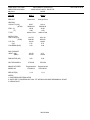
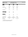
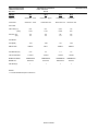
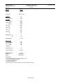
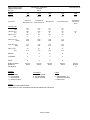
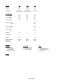
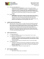
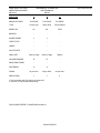
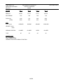
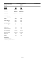
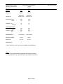
EQUIPMENT SCHEDULES ............................................................................................................ 32
3|Page
RDNO ATHLETIC PARK
AMENITIES BUILDINGS
WE File No.029042.00
May 30, 2014
1
GENERAL
1.1
1.2
1.3
1.4
1.5
1.6
1.7
1.8
1.9
1.10
1.11
1.12
1.13
1.14
1.15
2
It is the intention of these specifications and drawings to provide for a complete and fully
operating mechanical system as described herein, and in complete accord with applicable
codes and ordinances. The work to be done shall include the provision of all labour,
materials, tools and equipment as well as the application of a competent knowledge of
construction, required for the installation, testing and commissioning of the complete
mechanical system.
The drawings and specifications are a guide to establishing quality of equipment, materials,
workmanship and performance. Drawings and specifications are complementary to one
another. The term "provide" shall mean to supply and install.
References to “Consultant” in this document shall mean Williams Engineering Inc.
Any discrepancies between drawings and specifications leaving in doubt the true intent of
work shall be brought to the attention of the Consultant immediately.
Before submitting his tender, the Contractor shall examine the site and all existing
conditions affecting the work under this contract. He shall investigate and satisfy himself
that he can supply and install this work without any additional charges after award of the
Contract.
The mechanical system shall comply with the requirements of the local municipal building
by-laws, the current edition of the British Columbia Building Code, British Columbia
Plumbing Code, British Columbia Fire Code and all revisions and amendments thereto.
The Contractor shall pay all fees, obtain all permits required, and obtain inspections and
approvals from the inspection authority.
Furnish a written guarantee stating that all equipment supplied and all work executed
under this contract will be free from defects of materials and workmanship for a period of
one (1) year from the date of acceptance of the completed contract, and further that any
defective materials that become evident during the guarantee period will be corrected at no
additional cost to the Owner.
Employ only tradesmen having valid provincial trade certificates related to their work. All
work shall be executed in a workmanlike manner and shall present a neat and finished
appearance when completed. Workmanship shall be in accordance with recognized trade
standards.
All materials used shall be new and the best of its respective kind. All equipment installed
shall be in accordance with the manufacturer's printed installation directions.
The Contractor shall familiarize himself with the building plans and shall cooperate with the
Owner so that the work will not conflict with operations. Any conflicts or defaults which
arise during the construction period must be resolved immediately.
Without additional charge or expense, make any necessary changes or additions to
accommodate the structural, electrical and architectural conditions that are required for the
completion of the work.
Insurance coverage shall be provided by the Contractor unless otherwise indicated.
Leave systems operating with work areas clean and to the satisfaction of the Consultant.
All demolished materials and equipment are the property of the contractor and shall be
removed from the site, unless otherwise directed by the Owner.
Patch and make good any materials and equipment.
DESCRIPTION OF WORK
2.1
Be responsible for all work identified or implied by the drawings and specifications,
including but not limited to;
.1
Installation and commissioning of all systems, including the equipment provided by
the Owner where noted.
4|Page
RDNO ATHLETIC PARK
AMENITIES BUILDINGS
WE File No.029042.00
May 30, 2014
.2
.3
.4
.5
3
STANDARD OF ACCEPTANCE
3.1
3.2
3.3
3.4
3.5
4
4.2
Material/products considered to satisfy the specification, but of a manufacturer other than
those named in the Specification may be submitted to the Consultant for consideration not
later than five (5) working days prior to closing of tender
Addition of manufacturer's names to the specifications will be in writing by the Consultant.
EXISTING SERVICES
5.1
6
Means that item named and specified by manufacturer and/or catalogue number forms part
of specification and sets standard regarding performance, quality of material and
workmanship and when used in conjunction with a referenced standard, shall be deemed
to supplement the standard.
Where two or more manufacturers are listed, the manufacturer's name shown underlined
or shown with a model name and/or number, was used in preparing the design. Tenders
may be based on any one of those named, provided that they meet every aspect of the
drawings and specifications.
Where other than the underlined manufacturer or named manufacturer is selected or
approved, include for the cost of any resulting work (both under this Division and other
Divisions) and any necessary redesign of installation or structure. Submit redesign
drawings for review with Shop Drawings. Maintain installation, access and servicing
clearances. Redesign drawings shall be to scale and of a standard equal to the Project
Drawings.
Where two or more items of equipment and/or material, of the same type, are required,
provide products of a single manufacturer.
A visible manufacturer's nameplate shall indicate manufacturer's name, model number,
serial number, capacity data, electrical characteristics and approval stamps.
ADDITION OF ACCEPTABLE MANUFACTURERS
4.1
5
Balancing of the air and water systems. Make provisions for easy access for air and
water balancer.
Revision and testing of the heating, ventilation, plumbing and sprinkler systems in
the area.
Disposal of all unused material.
Be responsible for the performance and commissioning of all equipment supplied
and installed for the project (including all equipment supplied by the Owner where
applicable).
Confirm locations and routings of all existing services which might be affected by the work.
Protect existing and repair any damage occasioned by the work. Accommodate work
changes in location and routing as may be necessary.
CUTTING & PATCHING
6.1
Be responsible for all cutting, patching, digging, canning and coring required to
accommodate the mechanical services. Make good all revisions to match the original
condition.
5|Page
RDNO ATHLETIC PARK
AMENITIES BUILDINGS
WE File No.029042.00
May 30, 2014
6.2
7
MISCELLANEOUS METAL
7.1
7.2
8
9.2
9.3
10.2
11.2
Lubricate all equipment prior to being operated, except sealed bearings, which shall be
checked.
Use the lubricant recommended by the manufacturer for the service for which the
equipment is specified.
ESCUTCHEONS
12.1
12.2
13
Provide removable protective guards on all exposed V-belt drives and shaft couplings in
accordance with Worker's Compensation Board requirements.
Removable access covers shall be provided for all equipment installed under this project.
LUBRICATION OF EQUIPMENT
11.1
12
Install at all concealed dampers, traps, unions, valves, water hammer arrestors, special
equipment, and trap primers.
Locate access doors so that all concealed items are readily accessible for adjustment,
operation and maintenance.
Do not locate access doors in feature wall or ceiling construction without the prior approval
of the consultant. Locate in service areas wherever possible.
GUARDS AND COVERS
10.1
11
Install all work so as to be readily accessible for adjustment, inspection, operation and
maintenance.
ACCESS DOORS
9.1
10
Be responsible for all miscellaneous steel work relative to the Specifications, including but
not limited to support of equipment.
All steel work shall be prime coated, ready for paint finish.
ACCESSIBILITY
8.1
9
Verify the location of existing service runs and structural reinforcement within existing roof,
floors and walls prior to cutting. Cutting of structural building components shall only take
place upon the receipt of specific written approval of the Structural Consultant. Repairs to
existing services damaged as a result of cutting is included in this section of the work.
Provide escutcheons on all pipes passing through finished walls, floors and ceilings.
Escutcheons shall be chrome plated or stainless steel suitable for dimensions of piping and
insulation.
PAINTING
13.1
Clean exposed bare metal surfaces supplied under Division 15 removing all dirt, dust,
grease and millscale. Apply at least one coat of corrosion resistant primer paint to all
supports and equipment fabricated from ferrous metal. Paint all exposed ducts, equipment
and supports with two finishing coats of paint; color to be as directed by the Owner.
6|Page
RDNO ATHLETIC PARK
AMENITIES BUILDINGS
WE File No.029042.00
May 30, 2014
13.2
13.3
14
PENETRATION OF FIRE SEPARATIONS
14.1
15
Seal all pipe and duct penetrations through fire separations with "3M Fire Barrier" system
or equal U.L. Listed system.
TEMPORARY USE OF MECHANICAL SYSTEMS
15.1
15.2
15.3
15.4
16
Paint all pipe hangers and exposed sleeves, in exposed areas, with a rust inhibiting primer,
as they are installed.
Repaint all marred factory finished equipment supplied under Division 15, to match the
original factory finish.
Obtain written permission from the Consultant if it is desired to use the mechanical
systems for temporary heat.
The following conditions must be confirmed prior to the use of the mechanical systems for
temporary heating.
.1
Any equipment start-ups shall comply with specified procedures.
.2
All sanding must be complete, spray painting must be complete.
.3
The contractor must pay for the gas/electricity.
.4
All inspectors approvals must be received.
.5
Lubricate all equipment operated.
.6
Alarms/controls must be operational.
During the temporary heating period, comply with the following conditions:
.1
Keep all rooms broom clean.
.2
Maintain chemical treatment of piping systems.
.3
Maintain the systems.
.4
Operate the units utilizing 100% outside air if possible to avoid pulling building air
into the return ducts and the units.
Before handing the systems over to the Owner, comply with the following conditions:
.1
Bring plant to” as-new” conditions.
.2
Replace all panel type air filters installed under this contract with new filters.
.3
Re clean ductwork as necessary and provide a report from the approved duct
cleaning agency certifying that the ductwork is clean.
SYSTEMS COMMISSIONING, VERIFICATION AND DEMONSTRATION
16.1
16.2
16.3
16.4
Be responsible for the performance and commissioning of all equipment provided under
Division 15. Commissioning is the process of advancing the installation from the stage of
static completion to full working order to specified requirements. It is the activation of the
completed installation.
Acceptable Commissioning Contractors: BC Tech Engineering Services, R.A. Bruce
Associates, Inland Technical Services, MDT Systems, Western Mechanical Services, KD
Engineering.
In consultation with the General Contractor, ensure that sufficient time is allowed and fully
identified on the construction schedule for the proper commissioning of all mechanical
systems.
Commissioning is concluded when mechanical systems have been balanced and the
installation is in full working order and acceptable for use. The work will include the
following:
7|Page
RDNO ATHLETIC PARK
AMENITIES BUILDINGS
WE File No.029042.00
May 30, 2014
.1
.2
.3
.4
.5
.6
16.5
16.6
16.7
Balancing of the air systems as specified.
Balancing of the liquid systems as specified.
Balancing of domestic hot water recirculation systems.
Set up air diffusers, registers and grilles for optimum distribution/comfort.
Plug all air pressure and flow measuring holes.
Adjust vibration isolators and seismic restraints for optimum performance. Provide
letter of certification.
.7
Verification of tight closure of outside air dampers.
.8
Verification and certification of operation of all fire dampers.
.9
Verification and certification of the sealing of all HVAC penetrations through fire
separations (rated & non-rated) and sound separations.
.10
Verification of water tightness of all roof and exterior wall penetrations.
.11
Verification that all coil drain pans operate.
.12
Verification that equipment is not short cycling.
.13
Verification of fire extinguisher pressures.
.14
Verification of operation of all mechanical related fire alarm functions.
.15
Set up all automatic control valves/dampers and automatic temperature control
devices.
.16
Testing and debugging of the Building Automation System.
.17
Set up and test all alarm and protective devices.
.18
Obtain and review trend logs for all control points. Submit trend logs to Consultant
with detailed comments after verification of proper operation of all control
sequences.
.19
Verification and certification of sewage and septic system installations.
At the conclusion of commissioning, demonstrate the operation of the systems to the
Consultant and then to the Owner's Operating Staff.
At the completion of the commissioning, testing, balancing and demonstration submit the
following to the Consultant:
.1
A letter certifying that all work specified under this contract is complete, clean and
operational in accordance with the specification and drawings.
.2
Completed copies of all commissioning check lists plus copies of start-up reports
from specialty contractors and vendors.
.3
Signed off Williams Engineering Inc. field reports.
.4
"AS-BUILT" record drawings, as specified.
.5
B.C. Boiler Inspection Dept. approval of boiler, pressure vessels and pressure piping
installations.
.6
B.C. Gas Inspection Dept. approval of boiler on gas firing.
.7
Fire Commissioner's approval of oil fuel installations.
.8
A list of all alarm and protective devices tested, with the final operating settings.
The verification process shall include instructional seminars to demonstrate all systems
and to explain the operation of each. The instruction shall include the following:
.1
Ease of access provided throughout for servicing coils, filters, motors, drives, fusible
link fire dampers, control dampers and damper operators.
.2
Operation of all equipment and systems under each mode of operation and failure,
including:
.1
Building Automation System control features.
.2
Boilers and associated fuel systems.
.3
Air conditioners and refrigeration systems.
8|Page
RDNO ATHLETIC PARK
AMENITIES BUILDINGS
WE File No.029042.00
May 30, 2014
.3
17
SUBSTANTIAL PERFORMANCE REQUIREMENTS
17.1
17.2
18
.4
Pumps, fans, heaters, unit heaters and coils.
.5
Sprinkler fire protection systems.
.6
Sewage and septic installations.
.7
Tanks - domestic hot water and expansion.
After demonstration obtain the Owner's signature certifying that the demonstration
has been performed and completed to their satisfaction.
Before the Consultant is requested to make an inspection for Substantial Performance of
the work:
.1
Commission all systems and prove out all components, interlocks and safety
devices.
.2
Submit a letter certifying that all work (including calibration of instruments and
balancing of systems) is complete, operational, clean and all required submissions
have been completed.
The work will not be considered to be ready for use or substantially complete until the
following requirements have been met:
.1
All life safety items are completed and fully functional.
.2
All reported deficiencies have been corrected.
.3
Testing and balancing completed.
.4
Operating and Maintenance Manuals completed.
.5
"As Built" Record Drawing ready for review.
.6
System Commissioning has been completed and has been verified by Consultant.
.7
All demonstrations to the Owner have been completed.
OPERATING & MAINTENANCE MANUALS
18.1
18.2
18.3
18.4
Prepare instruction manuals which include equipment manufacturers' operating and
maintenance bulletins, a report on the balancing of the air and water systems and a report
on chlorination of water mains. The manuals shall be prepared by the Commissioning
Contractor.
The manufacturers' bulletins shall include:
.1
General description of the equipment and their operation.
.2
Normal maintenance and minor trouble-shooting of each major item.
.3
Wiring diagrams.
.4
Control diagrams.
.5
Spare parts list.
.6
Local source of supply.
Submit three copies in suitably labeled hard cover binders, to the Consultant at least ten
days prior to the Substantial Performance inspection date.
Provide a CD-ROM based copy of the Operating & Maintenance Manuals described
above.
.1
The CD-Rom shall consist of all data in the manuals, arranged in a “pdf” format file,
with an interactive menu system of bookmarks to match the manual format.
.2
Include the latest version of Adobe Acrobat Reader.
.3
Include “pdf” format copies of the as-built project drawings (contact the consultant
for files).
9|Page
RDNO ATHLETIC PARK
AMENITIES BUILDINGS
WE File No.029042.00
May 30, 2014
.4
19
SYSTEMS BALANCING
19.1
19.2
19.3
19.4
19.5
19.6
19.7
20
The Contractor shall provide 6 copies of shop drawings of all equipment for the
Consultant’s review. Submit clear and descriptive control sequences prior to installation.
AS-INSTALLED RECORD DRAWINGS
21.1
21.2
21.3
22
Adjust duct and terminal balance dampers, adjustable air turning devices and adjust or
change drive sheaves to balance supply, return and exhaust air systems to provide the
design air quantities (within +/-10%) at each outlet and inlet and to maintain the design
relationship between the supply and exhaust air system quantities. Refer to the drawings
for air quantities.
Acceptable Balancing Contractors: BC Tech Engineering Services, R.A. Bruce Associates,
Inland Technical Services, MDT Systems, Western Mechanical Services, KD Engineering.
Adjust all air terminals to obtain the optimum air distribution pattern.
Adjust all air flow and pressure sensing devices.
Adjust the new water systems to design flow conditions.
Adjust the domestic hot water recirculation system flow rates.
Include 3 copies of a balance report for inclusion into the manuals.
SHOP DRAWINGS
20.1
21
Submit the CD-ROM to the consultant for review and comment. Incorporate any
suggested revisions.
Maintain one set of record drawings at the site. Clearly mark in red any changes or
deviations from the original design intent. Record all changes to the work as the
installation progresses.
At the completion of the work, certify the drawing as being accurate, mark the drawing as
"AS-BUILT", and send to the Consultant upon Substantial Performance of this Contract.
Include in the tender price an allowance of $850.00 to transfer changes to the original
documents. Coordinate changes to the original documents with the Consultant.
IDENTIFICATION
22.1
Each piping system shall be colour coded for identification and labeled with the system
identification code letters, including temperature and pressure, if applicable, and directional
flow arrows.
.1
Identify all new piping to existing building identification standards.
.2
Identify piping adjacent to valves and where valves are in series at no more than 2m
[6'-6"] intervals. Identify piping at least once in each room and at 15m [50ft.]
maximum spacing in open areas. Exception: gas piping to be identified at 2m [6'-6"]
intervals in ceiling plenums.
.3
Identify piping both sides where piping passes through walls, partitions and floors.
Identify piping at point of entry and leaving each pipe chase and/or confined space.
Identify piping accessible at each access opening.
.4
Identification labels may be stenciled. Identification arrows labels and letters may be
vinyl cloth (Brady B500) or vinyl film (Brady B946), with adhesive compatible with
the surface temperature.
10 | P a g e
RDNO ATHLETIC PARK
AMENITIES BUILDINGS
WE File No.029042.00
May 30, 2014
.5
22.2
22.3
23
SPARE PARTS
23.1
24
Provide spare parts for the Owner as follows:
.1
one set of v-belts for each new piece of equipment.
.2
one set of filter media for each filter or filter bank installed.
.3
One box (12 cartridges) for each water filter installed.
VIBRATION ISOLATION
24.1
24.2
25
Identification colour bands for primary and secondary colours to indicate the type
and degree of hazard shall be applied to overlap a minimum of 50mm [2"]. Bands
shall be Brady B550 vinyl cloth tape or Brady B946 vinyl tape, with adhesive
compatible with the surface temperature.
Each piece of equipment shall be identified with its equipment schedule identification, e.g.
supply fan SF-1, cooling coil CC-1, pump P-1.
.1
Provide laminated plastic plates with black face and white centre of minimum size
90mm x 40mm x 2.5mm [3-1/2" x 1-1/2" x 3/32"] engraved with 12mm [1/2"] high
lettering. Use 25mm [1"] high lettering for major equipment.
.2
Apply nameplates securely in conspicuous places, on cool surfaces.
Secure 6mm [1/4"] self adhesive coloured dots, (Brady Quik Dots or Avery Data Dots), to
the ceiling, to identify the location of access to equipment concealed above the ceiling
Provide vibration isolation on all motor driven equipment with motors of ½ HP and greater
power output (as indicated on the motor nameplate) and on piping and ductwork, as
specified herein. For equipment less than ½ HP, provide neoprene grommets at the
support points.
Provide 20mm [3/4"] thick continuous perimeter closed cell foam gasket to isolate base of
package type equipment, AHU's, exhaust fans, etc. from floors, roofs and roof curbs.
Select width for nominal 3 psig loading under weight of equipment and allow for 25%
compression, 5mm [3/16"]. Increase width of curb using steel shim if necessary to
accommodate gasket. For light equipment such as exhaust fans, deflection should be a
minimum of 0.05". Use hold down bolts selected for seismic loads. Isolate bolts from base
of unit using neoprene hemi-grommets. Avoid compressing gasket (eg. use Hilti HVA
adhesive set bolts, or equal, with steel washers and lock nuts, adjusted finger tight to the
hemi-grommets). Size bolt and hemi-grommet for minimum lateral clearance. Standard of
Acceptance: American National Rubber-EPDM-SBR blend SCE 41 type self-extinguishing
neoprene, Mason Industries Type HG Hemi-Grommets
SEISMIC RESTRAINTS
25.1
25.2
25.3
25.4
Provide cable restraints on all isolated equipment and seismic restraint on all other
equipment, piping and ductwork, all in general accordance with SMACNA Guidelines
Include in the Tender the services of a BC Professional engineer, regularly employed in the
design of restraint systems to review and sign-off on all seismic supports and restraints.
Submit "sealed and signed" Letters of Assurance from the Seismic Engineer.
It is the entire responsibility of equipment manufacturers to design their equipment so that
the strength and anchorage of internal components of the equipment exceeds the force
level used to restrain and anchor the unit itself to the supporting structure.
All resiliently mounted equipment, including piping and ductwork, shall be provided with
seismic restraining devices (snubbers).
11 | P a g e
RDNO ATHLETIC PARK
AMENITIES BUILDINGS
WE File No.029042.00
May 30, 2014
25.5
25.6
25.7
25.8
25.9
25.10
26
Air terminals installed in grid ceilings on flexible duct shall have at least two galvanized
steel seismic restraint wires attached to the building structure or to ceiling hanger wires.
Attach security bridles at opposite corners of each air terminal and in such a manner that
the air terminal cannot fall.
Air terminals installed in grid ceilings on rigid duct shall have at least two screws securing
the air terminal to the duct.
Air terminals installed in grid ceilings not attached to ducts shall have at least two screws
securing the air terminal to the ceiling support or at least two galvanized steel seismic
restraint wires attached to the building structure or to ceiling hanger wires.
Provide galvanized steel seismic restraint wires for radiant ceiling panels attached to either
building structure or to ceiling hanger wires.
Roof top unit systems shall have roof curb/support bolting restraint systems designed by a
BC Professional engineer, regularly employed in the design of restraint systems. Submit
"sealed" shop drawings for review by the Consultant.
Slack Cable Systems
.1
Slack cable restraints as supplied by Vibra-Sonic Control.
.2
Restraint systems as detailed in SMACNA "Guidelines for Seismic Restraints of
Mechanical Systems and Plumbing Piping Systems" as reviewed by the "Office of
the State Architect, Structural Safety Section" for California. If lesser restraint than
recommended by SMACNA is proposed to meet local NBCC seismic requirements,
provide shop drawings of details certified by a B.C. registered structural consultant.
DUCTWORK AND ACCESSORIES
26.1
26.2
26.3
26.4
26.5
26.6
26.7
26.8
Galvanized steel, lock forming quality. All ductwork to be constructed, braced, connected
and jointed according to ASHRAE and SMACNA.
Provide stainless steel ductwork where noted on the drawings.
Snaplock seams and crimp joints are not acceptable.
All duct joints, indoor and outdoor, shall be completely sealed with an approved sealant.
Sealants shall meet acceptable smoke and flame spread ratings.
Provide gauge of metal and bracing as required for 500 Pa [2" w.c.] static pressure or
greater.
Install duct necks before grilles, registers and diffusers and cushion heads after diffuser
take-offs. Provide maximum of 24" of flexible connection. Do not use flex to change
directions.
Where flexible ductwork is used, provide factory fabricated insulated flex.
.1
Flexible vinyl coated steel helix bonded to inner duct liner. Fibrous glass thermal
insulation.
.2
Outer jacket of metalized fire-resistant vapour barrier.
.3
Suitable for up to 500 Pa [2" w.g.] positive static pressure and/or 250 Pa [1" w.g.]
negative static pressure.
.4
UL or ULC labeled, Class 1, duct connector.
.5
Connect to ductwork using two wraps of duct tape and stainless steel worm drive
clamps or Panduit adjustable diameter clamps or Thermaflex duct strap.
Provide backdraft dampers where indicated on the drawings.
.1
Minimum Requirements:
.1
1.4 mm thick [16 ga] galvanized steel or aluminum channel frame.
.2
1.2 mm thick [15 ga] aluminum blades, complete with stiffening ribs/bends.
.3
Full blade length shafts; brass, ball or nylon bearings.
12 | P a g e
RDNO ATHLETIC PARK
AMENITIES BUILDINGS
WE File No.029042.00
May 30, 2014
.4
.5
.6
.7
.8
26.9
26.10
26.11
26.12
26.13
Felt or neoprene anti-chatter blade strips.
Blade connecting linkage with eyelet and pin bearings.
Maximum blade length of 760 mm [30"], use multiples for larger dimensions.
Manufacturer's label.
Where a balanced backdraft damper (BBD) is indicated the damper shall
incorporate an adjustable counterbalance weight and lever.
.9
Maximum pressure drop across damper at 4.06 m/s [800 FPM] shall be 45 Pa
[0.18" w.g.]
.10
Standard of Acceptance: Airolite 625, Penn CBD-6.
Provide heavy duty opposed blade balance dampers with locking quadrant on each run out
to a grille or diffuser and where indicated on the drawings.
.1
Identify the airflow direction and blade rotation and open and closed position.
.2
Provide sheet metal bridge to raise quadrant type operators above the insulation
thickness. Provide open end bearings where bridges are used.
.3
The damper operating lever shall be arranged parallel with the damper blade.
Wire Mesh Screens
.1
Provide wire mesh screens in all air intake openings where noted on the drawings.
.2
Screens shall be constructed from aluminum wire 1.3 mm diameter [16 ga].
.3
Screen mesh shall be 12.7 mm [1/2"].
Provide fire stop flaps where indicated on the drawings. Fire stop flaps shall be single
damper flap with spring catch, U.L.C. tested and labeled. Construct of minimum 1.35 mm
[16 ga] thick sheet steel with 1.6 mm [1/16"] thick [asbestos] on unexposed side and
corrosion-resistant pins and hinges. Arranged so as not to reduce duct free area. Provide
thermal blanket as required. Standard of Acceptance: Ruskin CFSF.
Provide fire dampers where indicated on the drawings.
.1
Fire dampers shall be U.L.C. or Warnock Hersey tested and labeled. Fire dampers
shall be curtain type, fusible link actuated, weighted to close and lock in closed
position when released or having negator-spring-closing operator for multi-leaf type
in horizontal position with vertical air flow. Curtain fire dampers shall have blades
retained in a recess so free area of connecting ductwork is not reduced. Standard of
Acceptance: Ruskin, Nailor Hart, Controlled Air.
.2
Install in accordance with the SMACNA Fire, Smoke and Radiation Damper
Installation Guide for HVAC Systems - Fourth Edition 1992.
.3
Size so that the free area of the duct is maintained through the assembly.
.4
Install in galvanized steel sleeve, retained in place with retaining angles on all four
sides at each face of wall.
.5
Connect ductwork to damper sleeves using break-away duct joints on all faces.
.6
Fire dampers must be installed within wall thickness of fire separation.
.7
Use ULC approved fire stop sealant to caulk all joints between the fire damper
sleeve angles and the sleeve and between the fire damper sleeve angles and the
fire separation.
Duct and Plenum Access
.1
Provide access doors and panels as follows:
.1
Doors: where shown on the drawings.
.2
Panels:
.1
Every 12 m [40 ft] on all ductwork.
.2
At the base of each duct riser.
.3
Both sides of equipment blocking the duct, (e.g. air flow measuring
stations, coils)
13 | P a g e
RDNO ATHLETIC PARK
AMENITIES BUILDINGS
WE File No.029042.00
May 30, 2014
.4
.5
At or to one side of other equipment in duct, (eg. Backdraft dampers,
balancing dampers serving multiple inlets/outlets,
Panels need not be provided where access is available through a door
or a register mounted on the side of the duct.
.2
26.14
26.15
26.16
27
Products:
.1
Doors - construct in accordance with SMACNA Duct Standards Fig. 6-12
except for latch type. 40mm [1-1/2"] thick insulation.
.2
Panels - Nailor Hart, Ventlok, 25 mm [1"] thick insulation.
.3
Gaskets - neoprene or foam rubber.
.3
Hardware:
.1
Panels up to 400mm x 300mm [16"x12"] - 2 sash locks.
.2
Panels - 380mm x 500mm [15"x20"] - 4 sash locks.
.3
Doors - piano hinge and Ventlok 310 latches c/w front and inside handles and
front door pull.
.4
Installation:
.1
Seal frames airtight.
.2
Install so as to not interfere with airflow.
.3
Install to provide easiest possible access for servicing and cleaning.
.4
Do not use sheet metal screws for attaching access panels to ductwork.
.5
Round ducts 330mm [13”] and larger shall include a short collar for the
installation of access panels.
.6
Small rectangular ducts shall be transitioned for the installation of access
panels.
Provide thermal breaks at all roof and wall penetrations.
Provide flexible canvas duct connections on all fan equipment.
Before handing the systems over to the Owner, comply with the following conditions:
.1
As a condition of acceptance all new and /or existing air ductwork systems shall be
clean. The Contractor shall confirm system cleanliness in writing and shall assume
responsibility for misinformation and correction of damage. Before starting fan
systems, all supply outlets shall have clean cheesecloth attached to them.
.2
Final systems cleaning shall be performed by an approved Cleaning Agency.
.3
The cleaning shall be to the satisfaction of the Consultant and Owner.
.4
Provide a report from the approved duct cleaning agency certifying that the ductwork
is clean.
.5
Provide new filters for all air handlers after cleaning has been completed.
PIPING INSTALLATION
27.1
27.2
27.3
27.4
27.5
27.6
27.7
Ream pipe ends. Clean scale and dirt, inside and outside before and after assembly.
During construction, protect all openings in piping and equipment, by capping or plugging
to prevent entry of dirt.
Connect to equipment in accordance with manufacturer's instruction unless otherwise
indicated.
Slope supply piping up (1:480) in direction of flow and drain from low points. Slope return
piping down (1:480) in the direction of flow.
Use eccentric reducers at pipe size change installed to provide positive drainage.
Provide clearance for access for maintenance of equipment, valves and fittings.
Install unions or flanges in connections to all equipment and specially components.
14 | P a g e
RDNO ATHLETIC PARK
AMENITIES BUILDINGS
WE File No.029042.00
May 30, 2014
27.8
27.9
27.10
27.11
27.12
27.13
27.14
27.15
28
THERMOMETERS AND GAUGES
28.1
28.2
28.3
29
Arrange piping connections to allow ease of access and for removal of equipment.
Align and independently support piping connections adjacent to equipment to prevent
piping stresses being transferred.
Install valves with stems upright or horizontal unless approved otherwise.
Install valves to isolate each piece of equipment, and as indicated.
Construct piping to allow for expansion and contraction.
Tests and Cleaning
.1
Hydrostatically test all pipes for at least 8 hours prior to insulating.
.2
Repair all leaks as required for zero loss.
.3
Chemically clean and flush all new hydronic and steam piping prior to reconnection
to equipment.
.4
Thoroughly flush all new domestic water piping.
Provide chemical treatment to match existing as required to refill system.
Provide chemical treatment and test kit for the hot water heating system.
.1
The Chemical Treatment Agency shall provide supervision of installations, set-up
and adjustment and shall submit a written report on system operations.
.2
The Chemical Treatment Agency shall instruct the maintenance personnel before
Substantial Performance. Written instructions of the treatment, dosages, control
charts and test procedures shall be included in the maintenance manuals.
Select thermometers and gauges so that their operating range falls in the middle half of the
scale range.
Thermometers shall be pipe mounted stem type in copper, brass or bronze well installed
so as not to restrict flow. Thermometers shall be non-mercury actuated adjustable angle
type, 225 mm [9"] scale length, white background with black lettering, with both Celsius
and Fahrenheit scales.
Pressure gauges shall be 115mm [4 1/2"] diameter, phosphor bronze bourdon tube type
with white background and black lettering. Provide needle valve ahead of each gauge.
Provide kPa and PSIG scales. Use extensions where gauges are installed through
insulation.
INSULATION - DUCTWORK
29.1
29.2
29.3
29.4
As applicable, use the latest edition of the "B.C. Insulation Contractors Association
(BCICA) Standards Manual" as a reference standard if sufficient detail/information is not
specified herein.
External
.1
Flexible glass fibre insulation with integral vapour barrier.
.2
Thermal Conductivity at 24°C. - 0.042 W/m/°C.
.3
Acceptable Manufacturers: Certainteed STP Ductwrap #75, Fiberglas AF300 (type
II) RFFRK, Knauf FSK Ductwrap, Manson Alley-Wrap FSK.
Acoustic Duct Liner
.1
Internal flexible glass fibre acoustical insulation with sealer coating on one face.
.2
Thermal Conductivity at 24°C. - 0.040 W/m/°C.
.3
Acceptable Manufacturers: Certainteed Ultralite #150, Knauf Duct Liner M, Manson
Akousti-liner.
Insulation Accessories
15 | P a g e
RDNO ATHLETIC PARK
AMENITIES BUILDINGS
WE File No.029042.00
May 30, 2014
.1
29.5
30
All insulation accessories (adhesives, tape, coatings, etc.) shall be approved for the
specific application.
Duct Insulation Schedule:
.1
Provide 25mm [1"] thermal insulation for outside air ducts.
.2
Provide 25mm [1"] thermal insulation for exhaust ducts for 2.5m [8'] from roof or wall
penetration.
.3
Provide 25mm [1"] thermal insulation for all interior supply ducts.
.4
Provide acoustic duct liner where noted on drawings (25mm [1”] minimum, 50mm
[2”] where noted).
.5
Adhere insulation with insulation adhesive applied in 150mm [6”] wide strips at
300mm [12”] on centre and secure with twine at 300mm [12”] on centre.
.6
Provide 50mm [2”] insulation with waterproof jacket on all cooling and heating supply
ducts located outdoors.
INSULATION - PIPING
30.1
30.2
30.3
30.4
30.5
30.6
As applicable, use the latest edition of the "B.C. Insulation Contractors Association
(BCICA) Standards Manual" as a reference standard if sufficient detail/information is not
specified herein.
Preformed pipe covering with integral vapour barrier.
.1
Thermal Conductivity at 24°C. - 0.033 W/m/°C.
.2
Acceptable Manufacturers: Certainteed 500 ASJ/SSL, Fiberglas 850 ASJ/SSL or
equal.
Flexible Foamed Elastomeric (refrigerant piping only):
o
o
.1
Thermal Conductivity at 24 C - 0.040 W/m/ C.
.2
Acceptable Products: AP Armaflex, Rubatex R-180-FS.
Insulation Accessories
.1
All insulation accessories (adhesives, tape, coatings, etc.) shall be approved for the
specific application.
.2
Install flexible foamed elastomeric or flexible closed cell preformed piping insulation.
Secure longitudinal and butt joints with adhesive. Insulate all fittings and
components. To obtain the specified thickness, apply in layers with staggered joints.
Insulation Termination Points
.1
Terminate insulation 75 mm [3"] back from all uninsulated fittings to provide working
o
clearance and terminate insulation at 90 and finish with reinforced scrim cloth and
vapour barrier mastic system. Cover onto pipe and over the insulation vapour
barrier. On concealed hot services terminate insulation 75mm [3"] back from all
o
uninsulated fittings, cut off at 90 and apply reinforced scrim cloth and breather
mastic system.
o
.2
Cut back insulation at 45 and finish with a silicone caulking sealant around the base
of thermometer wells, pressure gauges, flow switches and pressure and control
sensors.
Pipe Insulation Schedule:
.1
Insulate plumbing vents for 2.5m [8'] from roof penetration. Do not use flexible duct
wrap insulation.
.2
Insulate rainwater leaders for the entire length including roof drain bodies. Do not
use flexible duct wrap insulation.
.3
Insulate all valves and pipe mounted equipment.
16 | P a g e
RDNO ATHLETIC PARK
AMENITIES BUILDINGS
WE File No.029042.00
May 30, 2014
.4
.5
.6
.7
.8
31
INSULATION - EQUIPMENT
31.1
31.2
31.3
31.4
31.5
32
Provide 25mm [1"] insulation for all heating pipes 50mm [2"] and smaller. 40mm
[1.5"] for all heating pipes greater than 50mm [2"].
Provide 40mm [1.5"] insulation for all steam and condensate pipes 50mm [2"] and
smaller, 50mm [2"] for all steam and condensate greater than 50mm [2"].
Provide 25mm [1"] insulation for all domestic hot water and hot water recirculation
pipes 50mm [2"] and smaller. 40mm [1.5"] for all domestic hot water hot water and
recirculation pipes greater than 50mm [2"].
Provide 25mm [1"] insulation for all domestic cold water pipes.
P-traps, waste arms and water supplies at all handicap accessible lavatories and
sinks shall be insulated with a manufactured insulation kit or 12mm [½"] of fiberglass
insulation and finished with a polyvinyl chloride jacket in a neat and workmanlike
manner. Acceptable Manufactured Products: Truebro 'Handi Lav-Guard', Brocar
Products Inc. 'Trap Wrap', Sexauer 'Handi Lav-Guard'
As applicable, use the latest edition of the "B.C. Insulation Contractors Association
(BCICA) Standards Manual" as a reference standard if sufficient detail/information is not
specified herein.
Flexible glass fibre insulation with integral vapour barrier.
.1
Thermal Conductivity at 24°C. - 0.042 W/m/°C.
.2
Acceptable Manufacturers: Certainteed STP Ductwrap #75, Fiberglas AF300 (type
II) RFFRK, Knauf FSK Ductwrap, Manson Alley-Wrap FSK.
Rigid glass fibre insulation with integral vapour barrier.
.1
Thermal Conductivity at 24°C. - 0.042 W/m/°C.
.2
Acceptable Manufacturers: Certainteed STP Ductwrap #75, Fiberglas AF300 (type
II) RFFRK, Knauf FSK Ductwrap, Manson Alley-Wrap FSK.
Insulation Accessories
.1
All insulation accessories (adhesives, tape, coatings, etc.) shall be approved for the
specific application.
Equipment Insulation Schedule:
.1
Provide 40mm [1.5"] foil faced glass fibre insulation on top of each radiant panel to
fully cover panel and interconnecting piping.
DOMESTIC WATER SYSTEMS - PIPING, VALVES AND FITTINGS
32.1
32.2
32.3
Piping and Fittings
.1
Hot and cold water and hot water recirculation piping: Type L copper with wrot
copper fittings and 95/5 Sn/Sb, Silvabrite 100 or other lead free solder joints.
Gate Valves
.1
Solder or screwed end joints 50mm [2"] and smaller: Crane 1320 or 428, Jenkins
300P or 810, Lunkenheimer 2133 or 2127, Red & White 281A or 280, NeumanHattersley A41SE or A40AT / 33X, Kitz 41 or 40.
.2
Flanged ends 65mm [2½"] and larger: Crane 465-1/2, Jenkins 404, Lunkenheimer
1430C, Red & White 421A, Neuman-Hattersley 504, Kitz 72.
Ball VaLves
.1
Ball: (in lieu of gate valves or as specified)
.2
50mm [2"] and smaller, brass two piece body, blow-out proof stem, PTFE seats,
brass chrome plate ball, lever handle operator, 1035 kPa [150 PSIG] rating.
17 | P a g e
RDNO ATHLETIC PARK
AMENITIES BUILDINGS
WE File No.029042.00
May 30, 2014
.3
32.4
32.5
32.6
32.7
32.8
32.9
Acceptable Products:
.1
Solder joint type: Red & White / Toyo 5049A, Apollo, Crane, Jenkins, Kitz,
Lunkenheimer 746FS or 747FS, Neuman-Hattersley, Nibco, Watts,
Worcester.
.2
Threaded joint type: Red & White / Toyo 5044A, Apollo-70 Series, Crane 93TF, Grinnell 3700 full port, Jenkins-1101-T, Kitz 58, Lunkenheimer 746F or
747F, Neuman-Hattersley 1969AT, Nibco T-580-BR, Watts B-6000,
Worcester 4211-RT.
Balance: (for domestic hot water recirculation)
.1
30mm [1¼"] and smaller, globe lockshield, for maximum system temperature,
bronze body and trim, Teflon; polytetrafluoroethylene (PTFE), disc, female by male
union connection, 690 kPa [100 psig] rating. Acceptable Products: Dahl 13012 or
13013 with memory stop, Dunham Bush 840A, Red & White / Toyo 250LS or 251LS,
Grinnell GBV-T threaded.
.2
40mm [1½"] and larger, plug type, wrench adjustable stop, for maximum system
o
temperature, semi-steel body, resilient plug seals, EPT or RS 55, max. 120 C
o
[250 F] operating temperature, 860kPa [125 psig], threaded end connections for up
to 50 mm [2"], flanged end connections on 65mm [2½"] and larger. Acceptable
Products: DeZurik 435 with 487 adjustable stop, Homestead Ballcentric, NeumanHattersley 170M or 171M, Grinnell GBV-T or GBV
Vacuum relief: (for hot water tanks installations)
.1
Up to 12 mm [½"], 860 kPa [125 psig] rating. Acceptable Products: 12 mm [½"]
Watts 36A, Cash Acme.
.2
19 mm [¾"] and larger, 860 kPa [125 psig] rating. Acceptable Products: 18 mm
[3/4"] Watts 36A, Cash Acme.
Pressure Reducing Valves:
.1
6 mm [¼"] to 9 mm [3/8"] ,860 kPa [125 psig] rating. Acceptable Products: Watts
215, Cash Acme, Singer.
.2
12 mm [½"] to 50 mm [2"], 860 kPa [125 psig] rating. Acceptable Products: Watts
223, Braukman, Conbraco, Cash Acme, Singer.
.3
65 mm [2½"] and larger, 860 kPa [125 psig] rating. Acceptable Products: BCA 317
PR, Clayton 90 or 90B, Singer 106PR.
Pressure reducing valve with integral low flow bypass:
.1
40 mm [1½”] and larger, 860 kPa [125 psig] rating. Acceptable Products: Watts PV10-06M, Clayton, Singer.
Water Meter:
.1
The water meter shall be supplied by the Contractor and shall be to Municipal
Standards.
.2
Hermetically sealed direct reading centre sweep register, one piece cast bronze
main case, nutating disc measuring chamber with flow control adjustment,
magnetically driven, rated for 1035 kPa [150 psig] service, reading in cubic metres
and flanged ends conforming to AWWA C700.
.1
Acceptable Products: Neptune Trident 8, Rockwell, Hersey
.3
Self generating remote meter reader to suit municipal requirements.
.4
Size meter for a maximum of 35 kPa [5 psig] pressure drop at design flow rates.
Pressure Reducing Valves Installation:
.1
Pressure reducing valve stations, as a minimum shall consist of the following:
18 | P a g e
RDNO ATHLETIC PARK
AMENITIES BUILDINGS
WE File No.029042.00
May 30, 2014
.1
.2
.3
33
DRAIN, WASTE AND VENT SYSTEMS - PIPING AND FITTINGS
33.1
33.2
33.3
34
A high flow or main pressure reducing valve; which shall be one pipe size
smaller than the incoming or outflowing building service, and shall be
provided with a strainer, a reducer and a shut off valve on the inlet side and a
reducer and a shut off valve on the outlet side.
.2
A low flow pressure reducing valve; which shall be 25 mm [1"] in size, and
shall be provided with a strainer and a shut off valve on the inlet side and a
shut off valve on the outlet side.
.3
A bypass around both pressure reducing valves with a normally closed globe
valve; which shall be of the same pipe size as the incoming or outflowing
building service, and a pressure gauge on each side of the globe valve.
.4
Where a pressure reducing valve with integral low flow bypass is used the
piping, fittings and accessories shall be arranged as described above.
Set main pressure reducing valve at 415 kPa [60 psi] outlet pressure.
Set small flow pressure reducing valve at 35 kPa [5 psi] higher outlet pressure than
main pressure reducing valve.
Piping and fittings - above grade
.1
Waste and vent piping 50mm [2"] and smaller: DWV copper with cast brass fittings
and solder joints.
.2
Waste and vent piping 65mm [2.5"] and larger: Cast iron soil pipe and fittings with
mechanical joint couplings.
Piping and fittings - below grade
.1
Acrylonitrile-Butadiene-Styrene (ABS) Drain Waste and Vent Pipe Fittings
conforming to CSA CAN 3-B181.1.
.2
Polyvinyl Chloride (PVC) Drain Waste and Vent Pipe and Pipe Fittings conforming to
CSA B181.2.
Install cleanouts as shown on the drawings and as required by the B.C. Plumbing Code.
REFRIGERATION SYSTEMS
34.1
34.2
34.3
34.4
34.5
Do refrigeration system work in accordance with latest version of B.C. Power Engineers
and Pressure Vessels Safety Act and Regulations ("Refrigeration Code"), CSA B52 and
ANSI B31.5.
Ensure that a permit is obtained before anyone commences to install or alter any
refrigeration system.
Every person who installs or makes alterations or repairs to a refrigeration system shall be
the holder of a valid and subsisting refrigeration contractor’s license and all persons
repairing equipment with ODS/CFC's shall have completed an Environment Canada
approved training program.
Refrigerant Tubing
.1
Provide processed tubing for refrigeration installation, deoxidized, dehydrated and
sealed.
.2
Hard copper tube, type L, to ASTM B88M.
.3
Annealed copper tube to ASTM B280, with minimum wall thickness as per CSA B52.
Fittings
o
o
.1
Service: design pressure 2070 kPa [300 psig] and temperature 121 C [250 F]
.2
Brazed: wrought copper to ANSI B16.22 or cast bronze to MIL-F-1183E.
.3
Flare: Bronze or brass, for refrigeration, to ANSI B16.26.
19 | P a g e
RDNO ATHLETIC PARK
AMENITIES BUILDINGS
WE File No.029042.00
May 30, 2014
34.6
34.7
34.8
34.9
34.10
34.11
34.12
34.13
34.14
34.15
.4
Long radius type for elbows and return bends.
Joints
.1
Brazing materials shall be SIL-FOS-15 phosphor-copper-silver alloy for copper
piping jointed by copper fittings and silver solder for brass fittings.
.2
Flexible connections: 3/8” nominal or less shall be made using coiled soft copper
tubing. For larger sizes, use seamless flexible bronze hose with bronze wire braid
covering. Use factory sealed neoprene jacket unit where freezing may occur.
Shut-Off Valves:
.1
Line size; selected for low pressure drop.
Solenoid Valves:
.1
With field replaceable coil, serviceable without removing valve from line.
.2
Coil voltage to suit field requirements.
.3
Provide upstream of thermostatic expansion valves.
.4
Acceptable Products: Alco 240 RA series.
Expansion Valves:
.1
Thermostatic type with external equalizer, adjustable superheat setting, capacity and
bulb charge to suit operating conditions.
Water Regulating Valves:
.1
Pressure activated two-way straight-through type.
.2
For three-way regulators, install balancing valve in by-pass, adjusted to maintain
constant system flow rate irrespective of valve position.
Charging and Purging Valves
.1
Valves to be the same size as line size into which they are connected or ½”
whichever is the larger.
.2
Valve complete with a removable seal cap chained to the valve body.
.3
Acceptable Products: Henry Standard type, Mueller Linemaster Special.
Sight Glass
.1
Provide sight glass in liquid line following filter drier.
.2
Sight glass shall be combination moisture-liquid indicator and with a protective
removable cap.
.3
Sight glass to be fitted in-line.
.4
Acceptable Products: Henry Dri-Vue, Mueller Vuemaster, Sporlan See All.
Access Fittings
.1
Provide Schraeder access fittings in each suction connection from an evaporator,
located adjacent to the superheat sensing element of the expansion valve.
.2
Fittings to be used for checking the superheat of the suction gas.
.1
Access fitting shall be soldered into a tee and shall be complete with a quickseal cap.
Filter Drier
.1
Provide a filter drier in the liquid line from the condenser. Shut-off valves shall be
installed on each side of drier and sight glass.
.2
Filter drier shall be selected to have a pressure drop of not more than 13 kPa [2
psig] when passing 150% of the system flow rate.
.3
Removable core with flare connections.
.4
Acceptable Products: Alco Extra-Klean, Catch-All, Henry Dri-Cor, Mueller
Drymaster II, Sporlan.
Flexible Connections
.1
Braided tin-bronze convoluted flexible connections.
20 | P a g e
RDNO ATHLETIC PARK
AMENITIES BUILDINGS
WE File No.029042.00
May 30, 2014
34.16
34.17
34.18
35
.2
Design pressure 2070 kPa [300 psig].
.3
Acceptable Products: Anaconda
Install the following accessories:
.1
Ball check isolating valves at receiver sight glass.
.2
Charging valve for high and low side filter drier, solenoid valve and thermostatic
expansion valve.
Refrigerant Tests
.1
Each refrigerant system shall be tested as follows before operation with dry nitrogen
gas to a pressure not less than 1.5 times the system working pressure. During the
test, each joint shall be tested for leaks with a solution of soap and water.
Compressors with refrigerant holding charge shall remain isolated from system.
.2
The system shall then be evacuated to not less than 33.25 Pa (250 microns)
absolute and left for 24 hours, during which time the pressure shall not have
increased more than 33.25 Pa (250 microns). The system shall then be pressurized
to 14 kPa [2 psig] with refrigerant to be used and shall be evacuated to 66.5 Pa [500
microns] absolute and then shall be immediately fully charged with the refrigerant to
be used in the system and each joint checked with an electronic testing device.
Tests shall be performed before insulation is applied.
.3
All damaged or defective components shall be replaced with new (not reconditioned)
components.
Start-Up and Adjustment
.1
Provide necessary instruments, gauges and testing equipment required. Adjust
controls, to obtain design requirements and manufacturer's ratings.
.2
Test and record cooling apparatus entering and leaving air temperatures, dry bulb
and wet bulb.
.3
Test and record voltage and running amperes and compare to motor nameplate
data, and starter heater rating against design requirements.
o
o
.4
Ensure that refrigerant temperatures are accurate to within 0.5 C [0.9 F] of design
requirements.
.5
In cooperation with controls contractor's representative, set and adjust automatic
control system to achieve required sequence of operations.
.6
Bring equipment into operation, trial run and make up any loss of oil and refrigerant.
.7
Test reports to be submitted for review and inclusion in Maintenance Manuals.
NATURAL GAS SYSTEM - PIPING, VALVES AND FITTINGS 35.1
35.2
35.3
35.4
35.5
Do all piping system work in accordance with CAN1-B149.1 and B.C. Code Amendments.
Submit to the Provincial Gas Inspection Department, drawings, applicable sections of
specifications and detailed drawings as required to obtain approval for the gas installation
before the work commences.
Pipe: Schedule 40 to ASTM A53-84a Grade B.
Pipe Fittings: Screwed, flanged or welded:
.1
Malleable iron screwed fittings (banded pattern): Class 150 to ANSI B16.3-1977.
.2
Steel pipe flanges and flanged fittings: to ANSI B16.5-1981.
.3
Steel butt-welding fittings: to ANSI B16.9a-1981.
.4
Unions, malleable iron, brass to iron ground joint type: to ANSI B16.3-1977.
Gas Valves
.1
NPS 50mm [2"] and under, screwed.
.2
NPS 75mm [3"] and over, flanged.
21 | P a g e
RDNO ATHLETIC PARK
AMENITIES BUILDINGS
WE File No.029042.00
May 30, 2014
.3
.4
35.6
35.7
35.8
35.9
36
Suitable for the temperature to which exposed.
Registered and bearing Province of British Columbia, Gas Inspection Department
approval.
.5
Acceptable Manufacturers: Emco, Homestead, Mueller, Newman Milliken,
Wallaceburg
Roof Supports
.1
Support piping on roof with an engineered prefabricated Pipe Hanger System
designed for installation without roof penetrations, flashing or damage to the roofing
material. The system shall consist of bases and made of high-density polypropylene
plastics with UV Protection. System shall be custom designed to fit piping and
conduit to be installed and the actual conditions of service.
.2
Install using Pro Pipe Support system and Clamps. Follow manufacturer’s
instructions to adhere supports to roof.
.3
Field fabricated wood supports will not be accepted.
Piping Installation
.1
Install piping in accordance with applicable code.
.2
Use dielectric type fittings where buried service enters and connects to building
piping.
.3
Slope piping down in direction of flow to low points.
.4
Install valve on the main gas service entering the building. Valve to have locking
lugs.
.5
Prime, paint and label piping.
Testing
.1
Test system in accordance with applicable code.
.2
Notify the Consultant and the Inspection Authority having jurisdiction, 48 hours in
advance of intended test date.
.3
Examine piping for leaks. Remake all leaking connections and joints.
Purging
.1
Purge after pressure test in accordance with applicable code.
ROOF DRAINS AND FLOOR DRAINS
36.1
Acceptable manufacturers of spun copper or aluminum roof drains: Menzies Metal
Products
36.2
Acceptable manufacturers of full body floor and roof drains: Watts, Zurn, Mifab, Smith
36.3
Trap Seal Primers:
.1
Provide pressure actuated type priming device for all floor drains. Locate at
locations that are readily accessible by the building maintenance staff. Provide
isolation valve. (alternative: consider DDC controlled solenoid valves as they are
more dependable)
.2
Acceptable Products: Precision Plumbing Products Model P-1, Mifab 500
36.4
Floor Drain FD-1:
.1
Floor drain shall include trap primer connection and trap primer device.
.2
Acceptable Products:Zurn, Ancon, Enpoco
22 | P a g e
RDNO ATHLETIC PARK
AMENITIES BUILDINGS
WE File No.029042.00
May 30, 2014
37
PLUMBING FIXTURES AND TRIM
37.1
37.2
Acceptable Manufacturers
.1
Acceptable manufacturers of plumbing fixtures: American Standard, Crane, Kohler,
Toto.
.2
Acceptable manufacturers of plumbing faucets and trim (except hands-free):
Symmons, Cambridge Brass, Teck, Chicago, Crane, Zurn.
.3
Acceptable manufacturers of hands-free plumbing faucets and flush valves: Sloan.
.4
Acceptable manufacturers of stainless steel sinks: Aristaline, Kindred, Elkay, Steel
Queen, AMI, Metcraft.
.5
Acceptable manufacturers of water closet seats: Olsonite, Moldex, Bemis, Centoco
.6
Acceptable manufacturers of fixture carriers: Smith, Zurn, Watts, Enpoco.
.7
Acceptable manufacturers of flush valves (except hands-free): Zurn, Teck, Chicago,
Crane, Sloan.
.8
Acceptable manufacturers of floor mounted janitor sinks: Fiat, Stern-Williams.
.9
Acceptable manufacturers of drinking fountains: Haws, Elkay, Western, Sunroc,
Aquarius, Halsey Taylor
.10
Acceptable manufacturers of mixing valves: Powers, Symmons, Leonard, Lawler
.11
Acceptable manufacturers of emergency eye washes and safety showers: Western,
Haws, Guardian, Bradley, Encon
Handicap Fixtures
.1
Water Closets
.1
Install all wall hung water closets designated for handicap use at an elevation
above the finished floor level of 460mm [18"] to the rim of the fixture.
.2
Install offset on handicap watercloset flush valve connection to eliminate any
interference with grab bar mounting.
.3
Install the flush valve such that the handle is facing the transfer or non-grab
bar side of the water closet.
.2
Lavatories and Sinks
.1
Offset P-traps shall be installed with the run of the P-trap parallel to and close
to wall.
.2
Supplies on handicap lavatories shall be offset to accommodate the offset Ptrap.
.3
P-traps, waste arms and water supplies at all handicap accessible lavatories
and sinks shall be insulated with a manufactured insulation kit or 12mm [½"]
of fiberglass insulation and finished with a polyvinyl chloride jacket in a neat
and workmanlike manner.
.4
Acceptable Manufactured Products: Truebro 'Handi Lav-Guard', Brocar
Products Inc. 'Trap Wrap', Sexauer 'Handi Lav-Guard'
23 | P a g e
RDNO ATHLETIC PARK
AMENITIES BUILDINGS
WE File No.029042.00
May 30, 2014
37.3
37.4
Water Closet ‘WC-1’:
.1
American Standard Afwall Millennium Flowise Elongated #3351.101.020 HET
Toilet, white vitreous china with EverClean antimicrobial surface which inhibits the
growth of stain and odor causing bacteria mold and mildew, Wall Hung, siphon jet
flush action, operates in the range of 4.2 L to 6 L (1.1 US Gal to 1.6 US Gal) per
flush, condensate channel, 305 mm x 254 mm (12" x 10") water surface area,
elongated bowl, 54 mm (2-1/8") fully glazed internal trapway, back outlet, 38 mm (11/2") dia. Top spud. Centoco #500STSCC.001 toilet seat, heavy duty, for
elongated bowl open front, white solid plastic, less cover, reinforced stainless steel
check hinges, metal flat washers stainless steel posts and nuts. Sloan #111-1.28
SMO, Exposed Flushometer for Top Spud toilet, 4.8 L (1.28 US Gal) factory set
flow, fixed volume piston with filtered O-ring bypass, infrared sensor, courtesy flush
over-ride button, vandal resistant stop cap on back-check angle stop (screwdriver
operated), flush tube for 292 mm (11-1/2") rough-in, vacuum breaker, four 'C'
batteries (included) serviceable without shutting off water with 'Low Battery' flashing
LED. Watts #ISCA-101-M11, single horizontal, Adjustable Toilet Carrier,
mounted on concrete floor, all epoxy coated cast iron fitting, adjustable ABS slide
nipple with integral test cap and neoprene bowl gasket, wasted plated hardware,
chrome cap nuts, tiling frame, 102 mm (4") no hub waste, 51 mm (2") no hub vent.
305 mm (12") finished metal stud wall to back of pipe space.
Water Closet ‘WC-2’:
.1
American Standard Afwall Millennium Flowise Elongated #3351.101.020 HET
Toilet, white vitreous china with EverClean antimicrobial surface which inhibits the
growth of stain and odor causing bacteria mold and mildew, Wall Hung, siphon jet
flush action, operates in the range of 4.2 L to 6 L (1.1 US Gal to 1.6 US Gal) per
flush, condensate channel, 305 mm x 254 mm (12" x 10") water surface area,
elongated bowl, 54 mm (2-1/8") fully glazed internal trapway, back outlet, 38 mm (11/2") dia. Top spud. Mount fixture 16"(406mm) above finished floor to rim of toilet (or
as required by local code).Centoco #500STSCC.001 toilet seat, heavy duty, for
elongated bowl open front, white solid plastic, less cover, reinforced stainless steel
check hinges, metal flat washers stainless steel posts and nuts. Sloan Royal
Optima #111 ES-S-CP, Exposed Flushometer for Top Spud toilet, chrome plated,
6 L (1.6 US Gal) factory set flow, quiet action 'PERMEX' diaphragm type with dual
filter by-pass, infrared sensor located on a 125 mm x 125 mm (4-15/16" x 4-15/16")
stainless steel plate, courtesy flush over-ride button, V.P. Smooth design stop cap
on back-check angle stop (screwdriver operated), flush tube for 292 mm (11-1/2")
rough-in, high pressure vacuum breaker, sensor located above the toilet, 5 VA
Power Required per unit. Provide 4" (102 mm) square electrical box for
mounting sensor plate. Sloan #EL-154, box mount hard wired transformer, 120
VA / 24 VA 50 A. Franke Commercial Midland #CM16104, back rest, satin finish
type 304 18 GA. (1.2mm) stainless steel bar 32 mm (1-1/4") diameter, antique white
solid core plastic laminate panel. Watts #ISCA-101-M11, single horizontal,
Adjustable Toilet Carrier, mounted on concrete floor, all epoxy coated cast iron
fitting, adjustable ABS slide nipple with integral test cap and neoprene bowl gasket,
wasted plated hardware, chrome cap nuts, tiling frame, 102 mm (4") no hub waste,
51 mm (2") no hub vent. 305 mm (12") finished metal stud wall to back of pipe
space.
24 | P a g e
RDNO ATHLETIC PARK
AMENITIES BUILDINGS
WE File No.029042.00
May 30, 2014
37.5
37.6
Urinal ‘UR-1’:
.1
American Standard Decorum Flowise #6042.005.020 Urinal, white vitreous china
with EverClean antimicrobial surface which inhibits the growth of stain and odor
causing bacteria mold and mildew, 1.9 L (0.5 US Gal) per flush, Wall Hung,
washdown action, 19 mm (3/4") dia. Top spud, integral P-trap, outlet connection 51
mm (2"), wall hanger. Mount fixture between 19-1/4" and 20-1/8" (488mm and
512mm) above finish floor to front rim of urinal (or as required by code).Sloan
Optima Plus #8186-0.5-CP, Exposed Flushometer for Top Spud urinal, chrome
plated, 1.9 L (0.5 US Gal) factory set flow, quiet action 'PERMEX' diaphragm type
with linear filtered by-pass and Vortex Cleansing Action, infrared sensor with
multiple-focused lobular sensing fields for high and low target sensing, courtesy
flush over-ride button, vandal resistant stop cap on back-check angle stop
(screwdriver operated), flush tube for 292 mm (11-1/2") rough-in, vacuum breaker,
patented 'Isolated Operator' for superior performance under a heavy duty metal
stylish cover with plastic optical face, four 'AA' batteries (included) serviceable
without shuting off water with 'Low Battery' flashing LED. Watts #CA-321, Urinal
Carrier, mounted on concrete floor, epoxy coated with heavy gauge steel uprights
with welded feet supports and with top and bottom universal steel hanger plates with
plated hardware, heavy gauge epoxy coated steel offset uprights. For one unit: 102
mm (4") for two to six units in a row: 152 mm (6") finished metal stud wall to back of
pipe space. Watts #WU-CO Urinal Wall Access Cleanout, two piece expandable
plug with 102mm (4") diameter stainless steel access cover and secured with vandal
proof stainless steel screw
Lavatory ‘LAV-1’:
.1
American Standard Mezzo #9960.403 Basin, 546 mm x 559 mm x 210 mm (211/2" x 22" x 8-1/4") deep, fireclay, semi-counter, rear overflow, faucet ledge, space
saving design, mounting kit. Provide basin rim sealant. Sloan Optima #ETF-600LT-VPB-SL-BDT-LF Electronic Faucet, chrome plated, 4" (102mm) centerset, cast
brass, 1.9 LPM (0.5 GPM) aerator spray outlet, infrared sensor with screw
adjustable range, undercounter filtered solenoid valve with serviceable strainer filter,
module control assembly with splashproof junction box and mounting kit, 24VAC
50/60Hz, vandal proof box, 12" (305mm) sq. Recessed metal box with 13"(330mm)
sq. V.P. S.S face, located in wall under basin. Flexible copper supply, Below Deck
lead free Thermostatic Mixing Valve, nickel plated bronze body, temperature
adjusting spindle, 10 mm (3/8") inlet and outlet FNPT connection, integral checks,
offer temperature range between 95 C (203 F) and 46 C (114.8 F). Set valve
temperature at 46 C (114.8 F). Provide tee, adaptors and flex. copper tubing to
suit installation. 15 VA power required per unit. Sloan #EL-154, box mount hard
wired transformer, 120 VA / 24 VA 50 A. McGuire #155WCC Offset Open Grid
Drain, chrome plated cast brass one piece top, 17 GA. (1.5mm) mm tubular 32 mm
(1-1/4") tailpiece. McGuire #8872C P-Trap, heavy cast brass adjustable body, with
slip nut, 32 mm (1-1/4") size, shallow wall flange and seamless tubular wall bend.
McGuire PROWRAP #PW2000WC Sanitary Covering vandal-resistant, flexible
seamless moulded closed-cell PVC resin, formulated with anti-microbial additive to
limit the growth of fungus and bacteria, to exposed piping (to protect against
heat/contusions) as per local codes.
25 | P a g e
RDNO ATHLETIC PARK
AMENITIES BUILDINGS
WE File No.029042.00
May 30, 2014
37.7
37.8
37.9
Lavatory ‘LAV-2’:
.1
American Standard Cadet #0236.004 Basin, 622 mm x 508 mm x (24-1/2" x 20" x
8") deep, vitreous china, for carrier with "U" bracket, rear overflow, faucet ledge,
generous shelf area. Sloan Optima #ETF-600-LT Electronic Faucet, chrome
plated, 4" (102mm) centerset, cast brass, 1.9 LPM (0.5 GPM) aerator spray outlet,
infrared sensor with screw adjustable range, undercounter filtered solenoid valve
with serviceable strainer filter, module control assembly with splashproof junction
box and mounting kit, 24VAC 50/60Hz, vandal proof box. Provide tee, adaptors
and flex. copper tubing to suit installation. 15 VA power required per unit. Sloan
#EL-154, box mount hard wired transformer, 120 VA / 24 VA 50 A. Lawler
#TMM-1070, Point Of Use Mechanical Water Mixing Valve, bronze body,
temperature adjusting dial, 10 mm (3/8") inlets and outlet compression fittings, high
temperature thermostatic limit stop (automatic shuts down flow of water when
temperature reaches 48 deg.C (118 deg.F) with automatic reset, shut-off with
automatic reset when temperature exceeds 120F (48.8C), integral checks, offer
temperature range from full cold through 46 °C (114.8 °F). Provide tee, adaptors
and flex. copper tubing to suit installation. McGuire #155AC Open Grid Drain,
chrome plated cast brass one piece top, 17 GA. (1.5mm) tubular 32 mm (1-1/4")
tailpiece. McGuire #LFH170BV, Faucet Supplies, chrome plated polished brass,
commercial duty 1/4 turn ball valve angle stops, 13 mm (1/2") I.D. Inlet x 127 mm
(5") horizontal extension tubes, combination V.P. Loose key handle, escutcheons
and flexible copper riser. McGuire #8872C P-Trap, heavy cast brass adjustable
body, with slip nut, 32 mm (1-1/4") size, shallow wall flange and seamless tubular
wall bend. Watts #CA-421, Fixture Carrier, steel hanger plate, heavy gauge epoxy
coated steel uprights with welded feet. For one unit: 102 mm (4") for two to six units
in a row: 152 mm (6") finished metal stud wall to back of pipe space.
Mop Sink ‘MS-1’:
.1
American Standard #7692.000 service / Mop sink, 457 mm (18") x 559 mm (22")
x 515 mm (20-1/4") deep, Wall Hung, faucet on wall, enamelled cast iron
construction porcelain finish, 229 mm (9") high plain backsplash, stainless steel rim
guard, wall hanger. Chicago Faucets #897-369VP-XK wall mounted Two Handle
Manual Faucet, chrome plated, 8" (203mm) centerset, solid brass exposed body,
ceramic 1/4 turn cartridges, unrestricted hose end outlet, 200 mm (7-7/8") from wall
to outlet reach, integral atmospheric vacuum breaker, metal red and blue index
buttons 60 mm (2-3/8") long lever handles with vandal resistant screw. Wall brace
support. American Standard #7798.030 Pedestal P-Trap with adjustable foot,
cast iron with metallic open grid strainer, 76 mm (3") outlet, flange and nipple by
other and F.N.P.T. Connection.
Mop Sink ‘MS-2’:
.1
Stern Williams #EB-54 square service / Mop sink, 610 mm (24") x 610 mm (24")
x 152 mm (6") deep, Floor Mounted, terrazzo composed of pearl gray marble chips
and Portland cement ground smooth, sealed to resist stain, cast brass drain with
stainless steel strainer, 3"(75mm) outlet. Chicago Faucets #897-369VP-XK wall
mounted Two Handle Manual Faucet, chrome plated, 8" (203mm) centerset, solid
brass exposed body, ceramic 1/4 turn cartridges, unrestricted hose end outlet, 200
mm (7-7/8") from wall to outlet reach, integral atmospheric vacuum breaker, metal
red and blue index buttons 60 mm (2-3/8") long lever handles with vandal resistant
screw. Wall brace support. Stern Williams T-35 Hose and Wall Hook hose 36"
(914mm) long with 3/4" (19mm) chrome coupling, stainless steel wall bracket. Stern
Williams T-40 Mop Hanger stainless steel #4 finish, 24" (610mm) long with 3
rubber spring loaded clips. Stern Williams BP Back Splash Panel 20 gauge type
304 stainless steel. Provide P-Trap, same material as the connecting pipe drain.
26 | P a g e
RDNO ATHLETIC PARK
AMENITIES BUILDINGS
WE File No.029042.00
May 30, 2014
37.10
37.11
37.12
37.13
Sink ‘SK-1’:
.1
Franke Commercial #LBD6808-1/1 Double Bowl Countertop Mount Sink, 1 hole,
522 mm (20-9/16") x 995 mm (39-3/16") x 203 mm (8") deep, counter mounted,
backledge, 18-10 type 302 20 GA. (0.9mm) stainless steel, self-rimming, satin finish
rim and bowls, mounting kit provided, fully undercoated to reduce condensation and
resonance, factory applied rim seal, 3-1/2" (89mm) crumb cup waste assembly with
1-1/2" (38 mm) tailpiece. Chicago Faucets #430-ABCP Single Lever Faucet,
chrome plated, center hole only, lead free cast brass body, 5.7 LPM (1.5 GPM)
aerator outlet, long cast spout 229 mm (9") projection reach, lever handle, adjustable
volume control, adjustable hot limit stop. McGuire #LFH170BV, Faucet Supplies,
chrome plated polished brass, commercial duty 1/4 turn ball valve angle stops, 13
mm (1/2") I.D. Inlet x 127 mm (5") horizontal extension tubes, combination V.P.
Loose key handle, escutcheons and flexible copper riser. Provide P-Trap,
adjustable all metal construction, 38 mm (1-1/2") size, and escutcheon.
Sink ‘SK-2’:
.1
Franke Commercial #LBS6808-1/1 Single bowl Countertop Mount Sink, 1 hole,
521 mm (20-1/2") x 508 mm (20") x 203 mm (8") deep, counter mounted, backledge,
18-10 type 302 20 GA. (0.9mm) stainless steel, self-rimming, satin finish rim and
bowls, mounting kit provided, fully undercoated to reduce condensation and
resonance, factory applied rim seal, 3-1/2" (89mm) crumb cup waste assembly with
1-1/2" (38 mm) tailpiece. Chicago Faucets #430-ABCP Single Lever Faucet,
chrome plated, center hole only, lead free cast brass body, 5.7 LPM (1.5 GPM)
aerator outlet, long cast spout 229 mm (9") projection reach, lever handle, adjustable
volume control, adjustable hot limit stop. McGuire #LFH170BV, Faucet Supplies,
chrome plated polished brass, commercial duty 1/4 turn ball valve angle stops, 13
mm (1/2") I.D. Inlet x 127 mm (5") horizontal extension tubes, combination V.P.
Loose key handle, escutcheons and flexible copper riser. Provide P-Trap,
adjustable all metal construction, 38 mm (1-1/2") size, and escutcheon.
Shower Valve and HandShower ‘SH-1’:
.1
American Standard Ceramix #T000.500/R120SS, pressure balancing mixing
valve, brass body, washerless ceramic drip-free disc valve cartridge, integral
hot limit stop, screwdriver stops with separate checks. brass wall escutcheon,
metal lever handle. Comply to local codes for Shower Control location and Trim Kit
requirements. American Standard #1662.551 3 function spray hand shower, 9.5
LPM (2.5 GPM) maximum flow rate, spray pattern adjust from gentle rain to hard
rain to massage, easy clean rubber nozzles, integral checks. American Standard
#1660.400 HandShower Vacuum Breaker, between supply outlet and personal
shower hose. Watts #FD-100-C-A Floor Drain, epoxy coated cast iron, anchor
flange, 5" (127mm) adjustable round nickel bronze strainer, reversible clamping
collar with primary & secondary weepholes. Provide P-Trap, same material as the
connecting pipe drain.
Drinking Fountain ‘DF-1’:
.1
Elkay Model VRC8WS Unit shall include electric water cooler with bottle filling
station. VRC8WS shall deliver 8 GPH of 50°F drinking water at 90°F ambient and
80°F inlet water. Units shall be stainless steel construction and include vandalresistant pushbutton activation. Cooler shall include vandal-resistant bubbler. Bottle
filling unit shall include an auto 20-second shut-off timer. Shall include Green
Ticker™ displaying count of plastic bottles saved from waste. Bottle filler shall
provide 1.1-1.5 gpm flow rate with laminar flow to minimize splashing. Shall include
integrated silver ion anti-microbial protection in key areas. Unit shall meet ADA
guidelines. Unit shall be lead-free design which is certified to NSF/ANSI 61 and 372
and meets Federal and Provincial low-lead requirements. Unit shall be certified to
UL399 and CAN/CSA 22.2 No. 120.
27 | P a g e
RDNO ATHLETIC PARK
AMENITIES BUILDINGS
WE File No.029042.00
May 30, 2014
37.14
37.15
38
DOMESTIC WATER HEATER (DWH-1/2)
38.1
39
Natural gas water heater(s) shall be A. O. Smith Cyclone HE model # BTX-80, with 90%
thermal efficiency, a storage capacity of 50 gallons, an input rating of 76,000 BTUs per
hour, a recovery rating of 83 gallons per hour at 100ºF rise and a maximum hydrostatic
working pressure of 150 psi. Water heater(s) shall be of power vent design, using 2”, 3” or
4” PVC pipe for horizontal and/or vertical vent runs. Water heater(s) shall have: 1:
Glasslined steel tank construction and a spiral-shaped heat exchanger placed entirely
inside the tank, which shall be glasslined on the flue gas side to protect against acidic
condensate. 2: An Intelli-Vent™ gas control system with silicon nitride hot surface ignitor.
3: A 3-year limited warranty against tank leaks.
FIRE EXTINGUISHERS (FE)
39.1
39.2
39.3
40
Drinking Fountain Bubbler‘DF-2’:
.1
Chicago Faucets No. 748-665ABCP, Deck Mounted Single Hole Drinking
Fountain, Chrome Plated solid brass construction. 1-3/4" Metal Vandal Proof MVP
Metering Push handle(s) with Blue or Red Button. 1/2" NPSM Supply Inlet and
Coupling Nut for 3/8" or 1/2" Flexible Riser. Anti-Rotational Pins for Optional Field
Installation. Vandal Resistant Recessed Manual Volume Control. All metal projector
head. ECAST® construction with less than 0.25% lead content by weighted
average.
Hosebib ‘HB-1’:
.1
ZURN Z1300 Encased Ecolotrol "anti-siphon" automatic draining wall hydrant for
flush installation. Complete with non-freeze type integral backflow preventer, bronze
casing, all bronze interior parts, non-turning operating rod with free-floating
compression closure valve, replaceable bronze seat and seat washer, and
combination 3/4 [19] female or 1 [25] male straight IP inlet. Nickel bronze box and
hinged cover with operating key lock and "WATER" cast on cover.
Acceptable Manufacturers
.1
National Fire Equipment, General, Ansul, Chubb, Nystrom, Pyrene, Larsen
Fire Extinguisher and Cabinet 'FE-1':
.1
Extinguisher: Multipurpose stored pressure rechargeable fire extinguisher, rating for
4-A, 60-B, C and capacity of 4.5 kilograms [10 pounds], mounted in a fully recessed
steel cabinet with prime coat finish and full glass panel, and of dimensions to suit the
specified extinguisher.
.2
Acceptable Products: National Fire Equipment ABC-10F in NFE C-950 cabinet
Fire Extinguisher 'FE-2':
.1
Extinguisher: Multipurpose stored pressure rechargeable fire extinguisher, squeeze
grip positive on/off operation, heavy duty glossy enamel finish steel cylinder, pull pin
safety lock, forged valve, rating for 4-A, 60-B, C and capacity of 4.5 kilograms [10
pounds] with wall bracket.
.2
Acceptable Products: National Fire Equipment ABC-10F
DUCT CONTROLS GENERAL
40.1
Acceptable Manufacturers
.1
Delta, Siemens, Inland Comfort, Care Systems
28 | P a g e
RDNO ATHLETIC PARK
AMENITIES BUILDINGS
WE File No.029042.00
May 30, 2014
40.2
40.3
40.4
40.5
40.6
40.7
40.8
40.9
40.10
41
Control system shall be an electronic system. The system architecture shall utilize
intelligent distributed control modules, located at each piece of equipment, which will
communicate on a peer to peer LAN trunk.
The system shall provide direct digital control, energy management and building
automation for the heating, ventilating and air conditioning systems based upon heating
and cooling demands as per the sequence of operations described herein.
The installation shall be performed by Contractors specializing in this type of control
system installation and setup.
The Contractor shall be responsible for the following items:
.1
All conduit and wiring for the low voltage control system.
.2
Supply of control valves and external control dampers and operators to the
Mechanical Contractor.
.3
All programming, commissioning and tuning of the complete control system.
.4
Shop drawings, as-built diagrams and operating manuals.
.5
Demonstration and instruction for the Owner.
Space Temperature Sensor
.1
Sensors shall be thermistor type.
Pump Status Indication
.1
Water flow switch shall have stainless steel paddles.
Air Handling Unit Status Indication
.1
Adjustable setpoint current sensing relay.
Control Dampers
.1
Low leakage outside air damper c/w side seals and edge seals.
Damper Actuators
.1
Gear drive direct coupled with spring return electronic actuators sized for a minimum
of 15% excess torque for the damper area controlled.
CONTROLS SEQUENCE OF OPERATION
41.1
Washroom Building Control
.1
General:
.1 The Washroom system consists of the following major components:
.1 Make Up Air Unit MUA-1.
.2 Exhaust Fans EF-1, EF-2
.3 Temperature Sensors (averaging mode)
.4 Outdoor air damper
.5 Condensing unit CU-1
.2
Operation:
.1 Unoccupied Mode:
.1 During unoccupied mode:
.1
The Make Up Air (MUA-1) unit shall normally be off.
.2
The Control Damper CD-1 shall be closed.
.3
Exhaust fans EF-1 and EF-2 shall be off.
.4 When the washroom areas require heating during unoccupied mode (as sensed
by the averaging sensors):
29 | P a g e
RDNO ATHLETIC PARK
AMENITIES BUILDINGS
WE File No.029042.00
May 30, 2014
.1
.2
.3
.4
.3
41.2
.1
.2
Control Damper CD-1 shall open.
MUA-1 shall start
Exhaust Fans EF-1 and EF-2 shall start
The system shall operate until space temperatures are achieved (as
sensed by the averaging temperature sensors) and for a minimum of
15 minutes.
.2 Occupied Mode:
.1 MUA-1 shall operate in occupied/unoccupied mode according to a user defined
schedule.
.2 When MUA-1 is operating in occupied mode the outdoor air dampers, fans and
the refrigeration compressors shall operate in sequence to maintain the supply
air temperature at setpoint.
.3 The space temperature setpoint shall be 14°C (58°F) in winter and 24°C (75°F)
in summer.
.4 The refrigeration compressor shall be locked out from operating when the
outdoor air temperature is below 10°C [50°F ].
.5 The refrigeration compressor control sequences shall contain minimum on and
minimum off times as recommended by the manufacturer.
Fail safe Mode:
.1
In the event of a power failure, all systems shall revert to off position and restart
when power is restored if required.
.2
System shall stop if SAT set point is not maintained. Revert to failsafe position.
.3
DDC provides alarm if failure or high/low space temperature alarm
Change Room Building Control
General:
.1 The Change Room system consists of the following major components:
.1 Make Up Air Unit MUA-2.
.2 Exhaust Fan EF-3
.3 Temperature Sensors (averaging mode)
.4 Outdoor air damper CD-4
.5 Condensing unit CU-2
Operation:
.1 Unoccupied Mode:
.1 During unoccupied mode:
.2
The Make Up Air (MUA-2) unit shall normally be off.
.3
The Control Damper CD-4 shall be closed.
.4
Exhaust fans EF-3 shall be off.
.5 When the washroom areas require heating during unoccupied mode (as sensed
by the averaging sensors):
.6
Control Damper CD-4 shall open.
.7
MUA-2 shall start
.8
Exhaust Fans EF-3 shall start
.9
The system shall operate until space temperatures are achieved (as
sensed by the averaging temperature sensors) and for a minimum of
15 minutes.
.2 Occupied Mode:
30 | P a g e
RDNO ATHLETIC PARK
AMENITIES BUILDINGS
WE File No.029042.00
May 30, 2014
.3
41.3
.1
.2
.1 MUA-2 shall operate in occupied/unoccupied mode according to a user defined
schedule.
.2 When MUA-2 is operating in occupied mode the outdoor air dampers, fans and
the refrigeration compressors shall operate in sequence to maintain the supply
air temperature at setpoint.
.3 The space temperature setpoint shall be 14°C (58°F) in winter and 24°C (75°F)
in summer.
.4 The refrigeration compressor shall be locked out from operating when the
outdoor air temperature is below 10°C [50°F ].
.5 The refrigeration compressor control sequences shall contain minimum on and
minimum off times as recommended by the manufacturer.
Fail safe Mode:
.1
In the event of a power failure, all systems shall revert to off position and restart
when power is restored if required.
.2
System shall stop if SAT set point is not maintained. Revert to failsafe position.
.3
DDC provides alarm if failure or high/low space temperature alarm
Classroom Control
General:
.1 The Classroom system consists of the following major components:
.1 Fan Coil Unit FCU-1.
.2 Exhaust Fan EF-4
.3 Condensing Unit CU-3
.4 Temperature Sensor
.5 Occupancy Sensor c/w push button over-ride.
.6 Modulating outdoor air/return air damper
Operation:
.1 Unoccupied Mode:
.1 During unoccupied mode the Fan Coil unit shall normally be off.
.2 When the classroom requires heating during unoccupied mode FCU-1 shall start
and operate until space temperatures are achieved and for a minimum of 15
minutes. The outside air dampers shall remain closed and EF-4 off at all times
during unoccupied mode.
.3 If a space sensor push button over-ride is activated, FCU-1 shall start and
operate in occupied mode. Pushing and holding the over-ride button for more
than 3 seconds shall return the classroom to unoccupied mode.
.2 Occupied Mode:
.1 FCU-1 shall operate in occupied/unoccupied mode according to a user defined
schedule.
.2 When FCU-1 is operating in occupied mode the mixed air dampers, fan and the
refrigeration compressors shall operate in sequence to maintain the supply air
temperature at setpoint.
.3 The space temperature setpoint shall be 14°C (58°F) in winter and 24°C (75°F)
in summer.
.4 The refrigeration compressor shall be locked out from operating when the
outdoor air temperature is below 10°C [50°F ].
.5 The refrigeration compressor control sequences shall contain minimum on and
minimum off times as recommended by the manufacturer.
31 | P a g e
RDNO ATHLETIC PARK
AMENITIES BUILDINGS
WE File No.029042.00
May 30, 2014
.3
42
Fail safe Mode:
.1
In the event of a power failure, all systems shall revert to off position and restart
when power is restored if required.
.2
DDC provides alarm if failure or high/low space temperature alarm
EQUIPMENT SCHEDULES
32 | P a g e
RDNO ATHLETIC PARK
AMENITIES BUILDINGS
May 2014
MECHANICAL SCHEDULES
MAKE-UP AIR UNITS - ROOFTOP
MS125
UNIT NO
MUA-1
MUA-2
SERVICE
Washroom
Change Room
HEATING:
CAPACITY (kW)
(BTUh)
EDB. (C)
(F)
TYPE:
82.07
280000.00
-20.00
-4.00
Indirect Fired
164.14
560000.00
-20.00
-4.00
Indirect Fired
SUPPLY FAN:
AIR FLOW (L/s)
(CFM)
S.P. (Pa)
(ins)
FAN DRAW (BHP)
1415.70
3000.00
186.83
0.75
2.00
2831.40
6000.00
186.83
0.75
5.00
GAS FURNACE:
INPUT (kW)
(MBH)
102.59
350.00
0.21
700.00
FAN MOTOR (HP)
3.00
5.00
VOLTS/PHASE/Hz
575/3/60
575/3/60
MANUFACTURER
MODEL NO
Engineered Air
DJS40/C/V
Engineered Air
DJS100/V/C
1,2,3
1,2,3
SEE NOTE(S)
NOTES:
1. GAS PRESSURE REGULATOR
2. SUPPLIER TO CONFIRM UNIT WILL FIT WITHIN AVAILABLE MECHANICAL SPACE
3. INDOOR UNIT
MS125 MUA
SECTION 23 06 00
RDNO ATHLETIC PARK
AMENITIES BUILDINGS
May 2014
NOTATION
MECHANICAL SCHEDULES
AIR TERMINALS
MS140
SECTION 23 06 00
A
B
C
MANUFACTURER
E.H.PRICE
E.H.PRICE
E.H.PRICE
TYPE
Heavy Duty
Heavy Duty
Round Plaque
96
90
RPD
BORDER
-
-
-
BLADE ORIENT.
L
L
CORE STYLE
-
-
-
VANES
-
-
-
NO OF SLOTS
-
-
-
Refer to dwgs
Refer to dwgs
250mm
VOLUME DAMPER
D
D
-
MOUNTING FRAME
-
-
-
FASTENING
A
A
-
As per Arch.
As per Arch.
As per Arch.
1
1
2
MODEL NO
NOM. SIZE
FINISH
SEE NOTE(S)
1. Duct mounted grille. Provide boot as required.
2. Inlet size to suit mechanical drawings
FOR LEGEND REFER TO SCHEDULE No MS141
MS140 GRILLES
RDNO ATHLETIC PARK
AMENITIES BUILDINGS
May 2014
MECHANICAL SCHEDULES
CONDENSING UNITS - AIR COOLED
MS240
UNIT NO
CU -1
CU -2
CU -3
SERVICE
MUA-1
MUA-2
FC-1
OUTSIDE
OUTSIDE
OUTSIDE
CAPACITY (kW)
(BTUh)
24.74
84400
51.85
176900
10.49
35800
REFRIGERANT
R-410a
R-410a
R-410a
1416
3000
2831
6000
AMBIENT AIR:
MAX TEMP.(C)
(F)
38
100
38
100
-18
VOLTS/PHASE/Hz
575/60/3
575/60/3
208/60/1
MANUFACTURER
MODEL NO
ENGINEERED AIR
CUE83/O
LOCATION
CONDENSER FAN:
AIR FLOW (L/s)
(CFM)
FAN MOTOR (HP)
SEE NOTE(S)
ENGINEERED AIR
TITAN
CUE163
CCHG-36-DFN13
1
1
1. CONDENSING UNIT TO BE MATCHED TO MAKE
2. UNIT SHALL BE HORIZONTAL DISCHARGE.
MS240 COND UNIT AIR
1,2
SECTION 23 06 00
RDNO ATHLETIC
AMENITIES BUILDINGS
May 2014
MECHANICAL SCHEDULES
CONTROL DAMPERS
MS260
SECTION 23 06 00
UNIT NO
CD - 1
CD - 2
CD - 3
CD - 4
SERVICE
MUA-1
FCU-1
FCU-1
MUA-2
AIR STREAM
O/A
O/A
R/A
O/A
FLOW (L/s)
(CFM)
1416
3000
118
250
448
950
2831
6000
1050X950
500x500
600x450
1200x1200
CLOSED
CLOSED
OPEN
CLOSED
2P
2P
2P
2P
SIZE:
W X H (mm)
VELOCITY (m/s)
(F/M)
NORMAL POSITION
TYPE
DAMPER TYPE:
2P - 2 POSITION
MOD - MODULATING
NORMAL POSITION IS "BENCH" POSITION
MS260
RDNO ATHLETIC PARK
AMENITIES BUILDINGS
May 2014
MECHANICAL SCHEDULES
FANS - EXHAUST
MS310
SECTION 23 06 00
UNIT NO
EF-1
EF-2
EF-3
EF-4
SERVICE
Washroom - Lower
Washroom - Upper
Change Room
Classroom
LOCATION
Washroom - Lower
Female WC 206
Mech Room 311
Classroom 309
590
1,250
543
1,150
2,831
6,000
118
250
125
0.5
125
0.5
125
0.5
125
0.5
1725
1382
734
1245
DIRECT
BELT
DIRECT
DIRECT
FAN MOTOR (HP)
0.25
0.5
1.5
0.5
VOLTS/Hz/PHASE
115/60/1
115/60/1
115/60/1
115/60/1
MANUFACTURER
MODEL NO
GREENHECK
BDF-80-5
GREENHECK
SQ-100-A
GREENHECK
BSQ-240-15
GREENHECK
SQ-80-4
1
1
1
1
FAN TYPE
AIR FLOW (L/s)
(CFM)
FAN S.P. (Pa)
(ins)
FAN DRAW
FAN (RPM)
DRIVE TYPE
SEE NOTE(S)
NOTES:
1 - Provide backdraft damper at outlet of fan.
MS310 FAN EXH
RDNO ATHLETIC
AMENITIES BUILDINGS
May 2014
MECHANICAL SCHEDULES
FAN COIL UNITS - DX
MS341
UNIT NO
FCU -1
SERVICE
Classroom
LOCATION
HEATING:
TOTAL (kW)
(BTUh)
COOLING:
TOTAL (kW)
(BTUh)
SENS. (kW)
(BTUh)
EDB. (C)
(F)
EWB. (C)
(F)
LDB. (C)
(F)
LWB. (C)
(F)
COIL REFRIG. (C)
(F)
Classroom 309
8.29
28278
13.14
44830
9.15
31220
26.7
80.0
19.4
67.0
13.5
56.3
12.8
55.0
7.2
45.0
REFRIGERANT
R-410A
SUPPLY FAN:
FLOW (L/s)
(CFM)
EXT.S.P.(Pa)
(ins)
FAN RPM
566
1200
125
0.50
FAN MOTOR (HP)
0.75
VOLTS/PHASE/Hz
575/60/3
MANUFACTURER
MODEL NO
NOTES
Trane
BCHC036H1
SEE BELOW
SEE NOTE(S)
1. Stainless Steel drain pan. Confirm orientation on site
2. c/w 2" pleated MERV 8/ Mixing Box
3. c/w opposed blade dampers.
4. horizontal configuration
5. Motor, drive & control box on Same Side as Coil & Drainpan Connection
MS341 FCU DX
SECTION 23 06 00
RDNO ATHLETIC PARK
AMENITIES BUILDINGS
May 2014
MECHANICAL SCHEDULES
LOUVRES
MS470
SECTION 23 06 00
UNIT NO
LV-1
LV-2
LV-3
LV-4
LV-5
SERVICE
MUA-1
MUA-2
EF-1
EF-2
EF-3
Washroom
Mechanical Room
ChangeRoom
Mechanical Room
Storage Room
Female Washroom
ChangeRoom
Mechanical
Room
LOUVRE SIZE:
WIDTH (mm)
(ins)
HEIGHT (mm)
(ins)
DEPTH (mm)
(ins)
1067
42
660
26
102
4
1219
48
1270
50
102
4
457
18
356
14
102
4
610
24
457
18
102
4
610
24
CAPACITY (L/s)
(CFM)
1416
3000
3539
7500
1416
3000
512
1085
FACE VEL.(m/s)
(F/M)
4.32
850
4.32
850
4.32
850
4.32
850
AIR P.D. (Pa)
(ins)
25
0.10
25
0.10
25
0.10
25
0.10
BORDER
B
B
B
B
FASTENING
A
A
A
A
FINISH
B
B
B
B
EH Price
ZE439
EH Price
ZE439
EH Price
ZE439
EH Price
ZE439
LOCATION
MANUFACTURER
MODEL NO
SEE NOTE(S)
LEGEND:
BORDER
A - NO FLANGE
B - FLAT FLANGE
C - ANGLE INSIDE
D - ANGLE OUTSIDE
FASTENING
A - BOLTED FLANGE
B - BOLTED FRAME
C - STRAP ANCHOR
NOTES:
1. C/W ROOF CURB & BIRDSCREEN
2.FREE AREA OF 3 SQFT 56IN INSIDE PENTHOUSE PERIMETER, 24IN HEIGHT
MS470 LOUVRE
FINISH
A - MILL
B - BAKED ENAMEL TO
ARCHITECT'S CHOICE
C - PRIME COAT
EH Price
BCJE443
1,2
UNIT NO
LV-6
LV-7
LV-8
SERVICE
MUA-1
MUA-2
FCU-1
Washroom
Mechanical Room
ChangeRoom
Mechanical Room
Classroom
254
10
254
10
102
4
406
16
406
16
102
4
610
24
457
18
102
4
LOCATION
LOUVRE SIZE:
WIDTH (mm)
(ins)
HEIGHT (mm)
(ins)
DEPTH (mm)
(ins)
CAPACITY (L/s)
(CFM)
118
250
FACE VEL.(m/s)
(F/M)
4.32
850
AIR P.D. (Pa)
(ins)
25
0.10
BORDER
B
B
B
FASTENING
A
A
A
FINISH
B
B
B
EH Price
ZE439
EH Price
ZE439
EH Price
ZE439
MANUFACTURER
MODEL NO
SEE NOTE(S)
LEGEND:
BORDER
A - NO FLANGE
B - FLAT FLANGE
C - ANGLE INSIDE
D - ANGLE OUTSIDE
FASTENING
A - BOLTED FLANGE
B - BOLTED FRAME
C - STRAP ANCHOR
NOTES:
MS470 LOUVRE
FINISH
A - MILL
B - BAKED ENAMEL TO
ARCHITECT'S CHOICE
C - PRIME COAT
RDNO ATHLETIC PARK
AMENITIES BUILDINGS
May 2014
MECHANICAL SCHEDULES
PUMPS
MS500
UNIT NO
P -1
P -2
SERVICE
DWH-1
DHW-2
Washroom
Mech
Change Room
Mech
DWH Recirc
DWH Recirc
CAPACITY (L/s)
(USGPM)
0.32
5
0.32
5
LIQUID
water
water
LIQUID TEMP.(C)
(F)
60.0
140.0
60.0
140.0
DIFF.PRESS.(kPa)
(Ft)
24
8
24
8
PUMP (r/min)
1800
1800
PUMP MOTOR (HP)
1/12
1/12
VOLTS/PHASE/Hz
115/1/60
115/1/60
MANUFACTURER
MODEL NO
Armstrong
S25
Armstrong
S25
1,2,3
1,2,3
LOCATION
PUMP TYPE
SERIES
SEE NOTE(S)
1. Bronze body
2. Non-ferrous impeller.
3. Suitable for portable water use
MS500
SECTION 23 06 00
RDNO ATHLETIC PARK
AMENITIES BUILDINGS
May 2014
MECHANICAL SCHEDULES
TANKS
MS540
UNIT NO
ET-1
ET-2
SERVICE
DWH-1
DWH-2
Washroom
Mech. Room
Washroom
Mech. Room
1034
150
1034
150
CAPACITY (L)
(USGAL)
24
6
24
6
TANK DIMENSIONS:
DIAMETER (mm)
(ins)
LENGTH (mm)
(ins)
305
12
330
13
305
12
330
13
Inline Vertical
Inline Vertical
Amtrol
Amtrol
ST-12-C
ST-12-C
1
1
LOCATION
WK.PRESS. (kPa)
(PSI)
ARRANGEMENT
MANUFACTURER
MODEL NO
SEE NOTE(S)
1. MUST COMPLY WITH LOW LEAD PLUMBING REQUIREMENTS
NOTE:
A. FOR TANK TAPPINGS SEE DRAWINGS AND SPECIFICATIONS
B. FOR DOMESTIC H.W. TANK SEE HEAT EXCHANGER SCHEDULE
MS540 TANKS
SECTION 23 06 00
RDNO ATHLETIC PARK
AMENITIES BUILDINGS
WE File No.029042.00
May 30, 2014
Mechanical Specification
Alternate Price
Prepared for:
Dialog BC Architecture Engineering
406-611 Alexander Street
Vancouver, BC
Prepared by:
Williams Engineering Canada Inc.
Suite 304, 1912 Enterprise Way | Kelowna, BC | V1Y 9S9
Phone: 778.484.3900
Fax: 778.484.3901
Project #: 029042.00
RDNO ATHLETIC PARK
AMENITIES BUILDINGS
Michael Raiva P.Eng
1|Page
RDNO ATHLETIC PARK
AMENITIES BUILDINGS
WE File No.029042.00
May 30, 2014
Table of Contents
1
GENERAL ............................................................................................................................................. 4
2
DESCRIPTION OF WORK ................................................................................................................... 4
3
STANDARD OF ACCEPTANCE ........................................................................................................... 5
4
ADDITION OF ACCEPTABLE MANUFACTURERS ............................................................................ 5
5
EXISTING SERVICES .......................................................................................................................... 5
6
CUTTING & PATCHING ....................................................................................................................... 5
7
MISCELLANEOUS METAL ................................................................................................................... 6
8
ACCESSIBILITY ................................................................................................................................... 6
9
ACCESS DOORS ................................................................................................................................. 6
10
GUARDS AND COVERS .................................................................................................................. 6
11
LUBRICATION OF EQUIPMENT...................................................................................................... 6
12
ESCUTCHEONS ............................................................................................................................... 6
13
PAINTING ......................................................................................................................................... 6
14
PENETRATION OF FIRE SEPARATIONS ....................................................................................... 7
15
TEMPORARY USE OF MECHANICAL SYSTEMS .......................................................................... 7
16
SYSTEMS COMMISSIONING, VERIFICATION AND DEMONSTRATION ..................................... 7
17
SUBSTANTIAL PERFORMANCE REQUIREMENTS ...................................................................... 9
18
OPERATING & MAINTENANCE MANUALS .................................................................................... 9
19
SYSTEMS BALANCING ................................................................................................................. 10
20
SHOP DRAWINGS ......................................................................................................................... 10
21
AS-INSTALLED RECORD DRAWINGS ......................................................................................... 10
22
IDENTIFICATION ............................................................................................................................ 10
23
SPARE PARTS ............................................................................................................................... 11
24
VIBRATION ISOLATION ................................................................................................................. 11
25
SEISMIC RESTRAINTS .................................................................................................................. 11
26
DUCTWORK AND ACCESSORIES ............................................................................................... 12
27
PIPING INSTALLATION ................................................................................................................. 14
28
THERMOMETERS AND GAUGES................................................................................................. 15
29
INSULATION - DUCTWORK .......................................................................................................... 15
30
INSULATION - PIPING ................................................................................................................... 16
31
INSULATION - EQUIPMENT .......................................................................................................... 17
32
DOMESTIC WATER SYSTEMS - PIPING, VALVES AND FITTINGS ........................................... 17
33
DRAIN, WASTE AND VENT SYSTEMS - PIPING AND FITTINGS ............................................... 19
34
REFRIGERATION SYSTEMS ........................................................................................................ 19
2|Page
RDNO ATHLETIC PARK
AMENITIES BUILDINGS
WE File No.029042.00
May 30, 2014
35
NATURAL GAS SYSTEM - PIPING, VALVES AND FITTINGS - ................................................... 21
36
ROOF DRAINS AND FLOOR DRAINS .......................................................................................... 22
37
PLUMBING FIXTURES AND TRIM ................................................................................................ 23
38
DOMESTIC WATER HEATER (DWH-1/2) ..................................................................................... 28
39
PUMPS (P) .......................................................................... ERROR! BOOKMARK NOT DEFINED.
40
FIRE EXTINGUISHERS (FE).......................................................................................................... 28
41
DUCT CONTROLS GENERAL ....................................................................................................... 28
42
CONTROLS SEQUENCE OF OPERATION................................................................................... 29
43
EQUIPMENT SCHEDULES ............................................................................................................ 32
3|Page
RDNO ATHLETIC PARK
AMENITIES BUILDINGS
WE File No.029042.00
May 30, 2014
1
GENERAL
1.1
1.2
1.3
1.4
1.5
1.6
1.7
1.8
1.9
1.10
1.11
1.12
1.13
1.14
1.15
2
It is the intention of these specifications and drawings to provide for a complete and fully
operating mechanical system as described herein, and in complete accord with applicable
codes and ordinances. The work to be done shall include the provision of all labour,
materials, tools and equipment as well as the application of a competent knowledge of
construction, required for the installation, testing and commissioning of the complete
mechanical system.
The drawings and specifications are a guide to establishing quality of equipment, materials,
workmanship and performance. Drawings and specifications are complementary to one
another. The term "provide" shall mean to supply and install.
References to “Consultant” in this document shall mean Williams Engineering Inc.
Any discrepancies between drawings and specifications leaving in doubt the true intent of
work shall be brought to the attention of the Consultant immediately.
Before submitting his tender, the Contractor shall examine the site and all existing
conditions affecting the work under this contract. He shall investigate and satisfy himself
that he can supply and install this work without any additional charges after award of the
Contract.
The mechanical system shall comply with the requirements of the local municipal building
by-laws, the current edition of the British Columbia Building Code, British Columbia
Plumbing Code, British Columbia Fire Code and all revisions and amendments thereto.
The Contractor shall pay all fees, obtain all permits required, and obtain inspections and
approvals from the inspection authority.
Furnish a written guarantee stating that all equipment supplied and all work executed
under this contract will be free from defects of materials and workmanship for a period of
one (1) year from the date of acceptance of the completed contract, and further that any
defective materials that become evident during the guarantee period will be corrected at no
additional cost to the Owner.
Employ only tradesmen having valid provincial trade certificates related to their work. All
work shall be executed in a workmanlike manner and shall present a neat and finished
appearance when completed. Workmanship shall be in accordance with recognized trade
standards.
All materials used shall be new and the best of its respective kind. All equipment installed
shall be in accordance with the manufacturer's printed installation directions.
The Contractor shall familiarize himself with the building plans and shall cooperate with the
Owner so that the work will not conflict with operations. Any conflicts or defaults which
arise during the construction period must be resolved immediately.
Without additional charge or expense, make any necessary changes or additions to
accommodate the structural, electrical and architectural conditions that are required for the
completion of the work.
Insurance coverage shall be provided by the Contractor unless otherwise indicated.
Leave systems operating with work areas clean and to the satisfaction of the Consultant.
All demolished materials and equipment are the property of the contractor and shall be
removed from the site, unless otherwise directed by the Owner.
Patch and make good any materials and equipment.
DESCRIPTION OF WORK
2.1
Be responsible for all work identified or implied by the drawings and specifications,
including but not limited to;
.1
Installation and commissioning of all systems, including the equipment provided by
the Owner where noted.
4|Page
RDNO ATHLETIC PARK
AMENITIES BUILDINGS
WE File No.029042.00
May 30, 2014
.2
.3
.4
.5
3
STANDARD OF ACCEPTANCE
3.1
3.2
3.3
3.4
3.5
4
4.2
Material/products considered to satisfy the specification, but of a manufacturer other than
those named in the Specification may be submitted to the Consultant for consideration not
later than five (5) working days prior to closing of tender
Addition of manufacturer's names to the specifications will be in writing by the Consultant.
EXISTING SERVICES
5.1
6
Means that item named and specified by manufacturer and/or catalogue number forms part
of specification and sets standard regarding performance, quality of material and
workmanship and when used in conjunction with a referenced standard, shall be deemed
to supplement the standard.
Where two or more manufacturers are listed, the manufacturer's name shown underlined
or shown with a model name and/or number, was used in preparing the design. Tenders
may be based on any one of those named, provided that they meet every aspect of the
drawings and specifications.
Where other than the underlined manufacturer or named manufacturer is selected or
approved, include for the cost of any resulting work (both under this Division and other
Divisions) and any necessary redesign of installation or structure. Submit redesign
drawings for review with Shop Drawings. Maintain installation, access and servicing
clearances. Redesign drawings shall be to scale and of a standard equal to the Project
Drawings.
Where two or more items of equipment and/or material, of the same type, are required,
provide products of a single manufacturer.
A visible manufacturer's nameplate shall indicate manufacturer's name, model number,
serial number, capacity data, electrical characteristics and approval stamps.
ADDITION OF ACCEPTABLE MANUFACTURERS
4.1
5
Balancing of the air and water systems. Make provisions for easy access for air and
water balancer.
Revision and testing of the heating, ventilation, plumbing and sprinkler systems in
the area.
Disposal of all unused material.
Be responsible for the performance and commissioning of all equipment supplied
and installed for the project (including all equipment supplied by the Owner where
applicable).
Confirm locations and routings of all existing services which might be affected by the work.
Protect existing and repair any damage occasioned by the work. Accommodate work
changes in location and routing as may be necessary.
CUTTING & PATCHING
6.1
Be responsible for all cutting, patching, digging, canning and coring required to
accommodate the mechanical services. Make good all revisions to match the original
condition.
5|Page
RDNO ATHLETIC PARK
AMENITIES BUILDINGS
WE File No.029042.00
May 30, 2014
6.2
7
MISCELLANEOUS METAL
7.1
7.2
8
9.2
9.3
10.2
11.2
Lubricate all equipment prior to being operated, except sealed bearings, which shall be
checked.
Use the lubricant recommended by the manufacturer for the service for which the
equipment is specified.
ESCUTCHEONS
12.1
12.2
13
Provide removable protective guards on all exposed V-belt drives and shaft couplings in
accordance with Worker's Compensation Board requirements.
Removable access covers shall be provided for all equipment installed under this project.
LUBRICATION OF EQUIPMENT
11.1
12
Install at all concealed dampers, traps, unions, valves, water hammer arrestors, special
equipment, and trap primers.
Locate access doors so that all concealed items are readily accessible for adjustment,
operation and maintenance.
Do not locate access doors in feature wall or ceiling construction without the prior approval
of the consultant. Locate in service areas wherever possible.
GUARDS AND COVERS
10.1
11
Install all work so as to be readily accessible for adjustment, inspection, operation and
maintenance.
ACCESS DOORS
9.1
10
Be responsible for all miscellaneous steel work relative to the Specifications, including but
not limited to support of equipment.
All steel work shall be prime coated, ready for paint finish.
ACCESSIBILITY
8.1
9
Verify the location of existing service runs and structural reinforcement within existing roof,
floors and walls prior to cutting. Cutting of structural building components shall only take
place upon the receipt of specific written approval of the Structural Consultant. Repairs to
existing services damaged as a result of cutting is included in this section of the work.
Provide escutcheons on all pipes passing through finished walls, floors and ceilings.
Escutcheons shall be chrome plated or stainless steel suitable for dimensions of piping and
insulation.
PAINTING
13.1
Clean exposed bare metal surfaces supplied under Division 15 removing all dirt, dust,
grease and millscale. Apply at least one coat of corrosion resistant primer paint to all
supports and equipment fabricated from ferrous metal. Paint all exposed ducts, equipment
and supports with two finishing coats of paint; color to be as directed by the Owner.
6|Page
RDNO ATHLETIC PARK
AMENITIES BUILDINGS
WE File No.029042.00
May 30, 2014
13.2
13.3
14
PENETRATION OF FIRE SEPARATIONS
14.1
15
Seal all pipe and duct penetrations through fire separations with "3M Fire Barrier" system
or equal U.L. Listed system.
TEMPORARY USE OF MECHANICAL SYSTEMS
15.1
15.2
15.3
15.4
16
Paint all pipe hangers and exposed sleeves, in exposed areas, with a rust inhibiting primer,
as they are installed.
Repaint all marred factory finished equipment supplied under Division 15, to match the
original factory finish.
Obtain written permission from the Consultant if it is desired to use the mechanical
systems for temporary heat.
The following conditions must be confirmed prior to the use of the mechanical systems for
temporary heating.
.1
Any equipment start-ups shall comply with specified procedures.
.2
All sanding must be complete, spray painting must be complete.
.3
The contractor must pay for the gas/electricity.
.4
All inspectors approvals must be received.
.5
Lubricate all equipment operated.
.6
Alarms/controls must be operational.
During the temporary heating period, comply with the following conditions:
.1
Keep all rooms broom clean.
.2
Maintain chemical treatment of piping systems.
.3
Maintain the systems.
.4
Operate the units utilizing 100% outside air if possible to avoid pulling building air
into the return ducts and the units.
Before handing the systems over to the Owner, comply with the following conditions:
.1
Bring plant to” as-new” conditions.
.2
Replace all panel type air filters installed under this contract with new filters.
.3
Re clean ductwork as necessary and provide a report from the approved duct
cleaning agency certifying that the ductwork is clean.
SYSTEMS COMMISSIONING, VERIFICATION AND DEMONSTRATION
16.1
16.2
16.3
16.4
Be responsible for the performance and commissioning of all equipment provided under
Division 15. Commissioning is the process of advancing the installation from the stage of
static completion to full working order to specified requirements. It is the activation of the
completed installation.
Acceptable Commissioning Contractors: BC Tech Engineering Services, R.A. Bruce
Associates, Inland Technical Services, MDT Systems, Western Mechanical Services, KD
Engineering.
In consultation with the General Contractor, ensure that sufficient time is allowed and fully
identified on the construction schedule for the proper commissioning of all mechanical
systems.
Commissioning is concluded when mechanical systems have been balanced and the
installation is in full working order and acceptable for use. The work will include the
following:
7|Page
RDNO ATHLETIC PARK
AMENITIES BUILDINGS
WE File No.029042.00
May 30, 2014
.1
.2
.3
.4
.5
.6
16.5
16.6
16.7
Balancing of the air systems as specified.
Balancing of the liquid systems as specified.
Balancing of domestic hot water recirculation systems.
Set up air diffusers, registers and grilles for optimum distribution/comfort.
Plug all air pressure and flow measuring holes.
Adjust vibration isolators and seismic restraints for optimum performance. Provide
letter of certification.
.7
Verification of tight closure of outside air dampers.
.8
Verification and certification of operation of all fire dampers.
.9
Verification and certification of the sealing of all HVAC penetrations through fire
separations (rated & non-rated) and sound separations.
.10
Verification of water tightness of all roof and exterior wall penetrations.
.11
Verification that all coil drain pans operate.
.12
Verification that equipment is not short cycling.
.13
Verification of fire extinguisher pressures.
.14
Verification of operation of all mechanical related fire alarm functions.
.15
Set up all automatic control valves/dampers and automatic temperature control
devices.
.16
Testing and debugging of the Building Automation System.
.17
Set up and test all alarm and protective devices.
.18
Obtain and review trend logs for all control points. Submit trend logs to Consultant
with detailed comments after verification of proper operation of all control
sequences.
.19
Verification and certification of sewage and septic system installations.
At the conclusion of commissioning, demonstrate the operation of the systems to the
Consultant and then to the Owner's Operating Staff.
At the completion of the commissioning, testing, balancing and demonstration submit the
following to the Consultant:
.1
A letter certifying that all work specified under this contract is complete, clean and
operational in accordance with the specification and drawings.
.2
Completed copies of all commissioning check lists plus copies of start-up reports
from specialty contractors and vendors.
.3
Signed off Williams Engineering Inc. field reports.
.4
"AS-BUILT" record drawings, as specified.
.5
B.C. Boiler Inspection Dept. approval of boiler, pressure vessels and pressure piping
installations.
.6
B.C. Gas Inspection Dept. approval of boiler on gas firing.
.7
Fire Commissioner's approval of oil fuel installations.
.8
A list of all alarm and protective devices tested, with the final operating settings.
The verification process shall include instructional seminars to demonstrate all systems
and to explain the operation of each. The instruction shall include the following:
.1
Ease of access provided throughout for servicing coils, filters, motors, drives, fusible
link fire dampers, control dampers and damper operators.
.2
Operation of all equipment and systems under each mode of operation and failure,
including:
.1
Building Automation System control features.
.2
Boilers and associated fuel systems.
.3
Air conditioners and refrigeration systems.
8|Page
RDNO ATHLETIC PARK
AMENITIES BUILDINGS
WE File No.029042.00
May 30, 2014
.3
17
SUBSTANTIAL PERFORMANCE REQUIREMENTS
17.1
17.2
18
.4
Pumps, fans, heaters, unit heaters and coils.
.5
Sprinkler fire protection systems.
.6
Sewage and septic installations.
.7
Tanks - domestic hot water and expansion.
After demonstration obtain the Owner's signature certifying that the demonstration
has been performed and completed to their satisfaction.
Before the Consultant is requested to make an inspection for Substantial Performance of
the work:
.1
Commission all systems and prove out all components, interlocks and safety
devices.
.2
Submit a letter certifying that all work (including calibration of instruments and
balancing of systems) is complete, operational, clean and all required submissions
have been completed.
The work will not be considered to be ready for use or substantially complete until the
following requirements have been met:
.1
All life safety items are completed and fully functional.
.2
All reported deficiencies have been corrected.
.3
Testing and balancing completed.
.4
Operating and Maintenance Manuals completed.
.5
"As Built" Record Drawing ready for review.
.6
System Commissioning has been completed and has been verified by Consultant.
.7
All demonstrations to the Owner have been completed.
OPERATING & MAINTENANCE MANUALS
18.1
18.2
18.3
18.4
Prepare instruction manuals which include equipment manufacturers' operating and
maintenance bulletins, a report on the balancing of the air and water systems and a report
on chlorination of water mains. The manuals shall be prepared by the Commissioning
Contractor.
The manufacturers' bulletins shall include:
.1
General description of the equipment and their operation.
.2
Normal maintenance and minor trouble-shooting of each major item.
.3
Wiring diagrams.
.4
Control diagrams.
.5
Spare parts list.
.6
Local source of supply.
Submit three copies in suitably labeled hard cover binders, to the Consultant at least ten
days prior to the Substantial Performance inspection date.
Provide a CD-ROM based copy of the Operating & Maintenance Manuals described
above.
.1
The CD-Rom shall consist of all data in the manuals, arranged in a “pdf” format file,
with an interactive menu system of bookmarks to match the manual format.
.2
Include the latest version of Adobe Acrobat Reader.
.3
Include “pdf” format copies of the as-built project drawings (contact the consultant
for files).
9|Page
RDNO ATHLETIC PARK
AMENITIES BUILDINGS
WE File No.029042.00
May 30, 2014
.4
19
SYSTEMS BALANCING
19.1
19.2
19.3
19.4
19.5
19.6
19.7
20
The Contractor shall provide 6 copies of shop drawings of all equipment for the
Consultant’s review. Submit clear and descriptive control sequences prior to installation.
AS-INSTALLED RECORD DRAWINGS
21.1
21.2
21.3
22
Adjust duct and terminal balance dampers, adjustable air turning devices and adjust or
change drive sheaves to balance supply, return and exhaust air systems to provide the
design air quantities (within +/-10%) at each outlet and inlet and to maintain the design
relationship between the supply and exhaust air system quantities. Refer to the drawings
for air quantities.
Acceptable Balancing Contractors: BC Tech Engineering Services, R.A. Bruce Associates,
Inland Technical Services, MDT Systems, Western Mechanical Services, KD Engineering.
Adjust all air terminals to obtain the optimum air distribution pattern.
Adjust all air flow and pressure sensing devices.
Adjust the new water systems to design flow conditions.
Adjust the domestic hot water recirculation system flow rates.
Include 3 copies of a balance report for inclusion into the manuals.
SHOP DRAWINGS
20.1
21
Submit the CD-ROM to the consultant for review and comment. Incorporate any
suggested revisions.
Maintain one set of record drawings at the site. Clearly mark in red any changes or
deviations from the original design intent. Record all changes to the work as the
installation progresses.
At the completion of the work, certify the drawing as being accurate, mark the drawing as
"AS-BUILT", and send to the Consultant upon Substantial Performance of this Contract.
Include in the tender price an allowance of $850.00 to transfer changes to the original
documents. Coordinate changes to the original documents with the Consultant.
IDENTIFICATION
22.1
Each piping system shall be colour coded for identification and labeled with the system
identification code letters, including temperature and pressure, if applicable, and directional
flow arrows.
.1
Identify all new piping to existing building identification standards.
.2
Identify piping adjacent to valves and where valves are in series at no more than 2m
[6'-6"] intervals. Identify piping at least once in each room and at 15m [50ft.]
maximum spacing in open areas. Exception: gas piping to be identified at 2m [6'-6"]
intervals in ceiling plenums.
.3
Identify piping both sides where piping passes through walls, partitions and floors.
Identify piping at point of entry and leaving each pipe chase and/or confined space.
Identify piping accessible at each access opening.
.4
Identification labels may be stenciled. Identification arrows labels and letters may be
vinyl cloth (Brady B500) or vinyl film (Brady B946), with adhesive compatible with
the surface temperature.
10 | P a g e
RDNO ATHLETIC PARK
AMENITIES BUILDINGS
WE File No.029042.00
May 30, 2014
.5
22.2
22.3
23
SPARE PARTS
23.1
24
Provide spare parts for the Owner as follows:
.1
one set of v-belts for each new piece of equipment.
.2
one set of filter media for each filter or filter bank installed.
.3
One box (12 cartridges) for each water filter installed.
VIBRATION ISOLATION
24.1
24.2
25
Identification colour bands for primary and secondary colours to indicate the type
and degree of hazard shall be applied to overlap a minimum of 50mm [2"]. Bands
shall be Brady B550 vinyl cloth tape or Brady B946 vinyl tape, with adhesive
compatible with the surface temperature.
Each piece of equipment shall be identified with its equipment schedule identification, e.g.
supply fan SF-1, cooling coil CC-1, pump P-1.
.1
Provide laminated plastic plates with black face and white centre of minimum size
90mm x 40mm x 2.5mm [3-1/2" x 1-1/2" x 3/32"] engraved with 12mm [1/2"] high
lettering. Use 25mm [1"] high lettering for major equipment.
.2
Apply nameplates securely in conspicuous places, on cool surfaces.
Secure 6mm [1/4"] self adhesive coloured dots, (Brady Quik Dots or Avery Data Dots), to
the ceiling, to identify the location of access to equipment concealed above the ceiling
Provide vibration isolation on all motor driven equipment with motors of ½ HP and greater
power output (as indicated on the motor nameplate) and on piping and ductwork, as
specified herein. For equipment less than ½ HP, provide neoprene grommets at the
support points.
Provide 20mm [3/4"] thick continuous perimeter closed cell foam gasket to isolate base of
package type equipment, AHU's, exhaust fans, etc. from floors, roofs and roof curbs.
Select width for nominal 3 psig loading under weight of equipment and allow for 25%
compression, 5mm [3/16"]. Increase width of curb using steel shim if necessary to
accommodate gasket. For light equipment such as exhaust fans, deflection should be a
minimum of 0.05". Use hold down bolts selected for seismic loads. Isolate bolts from base
of unit using neoprene hemi-grommets. Avoid compressing gasket (eg. use Hilti HVA
adhesive set bolts, or equal, with steel washers and lock nuts, adjusted finger tight to the
hemi-grommets). Size bolt and hemi-grommet for minimum lateral clearance. Standard of
Acceptance: American National Rubber-EPDM-SBR blend SCE 41 type self-extinguishing
neoprene, Mason Industries Type HG Hemi-Grommets
SEISMIC RESTRAINTS
25.1
25.2
25.3
25.4
Provide cable restraints on all isolated equipment and seismic restraint on all other
equipment, piping and ductwork, all in general accordance with SMACNA Guidelines
Include in the Tender the services of a BC Professional engineer, regularly employed in the
design of restraint systems to review and sign-off on all seismic supports and restraints.
Submit "sealed and signed" Letters of Assurance from the Seismic Engineer.
It is the entire responsibility of equipment manufacturers to design their equipment so that
the strength and anchorage of internal components of the equipment exceeds the force
level used to restrain and anchor the unit itself to the supporting structure.
All resiliently mounted equipment, including piping and ductwork, shall be provided with
seismic restraining devices (snubbers).
11 | P a g e
RDNO ATHLETIC PARK
AMENITIES BUILDINGS
WE File No.029042.00
May 30, 2014
25.5
25.6
25.7
25.8
25.9
25.10
26
Air terminals installed in grid ceilings on flexible duct shall have at least two galvanized
steel seismic restraint wires attached to the building structure or to ceiling hanger wires.
Attach security bridles at opposite corners of each air terminal and in such a manner that
the air terminal cannot fall.
Air terminals installed in grid ceilings on rigid duct shall have at least two screws securing
the air terminal to the duct.
Air terminals installed in grid ceilings not attached to ducts shall have at least two screws
securing the air terminal to the ceiling support or at least two galvanized steel seismic
restraint wires attached to the building structure or to ceiling hanger wires.
Provide galvanized steel seismic restraint wires for radiant ceiling panels attached to either
building structure or to ceiling hanger wires.
Roof top unit systems shall have roof curb/support bolting restraint systems designed by a
BC Professional engineer, regularly employed in the design of restraint systems. Submit
"sealed" shop drawings for review by the Consultant.
Slack Cable Systems
.1
Slack cable restraints as supplied by Vibra-Sonic Control.
.2
Restraint systems as detailed in SMACNA "Guidelines for Seismic Restraints of
Mechanical Systems and Plumbing Piping Systems" as reviewed by the "Office of
the State Architect, Structural Safety Section" for California. If lesser restraint than
recommended by SMACNA is proposed to meet local NBCC seismic requirements,
provide shop drawings of details certified by a B.C. registered structural consultant.
DUCTWORK AND ACCESSORIES
26.1
26.2
26.3
26.4
26.5
26.6
26.7
26.8
Galvanized steel, lock forming quality. All ductwork to be constructed, braced, connected
and jointed according to ASHRAE and SMACNA.
Provide stainless steel ductwork where noted on the drawings.
Snaplock seams and crimp joints are not acceptable.
All duct joints, indoor and outdoor, shall be completely sealed with an approved sealant.
Sealants shall meet acceptable smoke and flame spread ratings.
Provide gauge of metal and bracing as required for 500 Pa [2" w.c.] static pressure or
greater.
Install duct necks before grilles, registers and diffusers and cushion heads after diffuser
take-offs. Provide maximum of 24" of flexible connection. Do not use flex to change
directions.
Where flexible ductwork is used, provide factory fabricated insulated flex.
.1
Flexible vinyl coated steel helix bonded to inner duct liner. Fibrous glass thermal
insulation.
.2
Outer jacket of metalized fire-resistant vapour barrier.
.3
Suitable for up to 500 Pa [2" w.g.] positive static pressure and/or 250 Pa [1" w.g.]
negative static pressure.
.4
UL or ULC labeled, Class 1, duct connector.
.5
Connect to ductwork using two wraps of duct tape and stainless steel worm drive
clamps or Panduit adjustable diameter clamps or Thermaflex duct strap.
Provide backdraft dampers where indicated on the drawings.
.1
Minimum Requirements:
.1
1.4 mm thick [16 ga] galvanized steel or aluminum channel frame.
.2
1.2 mm thick [15 ga] aluminum blades, complete with stiffening ribs/bends.
.3
Full blade length shafts; brass, ball or nylon bearings.
12 | P a g e
RDNO ATHLETIC PARK
AMENITIES BUILDINGS
WE File No.029042.00
May 30, 2014
.4
.5
.6
.7
.8
26.9
26.10
26.11
26.12
26.13
Felt or neoprene anti-chatter blade strips.
Blade connecting linkage with eyelet and pin bearings.
Maximum blade length of 760 mm [30"], use multiples for larger dimensions.
Manufacturer's label.
Where a balanced backdraft damper (BBD) is indicated the damper shall
incorporate an adjustable counterbalance weight and lever.
.9
Maximum pressure drop across damper at 4.06 m/s [800 FPM] shall be 45 Pa
[0.18" w.g.]
.10
Standard of Acceptance: Airolite 625, Penn CBD-6.
Provide heavy duty opposed blade balance dampers with locking quadrant on each run out
to a grille or diffuser and where indicated on the drawings.
.1
Identify the airflow direction and blade rotation and open and closed position.
.2
Provide sheet metal bridge to raise quadrant type operators above the insulation
thickness. Provide open end bearings where bridges are used.
.3
The damper operating lever shall be arranged parallel with the damper blade.
Wire Mesh Screens
.1
Provide wire mesh screens in all air intake openings where noted on the drawings.
.2
Screens shall be constructed from aluminum wire 1.3 mm diameter [16 ga].
.3
Screen mesh shall be 12.7 mm [1/2"].
Provide fire stop flaps where indicated on the drawings. Fire stop flaps shall be single
damper flap with spring catch, U.L.C. tested and labeled. Construct of minimum 1.35 mm
[16 ga] thick sheet steel with 1.6 mm [1/16"] thick [asbestos] on unexposed side and
corrosion-resistant pins and hinges. Arranged so as not to reduce duct free area. Provide
thermal blanket as required. Standard of Acceptance: Ruskin CFSF.
Provide fire dampers where indicated on the drawings.
.1
Fire dampers shall be U.L.C. or Warnock Hersey tested and labeled. Fire dampers
shall be curtain type, fusible link actuated, weighted to close and lock in closed
position when released or having negator-spring-closing operator for multi-leaf type
in horizontal position with vertical air flow. Curtain fire dampers shall have blades
retained in a recess so free area of connecting ductwork is not reduced. Standard of
Acceptance: Ruskin, Nailor Hart, Controlled Air.
.2
Install in accordance with the SMACNA Fire, Smoke and Radiation Damper
Installation Guide for HVAC Systems - Fourth Edition 1992.
.3
Size so that the free area of the duct is maintained through the assembly.
.4
Install in galvanized steel sleeve, retained in place with retaining angles on all four
sides at each face of wall.
.5
Connect ductwork to damper sleeves using break-away duct joints on all faces.
.6
Fire dampers must be installed within wall thickness of fire separation.
.7
Use ULC approved fire stop sealant to caulk all joints between the fire damper
sleeve angles and the sleeve and between the fire damper sleeve angles and the
fire separation.
Duct and Plenum Access
.1
Provide access doors and panels as follows:
.1
Doors: where shown on the drawings.
.2
Panels:
.1
Every 12 m [40 ft] on all ductwork.
.2
At the base of each duct riser.
.3
Both sides of equipment blocking the duct, (e.g. air flow measuring
stations, coils)
13 | P a g e
RDNO ATHLETIC PARK
AMENITIES BUILDINGS
WE File No.029042.00
May 30, 2014
.4
.5
At or to one side of other equipment in duct, (eg. Backdraft dampers,
balancing dampers serving multiple inlets/outlets,
Panels need not be provided where access is available through a door
or a register mounted on the side of the duct.
.2
26.14
26.15
26.16
27
Products:
.1
Doors - construct in accordance with SMACNA Duct Standards Fig. 6-12
except for latch type. 40mm [1-1/2"] thick insulation.
.2
Panels - Nailor Hart, Ventlok, 25 mm [1"] thick insulation.
.3
Gaskets - neoprene or foam rubber.
.3
Hardware:
.1
Panels up to 400mm x 300mm [16"x12"] - 2 sash locks.
.2
Panels - 380mm x 500mm [15"x20"] - 4 sash locks.
.3
Doors - piano hinge and Ventlok 310 latches c/w front and inside handles and
front door pull.
.4
Installation:
.1
Seal frames airtight.
.2
Install so as to not interfere with airflow.
.3
Install to provide easiest possible access for servicing and cleaning.
.4
Do not use sheet metal screws for attaching access panels to ductwork.
.5
Round ducts 330mm [13”] and larger shall include a short collar for the
installation of access panels.
.6
Small rectangular ducts shall be transitioned for the installation of access
panels.
Provide thermal breaks at all roof and wall penetrations.
Provide flexible canvas duct connections on all fan equipment.
Before handing the systems over to the Owner, comply with the following conditions:
.1
As a condition of acceptance all new and /or existing air ductwork systems shall be
clean. The Contractor shall confirm system cleanliness in writing and shall assume
responsibility for misinformation and correction of damage. Before starting fan
systems, all supply outlets shall have clean cheesecloth attached to them.
.2
Final systems cleaning shall be performed by an approved Cleaning Agency.
.3
The cleaning shall be to the satisfaction of the Consultant and Owner.
.4
Provide a report from the approved duct cleaning agency certifying that the ductwork
is clean.
.5
Provide new filters for all air handlers after cleaning has been completed.
PIPING INSTALLATION
27.1
27.2
27.3
27.4
27.5
27.6
27.7
Ream pipe ends. Clean scale and dirt, inside and outside before and after assembly.
During construction, protect all openings in piping and equipment, by capping or plugging
to prevent entry of dirt.
Connect to equipment in accordance with manufacturer's instruction unless otherwise
indicated.
Slope supply piping up (1:480) in direction of flow and drain from low points. Slope return
piping down (1:480) in the direction of flow.
Use eccentric reducers at pipe size change installed to provide positive drainage.
Provide clearance for access for maintenance of equipment, valves and fittings.
Install unions or flanges in connections to all equipment and specially components.
14 | P a g e
RDNO ATHLETIC PARK
AMENITIES BUILDINGS
WE File No.029042.00
May 30, 2014
27.8
27.9
27.10
27.11
27.12
27.13
27.14
27.15
28
THERMOMETERS AND GAUGES
28.1
28.2
28.3
29
Arrange piping connections to allow ease of access and for removal of equipment.
Align and independently support piping connections adjacent to equipment to prevent
piping stresses being transferred.
Install valves with stems upright or horizontal unless approved otherwise.
Install valves to isolate each piece of equipment, and as indicated.
Construct piping to allow for expansion and contraction.
Tests and Cleaning
.1
Hydrostatically test all pipes for at least 8 hours prior to insulating.
.2
Repair all leaks as required for zero loss.
.3
Chemically clean and flush all new hydronic and steam piping prior to reconnection
to equipment.
.4
Thoroughly flush all new domestic water piping.
Provide chemical treatment to match existing as required to refill system.
Provide chemical treatment and test kit for the hot water heating system.
.1
The Chemical Treatment Agency shall provide supervision of installations, set-up
and adjustment and shall submit a written report on system operations.
.2
The Chemical Treatment Agency shall instruct the maintenance personnel before
Substantial Performance. Written instructions of the treatment, dosages, control
charts and test procedures shall be included in the maintenance manuals.
Select thermometers and gauges so that their operating range falls in the middle half of the
scale range.
Thermometers shall be pipe mounted stem type in copper, brass or bronze well installed
so as not to restrict flow. Thermometers shall be non-mercury actuated adjustable angle
type, 225 mm [9"] scale length, white background with black lettering, with both Celsius
and Fahrenheit scales.
Pressure gauges shall be 115mm [4 1/2"] diameter, phosphor bronze bourdon tube type
with white background and black lettering. Provide needle valve ahead of each gauge.
Provide kPa and PSIG scales. Use extensions where gauges are installed through
insulation.
INSULATION - DUCTWORK
29.1
29.2
29.3
29.4
As applicable, use the latest edition of the "B.C. Insulation Contractors Association
(BCICA) Standards Manual" as a reference standard if sufficient detail/information is not
specified herein.
External
.1
Flexible glass fibre insulation with integral vapour barrier.
.2
Thermal Conductivity at 24°C. - 0.042 W/m/°C.
.3
Acceptable Manufacturers: Certainteed STP Ductwrap #75, Fiberglas AF300 (type
II) RFFRK, Knauf FSK Ductwrap, Manson Alley-Wrap FSK.
Acoustic Duct Liner
.1
Internal flexible glass fibre acoustical insulation with sealer coating on one face.
.2
Thermal Conductivity at 24°C. - 0.040 W/m/°C.
.3
Acceptable Manufacturers: Certainteed Ultralite #150, Knauf Duct Liner M, Manson
Akousti-liner.
Insulation Accessories
15 | P a g e
RDNO ATHLETIC PARK
AMENITIES BUILDINGS
WE File No.029042.00
May 30, 2014
.1
29.5
30
All insulation accessories (adhesives, tape, coatings, etc.) shall be approved for the
specific application.
Duct Insulation Schedule:
.1
Provide 25mm [1"] thermal insulation for outside air ducts.
.2
Provide 25mm [1"] thermal insulation for exhaust ducts for 2.5m [8'] from roof or wall
penetration.
.3
Provide 25mm [1"] thermal insulation for all interior supply ducts.
.4
Provide acoustic duct liner where noted on drawings (25mm [1”] minimum, 50mm
[2”] where noted).
.5
Adhere insulation with insulation adhesive applied in 150mm [6”] wide strips at
300mm [12”] on centre and secure with twine at 300mm [12”] on centre.
.6
Provide 50mm [2”] insulation with waterproof jacket on all cooling and heating supply
ducts located outdoors.
INSULATION - PIPING
30.1
30.2
30.3
30.4
30.5
30.6
As applicable, use the latest edition of the "B.C. Insulation Contractors Association
(BCICA) Standards Manual" as a reference standard if sufficient detail/information is not
specified herein.
Preformed pipe covering with integral vapour barrier.
.1
Thermal Conductivity at 24°C. - 0.033 W/m/°C.
.2
Acceptable Manufacturers: Certainteed 500 ASJ/SSL, Fiberglas 850 ASJ/SSL or
equal.
Flexible Foamed Elastomeric (refrigerant piping only):
o
o
.1
Thermal Conductivity at 24 C - 0.040 W/m/ C.
.2
Acceptable Products: AP Armaflex, Rubatex R-180-FS.
Insulation Accessories
.1
All insulation accessories (adhesives, tape, coatings, etc.) shall be approved for the
specific application.
.2
Install flexible foamed elastomeric or flexible closed cell preformed piping insulation.
Secure longitudinal and butt joints with adhesive. Insulate all fittings and
components. To obtain the specified thickness, apply in layers with staggered joints.
Insulation Termination Points
.1
Terminate insulation 75 mm [3"] back from all uninsulated fittings to provide working
o
clearance and terminate insulation at 90 and finish with reinforced scrim cloth and
vapour barrier mastic system. Cover onto pipe and over the insulation vapour
barrier. On concealed hot services terminate insulation 75mm [3"] back from all
o
uninsulated fittings, cut off at 90 and apply reinforced scrim cloth and breather
mastic system.
o
.2
Cut back insulation at 45 and finish with a silicone caulking sealant around the base
of thermometer wells, pressure gauges, flow switches and pressure and control
sensors.
Pipe Insulation Schedule:
.1
Insulate plumbing vents for 2.5m [8'] from roof penetration. Do not use flexible duct
wrap insulation.
.2
Insulate rainwater leaders for the entire length including roof drain bodies. Do not
use flexible duct wrap insulation.
.3
Insulate all valves and pipe mounted equipment.
16 | P a g e
RDNO ATHLETIC PARK
AMENITIES BUILDINGS
WE File No.029042.00
May 30, 2014
.4
.5
.6
.7
.8
31
INSULATION - EQUIPMENT
31.1
31.2
31.3
31.4
31.5
32
Provide 25mm [1"] insulation for all heating pipes 50mm [2"] and smaller. 40mm
[1.5"] for all heating pipes greater than 50mm [2"].
Provide 40mm [1.5"] insulation for all steam and condensate pipes 50mm [2"] and
smaller, 50mm [2"] for all steam and condensate greater than 50mm [2"].
Provide 25mm [1"] insulation for all domestic hot water and hot water recirculation
pipes 50mm [2"] and smaller. 40mm [1.5"] for all domestic hot water hot water and
recirculation pipes greater than 50mm [2"].
Provide 25mm [1"] insulation for all domestic cold water pipes.
P-traps, waste arms and water supplies at all handicap accessible lavatories and
sinks shall be insulated with a manufactured insulation kit or 12mm [½"] of fiberglass
insulation and finished with a polyvinyl chloride jacket in a neat and workmanlike
manner. Acceptable Manufactured Products: Truebro 'Handi Lav-Guard', Brocar
Products Inc. 'Trap Wrap', Sexauer 'Handi Lav-Guard'
As applicable, use the latest edition of the "B.C. Insulation Contractors Association
(BCICA) Standards Manual" as a reference standard if sufficient detail/information is not
specified herein.
Flexible glass fibre insulation with integral vapour barrier.
.1
Thermal Conductivity at 24°C. - 0.042 W/m/°C.
.2
Acceptable Manufacturers: Certainteed STP Ductwrap #75, Fiberglas AF300 (type
II) RFFRK, Knauf FSK Ductwrap, Manson Alley-Wrap FSK.
Rigid glass fibre insulation with integral vapour barrier.
.1
Thermal Conductivity at 24°C. - 0.042 W/m/°C.
.2
Acceptable Manufacturers: Certainteed STP Ductwrap #75, Fiberglas AF300 (type
II) RFFRK, Knauf FSK Ductwrap, Manson Alley-Wrap FSK.
Insulation Accessories
.1
All insulation accessories (adhesives, tape, coatings, etc.) shall be approved for the
specific application.
Equipment Insulation Schedule:
.1
Provide 40mm [1.5"] foil faced glass fibre insulation on top of each radiant panel to
fully cover panel and interconnecting piping.
DOMESTIC WATER SYSTEMS - PIPING, VALVES AND FITTINGS
32.1
32.2
32.3
Piping and Fittings
.1
Hot and cold water and hot water recirculation piping: Type L copper with wrot
copper fittings and 95/5 Sn/Sb, Silvabrite 100 or other lead free solder joints.
Gate Valves
.1
Solder or screwed end joints 50mm [2"] and smaller: Crane 1320 or 428, Jenkins
300P or 810, Lunkenheimer 2133 or 2127, Red & White 281A or 280, NeumanHattersley A41SE or A40AT / 33X, Kitz 41 or 40.
.2
Flanged ends 65mm [2½"] and larger: Crane 465-1/2, Jenkins 404, Lunkenheimer
1430C, Red & White 421A, Neuman-Hattersley 504, Kitz 72.
Ball VaLves
.1
Ball: (in lieu of gate valves or as specified)
.2
50mm [2"] and smaller, brass two piece body, blow-out proof stem, PTFE seats,
brass chrome plate ball, lever handle operator, 1035 kPa [150 PSIG] rating.
17 | P a g e
RDNO ATHLETIC PARK
AMENITIES BUILDINGS
WE File No.029042.00
May 30, 2014
.3
32.4
32.5
32.6
32.7
32.8
32.9
Acceptable Products:
.1
Solder joint type: Red & White / Toyo 5049A, Apollo, Crane, Jenkins, Kitz,
Lunkenheimer 746FS or 747FS, Neuman-Hattersley, Nibco, Watts,
Worcester.
.2
Threaded joint type: Red & White / Toyo 5044A, Apollo-70 Series, Crane 93TF, Grinnell 3700 full port, Jenkins-1101-T, Kitz 58, Lunkenheimer 746F or
747F, Neuman-Hattersley 1969AT, Nibco T-580-BR, Watts B-6000,
Worcester 4211-RT.
Balance: (for domestic hot water recirculation)
.1
30mm [1¼"] and smaller, globe lockshield, for maximum system temperature,
bronze body and trim, Teflon; polytetrafluoroethylene (PTFE), disc, female by male
union connection, 690 kPa [100 psig] rating. Acceptable Products: Dahl 13012 or
13013 with memory stop, Dunham Bush 840A, Red & White / Toyo 250LS or 251LS,
Grinnell GBV-T threaded.
.2
40mm [1½"] and larger, plug type, wrench adjustable stop, for maximum system
o
temperature, semi-steel body, resilient plug seals, EPT or RS 55, max. 120 C
o
[250 F] operating temperature, 860kPa [125 psig], threaded end connections for up
to 50 mm [2"], flanged end connections on 65mm [2½"] and larger. Acceptable
Products: DeZurik 435 with 487 adjustable stop, Homestead Ballcentric, NeumanHattersley 170M or 171M, Grinnell GBV-T or GBV
Vacuum relief: (for hot water tanks installations)
.1
Up to 12 mm [½"], 860 kPa [125 psig] rating. Acceptable Products: 12 mm [½"]
Watts 36A, Cash Acme.
.2
19 mm [¾"] and larger, 860 kPa [125 psig] rating. Acceptable Products: 18 mm
[3/4"] Watts 36A, Cash Acme.
Pressure Reducing Valves:
.1
6 mm [¼"] to 9 mm [3/8"] ,860 kPa [125 psig] rating. Acceptable Products: Watts
215, Cash Acme, Singer.
.2
12 mm [½"] to 50 mm [2"], 860 kPa [125 psig] rating. Acceptable Products: Watts
223, Braukman, Conbraco, Cash Acme, Singer.
.3
65 mm [2½"] and larger, 860 kPa [125 psig] rating. Acceptable Products: BCA 317
PR, Clayton 90 or 90B, Singer 106PR.
Pressure reducing valve with integral low flow bypass:
.1
40 mm [1½”] and larger, 860 kPa [125 psig] rating. Acceptable Products: Watts PV10-06M, Clayton, Singer.
Water Meter:
.1
The water meter shall be supplied by the Contractor and shall be to Municipal
Standards.
.2
Hermetically sealed direct reading centre sweep register, one piece cast bronze
main case, nutating disc measuring chamber with flow control adjustment,
magnetically driven, rated for 1035 kPa [150 psig] service, reading in cubic metres
and flanged ends conforming to AWWA C700.
.1
Acceptable Products: Neptune Trident 8, Rockwell, Hersey
.3
Self generating remote meter reader to suit municipal requirements.
.4
Size meter for a maximum of 35 kPa [5 psig] pressure drop at design flow rates.
Pressure Reducing Valves Installation:
.1
Pressure reducing valve stations, as a minimum shall consist of the following:
18 | P a g e
RDNO ATHLETIC PARK
AMENITIES BUILDINGS
WE File No.029042.00
May 30, 2014
.1
.2
.3
33
DRAIN, WASTE AND VENT SYSTEMS - PIPING AND FITTINGS
33.1
33.2
33.3
34
A high flow or main pressure reducing valve; which shall be one pipe size
smaller than the incoming or outflowing building service, and shall be
provided with a strainer, a reducer and a shut off valve on the inlet side and a
reducer and a shut off valve on the outlet side.
.2
A low flow pressure reducing valve; which shall be 25 mm [1"] in size, and
shall be provided with a strainer and a shut off valve on the inlet side and a
shut off valve on the outlet side.
.3
A bypass around both pressure reducing valves with a normally closed globe
valve; which shall be of the same pipe size as the incoming or outflowing
building service, and a pressure gauge on each side of the globe valve.
.4
Where a pressure reducing valve with integral low flow bypass is used the
piping, fittings and accessories shall be arranged as described above.
Set main pressure reducing valve at 415 kPa [60 psi] outlet pressure.
Set small flow pressure reducing valve at 35 kPa [5 psi] higher outlet pressure than
main pressure reducing valve.
Piping and fittings - above grade
.1
Waste and vent piping 50mm [2"] and smaller: DWV copper with cast brass fittings
and solder joints.
.2
Waste and vent piping 65mm [2.5"] and larger: Cast iron soil pipe and fittings with
mechanical joint couplings.
Piping and fittings - below grade
.1
Acrylonitrile-Butadiene-Styrene (ABS) Drain Waste and Vent Pipe Fittings
conforming to CSA CAN 3-B181.1.
.2
Polyvinyl Chloride (PVC) Drain Waste and Vent Pipe and Pipe Fittings conforming to
CSA B181.2.
Install cleanouts as shown on the drawings and as required by the B.C. Plumbing Code.
REFRIGERATION SYSTEMS
34.1
34.2
34.3
34.4
34.5
Do refrigeration system work in accordance with latest version of B.C. Power Engineers
and Pressure Vessels Safety Act and Regulations ("Refrigeration Code"), CSA B52 and
ANSI B31.5.
Ensure that a permit is obtained before anyone commences to install or alter any
refrigeration system.
Every person who installs or makes alterations or repairs to a refrigeration system shall be
the holder of a valid and subsisting refrigeration contractor’s license and all persons
repairing equipment with ODS/CFC's shall have completed an Environment Canada
approved training program.
Refrigerant Tubing
.1
Provide processed tubing for refrigeration installation, deoxidized, dehydrated and
sealed.
.2
Hard copper tube, type L, to ASTM B88M.
.3
Annealed copper tube to ASTM B280, with minimum wall thickness as per CSA B52.
Fittings
o
o
.1
Service: design pressure 2070 kPa [300 psig] and temperature 121 C [250 F]
.2
Brazed: wrought copper to ANSI B16.22 or cast bronze to MIL-F-1183E.
.3
Flare: Bronze or brass, for refrigeration, to ANSI B16.26.
19 | P a g e
RDNO ATHLETIC PARK
AMENITIES BUILDINGS
WE File No.029042.00
May 30, 2014
34.6
34.7
34.8
34.9
34.10
34.11
34.12
34.13
34.14
34.15
.4
Long radius type for elbows and return bends.
Joints
.1
Brazing materials shall be SIL-FOS-15 phosphor-copper-silver alloy for copper
piping jointed by copper fittings and silver solder for brass fittings.
.2
Flexible connections: 3/8” nominal or less shall be made using coiled soft copper
tubing. For larger sizes, use seamless flexible bronze hose with bronze wire braid
covering. Use factory sealed neoprene jacket unit where freezing may occur.
Shut-Off Valves:
.1
Line size; selected for low pressure drop.
Solenoid Valves:
.1
With field replaceable coil, serviceable without removing valve from line.
.2
Coil voltage to suit field requirements.
.3
Provide upstream of thermostatic expansion valves.
.4
Acceptable Products: Alco 240 RA series.
Expansion Valves:
.1
Thermostatic type with external equalizer, adjustable superheat setting, capacity and
bulb charge to suit operating conditions.
Water Regulating Valves:
.1
Pressure activated two-way straight-through type.
.2
For three-way regulators, install balancing valve in by-pass, adjusted to maintain
constant system flow rate irrespective of valve position.
Charging and Purging Valves
.1
Valves to be the same size as line size into which they are connected or ½”
whichever is the larger.
.2
Valve complete with a removable seal cap chained to the valve body.
.3
Acceptable Products: Henry Standard type, Mueller Linemaster Special.
Sight Glass
.1
Provide sight glass in liquid line following filter drier.
.2
Sight glass shall be combination moisture-liquid indicator and with a protective
removable cap.
.3
Sight glass to be fitted in-line.
.4
Acceptable Products: Henry Dri-Vue, Mueller Vuemaster, Sporlan See All.
Access Fittings
.1
Provide Schraeder access fittings in each suction connection from an evaporator,
located adjacent to the superheat sensing element of the expansion valve.
.2
Fittings to be used for checking the superheat of the suction gas.
.1
Access fitting shall be soldered into a tee and shall be complete with a quickseal cap.
Filter Drier
.1
Provide a filter drier in the liquid line from the condenser. Shut-off valves shall be
installed on each side of drier and sight glass.
.2
Filter drier shall be selected to have a pressure drop of not more than 13 kPa [2
psig] when passing 150% of the system flow rate.
.3
Removable core with flare connections.
.4
Acceptable Products: Alco Extra-Klean, Catch-All, Henry Dri-Cor, Mueller
Drymaster II, Sporlan.
Flexible Connections
.1
Braided tin-bronze convoluted flexible connections.
20 | P a g e
RDNO ATHLETIC PARK
AMENITIES BUILDINGS
WE File No.029042.00
May 30, 2014
34.16
34.17
34.18
35
.2
Design pressure 2070 kPa [300 psig].
.3
Acceptable Products: Anaconda
Install the following accessories:
.1
Ball check isolating valves at receiver sight glass.
.2
Charging valve for high and low side filter drier, solenoid valve and thermostatic
expansion valve.
Refrigerant Tests
.1
Each refrigerant system shall be tested as follows before operation with dry nitrogen
gas to a pressure not less than 1.5 times the system working pressure. During the
test, each joint shall be tested for leaks with a solution of soap and water.
Compressors with refrigerant holding charge shall remain isolated from system.
.2
The system shall then be evacuated to not less than 33.25 Pa (250 microns)
absolute and left for 24 hours, during which time the pressure shall not have
increased more than 33.25 Pa (250 microns). The system shall then be pressurized
to 14 kPa [2 psig] with refrigerant to be used and shall be evacuated to 66.5 Pa [500
microns] absolute and then shall be immediately fully charged with the refrigerant to
be used in the system and each joint checked with an electronic testing device.
Tests shall be performed before insulation is applied.
.3
All damaged or defective components shall be replaced with new (not reconditioned)
components.
Start-Up and Adjustment
.1
Provide necessary instruments, gauges and testing equipment required. Adjust
controls, to obtain design requirements and manufacturer's ratings.
.2
Test and record cooling apparatus entering and leaving air temperatures, dry bulb
and wet bulb.
.3
Test and record voltage and running amperes and compare to motor nameplate
data, and starter heater rating against design requirements.
o
o
.4
Ensure that refrigerant temperatures are accurate to within 0.5 C [0.9 F] of design
requirements.
.5
In cooperation with controls contractor's representative, set and adjust automatic
control system to achieve required sequence of operations.
.6
Bring equipment into operation, trial run and make up any loss of oil and refrigerant.
.7
Test reports to be submitted for review and inclusion in Maintenance Manuals.
NATURAL GAS SYSTEM - PIPING, VALVES AND FITTINGS 35.1
35.2
35.3
35.4
35.5
Do all piping system work in accordance with CAN1-B149.1 and B.C. Code Amendments.
Submit to the Provincial Gas Inspection Department, drawings, applicable sections of
specifications and detailed drawings as required to obtain approval for the gas installation
before the work commences.
Pipe: Schedule 40 to ASTM A53-84a Grade B.
Pipe Fittings: Screwed, flanged or welded:
.1
Malleable iron screwed fittings (banded pattern): Class 150 to ANSI B16.3-1977.
.2
Steel pipe flanges and flanged fittings: to ANSI B16.5-1981.
.3
Steel butt-welding fittings: to ANSI B16.9a-1981.
.4
Unions, malleable iron, brass to iron ground joint type: to ANSI B16.3-1977.
Gas Valves
.1
NPS 50mm [2"] and under, screwed.
.2
NPS 75mm [3"] and over, flanged.
21 | P a g e
RDNO ATHLETIC PARK
AMENITIES BUILDINGS
WE File No.029042.00
May 30, 2014
.3
.4
35.6
35.7
35.8
35.9
36
Suitable for the temperature to which exposed.
Registered and bearing Province of British Columbia, Gas Inspection Department
approval.
.5
Acceptable Manufacturers: Emco, Homestead, Mueller, Newman Milliken,
Wallaceburg
Roof Supports
.1
Support piping on roof with an engineered prefabricated Pipe Hanger System
designed for installation without roof penetrations, flashing or damage to the roofing
material. The system shall consist of bases and made of high-density polypropylene
plastics with UV Protection. System shall be custom designed to fit piping and
conduit to be installed and the actual conditions of service.
.2
Install using Pro Pipe Support system and Clamps. Follow manufacturer’s
instructions to adhere supports to roof.
.3
Field fabricated wood supports will not be accepted.
Piping Installation
.1
Install piping in accordance with applicable code.
.2
Use dielectric type fittings where buried service enters and connects to building
piping.
.3
Slope piping down in direction of flow to low points.
.4
Install valve on the main gas service entering the building. Valve to have locking
lugs.
.5
Prime, paint and label piping.
Testing
.1
Test system in accordance with applicable code.
.2
Notify the Consultant and the Inspection Authority having jurisdiction, 48 hours in
advance of intended test date.
.3
Examine piping for leaks. Remake all leaking connections and joints.
Purging
.1
Purge after pressure test in accordance with applicable code.
ROOF DRAINS AND FLOOR DRAINS
36.1
Acceptable manufacturers of spun copper or aluminum roof drains: Menzies Metal
Products
36.2
Acceptable manufacturers of full body floor and roof drains: Watts, Zurn, Mifab, Smith
36.3
Trap Seal Primers:
.1
Provide pressure actuated type priming device for all floor drains. Locate at
locations that are readily accessible by the building maintenance staff. Provide
isolation valve. (alternative: consider DDC controlled solenoid valves as they are
more dependable)
.2
Acceptable Products: Precision Plumbing Products Model P-1, Mifab 500
36.4
Floor Drain FD-1:
.1
Floor drain shall include trap primer connection and trap primer device.
.2
Acceptable Products:Zurn, Ancon, Enpoco
22 | P a g e
RDNO ATHLETIC PARK
AMENITIES BUILDINGS
WE File No.029042.00
May 30, 2014
37
PLUMBING FIXTURES AND TRIM
37.1
37.2
Acceptable Manufacturers
.1
Acceptable manufacturers of plumbing fixtures: American Standard, Crane, Kohler,
Toto.
.2
Acceptable manufacturers of plumbing faucets and trim (except hands-free):
Symmons, Cambridge Brass, Teck, Chicago, Crane, Zurn.
.3
Acceptable manufacturers of hands-free plumbing faucets and flush valves: Sloan.
.4
Acceptable manufacturers of stainless steel sinks: Aristaline, Kindred, Elkay, Steel
Queen, AMI, Metcraft.
.5
Acceptable manufacturers of water closet seats: Olsonite, Moldex, Bemis, Centoco
.6
Acceptable manufacturers of fixture carriers: Smith, Zurn, Watts, Enpoco.
.7
Acceptable manufacturers of flush valves (except hands-free): Zurn, Teck, Chicago,
Crane, Sloan.
.8
Acceptable manufacturers of floor mounted janitor sinks: Fiat, Stern-Williams.
.9
Acceptable manufacturers of drinking fountains: Haws, Elkay, Western, Sunroc,
Aquarius, Halsey Taylor
.10
Acceptable manufacturers of mixing valves: Powers, Symmons, Leonard, Lawler
.11
Acceptable manufacturers of emergency eye washes and safety showers: Western,
Haws, Guardian, Bradley, Encon
Handicap Fixtures
.1
Water Closets
.1
Install all wall hung water closets designated for handicap use at an elevation
above the finished floor level of 460mm [18"] to the rim of the fixture.
.2
Install offset on handicap watercloset flush valve connection to eliminate any
interference with grab bar mounting.
.3
Install the flush valve such that the handle is facing the transfer or non-grab
bar side of the water closet.
.2
Lavatories and Sinks
.1
Offset P-traps shall be installed with the run of the P-trap parallel to and close
to wall.
.2
Supplies on handicap lavatories shall be offset to accommodate the offset Ptrap.
.3
P-traps, waste arms and water supplies at all handicap accessible lavatories
and sinks shall be insulated with a manufactured insulation kit or 12mm [½"]
of fiberglass insulation and finished with a polyvinyl chloride jacket in a neat
and workmanlike manner.
.4
Acceptable Manufactured Products: Truebro 'Handi Lav-Guard', Brocar
Products Inc. 'Trap Wrap', Sexauer 'Handi Lav-Guard'
23 | P a g e
RDNO ATHLETIC PARK
AMENITIES BUILDINGS
WE File No.029042.00
May 30, 2014
37.3
37.4
Water Closet ‘WC-1’:
.1
American Standard Afwall Millennium Flowise Elongated #3351.101.020 HET
Toilet, white vitreous china with EverClean antimicrobial surface which inhibits the
growth of stain and odor causing bacteria mold and mildew, Wall Hung, siphon jet
flush action, operates in the range of 4.2 L to 6 L (1.1 US Gal to 1.6 US Gal) per
flush, condensate channel, 305 mm x 254 mm (12" x 10") water surface area,
elongated bowl, 54 mm (2-1/8") fully glazed internal trapway, back outlet, 38 mm (11/2") dia. Top spud. Centoco #500STSCC.001 toilet seat, heavy duty, for
elongated bowl open front, white solid plastic, less cover, reinforced stainless steel
check hinges, metal flat washers stainless steel posts and nuts. Sloan #111-1.28
SMO, Exposed Flushometer for Top Spud toilet, 4.8 L (1.28 US Gal) factory set
flow, fixed volume piston with filtered O-ring bypass, infrared sensor, courtesy flush
over-ride button, vandal resistant stop cap on back-check angle stop (screwdriver
operated), flush tube for 292 mm (11-1/2") rough-in, vacuum breaker, four 'C'
batteries (included) serviceable without shutting off water with 'Low Battery' flashing
LED. Watts #ISCA-101-M11, single horizontal, Adjustable Toilet Carrier,
mounted on concrete floor, all epoxy coated cast iron fitting, adjustable ABS slide
nipple with integral test cap and neoprene bowl gasket, wasted plated hardware,
chrome cap nuts, tiling frame, 102 mm (4") no hub waste, 51 mm (2") no hub vent.
305 mm (12") finished metal stud wall to back of pipe space.
Water Closet ‘WC-2’:
.1
American Standard Afwall Millennium Flowise Elongated #3351.101.020 HET
Toilet, white vitreous china with EverClean antimicrobial surface which inhibits the
growth of stain and odor causing bacteria mold and mildew, Wall Hung, siphon jet
flush action, operates in the range of 4.2 L to 6 L (1.1 US Gal to 1.6 US Gal) per
flush, condensate channel, 305 mm x 254 mm (12" x 10") water surface area,
elongated bowl, 54 mm (2-1/8") fully glazed internal trapway, back outlet, 38 mm (11/2") dia. Top spud. Mount fixture 16"(406mm) above finished floor to rim of toilet (or
as required by local code).Centoco #500STSCC.001 toilet seat, heavy duty, for
elongated bowl open front, white solid plastic, less cover, reinforced stainless steel
check hinges, metal flat washers stainless steel posts and nuts. Sloan Royal
Optima #111 ES-S-CP, Exposed Flushometer for Top Spud toilet, chrome plated,
6 L (1.6 US Gal) factory set flow, quiet action 'PERMEX' diaphragm type with dual
filter by-pass, infrared sensor located on a 125 mm x 125 mm (4-15/16" x 4-15/16")
stainless steel plate, courtesy flush over-ride button, V.P. Smooth design stop cap
on back-check angle stop (screwdriver operated), flush tube for 292 mm (11-1/2")
rough-in, high pressure vacuum breaker, sensor located above the toilet, 5 VA
Power Required per unit. Provide 4" (102 mm) square electrical box for
mounting sensor plate. Sloan #EL-154, box mount hard wired transformer, 120
VA / 24 VA 50 A. Franke Commercial Midland #CM16104, back rest, satin finish
type 304 18 GA. (1.2mm) stainless steel bar 32 mm (1-1/4") diameter, antique white
solid core plastic laminate panel. Watts #ISCA-101-M11, single horizontal,
Adjustable Toilet Carrier, mounted on concrete floor, all epoxy coated cast iron
fitting, adjustable ABS slide nipple with integral test cap and neoprene bowl gasket,
wasted plated hardware, chrome cap nuts, tiling frame, 102 mm (4") no hub waste,
51 mm (2") no hub vent. 305 mm (12") finished metal stud wall to back of pipe
space.
24 | P a g e
RDNO ATHLETIC PARK
AMENITIES BUILDINGS
WE File No.029042.00
May 30, 2014
37.5
37.6
Urinal ‘UR-1’:
.1
American Standard Decorum Flowise #6042.005.020 Urinal, white vitreous china
with EverClean antimicrobial surface which inhibits the growth of stain and odor
causing bacteria mold and mildew, 1.9 L (0.5 US Gal) per flush, Wall Hung,
washdown action, 19 mm (3/4") dia. Top spud, integral P-trap, outlet connection 51
mm (2"), wall hanger. Mount fixture between 19-1/4" and 20-1/8" (488mm and
512mm) above finish floor to front rim of urinal (or as required by code).Sloan
Optima Plus #8186-0.5-CP, Exposed Flushometer for Top Spud urinal, chrome
plated, 1.9 L (0.5 US Gal) factory set flow, quiet action 'PERMEX' diaphragm type
with linear filtered by-pass and Vortex Cleansing Action, infrared sensor with
multiple-focused lobular sensing fields for high and low target sensing, courtesy
flush over-ride button, vandal resistant stop cap on back-check angle stop
(screwdriver operated), flush tube for 292 mm (11-1/2") rough-in, vacuum breaker,
patented 'Isolated Operator' for superior performance under a heavy duty metal
stylish cover with plastic optical face, four 'AA' batteries (included) serviceable
without shuting off water with 'Low Battery' flashing LED. Watts #CA-321, Urinal
Carrier, mounted on concrete floor, epoxy coated with heavy gauge steel uprights
with welded feet supports and with top and bottom universal steel hanger plates with
plated hardware, heavy gauge epoxy coated steel offset uprights. For one unit: 102
mm (4") for two to six units in a row: 152 mm (6") finished metal stud wall to back of
pipe space. Watts #WU-CO Urinal Wall Access Cleanout, two piece expandable
plug with 102mm (4") diameter stainless steel access cover and secured with vandal
proof stainless steel screw
Lavatory ‘LAV-1’:
.1
American Standard Mezzo #9960.403 Basin, 546 mm x 559 mm x 210 mm (211/2" x 22" x 8-1/4") deep, fireclay, semi-counter, rear overflow, faucet ledge, space
saving design, mounting kit. Provide basin rim sealant. Sloan Optima #ETF-600LT-VPB-SL-BDT-LF Electronic Faucet, chrome plated, 4" (102mm) centerset, cast
brass, 1.9 LPM (0.5 GPM) aerator spray outlet, infrared sensor with screw
adjustable range, undercounter filtered solenoid valve with serviceable strainer filter,
module control assembly with splashproof junction box and mounting kit, 24VAC
50/60Hz, vandal proof box, 12" (305mm) sq. Recessed metal box with 13"(330mm)
sq. V.P. S.S face, located in wall under basin. Flexible copper supply, Below Deck
lead free Thermostatic Mixing Valve, nickel plated bronze body, temperature
adjusting spindle, 10 mm (3/8") inlet and outlet FNPT connection, integral checks,
offer temperature range between 95 C (203 F) and 46 C (114.8 F). Set valve
temperature at 46 C (114.8 F). Provide tee, adaptors and flex. copper tubing to
suit installation. 15 VA power required per unit. Sloan #EL-154, box mount hard
wired transformer, 120 VA / 24 VA 50 A. McGuire #155WCC Offset Open Grid
Drain, chrome plated cast brass one piece top, 17 GA. (1.5mm) mm tubular 32 mm
(1-1/4") tailpiece. McGuire #8872C P-Trap, heavy cast brass adjustable body, with
slip nut, 32 mm (1-1/4") size, shallow wall flange and seamless tubular wall bend.
McGuire PROWRAP #PW2000WC Sanitary Covering vandal-resistant, flexible
seamless moulded closed-cell PVC resin, formulated with anti-microbial additive to
limit the growth of fungus and bacteria, to exposed piping (to protect against
heat/contusions) as per local codes.
25 | P a g e
RDNO ATHLETIC PARK
AMENITIES BUILDINGS
WE File No.029042.00
May 30, 2014
37.7
37.8
37.9
Lavatory ‘LAV-2’:
.1
American Standard Cadet #0236.004 Basin, 622 mm x 508 mm x (24-1/2" x 20" x
8") deep, vitreous china, for carrier with "U" bracket, rear overflow, faucet ledge,
generous shelf area. Sloan Optima #ETF-600-LT Electronic Faucet, chrome
plated, 4" (102mm) centerset, cast brass, 1.9 LPM (0.5 GPM) aerator spray outlet,
infrared sensor with screw adjustable range, undercounter filtered solenoid valve
with serviceable strainer filter, module control assembly with splashproof junction
box and mounting kit, 24VAC 50/60Hz, vandal proof box. Provide tee, adaptors
and flex. copper tubing to suit installation. 15 VA power required per unit. Sloan
#EL-154, box mount hard wired transformer, 120 VA / 24 VA 50 A. Lawler
#TMM-1070, Point Of Use Mechanical Water Mixing Valve, bronze body,
temperature adjusting dial, 10 mm (3/8") inlets and outlet compression fittings, high
temperature thermostatic limit stop (automatic shuts down flow of water when
temperature reaches 48 deg.C (118 deg.F) with automatic reset, shut-off with
automatic reset when temperature exceeds 120F (48.8C), integral checks, offer
temperature range from full cold through 46 °C (114.8 °F). Provide tee, adaptors
and flex. copper tubing to suit installation. McGuire #155AC Open Grid Drain,
chrome plated cast brass one piece top, 17 GA. (1.5mm) tubular 32 mm (1-1/4")
tailpiece. McGuire #LFH170BV, Faucet Supplies, chrome plated polished brass,
commercial duty 1/4 turn ball valve angle stops, 13 mm (1/2") I.D. Inlet x 127 mm
(5") horizontal extension tubes, combination V.P. Loose key handle, escutcheons
and flexible copper riser. McGuire #8872C P-Trap, heavy cast brass adjustable
body, with slip nut, 32 mm (1-1/4") size, shallow wall flange and seamless tubular
wall bend. Watts #CA-421, Fixture Carrier, steel hanger plate, heavy gauge epoxy
coated steel uprights with welded feet. For one unit: 102 mm (4") for two to six units
in a row: 152 mm (6") finished metal stud wall to back of pipe space.
Mop Sink ‘MS-1’:
.1
American Standard #7692.000 service / Mop sink, 457 mm (18") x 559 mm (22")
x 515 mm (20-1/4") deep, Wall Hung, faucet on wall, enamelled cast iron
construction porcelain finish, 229 mm (9") high plain backsplash, stainless steel rim
guard, wall hanger. Chicago Faucets #897-369VP-XK wall mounted Two Handle
Manual Faucet, chrome plated, 8" (203mm) centerset, solid brass exposed body,
ceramic 1/4 turn cartridges, unrestricted hose end outlet, 200 mm (7-7/8") from wall
to outlet reach, integral atmospheric vacuum breaker, metal red and blue index
buttons 60 mm (2-3/8") long lever handles with vandal resistant screw. Wall brace
support. American Standard #7798.030 Pedestal P-Trap with adjustable foot,
cast iron with metallic open grid strainer, 76 mm (3") outlet, flange and nipple by
other and F.N.P.T. Connection.
Mop Sink ‘MS-2’:
.1
Stern Williams #EB-54 square service / Mop sink, 610 mm (24") x 610 mm (24")
x 152 mm (6") deep, Floor Mounted, terrazzo composed of pearl gray marble chips
and Portland cement ground smooth, sealed to resist stain, cast brass drain with
stainless steel strainer, 3"(75mm) outlet. Chicago Faucets #897-369VP-XK wall
mounted Two Handle Manual Faucet, chrome plated, 8" (203mm) centerset, solid
brass exposed body, ceramic 1/4 turn cartridges, unrestricted hose end outlet, 200
mm (7-7/8") from wall to outlet reach, integral atmospheric vacuum breaker, metal
red and blue index buttons 60 mm (2-3/8") long lever handles with vandal resistant
screw. Wall brace support. Stern Williams T-35 Hose and Wall Hook hose 36"
(914mm) long with 3/4" (19mm) chrome coupling, stainless steel wall bracket. Stern
Williams T-40 Mop Hanger stainless steel #4 finish, 24" (610mm) long with 3
rubber spring loaded clips. Stern Williams BP Back Splash Panel 20 gauge type
304 stainless steel. Provide P-Trap, same material as the connecting pipe drain.
26 | P a g e
RDNO ATHLETIC PARK
AMENITIES BUILDINGS
WE File No.029042.00
May 30, 2014
37.10
37.11
37.12
37.13
Sink ‘SK-1’:
.1
Franke Commercial #LBD6808-1/1 Double Bowl Countertop Mount Sink, 1 hole,
522 mm (20-9/16") x 995 mm (39-3/16") x 203 mm (8") deep, counter mounted,
backledge, 18-10 type 302 20 GA. (0.9mm) stainless steel, self-rimming, satin finish
rim and bowls, mounting kit provided, fully undercoated to reduce condensation and
resonance, factory applied rim seal, 3-1/2" (89mm) crumb cup waste assembly with
1-1/2" (38 mm) tailpiece. Chicago Faucets #430-ABCP Single Lever Faucet,
chrome plated, center hole only, lead free cast brass body, 5.7 LPM (1.5 GPM)
aerator outlet, long cast spout 229 mm (9") projection reach, lever handle, adjustable
volume control, adjustable hot limit stop. McGuire #LFH170BV, Faucet Supplies,
chrome plated polished brass, commercial duty 1/4 turn ball valve angle stops, 13
mm (1/2") I.D. Inlet x 127 mm (5") horizontal extension tubes, combination V.P.
Loose key handle, escutcheons and flexible copper riser. Provide P-Trap,
adjustable all metal construction, 38 mm (1-1/2") size, and escutcheon.
Sink ‘SK-2’:
.1
Franke Commercial #LBS6808-1/1 Single bowl Countertop Mount Sink, 1 hole,
521 mm (20-1/2") x 508 mm (20") x 203 mm (8") deep, counter mounted, backledge,
18-10 type 302 20 GA. (0.9mm) stainless steel, self-rimming, satin finish rim and
bowls, mounting kit provided, fully undercoated to reduce condensation and
resonance, factory applied rim seal, 3-1/2" (89mm) crumb cup waste assembly with
1-1/2" (38 mm) tailpiece. Chicago Faucets #430-ABCP Single Lever Faucet,
chrome plated, center hole only, lead free cast brass body, 5.7 LPM (1.5 GPM)
aerator outlet, long cast spout 229 mm (9") projection reach, lever handle, adjustable
volume control, adjustable hot limit stop. McGuire #LFH170BV, Faucet Supplies,
chrome plated polished brass, commercial duty 1/4 turn ball valve angle stops, 13
mm (1/2") I.D. Inlet x 127 mm (5") horizontal extension tubes, combination V.P.
Loose key handle, escutcheons and flexible copper riser. Provide P-Trap,
adjustable all metal construction, 38 mm (1-1/2") size, and escutcheon.
Shower Valve and HandShower ‘SH-1’:
.1
American Standard Ceramix #T000.500/R120SS, pressure balancing mixing
valve, brass body, washerless ceramic drip-free disc valve cartridge, integral
hot limit stop, screwdriver stops with separate checks. brass wall escutcheon,
metal lever handle. Comply to local codes for Shower Control location and Trim Kit
requirements. American Standard #1662.551 3 function spray hand shower, 9.5
LPM (2.5 GPM) maximum flow rate, spray pattern adjust from gentle rain to hard
rain to massage, easy clean rubber nozzles, integral checks. American Standard
#1660.400 HandShower Vacuum Breaker, between supply outlet and personal
shower hose. Watts #FD-100-C-A Floor Drain, epoxy coated cast iron, anchor
flange, 5" (127mm) adjustable round nickel bronze strainer, reversible clamping
collar with primary & secondary weepholes. Provide P-Trap, same material as the
connecting pipe drain.
Drinking Fountain ‘DF-1’:
.1
Elkay Model VRC8WS Unit shall include electric water cooler with bottle filling
station. VRC8WS shall deliver 8 GPH of 50°F drinking water at 90°F ambient and
80°F inlet water. Units shall be stainless steel construction and include vandalresistant pushbutton activation. Cooler shall include vandal-resistant bubbler. Bottle
filling unit shall include an auto 20-second shut-off timer. Shall include Green
Ticker™ displaying count of plastic bottles saved from waste. Bottle filler shall
provide 1.1-1.5 gpm flow rate with laminar flow to minimize splashing. Shall include
integrated silver ion anti-microbial protection in key areas. Unit shall meet ADA
guidelines. Unit shall be lead-free design which is certified to NSF/ANSI 61 and 372
and meets Federal and Provincial low-lead requirements. Unit shall be certified to
UL399 and CAN/CSA 22.2 No. 120.
27 | P a g e
RDNO ATHLETIC PARK
AMENITIES BUILDINGS
WE File No.029042.00
May 30, 2014
37.14
37.15
38
DOMESTIC WATER HEATER (DWH-1/2)
38.1
39
Natural gas water heater(s) shall be A. O. Smith Cyclone HE model # BTX-80, with 90%
thermal efficiency, a storage capacity of 50 gallons, an input rating of 76,000 BTUs per
hour, a recovery rating of 83 gallons per hour at 100ºF rise and a maximum hydrostatic
working pressure of 150 psi. Water heater(s) shall be of power vent design, using 2”, 3” or
4” PVC pipe for horizontal and/or vertical vent runs. Water heater(s) shall have: 1:
Glasslined steel tank construction and a spiral-shaped heat exchanger placed entirely
inside the tank, which shall be glasslined on the flue gas side to protect against acidic
condensate. 2: An Intelli-Vent™ gas control system with silicon nitride hot surface ignitor.
3: A 3-year limited warranty against tank leaks.
FIRE EXTINGUISHERS (FE)
39.1
39.2
39.3
40
Drinking Fountain Bubbler‘DF-2’:
.1
Chicago Faucets No. 748-665ABCP, Deck Mounted Single Hole Drinking
Fountain, Chrome Plated solid brass construction. 1-3/4" Metal Vandal Proof MVP
Metering Push handle(s) with Blue or Red Button. 1/2" NPSM Supply Inlet and
Coupling Nut for 3/8" or 1/2" Flexible Riser. Anti-Rotational Pins for Optional Field
Installation. Vandal Resistant Recessed Manual Volume Control. All metal projector
head. ECAST® construction with less than 0.25% lead content by weighted
average.
Hosebib ‘HB-1’:
.1
ZURN Z1300 Encased Ecolotrol "anti-siphon" automatic draining wall hydrant for
flush installation. Complete with non-freeze type integral backflow preventer, bronze
casing, all bronze interior parts, non-turning operating rod with free-floating
compression closure valve, replaceable bronze seat and seat washer, and
combination 3/4 [19] female or 1 [25] male straight IP inlet. Nickel bronze box and
hinged cover with operating key lock and "WATER" cast on cover.
Acceptable Manufacturers
.1
National Fire Equipment, General, Ansul, Chubb, Nystrom, Pyrene, Larsen
Fire Extinguisher and Cabinet 'FE-1':
.1
Extinguisher: Multipurpose stored pressure rechargeable fire extinguisher, rating for
4-A, 60-B, C and capacity of 4.5 kilograms [10 pounds], mounted in a fully recessed
steel cabinet with prime coat finish and full glass panel, and of dimensions to suit the
specified extinguisher.
.2
Acceptable Products: National Fire Equipment ABC-10F in NFE C-950 cabinet
Fire Extinguisher 'FE-2':
.1
Extinguisher: Multipurpose stored pressure rechargeable fire extinguisher, squeeze
grip positive on/off operation, heavy duty glossy enamel finish steel cylinder, pull pin
safety lock, forged valve, rating for 4-A, 60-B, C and capacity of 4.5 kilograms [10
pounds] with wall bracket.
.2
Acceptable Products: National Fire Equipment ABC-10F
DUCT CONTROLS GENERAL
40.1
Acceptable Manufacturers
.1
Delta, Siemens, Inland Comfort, Care Systems
28 | P a g e
RDNO ATHLETIC PARK
AMENITIES BUILDINGS
WE File No.029042.00
May 30, 2014
40.2
40.3
40.4
40.5
40.6
40.7
40.8
40.9
40.10
41
Control system shall be an electronic system. The system architecture shall utilize
intelligent distributed control modules, located at each piece of equipment, which will
communicate on a peer to peer LAN trunk.
The system shall provide direct digital control, energy management and building
automation for the heating, ventilating and air conditioning systems based upon heating
and cooling demands as per the sequence of operations described herein.
The installation shall be performed by Contractors specializing in this type of control
system installation and setup.
The Contractor shall be responsible for the following items:
.1
All conduit and wiring for the low voltage control system.
.2
Supply of control valves and external control dampers and operators to the
Mechanical Contractor.
.3
All programming, commissioning and tuning of the complete control system.
.4
Shop drawings, as-built diagrams and operating manuals.
.5
Demonstration and instruction for the Owner.
Space Temperature Sensor
.1
Sensors shall be thermistor type.
Pump Status Indication
.1
Water flow switch shall have stainless steel paddles.
Air Handling Unit Status Indication
.1
Adjustable setpoint current sensing relay.
Control Dampers
.1
Low leakage outside air damper c/w side seals and edge seals.
Damper Actuators
.1
Gear drive direct coupled with spring return electronic actuators sized for a minimum
of 15% excess torque for the damper area controlled.
CONTROLS SEQUENCE OF OPERATION
41.1
Washroom Building Control
.1
General:
.1 The Washroom system consists of the following major components:
.1 Make Up Air Unit MUA-1.
.2 Exhaust Fans EF-1, EF-2
.3 Temperature Sensors (averaging mode)
.4 Outdoor air damper
.5 Condensing unit CU-1
.2
Operation:
.1 Unoccupied Mode:
.1 During unoccupied mode:
.1
The Make Up Air (MUA-1) unit shall normally be off.
.2
The Control Damper CD-1 shall be closed.
.3
Exhaust fans EF-1 and EF-2 shall be off.
.4 When the washroom areas require heating during unoccupied mode (as sensed
by the averaging sensors):
29 | P a g e
RDNO ATHLETIC PARK
AMENITIES BUILDINGS
WE File No.029042.00
May 30, 2014
.1
.2
.3
.4
.3
41.2
.1
.2
Control Damper CD-1 shall open.
MUA-1 shall start
Exhaust Fans EF-1 and EF-2 shall start
The system shall operate until space temperatures are achieved (as
sensed by the averaging temperature sensors) and for a minimum of
15 minutes.
.2 Occupied Mode:
.1 MUA-1 shall operate in occupied/unoccupied mode according to a user defined
schedule.
.2 When MUA-1 is operating in occupied mode the outdoor air dampers, fans and
the refrigeration compressors shall operate in sequence to maintain the supply
air temperature at setpoint.
.3 The space temperature setpoint shall be 14°C (58°F) in winter and 24°C (75°F)
in summer.
.4 The refrigeration compressor shall be locked out from operating when the
outdoor air temperature is below 10°C [50°F ].
.5 The refrigeration compressor control sequences shall contain minimum on and
minimum off times as recommended by the manufacturer.
Fail safe Mode:
.1
In the event of a power failure, all systems shall revert to off position and restart
when power is restored if required.
.2
System shall stop if SAT set point is not maintained. Revert to failsafe position.
.3
DDC provides alarm if failure or high/low space temperature alarm
Change Room Building Control
General:
.1 The Change Room system consists of the following major components:
.1 Make Up Air Unit MUA-2.
.2 Exhaust Fan EF-3
.3 Temperature Sensors (averaging mode)
.4 Outdoor air damper CD-4
.5 Condensing unit CU-2
Operation:
.1 Unoccupied Mode:
.1 During unoccupied mode:
.2
The Make Up Air (MUA-2) unit shall normally be off.
.3
The Control Damper CD-4 shall be closed.
.4
Exhaust fans EF-3 shall be off.
.5 When the washroom areas require heating during unoccupied mode (as sensed
by the averaging sensors):
.6
Control Damper CD-4 shall open.
.7
MUA-2 shall start
.8
Exhaust Fans EF-3 shall start
.9
The system shall operate until space temperatures are achieved (as
sensed by the averaging temperature sensors) and for a minimum of
15 minutes.
.2 Occupied Mode:
30 | P a g e
RDNO ATHLETIC PARK
AMENITIES BUILDINGS
WE File No.029042.00
May 30, 2014
.3
41.3
.1
.2
.1 MUA-2 shall operate in occupied/unoccupied mode according to a user defined
schedule.
.2 When MUA-2 is operating in occupied mode the outdoor air dampers, fans and
the refrigeration compressors shall operate in sequence to maintain the supply
air temperature at setpoint.
.3 The space temperature setpoint shall be 14°C (58°F) in winter and 24°C (75°F)
in summer.
.4 The refrigeration compressor shall be locked out from operating when the
outdoor air temperature is below 10°C [50°F ].
.5 The refrigeration compressor control sequences shall contain minimum on and
minimum off times as recommended by the manufacturer.
Fail safe Mode:
.1
In the event of a power failure, all systems shall revert to off position and restart
when power is restored if required.
.2
System shall stop if SAT set point is not maintained. Revert to failsafe position.
.3
DDC provides alarm if failure or high/low space temperature alarm
Classroom Control
General:
.1 The Classroom system consists of the following major components:
.1 Fan Coil Unit FCU-1.
.2 Exhaust Fan EF-4
.3 Condensing Unit CU-3
.4 Temperature Sensor
.5 Occupancy Sensor c/w push button over-ride.
.6 Modulating outdoor air/return air damper
Operation:
.1 Unoccupied Mode:
.1 During unoccupied mode the Fan Coil unit shall normally be off.
.2 When the classroom requires heating during unoccupied mode FCU-1 shall start
and operate until space temperatures are achieved and for a minimum of 15
minutes. The outside air dampers shall remain closed and EF-4 off at all times
during unoccupied mode.
.3 If a space sensor push button over-ride is activated, FCU-1 shall start and
operate in occupied mode. Pushing and holding the over-ride button for more
than 3 seconds shall return the classroom to unoccupied mode.
.2 Occupied Mode:
.1 FCU-1 shall operate in occupied/unoccupied mode according to a user defined
schedule.
.2 When FCU-1 is operating in occupied mode the mixed air dampers, fan and the
refrigeration compressors shall operate in sequence to maintain the supply air
temperature at setpoint.
.3 The space temperature setpoint shall be 14°C (58°F) in winter and 24°C (75°F)
in summer.
.4 The refrigeration compressor shall be locked out from operating when the
outdoor air temperature is below 10°C [50°F ].
.5 The refrigeration compressor control sequences shall contain minimum on and
minimum off times as recommended by the manufacturer.
31 | P a g e
RDNO ATHLETIC PARK
AMENITIES BUILDINGS
WE File No.029042.00
May 30, 2014
.3
42
Fail safe Mode:
.1
In the event of a power failure, all systems shall revert to off position and restart
when power is restored if required.
.2
DDC provides alarm if failure or high/low space temperature alarm
EQUIPMENT SCHEDULES
32 | P a g e
RDNO ATHLETIC PARK
AMENITIES BUILDINGS
May 2014
MECHANICAL SCHEDULES
MAKE-UP AIR UNITS - ROOFTOP
MS125
UNIT NO
MUA-1
MUA-2
SERVICE
Washroom
Change Room
HEATING:
CAPACITY (kW)
(BTUh)
EDB. (C)
(F)
TYPE:
82.07
280000.00
-20.00
-4.00
Indirect Fired
164.14
560000.00
-20.00
-4.00
Indirect Fired
SUPPLY FAN:
AIR FLOW (L/s)
(CFM)
S.P. (Pa)
(ins)
FAN DRAW (BHP)
1415.70
3000.00
186.83
0.75
2.00
2831.40
6000.00
186.83
0.75
5.00
GAS FURNACE:
INPUT (kW)
(MBH)
102.59
350.00
0.21
700.00
FAN MOTOR (HP)
3.00
5.00
VOLTS/PHASE/Hz
575/3/60
575/3/60
MANUFACTURER
MODEL NO
Engineered Air
DJS40/C/V
Engineered Air
DJS100/V/C
1,2,3
1,2,3
SEE NOTE(S)
NOTES:
1. GAS PRESSURE REGULATOR
2. SUPPLIER TO CONFIRM UNIT WILL FIT WITHIN AVAILABLE MECHANICAL SPACE
3. INDOOR UNIT
MS125 MUA
SECTION 23 06 00
RDNO ATHLETIC PARK
AMENITIES BUILDINGS
May 2014
NOTATION
MECHANICAL SCHEDULES
AIR TERMINALS
MS140
SECTION 23 06 00
A
B
C
MANUFACTURER
E.H.PRICE
E.H.PRICE
E.H.PRICE
TYPE
Heavy Duty
Heavy Duty
Round Plaque
96
90
RPD
BORDER
-
-
-
BLADE ORIENT.
L
L
CORE STYLE
-
-
-
VANES
-
-
-
NO OF SLOTS
-
-
-
Refer to dwgs
Refer to dwgs
250mm
VOLUME DAMPER
D
D
-
MOUNTING FRAME
-
-
-
FASTENING
A
A
-
As per Arch.
As per Arch.
As per Arch.
1
1
2
MODEL NO
NOM. SIZE
FINISH
SEE NOTE(S)
1. Duct mounted grille. Provide boot as required.
2. Inlet size to suit mechanical drawings
FOR LEGEND REFER TO SCHEDULE No MS141
MS140 GRILLES
RDNO ATHLETIC PARK
AMENITIES BUILDINGS
May 2014
MECHANICAL SCHEDULES
CONDENSING UNITS - AIR COOLED
MS240
UNIT NO
CU -1
CU -2
CU -3
SERVICE
MUA-1
MUA-2
FC-1
OUTSIDE
OUTSIDE
OUTSIDE
CAPACITY (kW)
(BTUh)
24.74
84400
51.85
176900
10.49
35800
REFRIGERANT
R-410a
R-410a
R-410a
1416
3000
2831
6000
AMBIENT AIR:
MAX TEMP.(C)
(F)
38
100
38
100
-18
VOLTS/PHASE/Hz
575/60/3
575/60/3
208/60/1
MANUFACTURER
MODEL NO
ENGINEERED AIR
CUE83/O
LOCATION
CONDENSER FAN:
AIR FLOW (L/s)
(CFM)
FAN MOTOR (HP)
SEE NOTE(S)
ENGINEERED AIR
TITAN
CUE163
CCHG-36-DFN13
1
1
1. CONDENSING UNIT TO BE MATCHED TO MAKE
2. UNIT SHALL BE HORIZONTAL DISCHARGE.
MS240 COND UNIT AIR
1,2
SECTION 23 06 00
RDNO ATHLETIC
AMENITIES BUILDINGS
May 2014
MECHANICAL SCHEDULES
CONTROL DAMPERS
MS260
SECTION 23 06 00
UNIT NO
CD - 1
CD - 2
CD - 3
CD - 4
SERVICE
MUA-1
FCU-1
FCU-1
MUA-2
AIR STREAM
O/A
O/A
R/A
O/A
FLOW (L/s)
(CFM)
1416
3000
118
250
448
950
2831
6000
1050X950
500x500
600x450
1200x1200
CLOSED
CLOSED
OPEN
CLOSED
2P
2P
2P
2P
SIZE:
W X H (mm)
VELOCITY (m/s)
(F/M)
NORMAL POSITION
TYPE
DAMPER TYPE:
2P - 2 POSITION
MOD - MODULATING
NORMAL POSITION IS "BENCH" POSITION
MS260
RDNO ATHLETIC PARK
AMENITIES BUILDINGS
May 2014
MECHANICAL SCHEDULES
FANS - EXHAUST
MS310
SECTION 23 06 00
UNIT NO
EF-1
EF-2
EF-3
EF-4
SERVICE
Washroom - Lower
Washroom - Upper
Change Room
Classroom
LOCATION
Washroom - Lower
Female WC 206
Mech Room 311
Classroom 309
590
1,250
543
1,150
2,831
6,000
118
250
125
0.5
125
0.5
125
0.5
125
0.5
1725
1382
734
1245
DIRECT
BELT
DIRECT
DIRECT
FAN MOTOR (HP)
0.25
0.5
1.5
0.5
VOLTS/Hz/PHASE
115/60/1
115/60/1
115/60/1
115/60/1
MANUFACTURER
MODEL NO
GREENHECK
BDF-80-5
GREENHECK
SQ-100-A
GREENHECK
BSQ-240-15
GREENHECK
SQ-80-4
1
1
1
1
FAN TYPE
AIR FLOW (L/s)
(CFM)
FAN S.P. (Pa)
(ins)
FAN DRAW
FAN (RPM)
DRIVE TYPE
SEE NOTE(S)
NOTES:
1 - Provide backdraft damper at outlet of fan.
MS310 FAN EXH
RDNO ATHLETIC
AMENITIES BUILDINGS
May 2014
MECHANICAL SCHEDULES
FAN COIL UNITS - DX
MS341
UNIT NO
FCU -1
SERVICE
Classroom
LOCATION
HEATING:
TOTAL (kW)
(BTUh)
COOLING:
TOTAL (kW)
(BTUh)
SENS. (kW)
(BTUh)
EDB. (C)
(F)
EWB. (C)
(F)
LDB. (C)
(F)
LWB. (C)
(F)
COIL REFRIG. (C)
(F)
Classroom 309
8.29
28278
13.14
44830
9.15
31220
26.7
80.0
19.4
67.0
13.5
56.3
12.8
55.0
7.2
45.0
REFRIGERANT
R-410A
SUPPLY FAN:
FLOW (L/s)
(CFM)
EXT.S.P.(Pa)
(ins)
FAN RPM
566
1200
125
0.50
FAN MOTOR (HP)
0.75
VOLTS/PHASE/Hz
575/60/3
MANUFACTURER
MODEL NO
NOTES
Trane
BCHC036H1
SEE BELOW
SEE NOTE(S)
1. Stainless Steel drain pan. Confirm orientation on site
2. c/w 2" pleated MERV 8/ Mixing Box
3. c/w opposed blade dampers.
4. horizontal configuration
5. Motor, drive & control box on Same Side as Coil & Drainpan Connection
MS341 FCU DX
SECTION 23 06 00
RDNO ATHLETIC PARK
AMENITIES BUILDINGS
May 2014
MECHANICAL SCHEDULES
LOUVRES
MS470
SECTION 23 06 00
UNIT NO
LV-1
LV-2
LV-3
LV-4
LV-5
SERVICE
MUA-1
MUA-2
EF-1
EF-2
EF-3
Washroom
Mechanical Room
ChangeRoom
Mechanical Room
Storage Room
Female Washroom
ChangeRoom
Mechanical
Room
LOUVRE SIZE:
WIDTH (mm)
(ins)
HEIGHT (mm)
(ins)
DEPTH (mm)
(ins)
1067
42
660
26
102
4
1219
48
1270
50
102
4
457
18
356
14
102
4
610
24
457
18
102
4
610
24
CAPACITY (L/s)
(CFM)
1416
3000
3539
7500
1416
3000
512
1085
FACE VEL.(m/s)
(F/M)
4.32
850
4.32
850
4.32
850
4.32
850
AIR P.D. (Pa)
(ins)
25
0.10
25
0.10
25
0.10
25
0.10
BORDER
B
B
B
B
FASTENING
A
A
A
A
FINISH
B
B
B
B
EH Price
ZE439
EH Price
ZE439
EH Price
ZE439
EH Price
ZE439
LOCATION
MANUFACTURER
MODEL NO
SEE NOTE(S)
LEGEND:
BORDER
A - NO FLANGE
B - FLAT FLANGE
C - ANGLE INSIDE
D - ANGLE OUTSIDE
FASTENING
A - BOLTED FLANGE
B - BOLTED FRAME
C - STRAP ANCHOR
NOTES:
1. C/W ROOF CURB & BIRDSCREEN
2.FREE AREA OF 3 SQFT 56IN INSIDE PENTHOUSE PERIMETER, 24IN HEIGHT
MS470 LOUVRE
FINISH
A - MILL
B - BAKED ENAMEL TO
ARCHITECT'S CHOICE
C - PRIME COAT
EH Price
BCJE443
1,2
UNIT NO
LV-6
LV-7
LV-8
SERVICE
MUA-1
MUA-2
FCU-1
Washroom
Mechanical Room
ChangeRoom
Mechanical Room
Classroom
254
10
254
10
102
4
406
16
406
16
102
4
610
24
457
18
102
4
LOCATION
LOUVRE SIZE:
WIDTH (mm)
(ins)
HEIGHT (mm)
(ins)
DEPTH (mm)
(ins)
CAPACITY (L/s)
(CFM)
118
250
FACE VEL.(m/s)
(F/M)
4.32
850
AIR P.D. (Pa)
(ins)
25
0.10
BORDER
B
B
B
FASTENING
A
A
A
FINISH
B
B
B
EH Price
ZE439
EH Price
ZE439
EH Price
ZE439
MANUFACTURER
MODEL NO
SEE NOTE(S)
LEGEND:
BORDER
A - NO FLANGE
B - FLAT FLANGE
C - ANGLE INSIDE
D - ANGLE OUTSIDE
FASTENING
A - BOLTED FLANGE
B - BOLTED FRAME
C - STRAP ANCHOR
NOTES:
MS470 LOUVRE
FINISH
A - MILL
B - BAKED ENAMEL TO
ARCHITECT'S CHOICE
C - PRIME COAT
RDNO ATHLETIC PARK
AMENITIES BUILDINGS
May 2014
MECHANICAL SCHEDULES
PUMPS
MS500
UNIT NO
P -1
P -2
SERVICE
DWH-1
DHW-2
Washroom
Mech
Change Room
Mech
DWH Recirc
DWH Recirc
CAPACITY (L/s)
(USGPM)
0.32
5
0.32
5
LIQUID
water
water
LIQUID TEMP.(C)
(F)
60.0
140.0
60.0
140.0
DIFF.PRESS.(kPa)
(Ft)
24
8
24
8
PUMP (r/min)
1800
1800
PUMP MOTOR (HP)
1/12
1/12
VOLTS/PHASE/Hz
115/1/60
115/1/60
MANUFACTURER
MODEL NO
Armstrong
S25
Armstrong
S25
1,2,3
1,2,3
LOCATION
PUMP TYPE
SERIES
SEE NOTE(S)
1. Bronze body
2. Non-ferrous impeller.
3. Suitable for portable water use
MS500
SECTION 23 06 00
RDNO ATHLETIC PARK
AMENITIES BUILDINGS
May 2014
MECHANICAL SCHEDULES
TANKS
MS540
UNIT NO
ET-1
ET-2
SERVICE
DWH-1
DWH-2
Washroom
Mech. Room
Washroom
Mech. Room
1034
150
1034
150
CAPACITY (L)
(USGAL)
24
6
24
6
TANK DIMENSIONS:
DIAMETER (mm)
(ins)
LENGTH (mm)
(ins)
305
12
330
13
305
12
330
13
Inline Vertical
Inline Vertical
Amtrol
Amtrol
ST-12-C
ST-12-C
1
1
LOCATION
WK.PRESS. (kPa)
(PSI)
ARRANGEMENT
MANUFACTURER
MODEL NO
SEE NOTE(S)
1. MUST COMPLY WITH LOW LEAD PLUMBING REQUIREMENTS
NOTE:
A. FOR TANK TAPPINGS SEE DRAWINGS AND SPECIFICATIONS
B. FOR DOMESTIC H.W. TANK SEE HEAT EXCHANGER SCHEDULE
MS540 TANKS
SECTION 23 06 00