1
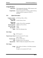
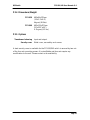
BSS Audio
V 3.0
FCS-930/960 User Manual v3.0
JMK
14th October 1998
FCS-930/960
User Manual
This equipment has been tested and found to comply with the following European and
international Standards for Electromagnetic Compatibility and Electrical Safety:
Radiated Emissions (EU):
RF Immunity (EU):
EN55013
EN50082/1
Mains Disturbance (EU):
Electrical Safety (EU):
Radiated Emissions (USA):
Electrical Safety (USA):
Electrical Safety (CAN):
EN61000/3/2
EN60065
FCC part 15 Class B
UL813/ETL
UL813/ETLc
(1990) Associated Equipment
(1992) RF Immunity, Fast Transients
ESD
(1995)
(1993)
(1996) Commercial Audio Equipment
(1996) Commercial Audio Equipment
IMPORTANT SAFETY INFORMATION
DO NOT REMOVE COVERS. NO USER SERVICEABLE PARTS INSIDE, REFER SERVICING
TO QUALIFIED SERVICE PERSONNEL. THIS EQUIPMENT MUST BE EARTHED.
IT SHOULD NOT BE NECESSARY TO REMOVE ANY PROTECTIVE EARTH OR SIGNAL
CABLE SHIELD CONNECTIONS TO PREVENT GROUND LOOPS. ANY SUCH
DISCONNECTIONS ARE OUTSIDE THE RECOMMENDED PRACTISE OF BSS AUDIO
AND WILL RENDER ANY EMC OR SAFETY CERTIFICATION VOID.
For continued compliance with international EMC legislation ensure that all input and
output cables are wired with the cable screen connected to Pin 1 of the XLR connectors.
The input XLR Pin 1 is connected to the chassis via a low value capacitor, providing high
immunity from ground loops whilst ensuring good EMC performance.
We have written this manual with the aim of helping installers and sound engineers to get
to grips with the FCS-930/960 and obtain its maximum capability. If you are new to BSS
products, we recommend that you begin at the start of the manual.
We welcome any comments or questions regarding the FCS-930/960 or other BSS
products, and you may contact us at the address or World Wide Web site given in
the warranty section.
Page 1
BSS Audio
FCS-930/960 User Manual v3.0
Contents
1 Mechanical Installation
3
2 Mains power connection
3
3 Introduction
4
4 Unpacking
5
5 Audio connections
5
5.1 Balanced wiring
5.2 Unbalanced wiring
5.3 Ground loop control
5.4 Powering up
5
5
6
6
6 Control descriptions
6
6.1 Front panel
6.2 Rear panel
7
7
7 Using the FCS-930/960
8
7.1 Normal Mode
7.2 Fine mode
7.3 High pass filter
7.4 Gain control peak LED
9
9
9
9
8 Filter shape and interactive effects
10
9 Service section
11
9.1 Chassis/0V removal
9.2 Transient suppressor replacement
9.3 Optional balancing transformer fitting
11
12
12
10 Warranty Information
13
11 Specifications
14
11.1 System Performance
11.2 Filters
11.3 Power
11.4 Dimensions/Weight
11.5 Options
14
14
14
15
15
Page 2
BSS Audio
FCS-930/960 User Manual v3.0
1 Mechanical Installation
A vertical rack space of 2U (3.5", 88.9mm) for the FCS-930, and 3U (5.25",
133.35mm) for the FCS-960 is required. You must support the unit at its rear by
additional bracing or shelving if it is to be used in a transportable system. Failure to
do so will impair reliability and invalidate the warranty. Adequate ventilation must
be provided for by allowing sufficient room around the sides and rear of the unit to
ensure free circulation of air. Forced cooling is not required. The front of the unit
should not be exposed to long term direct sunlight as this can have a detrimental
long term effect on the control knobs.
The internal power supply transformer is mounted on the case rear. After a period
of time in an enclosure, the metal case will feel hot to the touch, but this is quite
normal and should not be a cause for alarm.
2 Mains power connection
WARNING! THIS APPLIANCE MUST BE EARTHED.
The FCS-930/960 must always be connected to a 3-wire earthed AC outlet. The
rack framework must also be connected to the same grounding circuit. The unit
must NOT be operated unless the power cables' EARTH (ground) wire is properly
terminated - this is important for personal safety as well as for proper control over
the system grounding. The FCS-930/960 has electronically balanced audio
connections and does not need disconnection of any safety earth for the avoidance
of hum loops.
The wires in the mains lead are colour coded in accordance with the following
code.
Green and Yellow......Earth
Blue......Neutral
Brown......Live
Those units supplied to the North American market will have an integral moulded
3 pin connector which is provided to satisfy required local standards.
IMPORTANT: The FCS-930/960 is designed to use 50/60Hz AC power in one of
the two voltage ranges, selectable with the mains voltage selector switch on the
rear of the unit. It is vital that the position of this switch is checked BEFORE initial
power up to ensure that it matches the local mains supply. Acceptable input AC
supply voltages range from:
115V switch position
-
90V to 132V
230V switch position
-
190V to 264V
The application of voltages outside these ranges may cause permanent damage or
erratic operation of the unit, and will invalidate the warranty.
Page 3
BSS Audio
FCS-930/960 User Manual v3.0
IMPORTANT: The mains fuse carrier on the rear of the unit must be fitted with the
correct type and rating of fuse, depending on the position of the mains voltage
selector switch:
115V switch position
-
T250mA fuse
230V switch position
-
T200mA fuse
In the unlikely event of the mains fuse failing without good reason, please refer to
section 9.2; Transient Suppressor Replacement.
3 Introduction
The FCS-930 and FCS-960 are dual mode graphic equalisers; each channel
featuring 30 filter bands spaced at the standard one third octave ISO frequency
centres, spanning 25Hz at the low frequency end up to 20kHz at the high
frequency end. The FCS-930 is a single channel unit, while the FCS-960 has two
independent channels that may be used as a stereo pair.
The filter topology used is not based on the more common gyrator principle, but
rather on a band pass multiple feedback technique which makes less demands on
the integrated circuits at high frequencies. The resulting excellent sounding circuit
also offers good long term stability and a constant Q response. This is also
configurable to allow you to select the optimum response shape, dependent on
whether you wish to provide gentle program sweetening, or precise single
frequency tuning, such as notching room resonances and feedback suppression.
Some of the features available within the FCS-930/960 are:
•
Long 45mm fader travel for precise adjustment and control.
•
Centre detented fader with electrical centre tap for true 0dB setting.
•
Advanced constant Q filter topology for improved accuracy at all fader
settings and excellent sonic transparency. Selectable normal or fine filter response.
•
Continuously variable high pass filter, with bypass switch.
•
Gain control for system loudness normalisation.
•
Peak clip LED to give advance warning of signal overload.
•
Channel bypass selection and power fail bypass by relays.
•
Electronically balanced inputs and outputs.
•
Proprietary design fader knob provides positive feel with ample finger room,
virtually eliminates visual parallax errors even under low ambient light conditions
•
Optional internal input and output transformer balancing.
Page 4
BSS Audio
FCS-930/960 User Manual v3.0
4 Unpacking
As part of the BSS system of quality control, we check every product carefully
before packing to ensure that it reaches you in flawless condition.
Before you go any further, please check the unit for any physical damage and
retain the shipping carton and all relevant packing materials for use, should the
unit need returning.
In the event that damage has occurred, please notify your dealer immediately, so
that a written claim to cover the damages can be initiated. Refer to section 11.0;
Warranty Information, for more info on the warranty, and also to record your
dealer details.
5 Audio connections
The FCS-930/960 audio inputs are RFI filtered and electronically balanced, with
the outputs electronically balanced and floating. They are designed to operate at
any signal level up to +20dBu and will drive into loads of 600 ohms or greater.
They will be ‘fuss free’, regardless of your installation’s complexity.
Note that pin 1 of the input XLR is not connected to ground.
5.1 Balanced wiring
Whether your system is wired to a ‘pin 3 hot’ or a ‘pin 2 hot’ convention will not
matter as long as your wiring to both the input and output 3 pin XLR connectors
are the same. As is common with all other BSS equipment of this type, we follow
the convention of ‘screen goes forward with the signal’. Input cable screening
therefore needs to be derived from the signal source end as pin 1 is ground lifted
for the inputs. You should use high quality audio cable with 2 cores + screen for
low noise and reliability, and to sidestep potential problems.
5.2 Unbalanced wiring
If the equipment driving the FCS-930/960 has only unbalanced outputs then you
will need to add a wire jumper such that the screen connection on Pin 1 of the XLR
is shorted to either Pin 2 OR Pin 3, depending on the wiring convention of the
unbalanced equipment.
If the equipment being connected to the FCS-930/960 outputs has only unbalanced
inputs, then we recommend that you still use a balanced (i.e. 2 core shielded)
cable. The interconnecting cable should have it’s screen grounded by pin 1 of the
FCS-930/960 output, the pin 3 output should be connected to the unbalanced
input 0v ground, and the pin 2 output should be connected to the live input. There
should be no connection between the cable screen and 0v/chassis ground
connection of the unbalanced equipment. Strict adherence to this will help to
Page 5
BSS Audio
FCS-930/960 User Manual v3.0
eliminate potential ground loop hums by removing signal currents from the cable
screen.
5.3 Ground loop control
Strict adherence to the wiring conventions noted above within a fully balanced
signal system will yield the best possible results with none of the problems
normally associated with interconnected audio equipment.
Wherever possible, cable screens should not be connected to any signal pin, but
rather left to perform a cable shielding function only.
Where it is not possible to control all of the external cabling, it might become
necessary to have the internal electronic ground of your unit separated from the
case safety ground. Provision is made internally within the FCS-930/960 to
separate these two grounds at a convenient point, or to add a suitable impedance
network as part of a house system requirement.
Please refer to section 9.1; Chassis/0v Removal for information on this procedure.
Under no circumstances should the safety ground wire be removed from the
mains AC power connector as an interim measure to achieve similar results.
5.4 Powering up
When the FCS-930/960 is switched on by operating the power on-off switch
located on the rear panel, the front panel LED showing the normal MODE will be
illuminated. This indicates to you that the internal power supply circuitry is
functioning correctly. The unit will also be in it’s bypass mode. Should you
subsequently have the EQ IN switch selected before power up, there will be a
slight delay before the bypass relays operate, to allow time for the internal circuitry
to settle down. This ensures a silent power up without danger of causing damage to
other equipment connected to the units outputs.
Page 6
BSS Audio
FCS-930/960 User Manual v3.0
6 Control descriptions
6.1 Front panel
Filter boost and cut fader control. Move this fader to vary the amount of boost or
cut required, at the frequency of the fader. It has a centre detent and electrical
centre tap which guarantees you a precise ‘flat’ setting in the central position.
Gain adjustment control with +/- 10dB of range. Adjust this if you wish to balance
the equalised sound with the general loudness of the unequalised sound. The
control has no effect on the bypassed signal level.
EQ IN selector. Push to select equalisation, release to bypass. The LED indicator
illuminates to confirm the equalisation in status. Bypass is achieved by using relays
which ensures a complete equipment bypass.
Peak LED indicator gives you advance warning of possible circuit overload by
illuminating 2dB before actual clip. It is monitoring signals both before and after
the GAIN control [2] and will operate should any one of them exceed the danger
level. Should this occur, then the signal level entering the FCS-930/960 will need
to be reduced in level. If you are using large amounts of extra gain from the GAIN
control then this can be backed off, but any previous balance achieved will then
be lost.
Operate this MODE switch to change the filter bandwidth. This is confirmed by the
appropriate LED illuminating, with higher selectivity, fine mode being active with
the switch depressed. In general you should use the normal mode (switch out), for
all general sweetening work. Select the fine mode for specialised room/speaker
notching and feedback control applications.
Frequency control for the high pass filter. This allows you to roll off the low
frequency energy of the program should it not be required. It is fully adjustable
from 20Hz to 250Hz.
High pass filter switch selects whether the filter is in or out of circuit. Pressing the
switch selects the filter, confirmed by the LED illuminating.
6.2 Rear panel
Mains power fuse is 20mm long and rated at T250mA for 120V voltage setting and
T200mA for the 240V voltage setting. For continued protection, please always
replace this fuse with the correct value.
Mains power switch.
Mains voltage selector switch allows operation from 90V-130V or 190V-250V.
Mains power inlet.
Page 7
BSS Audio
FCS-930/960 User Manual v3.0
Electronically balanced and floating output. Maximum output is +20dBu into
600W. Transformer balancing is available as an option.
The pin connections are:
Pin 1
Ground/chassis.
Pin 2
Hot (+).
Pin 3
Cold (-).
Electronically balanced input. Maximum input is +20dBu into 10kW. Transformer
balancing is available as an option.
The pin connections are:
Pin 1
Open circuit/no connection.
Pin 2
Hot (+).
Pin 3
Cold (-).
Take note of the ground break on Pin 1. As with all BSS products, the convention is
‘screen goes forward with the signal’, giving a useful ground loop break point at
the input connector. The audio lead connected to the input must therefore have its
screen grounded at the signal source end. When using a fully balanced system,
either Pin 2 or Pin 3 may be the HOT terminal.
7 Using the FCS-930/960
The FCS-930/960 Graphic equaliser is the result of a detailed study of sound
engineers and contractors requirements plus many hours of voice and music
program listening tests to carefully optimise the benefits of controlling equalisation
in this ergonomically efficient and familiar manner.
The filter sets chosen are arranged in the alternate summing mode to reduce
interaction, and utilise a multiple-feedback band-pass topology rather than the
more generally used gyrator topology. This assures excellent high frequency fidelity
by placing less demands on the associated electronics. The resulting filter shape is
‘constant Q’ giving a constant bandwidth regardless of the amount of boost or cut
selected. This produces consistent selectivity over the whole range of fader
movement.
The extra long 45mm faders are centre detented for accurate zero setting, as well
as being centre tapped. This electrical centre tap, which is grounded, ensures each
filter set is properly removed from the circuit at the faders central position. This will
give you added confidence during use, as well as reassurance that, if a filter is not
being used, it is absent from the signal path.
Analysis has shown that the filter shape requirements depend to a large extent on
the final application for the equaliser and for this reason the FCS-930/960 is
provided with a MODE selector which re configures the filter sets.
Page 8
BSS Audio
FCS-930/960 User Manual v3.0
7.1 Normal Mode
Here the Q value of the filter is set to allow groups of faders to be set in a pattern
which represents fairly closely the actual amplitude response obtained. The
combining effect is smooth whilst still retaining a degree of selectivity normally
associated with a graphic equaliser. The constant Q design allows predictable and
precise control over the whole range of fader movement.
This Normal mode would be used for all sweetening type of work where boosts
and cuts are combined to provide an overall smooth contouring response.
7.2 Fine mode
Here the filters are reconfigured to offer a higher Q value, and hence produce less
adjacent filter interaction. This requirement is consistent with applications where
high selectivity is required such as for correcting room resonances and where a
number of notches are required to be inserted to avoid feedback. Again the filters
produce a constant Q shape which allows high selectivity for small amounts of cut
or boost. A feature hard to realise on many other graphic equalisers. In general you
would use this mode where amplitude cuts are primarily being introduced. It still
however, has many applications for sweetening work as the combining response is
still acceptably ripple free.
7.3 High pass filter
This third order variable filter sweeps from 20Hz to 250Hz at 18dB/oct and
provides extra equalisation in applications where precise control is required on
the low frequency energy within a system. This can be required for protecting
loudspeakers from excessive cone excursion beyond their design limits, for
optimising amplifier headroom in passively crossed-over loudspeaker systems by
limiting wasted power at low frequencies, or for increasing intelligibility in mainly
voice based applications. Press the associated switch to select the
filter, and the LED illuminates in confirmation. De-selecting the function removes
the filter from the signal path completely.
7.4 Gain control peak LED
This control is incorporated within the filter sections offering the facility to balance
the overall sound level, after setting the required equalisation. It offers a range of
±10dB, the centre position being 0dB unity gain.
When the EQ IN switch is released (equalisation bypassed), the GAIN control is
also bypassed and does not affect the output signal level. This allows proper A/B
comparisons to be made of the program signal as the EQ IN switch is operated.
The PEAK LED indicator monitors a number of points within the circuitry and will
indicate when the signal at any of the monitored points reaches within 2dB of clip.
Page 9
BSS Audio
FCS-930/960 User Manual v3.0
This is only likely to occur if the input signal to the unit is quite large and
substantial boost equalisation is being used. In either case the input signal to the
FCS-930/960 needs to be reduced accordingly. Should you be using large amounts
of GAIN then this could also cause the PEAK LED to indicate and suitable
correction can be applied by backing-off the GAIN control accordingly.
8 Filter shape and interactive effects
Graphic equalisers have tremendous value in their ability to modify the amplitude
response of a sound system. They have become the most widely used type of
equaliser product for the general sweetening of a sound system, as well as for more
precise work in helping to remove unwanted resonances in a reverberant room or
removing feedback in stage monitoring systems. Their advantages lie with the
visual picture obtained by the fader positions in representing the modifications
made to the frequency response, and with the reciprocal nature of the boost and
cut effect. Their disadvantages lie in having only certain fixed frequencies
available, and with the interaction effect of one fader on its adjacent fader. The
pictorial view of a modified amplitude response as shown by the fader positions is
an ‘idealised’ one. Each filter has a predetermined shape, defined by its Q value
and design topology and the actual result obtained will not necessarily be a
smooth curve, as depicted by the fader knob positions, but rather one which is
defined by the overall shape of each filter and how it combines with its adjacent
filter. For the application of general sweetening where groups of faders will be
moved to form a particular shape, a good combining effect is desired to avoid a
number of humps appearing in the amplitude response. This requires a particular
filter design which is not compatible with that needed when greater selectivity is
required for room tuning and feedback suppression. Moreover, on some graphic
equaliser designs, the Q value will vary as the amount of boost or cut is varied,
further adding to the complication.
On the FCS-930/960 we have carefully optimised the design to account for these
effects. Adding the dual mode feature allows us to re configure the filter shapes to
accommodate the different applications. Using a constant Q filter design removes
the width variation with boost and cut, thus allowing more selectivity at low levels
of boost and cut.
When adjacent filters are adjusted there will always be some interaction affect, and
the degree that is required is dependent on the application.
The FCS-930/960 in its Normal mode shows very smooth combining properties
with almost complete absence of ripple, even at full boost. For the Fine mode
precise selectivity and minimal interaction is achieved at half boost, whilst for full
boost combining ripple is minimal.
Page 10
BSS Audio
FCS-930/960 User Manual v3.0
!!! WARNING - Refer all servicing to qualified service personnel !!!
Risk of electric shock if the unit is opened.
BSS Audio accepts no responsibility for injury
subsequent to opening of the unit.
9 Service section
9.1 Chassis/0V removal
The FCS-930/960 has the signal 0v ground connected to the metal chassis, which
in turn is connected to the safety ground. In the unlikely event that you need to
remove this link, or if you need to add a small impedance to reduce earth loop
currents, then proceed as follows.
Since both the audio inputs and outputs are wired fully balanced we would suggest
that you fully recheck all audio wiring for correctness, prior to proceeding.
Under no circumstances should the incoming safety ground wire be disconnected
from the power line cord, or from the internal chassis connection as an alternative
to this procedure.
1
Disconnect the mains power cord and remove the unit’s top cover.
2
Locate the link on the printed circuit board adjacent to the rear PCB fixing
bracket marked ‘GROUND LIFT’.
3
Remove this link.
The signal/0v ground is now isolated from the chassis.
The other link, marked ‘PIN 1 TO CHASSIS’ is connecting the output XLR pin 1
connections to chassis. Under no circumstances is it recommended that you
remove this link.
Page 11
BSS Audio
FCS-930/960 User Manual v3.0
!!! WARNING - Refer all servicing to qualified service personnel !!!
Risk of electric shock if the unit is opened.
BSS Audio accepts no responsibility for injury
subsequent to opening of the unit.
9.2 Transient suppressor replacement
The primary of the mains transformer within the FCS-930/960 is protected against
high voltage spike interference by two voltage dependent resistors. These provide a
short circuit to voltage peaks in excess of their maximum rating.
Should the FCS-930/960 be inadvertently connected to 3 phase line/line voltages,
or to 240V when selected to 120V, or any other incorrect voltage, these
suppressors are likely to fail in a protective short circuit mode. This will be
demonstrated by repeated mains fuse failure when powering up the unit.
Even in this case of extreme overvoltage, the FCS-930/960 are protected against
failure, and the simple removal of these suppressors will allow the unit to be used
again. However, it is important that they are replaced as soon as possible to ensure
continued protection. Ensure that the mains power is disconnected from the unit
before the lid is removed, and the suppressors are removed.
9.3 Optional balancing transformer fitting
Provision is made internally to fit balancing transformers to both the electronically
balanced inputs and outputs (Refer to the spare parts information sheet for
reference codes for these transformers).
The transformers are easily fitted onto the printed circuit board adjacent to the
respective output connectors. Please ensure correct orientation and removal of
links:
LINK REMOVAL
CHN 1
CHN 2 (FCS-960 only)
INPUT TX
1, 2
7, 8
OUTPUT TX
3, 4
5, 6
Page 12
BSS Audio
FCS-930/960 User Manual v3.0
10 Warranty Information
When sold to an end user by BSS Audio or a BSS Audio Authorised Reseller, this
unit is warranted by the seller to the purchaser against defects in workmanship and
the materials used in its manufacture for a period of one year from the date of sale.
Faults arising from misuse, unauthorised modifications or accidents are not
covered under this warranty. No other warranty is expressed or implied.
If the unit is faulty it should be sent to the seller of the equipment, in its original
packaging with shipping prepaid. The unit will be returned to you when the repair
has been completed. If the unit was purchased in the European Union, you may, as
an alternative, return the unit to any other BSS distributor in the European Union.
You should include a statement listing the faults found. The unit’s serial number
must be quoted in all correspondence relating to a claim.
We recommend that you record your purchase information here for future
reference.
Dealer Name:
Dealer Address:
Post/Zip Code:
Dealer Phone No.:
Dealer Contact Name:
Invoice/Receipt No.:
Date of Purchase:
Unit Serial Number:
In keeping with our policy of continued improvement, BSS Audio reserves the right
to alter specifications without prior notice.
The FCS-930/960 was designed and developed by BSS Audio, Hertfordshire,
England.
Phone (+44) (0)1707 660667. Fax (+44) (0)1707 660755.
World Wide Web address: http://www.bss.co.uk
Page 13
BSS Audio
FCS-930/960 User Manual v3.0
11 Specifications
11.1
Input Section
10kΩ electronically balanced, +20dBu maximum input
level via XLR3-31 or equivalent.
Output Section
Electronically balanced and floating, capable of driving
+20dBu into 600Ω or greater via XLR3-32 or
equivalent.
System Performance
Frequency response
THD at +4dBu
(faders flat)
Output noise
(faders flat)
±0.25dB from 20Hz to 20kHz
<0.005% 22Hz to 22kHz
<-90dBu, 22Hz to 22kHz unweighted
Channel separation
>80dB from 22Hz to 22kHz
Gain control range
±10dB
Peak indicator
Bypass
+18dBu
Passive fail-safe bypass relay
11.2 Filters
Type
MFB Constant Q
Frequencies, per channel 30 off on 1/3 octave ISO centres
25Hz to 20kHz
Boost/cut range
Mode
High pass filter
Nominal ±10dB. Note 1
Selectable normal or fine response
18dB/Oct Butterworth sweepable 20Hz to 250Hz
11.3 Power
Voltage
30VA 50-60Hz, 90-120Vac or 190-250Vac selectable
externally.
2m power cord connected via IEC socket.
Page 14
BSS Audio
FCS-930/960 User Manual v3.0
11.4 Dimensions/Weight
FCS-930
482x89x227mm.
(19"x3.5"x8.9")
4kg net, (8.8lbs).
FCS-960
482x132x227mm
(19"x5.25"x8.9")
4.3kg net, (9.5 lbs)
11.5 Options
Transformer balancing
Security cover
Input and output.
Metal cover, secured by rack screws.
A steel security cover is available for the FCS-930/960 which is secured by two out
of the four rack mounting screws. It is retrofittable and does not require any
modification to the unit. Please contact us for availability.
Page 15