1
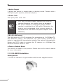
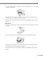
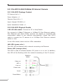
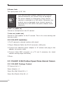
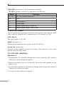
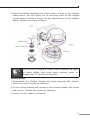
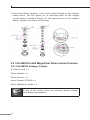
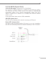
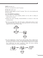
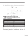
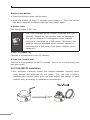
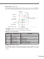
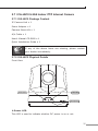
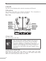
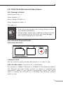
H.264
Internet Camera
&
Internet Video Server
ICA-HM230 / ICA-H312 / ICA-H651 / ICA-HM130 /
ICA-HM135 / ICA-HM350 / ICA-H610 / IVS-H120
Quick Installation Guide
Version 1.2
Table of Contents
Chapter 1. Introduction............................................................................. 4
1.1 Before Installation....................................................................... 4
1.2 System Requirements . ............................................................... 4
Chapter 2. Physical Description and Installation.......................................... 5
2.1 ICA-HM230 H.264 Mega-Pixel CMOS Pan / Tilt Internet Camera...... 5
2.1.1 ICA-HM230 Package Content............................................... 5
2.1.2 ICA-HM230 Physical Details................................................. 5
2.1.3 ICA-HM230 Installation........................................................ 6
2.2 ICA-H312 H.264 25-Meter IR Internet Camera.............................. 8
2.2.1 ICA-H312 Package Content.................................................. 8
2.2.2 ICA-H312 Physical Details.................................................... 8
2.2.3 ICA-H312 Installation........................................................ 10
2.3 ICA-H651 H.264 Outdoor Speed Dome Internet Camera.............. 10
2.3.1 ICA-H651 Package Content................................................ 10
2.3.2 ICA-H651 Physical Details.................................................. 11
2.3.3 ICA-H651 Installation........................................................ 12
2.4 ICA-HM130 H.264 Mega-Pixel Dome Internet Camera.................. 14
2.4.1 ICA-HM130 Package Content............................................. 14
2.4.2 ICA-HM130 Physical Details............................................... 15
2.4.3 ICA-HM130 Installation...................................................... 17
2.5 ICA-HM135 H.264 Mega-Pixel 20M IR Vandal Proof IP Dome........ 18
2.5.1 ICA-HM135 Package Content............................................. 18
2.5.2 ICA-HM135 Physical Details............................................... 18
2.5.3 ICA-HM135 Installation...................................................... 20
2.6 ICA-HM350 H.264 Mega-Pixel 30M Outdoor IR Internet Camera......22
2.6.1 ICA-HM350 Package Content............................................. 22
2.6.2 ICA-HM350 Physical Details............................................... 22
2.6.3 ICA-HM350 Installation...................................................... 24
2.7 ICA-H610 H.264 Indoor PTZ Internet Camera.............................. 25
2.7.1 ICA-H610 Package Content................................................ 25
2.7.2 ICA-H610 Physical Details.................................................. 25
2.7.3 ICA-H610 Installation........................................................ 27
2.8 IVS-H120 H.264 Internet Video Server....................................... 29
2.8.1 Package Content............................................................... 29
2.8.2 IVS-H120 Physical Details ................................................ 29
2.8.3 IVS-H120 Installation........................................................ 31
Chapter 3. Camera Windows Utility.......................................................... 32
Further Information................................................................................ 35
Chapter 1. Introduction
Thank you for purchasing the PLANET H.264 IP Camera. It is versatile
and high image solution of surveillance application for day and night.
The PLANET IP Camera is also a stand-alone camera system with a
built-in processor and web server that provides highest quality video
and system performance.
The PLANET IP Camera support Multi-Profile function can stands for
simultaneously video streams. These Network Cameras can generate
H.264, MPEG-4 and M-JPEG streaming simultaneously to different
clients. Moreover, the resolution can be different from one client to
another. This state-of-art design is considerable to fit in various network
environments.
1.1 Before Installation
Before installation, please be sure to read this quick installation guide
and user’s manual (CD) carefully to complete machine installation.
This guide shows how to quick set up the three cameras, unless model
name specified terms “IP Camera” will be used for these three models.
1.2 System Requirements
CPU
Intel® Core2 Duo E5300 2.6GHz
RAM
1 GB
Video RAM
128MB
Display Chip
nVIDIA GeForce 8500GT
ATI Radeon HD 4350
Display Resolution
1024 x 768 24bits
Operating System
Windows 2000 SP4 / Windows XP Pro
SP2 / Windows 2003 / Vista
DirectX
9.0c or above
Required space for installation
100 MB
Recommended HD free space
160 GB
Network
Wired Ethernet 100Base-TX
Chapter 2. Physical Description and Installation
2.1 ICA-HM230 H.264 Mega-Pixel CMOS Pan / Tilt
Internet Camera
2.1.1 ICA-HM230 Package Content
IP Camera Unit x 1
Power Adapter x 1
Camera Mount Kit x 1
User’s Manual CD-ROM x 1
Quick Installation Guide x 1
Note
If any of the above items are missing, please contact
your dealer immediately.
2.1.2 ICA-HM230 Physical Details
Audio Output
RJ-45
Reset Button
Power Jack
1.Audio Output
It allows this device to output audio or alerting sound. Connect with a
3.5Ø phone jack speaker (external adaptor).
2.Power Jack
The input power is DC 12V.
Note
1. Only use the power adapter supplied with internet
camera Otherwise, the product may be damaged.
2. The power adapter is unnecessary when internet
camera is connected to a PoE switch. Otherwise, the
product may be damaged when internet camera is
connected to a PoE switch and power adapter simultaneously.
3.RJ-45 LAN Socket
The LAN socket is a RJ-45 connector for connections to 10/100Base-TX
Fast Ethernet cabling. This Ethernet port built N-Way protocol can
detect or negotiate the transmission speed of the network automatically.
Please use CAT-5 cable to connect the IP camera to a 100Mbps Fast
Ethernet network switch or hub.
4.Factory Default Reset
This button is hidden in the pinhole. Please refer to the user’s manual
for more information.
2.1.3 ICA-HM230 Installation
Ceiling Mount
1.Fix the IP camera to L-type bracket with the two supplied screws.
2.Fix the bracket and IP camera to the ceiling using two holly wall
anchors and screws.
3.Connect the LAN cable to a switch or hub. When this switch/hub is a
PoE device, you can ignore the next step.
4.Connect DC-Jack to the with the bundle power adapter power source.
5.Done.
Wall Mount
1.Fix the L-type bracket to the wall using two holly wall anchors and
screws.
2.Fix the IP camera to L-type bracket with the two supplied screws.
3.Connect the LAN cable to a switch or hub. When this switch/hub is a
PoE device, you can ignore the next step.
4.Connect DC-Jack to the with the bundle power adapter power source.
5.Done.
2.2 ICA-H312 H.264 25-Meter IR Internet Camera
2.2.1 ICA-H312 Package Content
IP Camera Unit x 1
Power Adapter x 1
Camera Mount Kit x 1
User’s Manual CD-ROM x 1
Quick Installation Guide x 1
2.2.2 ICA-H312 Physical Details
1.RJ-45 LAN socket: Connect to PC or Hub/Switch.
For connect to 10Base-T Ethernet or 100Base-TX Fast Ethernet cabling.
This Ethernet port built N-Way protocol can detect or negotiate the
transmission speed of the network automatically. Please use CAT-5
cable to connect the IP camera to a 100Mbps Fast Ethernet network
switch or hub.
In the LAN socket, there are two LEDs embedded:
LAN LED (green color)
This LED will be flashing while network accessing via Ethernet.
Power LED (orange color)
This LED is used to indicate whether DC power is on or not. In addition,
this LED will be flashing while the network accessing of the IP camera.
RS485 &
DI/DO
Video out
MIC in
Line out
Power Jack
RJ-45
Reset Button
2.RS-485: Connect to a local keyboard controller.
DI/DO: Connect to sensor in and alarm out devices.
Cable for I/O connectors:
Name
Cable Color
Function
DC 12V
Brown/White
DC 12V (50mA maximum)
GND
Blue/White
GND
D+
Purple/White
RS485 data +
D-
Gray
RS485 data -
DI
Green/White
Digital signal input
DO
Orange/White
Digital signal output
3.Video out (BNC Connector)
The Network Camera also provides composite video output. User can
use BNC video cable to connect the Network Camera with a TV monitor
or VCR.
4.Reset Button
This button is used to restore the all factory default settings.
Sometimes restarting the device will make the system back to a normal
state. However, if the system still got problems after restart, user can
restore the factory default settings and install it again.
Restore the device:
a.Press the button down continuously.
b.Hold the button at least 5 seconds and release it. Then the device
has been restored to default settings and reboot again.
5.Power Jack
The input power is DC 12V.
Note
1. Only use the power adapter supplied with internet
camera Otherwise, the product may be damaged.
2. The power adapter is unnecessary when internet
camera is connected to a PoE switch. Otherwise, the
product may be damaged when internet camera is
connected to a PoE switch and power adapter simultaneously.
6.MIC in (audio in)
Connect a microphone to the IP camera.
7.Line out (audio out)
Connect a loud speaker to the IP camera. This is for voice alerting and
two-way audio.
2.2.3 ICA-H312 Installation
1.Fix IP camera to desired location with stand.
2.Plug-in Ethernet Cable into RJ-45 connector (LAN port).
3.Connect the attached power adapter to IP camera and plug-in this
adapter into power outlet.
4.Connect Video BNC connector to a TV set if necessary (to check
camera viewing angle and focus).
5.Done.
2.3 ICA-H651 H.264 Outdoor Speed Dome Internet Camera
2.3.1 ICA-H651 Package Content
IP Camera Unit x 1
Power Adapter x 1
Power Box Wall Mount Kit x 1
Power Box Electric Wire Kit x 1
10
Camera Bracket Screws Kit x 1
Waterproof Strip x 1
Terminal Block x 2
Video and Audio Cable x 3
Zoom Cable x 1
User’s Manual CD-ROM x 1
Quick Installation Guide x 1
Note
If any of the above items are missing, please contact
your dealer immediately
2.3.2 ICA-H651 Physical Details
1.RJ-45 LAN socket: Connect to PC or Hub/Switch.
For connects to 10Base-T Ethernet or 100Base-TX Fast Ethernet
cabling. This Ethernet port built N-Way protocol can detect or negotiate
the transmission speed of the network automatically. Please use CAT-5
cable to connect the IP camera to a 100Mbps Fast Ethernet network
switch or hub. The LAN cable is wired well for user’s easy installation.
MIC in
Line out 12VDC
DI/DO
RS485 Video Out AC 24V in
11
2.RS-485: Connect to a local keyboard controller.
DI/DO: Connect to sensor in and alarm out devices.
Name
Function
DC 12V
DC 12V (60mA maximum)
GND
GND
D+
RS485 data +
D-
RS485 data -
DI
Digital signal input (Digital In)
DO
Digital signal output (Alarm Out)
3.Local Video output
The IP camera also provides composite video output. User can use BNC
video cable to connect the IP camera with a TV monitor or VCR.
4.AC 24V in
The input power is AC 24V.
5.MIC in (audio in)
Connect a microphone input source to the IP camera.
6.Line out (audio out)
Connect a loud speaker to the IP camera. This function is for voice
alerting and two-way audio.
2.3.3 ICA-H651 Installation
Wall Mount
1.Disassemble the Outdoor Flange and dome housing with wrench.
Mount the dome housing as figure.
2.Mount the power box on a solid wall. Mount the wall bracket on the
power box.
3.Fix the wall bracket to the outdoor flange with screws and wrench.
Tighten the screws as figure.
4.Connect all the cables as required.
12
5.Mount the Safety Hanging-Lock of the outdoor flange on the outdoor
speed dome. Aim the guide pin of mounting base at the longest
curved chute of outdoor flange. Fix the speed dome on the outdoor
flange. Tighten the screw as figure.
Note
Due to the IP camera is heavy, while installing, be ware
of object falling that could injure workers below or
damage the IP camera permanently.
Ceiling Mount
1.Disassemble the Outdoor Flange and dome housing with wrench.
Mount the dome housing as following.
2.Fix the ceiling bracket and connect it with outdoor flange with screws
and wrench. Tighten the screws as following.
3.Connect all the cables as required.
13
4.Mount the Safety Hanging- Lock of the outdoor flange on the outdoor
speed dome. Aim the guide pin of mounting base at the longest
curved chute of outdoor flange. Fix the speed dome on the outdoor
flange. Tighten the screw as following.
2.4 ICA-HM130 H.264 Mega-Pixel Dome Internet Camera
2.4.1 ICA-HM130 Package Content
IP Camera Unit x 1
Power Adapter x 1
Mount Screws x 4
User’s Manual CD-ROM x 1
Quick Installation Guide x 1
Note
14
If any of the above items are missing, please contact
your dealer immediately.
2.4.2 ICA-HM130 Physical Details
1.RJ-45 LAN socket: Connect to PC or Hub/Switch.
For connect to 10Base-T Ethernet or 100Base-TX Fast Ethernet cabling.
This Ethernet port built N-Way protocol can detect or negotiate the
transmission speed of the network automatically. Please use CAT-5
cable to connect the IP camera to a 100Mbps Fast Ethernet network
switch or hub.
In the LAN socket, there are two LEDs embedded:
LAN LED (green color)
This LED will be flashing while network accessing via Ethernet.
Power LED (orange color)
This LED is used to indicate whether DC power is on or not. In addition,
this LED will be flashing while the network accessing of the IP camera.
RS485 &
DI/DO
MIC in
Line out
Power Jack
RJ-45
Reset Button
15
2.RS-485: Connect to a local keyboard controller.
DI/DO: Connect to sensor in and alarm out devices.
Cable for I/O connectors:
Name
Cable Color
Function
DC 12V
Brown/White
DC 12V (50mA maximum)
GND
Blue/White
GND
D+
Purple/White
RS485 data +
D-
Gray
RS485 data -
DI
Green/White
Digital signal input
DO
Orange/White
Digital signal output
3.Reset Button
This button is used to restore the all factory default settings.
Sometimes restarting the device will make the system back to a normal
state. However, if the system still got problems after restart, user can
restore the factory default settings and install it again.
Restore the device:
a.Press the button down continuously.
b.Hold the button at least 5 seconds and release it. Then the device
has been restored to default settings and reboot again.
4.Power Jack
The input power is DC 12V.
Note
16
1. Only use the power adapter supplied with internet
camera Otherwise, the product may be damaged.
2. The power adapter is unnecessary when internet
camera is connected to a PoE switch. Otherwise, the
product may be damaged when internet camera is
connected to a PoE switch and power adapter simultaneously.
5.MIC in (audio in)
Connect a microphone to the IP camera.
6.Line out (audio out)
Connect a loud speaker to the IP camera. This is for voice alerting and
two-way audio.
2.4.3 ICA-HM130 Installation
1.Please select the most suitable position on the wall or ceiling to
install the IP camera.
2.Rotate the dome housing counterclockwise to remove it from the
mounting base.
3.Set the mounting base onto the wall or ceiling and center it over
the mounting hole, using the two retaining screws for the main body,
supplied by the appurtenance bag.
4.For lens adjustment, move the IP camera body (some model type’s
limits the PCB board to 180° rotational adjustment) and set the focus
by turning the lens to the left or right direction. When the IP camera
focus adjustment has been completed, rotate the dome housing
clockwise to secure it to the mounting base.
17
5.Connect the LAN cable to a switch or hub. When this switch/hub is a
PoE device, you can ignore the next step.
6.Connect Power Jack to the bundled power adapter.
7.Done.
2.5 ICA-HM135 H.264 Mega-Pixel 20M IR Vandal Proof IP
Dome
2.5.1 ICA-HM135 Package Content
IP Camera Unit x 1
Power Adapter x 1
Mount Screws x 4
User’s Manual CD-ROM x 1
Quick Installation Guide x 1
Note
If any of the above items are missing, please contact
your dealer immediately.
2.5.2 ICA-HM135 Physical Details
1.RJ-45 LAN socket: Connect to PC or Hub/Switch.
For connect to 10Base-T Ethernet or 100Base-TX Fast Ethernet cabling.
This Ethernet port built N-Way protocol can detect or negotiate the
transmission speed of the network automatically. Please use CAT-5
cable to connect the IP camera to a 100Mbps Fast Ethernet network
switch or hub.
In the LAN socket, there are two LEDs embedded:
LAN LED (green color)
This LED will be flashing while network accessing via Ethernet.
18
Power LED (orange color)
This LED is used to indicate whether DC power is on or not. In addition,
this LED will be flashing while the network accessing of the IP camera.
RS485 &
DI/DO
MIC in
Line out
Power Jack
RJ-45
Reset Button
2.RS-485: Connect to a local keyboard controller.
DI/DO: Connect to sensor in and alarm out devices.
Cable for I/O connectors:
Name
Cable Color
Function
DC 12V
Brown/White
DC 12V (50mA maximum)
GND
Blue/White
GND
D+
Purple/White
RS485 data +
D-
Gray
RS485 data -
DI
Green/White
Digital signal input
DO
Orange/White
Digital signal output
3.Reset Button
This button is used to restore the all factory default settings.
Sometimes restarting the device will make the system back to a normal
state. However, if the system still got problems after restart, user can
restore the factory default settings and install it again.
19
Restore the device:
a.Press the button down continuously.
b.Hold the button at least 5 seconds and release it. Then the device
has been restored to default settings and reboot again.
4.Power Jack
The input power is DC 12V.
Note
1. ONLY use package power adapter supplied with the
internet. Otherwise, the product may be damaged.
2. The power adapter is unnecessary when internet
camera is connected to a PoE switch. Otherwise, the
product may be damaged when internet camera is
connected to a PoE switch and power adapter simultaneously.
5.MIC in (audio in)
Connect a microphone to the IP camera.
6.Line out (audio out)
Connect a loud speaker to the IP camera. This is for voice alerting and
two-way audio.
2.5.3 ICA-HM135 Installation
1.Use provided L-wrench loosen the tamper-resistant housing cover
(with screws still attached on the cover). The unit has a factory
installed side conduit entry and one may adjust the cables to back
conduit entry according to installation requirement.
20
2.Set the mounting base onto the wall or ceiling and center it over the
mounting hole, using the supplied four retaining screws to secure the
main body.
3.Set the proper image by moving the IP camera body and set the
focus by turning the lens to the left or right direction.
4.When the IP camera focus adjustment has been completed, use the
provided L-wrench to fasten the tamper-resistant housing to the main
body.
5.Vari-Focal operation guide:
Once the picture appears on the monitor, open the cover and adjust the
lens wrench to “NEARÁËFAR”, get the view zoom that you desire,
and then adjust the focus wrench of the lens to obtain the best picture.
After adjustment, tighten both wrenches.
Zoom Adjustment
NEAR
TELE
Focal Adjustment
FAR
WIDE
21
6.Connect the LAN cable to a switch or hub. When this switch/hub is a
PoE device, you can ignore the next step.
7.Connect DC-Jack to the with the bundle power adapter power source.
8.Done.
2.6 ICA-HM350 H.264 Mega-Pixel 30M Outdoor IR
Internet Camera
2.6.1 ICA-HM350 Package Content
IP Camera Unit x 1
Power Adapter x 2
Mount Kit x 1
User’s Manual CD-ROM x 1
Quick Installation Guide x 1
Note
If any of the above items are missing, please contact
your dealer immediately.
2.6.2 ICA-HM350 Physical Details
1.RJ-45 LAN socket: Connect to PC or Hub/Switch.
For connect to 10Base-T Ethernet or 100Base-TX Fast Ethernet cabling.
This Ethernet port built N-Way protocol can detect or negotiate the
transmission speed of the network automatically. Please use CAT-5
cable to connect the IP camera to a 100Mbps Fast Ethernet network
switch or hub.
In the LAN socket, there are two LEDs embedded:
LAN LED (green color)
This LED will be flashing while network accessing via Ethernet.
22
Power LED (orange color)
This LED is used to indicate whether DC power is on or not. In addition,
this LED will be flashing while the network accessing of the IP camera.
RS485 &
DI/DO
Video out
MIC in
Line out
Power Jack
RJ-45
Reset Button
Heater Power Jack
2.RS-485: Connect to a local keyboard controller.
DI/DO: Connect to sensor in and alarm out devices.
Cable for I/O connectors:
Name
Cable Color
Function
DC 12V
Brown/White
DC 12V (50mA maximum)
GND
Blue/White
GND
D+
Purple/White
RS485 data +
D-
Gray
RS485 data -
DI
Green/White
Digital signal input
DO
Orange/White
Digital signal output
3.Video out (BNC Connector):
The Network Camera also provides composite video output. User can
use BNC video cable to connect the Network Camera with a TV monitor
or VCR.
23
4.Reset Button
This button is used to restore the all factory default settings.
Sometimes restarting the device will make the system back to a normal
state. However, if the system still got problems after restart, user can
restore the factory default settings and install it again.
Restore the device:
a.Press the button down continuously.
b.Hold the button at least 5 seconds and release it. Then the device
has been restored to default settings and reboot again.
5.Power Jack
The input power is DC 12V.
Note
1. ONLY use package power adapter supplied with the
internet. Otherwise, the product may be damaged.
2. The power adapter is unnecessary when internet
camera is connected to a PoE switch. Otherwise, the
product may be damaged when internet camera is
connected to a PoE switch and power adapter simultaneously.
6.MIC in (audio in)
Connect a microphone to the IP camera.
7.Line out (audio out)
Connect a loud speaker to the IP camera. This is for voice alerting and
two-way audio.
2.6.3 ICA-HM350 Installation
1.Fix IP camera to desired location with wall mount fixture
2.Plug-in Ethernet Cable into RJ-45 connector
Connect an Ethernet cable to the LAN socket located on the IP
Camera’s back panel and attach it to the network.
3.Connect RS485 D+ and D- (if you need to control PT scanner)
4.Connect the attached power adapters to IP camera and heater
(option) and plug-in these adapters into power outlet
5.Done
24
2.7 ICA-H610 H.264 Indoor PTZ Internet Camera
2.7.1 ICA-H610 Package Content
IP Camera Unit x 1
Power Adapter x 1
Camera Mount Kit x 1
A/V Cable x 1
User’s Manual CD-ROM x 1
Quick Installation Guide x 1
Note
If any of the above items are missing, please contact
your dealer immediately.
2.7.2 ICA-H610 Physical Details
Front View
Power LED
LAN LED
Microphone
1.Power LED
This LED is used to indicate whether DC power is on or not.
25
2.LAN LED
This LED will be flashing while network accessing via Ethernet.
3.Microphone
The Camera has built-in an internal microphone. This microphone is
hidden in the pinhole located on the front panel.
Rear View
Power Jack
Audio/Video
Output Jack
External
Microphone
SD Card Slot
LAN Socket
Factory Default
Reset
DI/DO
Connector
1.Power Jack
The input power is DC 12V.
Note
1. Only use the power adapter supplied with internet
camera Otherwise, the product may be damaged.
2. The power adapter is unnecessary when internet
camera is connected to a PoE switch. Otherwise, the
product may be damaged when internet camera is
connected to a PoE switch and power adapter simultaneously.
2.Audio/Video Output Jack
Audio/Video-out Jack allows this device to output audio and video
signal. Use the attached A/V cable to connect A/V device where white
cable is for audio and yellow cable is for video.
26
3.External Microphone
Connect a microphone to the IP camera.
4.SD Card Slot
User can insert a micro SD card into this slot for event recording.
5.RJ-45 LAN Socket
The LAN socket is a RJ-45 connector for connections to 10/100Base-TX
Fast Ethernet cabling. This Ethernet port built N-Way protocol can
detect or negotiate the transmission speed of the network automatically.
Please use CAT-5 cable to connect the IP camera to a 100Mbps Fast
Ethernet network switch or hub.
6.Factory Default Reset
This button is used to restore the all factory default settings.
Sometimes restarting the device will make the system back to a normal
state. However, if the system still got problems after restart, user can
restore the factory default settings and install it again.
Restore the device:
a.Insert the paper clip or other tool and press and hold the button
down continuously.
b.Hold it at least 5 seconds and release the tool. Then the device has
been restored to default settings and reboot again.
7.DI/DO Connector
The Camera provides a terminal block with 4 pins of connectors for DI
and DO. Please refer to the user’s manual for more information. The
pin 1 is located at the right side of terminal block from rear view.
2.7.3 ICA-H610 Installation
Ceiling Mount
1.Fix the IP camera to L-type bracket with the two supplied screws.
27
2.Fix the bracket and IP camera to the ceiling using two holly wall
anchors and screws.
3.Connect the LAN cable to a switch or hub. When this switch/hub is a
PoE device, you can ignore the next step.
4.Connect DC-Jack to the with the bundle power adapter power source.
5.Done.
Wall Mount
1.Fix the L-type bracket to the wall using two holly wall anchors and
screws.
2.Fix the IP camera to L-type bracket with the two supplied screws.
3.Connect the LAN cable to a switch or hub. When this switch/hub is a
PoE device, you can ignore the next step.
4.Connect DC-Jack to the with the bundle power adapter power source.
5.Done
28
2.8 IVS-H120 H.264 Internet Video Server
2.8.1 Package Content
Video Server Unit x 1
Power Adapter x 1
User’s Manual CD-ROM x 1
Quick Installation Guide x 1
A/V cable x 1
Note
1. If any of the above items are missing, please contact
your dealer immediately.
2. Using a power supply with a different voltage that the
one included with the IVS-H120 will cause damage
and void the warranty for IVS-H120.
2.8.2 IVS-H120 Physical Details
Left-hand side Panel
1.Video-in Jack
You can install an analog camera and connect it to video-in jack.
2.RJ-45 LAN socket: Connect to PC or Hub/Switch
For connect to 10Base-T Ethernet or 100Base-TX Fast Ethernet cabling.
This Ethernet port built N-Way protocol can detect or negotiate the
transmission speed of the network automatically. Please use CAT-5
cable to connect the IVS-H120 to a 100Mbps Fast Ethernet network
switch or hub.
29
In the LAN socket, there are two LEDs embedded:
LAN LED (green color)
This LED will be flashing while network accessing via Ethernet.
Power LED (orange color)
This LED is used to indicate whether DC power is on or not. In addition,
this LED will be flashing while the network accessing of the IVS-H120.
3.DI/DO/RS-485 Connector
This IVS-H120 provides a general I/O terminal block with one digital
input and one output for device control. It has 6 Pins that from left
to right that are 5V DC power supply (50mA maximum), Alarm Input,
GND, Alarm Output, D+ terminal of RS-485 and D- terminal of RS-485.
Note
The RS-485 of IVS-H120 is master that can control
external scanner or PTZ camera.
Right-hand side Panel
1.Reset Button
This button is hidden in the pinhole. Please refer to the Appendix A in
manual for more information.
2.MIC-in Jack
MIC-in (line level) jack allows any device that could input audio.
3.A/V Out Jack
After connect with the A/V cable attached in packaging, it not only
allows this device to output audio or alerting sound, but also it provides
composite video output. User can use A/V cable to connect the video
server with a TV monitor or VCR.
30
4.5V DC Jack
The input power is 5V DC.
Note
1. ONLY use package power adapter supplied with the
internet. Otherwise, the product may be damaged.
2. Please DON’T plug DC 12V power into the power jack,
that will damage your IVS-H120.
2.8.3 IVS-H120 Installation
1.Attach video source to IVS-H120
To use IVS-H120, user must supply video source to IVS-H120. Connect
the BNC terminal of camera to the IVS-H120’s video input and make
sure to power on camera first.
2.Attach Audio source to IVS-H120 (option)
If user needs not only video stream but also audio stream, then the
audio source should be attached to IVS-H120. Connect the audio
device’s line output to the IVS-H120’s MIC-in and make sure to power
on your camera or audio device first.
3.Plug-in Ethernet cable into RJ-45 connector
Connect an Ethernet cable to the LAN socket located on the IVS-H120’s
panel and attach it to the network.
4.Connect RS-485 D+ and D- (option)
When users would like to apply a camera with P/T/Z function, they
usually need to connect their communication port (for camera control)
through RS-485. After RS-485 was correctly connected to D+ and D-,
the remote users could control the camera movement through internet.
5.Connect the attached power adapters to IVS-H120 and plug-in
adapter into power outlet
6.Done
31
Chapter 3. Camera Windows Utility
This chapter shows how to quick set up your H.264 IP Camera. The
H.264 IP Camera is with the default settings. However to help you find
the networked camera quickly the windows utility (PLANET IPWizard
II) can search the IP cameras in the network that shall help you to
configure some basic setting before you started advanced management
and monitoring.
Please insert the bundle CD disk into your CD/DVD-ROM drive. When
the welcome web page appear, please click your IP camera name on
the IP camera list. Then click the PLANET IPWizard II hyperlink to start
the PLANET IPWizard II.
Search function:
Press “Search” button. PLANET IPWizard II will list all networked
devices in the LAN. If the IP camera doesn’t be found, you may check
this IP camera is connect to network properly and press the search
button again.
32
View function:
If PLANET IPWizard II finds network devices, View button will be
available. Please select the device you want to view and click the View
button. Furthermore you could double click the left button of mouse to
link to the network device by browser.
LAN setting:
The utility featured with “LAN” setting function to help user to modify
the IP parameters of the installed network devices. User can step by
step to setup IP address, username and password.
33
Note
1. If no IP address is assigned within 30 seconds,
the networked device will automatically assign
192.168.0.20. User may now open your web browser,
and key in http://192.168.0.20 in the address bar
of you web browser to logon IP Camera’s web configuration page.
2. Power Line Frequency
- If you found the video image is flash, you may
need to choose 50 or 60 Hz frequency (depends on
different country).
- World wide power line frequency table is inside
user’s manual, Appendix.
After connected to networked device, the device will prompt for
User name and Password. For the first time, please enter: admin as
username and no password to continue Web Management.
If difficulty is met, please refer to the following steps to establish the
connection:
- The networked device must be installed and powered ON.
If the networked device’s default IP Address (192.168.0.20) is already
used by another device, the other device must be turned OFF until the
device is allocated a new IP Address during configuration.
34
Further Information
This guide is used to help you startup your IP Camera settings. It
is also recommended to check the user manual in CD disk for more
details of the system and user configuration.
35
This page is intentionally left blank