1
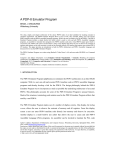
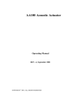
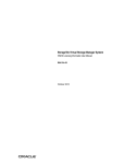
INSTALLATION AND OPERATION MANUAL
AMD SERIES
MIXER AMPLIFIERS
AMD100
AMD200
IMPORTANT SAFETY INFORMATION
PRÉCAUTIONS DURANT UTILISATION
1.
Read these instructions.
1.
LISEZ ces instructions.
2.
Keep these instructions.
2.
Tenez ces instructions.
3.
Heed all warnings.
3.
Notez tous les avertissements.
4.
Follow all instructions.
4.
Suivez toutes les avertissements.
5.
Do not use this apparatus near water.
5.
N’utilisez pas ce produit près de l’eau (la piscine, la plage, le lac, etc.).
6.
Clean only with dry cloth.
6.
Nettoyez seulement avec une étoffe sèche.
7.
Do not block any ventilation openings. Install in accordance with the
manufacturer’s instructions.
7.
Ne bloquez aucuns troux de ventilation. Installez en accord avec
les instructions du manufacturier.
8.
Do not install near any heat sources such as radiators, heat registers,
stoves, or other apparatus (including amplifiers) that produce heat.
8.
9.
Do not defeat the safety purpose of the polarized or grounding-type plug.
A polarized plug has two blades with one wider than the other.
A grounding type plug has two blades and a third grounding prong.
The wide blade or the third prong are provided for your safety. If the
provided plug does not fit into your outlet, consult an electrician for
replacement of the obsolete outlet.
N’installez près aucunes sources de chaleur comme radiateurs, registres
de chaleur, fours ou les autres équipements (y compris amplificateurs)
qui produisent la chaleur.
9.
Ne défaites pas le but de sécurité de la fiche polarisée ou base-type.
Une fiche polarisée a deux tranchants avec un plus large que l’autre.
Une fiche de base type a deux a deux tranchants et une troisième
pointe de base, le tranchant large ou la troisième pointe est fourni
pour votre sécurité. Si la fiche donnée ne conforme pas votre prise
de contact, consultez un électricien pour remplacement de la prise
de contact obsolète.
10. Protect the power cord from being walked on or pinched particularly
at plugs, convenience receptacles, and the point where they exit from
the apparatus.
11. Only use attachments/accessories specified by the manufacturer.
12. Use only with the cart, stand, tripod, bracket, or table specified by the
manufacturer, or sold with the apparatus. When a cart is used, use caution
when moving the cart/apparatus combination to avoid injury from tip-over.
13. Unplug this apparatus during lightning storms or when
unused for long periods of time.
14. Refer all servicing to qualified service personnel.
Servicing is required when the apparatus has been
damaged in any way, such as power-supply cord or plug
is damaged, liquid has been spilled or objects have fallen into the
apparatus, the apparatus has been exposed to rain or moisture, does
not operate normally, or has been dropped.
15. This appliance shall not be exposed to dripping or splashing water and
that no object filled with liquid such as vases shall be placed on the
apparatus.
16. Plug this apparatus to the proper wall outlet and make the plug to be
disconnected readily operable.
17. Main plug is used as disconnected device and it should remain readily
operable during intended use. In order to disconnect the apparatus from
the mains completely, the mains plug should be disconnected from the
mains socket outlet completely.
18. WARNING: To reduce the risk of fire or electric shock, do not expose this
apparatus to rain or moisture.
19. An appliance with a protective earth terminal should be connected to a
mains outlet with a protective earth connection.
10. Protegez le cordon de secteur contre être marchée dessus ou pincez
en particulier aux fiches, aux douilles de convenance, et au point où ils
sortent de l’appareil.
11. Seulement utilisez attachements/accessoires spécifiés par le
manufacturier.
12. Utilisez seulement avec un chariot, un stand, un trépied, un support
ou une table indiquée par le manufacturier, ou vendue avec l’appareil.
Quand un chariot est utilisé, faites attention en déplaçant la combinaison
d’appareil/chariot pour éviter de se déséquilibrer.
13. Arrachez la fiche du dispositif durant éclair et orage ou
quand pas utilisé pour longues périodes de temps.
14. Référez au personnel qualifié de service pour toutes
réparations. La réparation est donnée quand le système
a été endommagé à n’importe façon, par exemple un fil ou une fiche
endommagé(e) de la source d’alimentation. Avoir été exposé à pluie ou
humidité, n’opère pas normalement, ou avoir été tombé.
15. L’appareil ne doit pas être exposé aux écoulements ou aux éclaboussures
et aucun objet ne contenant de liquide, tel qu’un vase, ne doit être placé
sur l’objet.
16. Branchez l’appareil à une source appropriée et faire que la prise à
débrancher soit facilement accessible.
17. La prise du secteur ne doit pas être obstruée ou doit être facilement
accessible pendant son utilisation. Pour être complètement déconnecté
de l’alimentation d’entrée, la prise doit être débranchée du secteur.
18. AVERTISSEMENT: Pour éviter le risque d’incendie ou de chocs électriques,
ne pas exposer cet appareil à la pluie ou à l’humidité.
19. Un appareil avec la borne de terre de protection doit être connecté au
secteur avec la connexiion de terre de protection.
PAGE 2
AMD100/200 INSTALLATION AND OPERATION MANUAL
INTRODUCTION AND CONTENTS
AMD 100/200
INTRODUCTION
3
The AMD series of mixer amplifiers from Australian Monitor
represent a quantum leap forward in connectivity, controllability
& flexibility in the constant voltage amplifier market. The AMD
series allows a contractor to integrate the mixer amplifier to a third
party control system, enable PC control, add ICON CP control panels
for remote audio control or simply use the AMD amplifiers as
standard mixer amplifiers. Add to this the power & flexibility of
on board DSP processing & you have EQ, Dynamics, delay &
level control all available to tailor your audio system to the most
challenging of acoustic environments & deliver the highest
possible sound quality for the end user.
FRONT PANEL
4
REAR PANEL
5
THINGS TO KNOW
6
INSTALLATION & CONNECTION
7
Australian Monitor AMD series is the future of constant voltage
amplification
USING THE GUI
8–12
ICON-CP/AMD100-200
13
RS485 PROTOCOL
14–16
DIMENSIONS
17
SPECIFICATIONS
18–19
Revision 1.2 November 2010
WARNING!
TO PREVENT FIRE OR SHOCK HAZARD, DO NOT USE THE PLUG WITH
AN EXTENSION CORD, RECEPTACLE OR OTHER OUTLET UNLESS THE BLADES
CAN BE FULLY INSERTED TO PREVENT BLADE EXPOSURE.
TO REDUCE THE RISK OF FIRE OR ELECTRIC SHOCK, DO NOT EXPOSE
THIS APPLIANCE TO RAIN OR MOISTURE.
TO PREVENT ELECTRICAL SHOCK, MATCH WIDE BLADE PLUG TO WIDE SLOT, FULLY INSERT.
CAUTION
RISK OF ELECTRIC SHOCK
DO NOT OPEN
The lightning flash with arrowhead symbol,
within an equilateral triangle, is intended
to alert the user to the presence of
uninsulated “dangerous voltage” within
the product’s enclosure that may be of
sufficient magnitude to constitute a risk
of electric shock to persons.
WARNING: TO REDUCE THE RISK
OF ELECTRIC SHOCK, DO NOT
REMOVE COVER (OR BACK).
NO USER SERVICEABLE PARTS INSIDE.
REFER SERVICING TO QUALIFIED
SERVICE PERSONNEL.
The exclamation point within an equilateral
triangle is intended to alert the user to
the presence of important operating and
maintenance (servicing) instructions in the
literature accompanying the appliance.
Rating plate and caution marking are marked on the back enclosure of the apparatus
AMD100/200 INSTALLATION AND OPERATION MANUAL
PAGE 3
FRONT PANEL
STEREO BGM
AMD200
CHANNEL 1
CHANNEL 2
CHANNEL 3
CHANNEL 4
CHANNEL 5
CHANNEL 6
CHANNEL 7
1
CHANNEL 8
•
STEREO
1
•
STEREO
2
•
STEREO
3
•
STEREO
4
LEVEL
2
BASS
TREBLE
3
MASTER
4
1 Mic/Line volume controls
Used to adjust the volume of each corresponding Mic/Line Input.
Front Panel volume control and the internal “Virtual” volume control are added
together to give the overall total volume. For more information see page 6.
2 BGM Select
Mutually exclusive Background Music selection buttons. Pressing a selected
source turn BGM off.
Level control adjusts the volume of the BGM.
3 Bass and Treble Controls
Bass and Treble front panel tone control.
Bass: 10 dB of cut and boost at 200 Hz
Treble: 10 dB of cut and boost at 5 kHz
4 Master Volume
Used to adjust the master volume.
Overall master volume will always be a resultant of front panel, virtual
volume and VCA volume. For more information see page 6.
PAGE 4
AMD100/200 INSTALLATION AND OPERATION MANUAL
REAR PANEL
2
115VAC,50-60Hz
230VAC,50-60Hz
12
11
10
9
8
7
6
1 Mic/Line inputs
Balanced mic/line input connector on a 3.81 mm pluggable connector.
2 Mic/Line Dip Switches
The dip switches allow you to adjust the sensitivity or add a pad to the
corresponding input.
Only one DIP switch should be high at a time.
5
4
1
3
1
7 Logic Controls
Low Power Mode: When Low Power mode is connected to ground the
unit will enter low power mode.
Evac, Bell, Alert and Chime: When one of these pins is connected to
ground the corresponding tone will be triggered.
VCA: When a RC1 or 500 kΩ pot is connected between the VCA pin and GND
audio can be remotely controlled.
Switch 1 pads the line (-20 dB)
If a short circuit is placed between the VCA pin and GND it will result in a mute.
Switch 2 Adds 15 db of gain
Overall volume will always be a resultant of front panel, virtual volume
and VCA volume. For more information please see page 6.
Switch 3 Adds 30 db of gain
Switch 5 Adds 45 db of gain
3 Phantom Power Switches
Applies +34 VDC phantom power to the corresponding channels for electret or
condensor microphones.
VOX: The VOX output will go high when ever audio exceeds the threshold
on the selected mic channels within the GUI. the factory default has this
option turned off.
The output from the VOX output is:
+33 VDC at up to 200 mA
This can be used to drive an attenuator bypass, relay or similar to indicate
audio is present.
4 BGM RCA Inputs
4 Line level Background Music inputs on stereo RCA connectors. Stereo inputs
are summed to mono for the amplifier, but remain stereo for the line level
outputs
5 Line Level Outputs
Provides left and right line level outputs on 3.81 mm pluggable connector.
8 USB
For connection to the PC GUI. All DSP and adjustable settings are
configured via USB.
9 RS485
Used for ICON Control Panel integration and also the 3rd party control.
See page 14 for more details.
6 Phone
The phone input shares Mic/Line 2. Only one of these inputs should be used
at a time.
10 Battery Input
24 VDC input for emergency power systems.
A suitable LIU (Line Interface Unit) will need to be used for most systems
Specs:
Nominal Level Input = 0 dBu
11 Amp Outputs
100 V ,70 V, 8 ohm or 4 ohm amplifier outputs.
Bandwidth = 300 Hz to 3 kHz
12 230 V to 240 V / 115 V to 120 V
This power input is NOT auto-switching, contact Australian Monitor if the unit
needs to be changed from its shipped voltage configuration.
AMD100/200 INSTALLATION AND OPERATION MANUAL
PAGE 5
THINGS TO KNOW
Virtual Volume Controls
We have chosen to call some of the volume controls within the AMD series “Virtual
Volume” controls. This is mainly because these control sit inside the DSP of the product
but also to differentiate them from the front panel volume controls.
The “Virtual Volume’s” are controlled from either the PC GUI, 3rd Party Control or
the ICON Control Panel. The volume control in the PC GUI will move whenever one
of the controls is gestured.
The “Virtual Volume” is effectivly in series with the front panel volume control.
The resultant volume control will always be a combination of the “Virtual” and front panel
volume control providing the front panel is enabled.
If the front panel has been disabled then the only way to control volume is via the
PC GUI, 3rd Party Control or ICON Control Panels.
ATTENTION: When enabling and disabling the front panel the chance
of the output level reaching excessive levels is present. Please be sure
to mute the outputs before adjusting these options.
Updating Firmware
To update firmware inside of the AMD100/200 you will need a connection with the
PC software via USB.
All firmware files for the AMD100/200 series have a filetype of .amfw, anything else
will not be recognised by the software.
All firmware files need to be placed inside the AMD software directory:
C:/Program Files/Australian Monitor/AMD100 or AMD200/Firmware
If a .amfw file is placed in that folder then all the user needs to do is
go to Device > Update Firmware on the title bar of the GUI.
From here you can pick which firmware file you want to load into the device.
Australian Monitor suggests that you only ever update the firmware on a device when
told to by Australian Monitor Tech Support. We also suggest that you always update to
the most recent version of firmware unless told otherwise.
Default Configuration
Out of the box the AMD works as a regular mixer-amplifier. The default configuration
is as follows:
Volume controls: All set to 0 dB and Un-muted
Bass and Treble Filter: Set to 0 (flat)
Front panel Enabled
VCA Enabled
Priority Set Up:
Mic/Line 1 = Medium (Level 2)
Mic/Line 2 = Low (Level 1)
Mic/Line 3-8 = None (Level 0)
Bell = Medium (Level 2)
Chimes = Medium (Level 2)
All Tones set to -12 dB
PAGE 6
AMD100/200 INSTALLATION AND OPERATION MANUAL
INSTALLATION & CONNECTION
System Requirments
In order to use the AMD100/200 software it is recomended your computer meets the
following requirments:
CPU:
1.4 Ghz or higher
Memory:
512 MB or more
Hard Disk:
30 MB or more available
Display:
1024 x 768 (16 bit) or higher
OS:
Windows XP SP2 or later, Windows Vista, Windows 7
Other:
USB Connection
Installation
1 Log on to Windows using an account with administrator privileges.
2 Double click on “AMD.100.msi” located where you downloaded the application to.
3 Perform the installation as per the on-screen instructions.
4 After the instllation is complete a folder should be created containing all the
installation files (By default, “C:\Program Files\Australian Monitor”).
5 A shortcut will also be placed in the “Start Menu”.
Connection:
The connection between a PC and the AMD series amplifier is done over USB.
The connection is plug and play so there is minimal set up required to get up
and running.
When you first connect a USB cable to the AMD amplifier and you open the
AMD software GUI you should see in the bottom left hand corner a connection button
(See picture 1).
When the unit is first connected this should read “determining status” once this has
been completed the unit should read “Offline – Connected” (See picture 2 & 3). This tells
you that the GUI see’s an appropriate device at the end of the cable. If it reads “Offline Not Connected” then either the wrong software GUI has been used or the device cannot
be found.
Picture 1
Picture 2
Once the GUI has determined the status you can click on the connect button.
This will bring up an option window asking you if you want to either “Send” or “Retrieve”
the configuration settings (See picture 4).
Picture 3
“Send” will send the current GUI settings to the connected AMD Device.
“Retrieve” will poll the unit for its current configuration and download it to the GUI.
Once this has been done the GUI will be connected to the AMD amplifier and you will be
able to start adjusting volumes and DSP settings.
Picture 4
AMD100/200 INSTALLATION AND OPERATION MANUAL
PAGE 7
USING THE GUI
Main Screen:
The Main screen of the GUI is where most volume adjustments are made.
From here you have control over the master output, mic/line inputs and the
BGM selector.
At the base of this screen there are five set up buttons to adjust features of the
AMD series mixer amplifiers.
Audio Setup:
The Audio Setup page allows you to adjust all the DSP functions within
the AMD Series.
PAGE 8
AMD100/200 INSTALLATION AND OPERATION MANUAL
USING THE GUI
Input Level:
Each input on the AMD100/200 contains a digital trim level control, this ranges
from -96 dB to +12 dB.
There is also an invert button to reverse the phase on that input.
Input Dynamics:
Each input on the AMD100/200 contains a compressor. Threshold, Ratio, Attack,
Release and Output Gain may be adjusted.
All adjustments are displayed on the graph to the right of the screen.
Input EQ:
Each input on the AMD100/200 contains EQ. The EQ features a Low Shelf, High Shelf
and 2 parametric filters.
All adjustments are displayed on the graph to the right of the screen.
Output EQ/Filter:
Each output of the AMD100/200 contains an EQ and Crossover. The crossover allows
you to place a High Pass, Low Pass and All Pass filter on the signal. Each filter has a
frequency adjustment, the All Pass filter also contains a Q width adjustment.
From the drop down boxes below the filter adjustments you can change the filter slope,
the options are:
Butterworth 6 dB/Oct – 24 dB/Oct
Linkwitz-Riley 12 dB/Oct – 24 dB/Oct
Bessel 12 dB/Oct – 24 dB/Oct
The EQ section of the output features a High Shelf, Low Shelf and 4 parametric filters.
Both the crossover and the EQ section displayed on the graph to the right of the page.
AMD100/200 INSTALLATION AND OPERATION MANUAL
PAGE 9
USING THE GUI
Output Delay:
Each output of the AMD100/200 features delay adjustment. The adjustment is in the
range of:
Samples: 0 - 5952
Milliseconds: 0.00 – 124.00
Meters: 0.00 – 42.90
Feet: 0.00 – 140.76
Output Dynamics:
Each output of the AMD100/200 features a compressor. Threshold, Ratio, Attack,
Release and Output Gain may be adjusted. All adjustments are displayed on the
graph to the right of the screen.
Output Level:
Each output of the AMD100/200 features an output level trim. This control ranges from
-96 dB to +12 dB.
PAGE 10
AMD100/200 INSTALLATION AND OPERATION MANUAL
USING THE GUI
Priority:
The Priority window allows you to adjust which inputs have priority over others.
There are four levels of priority in the AMD Series.
Level 0 – No Priority
Level 1 – Low Priority
Level 2 – Medium Priority
Level 3 – High Priority
Level 4 – Highest Priority
When two inputs share the same level of priority they will both stay active when
the lower priority channels mute.
The threshold at which the priority will become active is adjusted via the control
at the top of the page.
All inputs will trigger from the same audio level set from the priority threshold control.
Bell and Chimes have selectable priority and can sit on any of the 5 levels.
Evac and Alert are fixed to the highest level of priority.
BGM sources are fixed to the lowest level of priority.
Tones:
The tone generator window allows you to adjust the volume of the tones
present in the AMD Series. The following tones are available:
Bell (Pre Master Level)
Chimes (Pre Master Level)
Alert (Post Master Level)
Evac (Post Master Level)
All tones volumes are by default set to -12 db.
AMD100/200 INSTALLATION AND OPERATION MANUAL
PAGE 11
USING THE GUI
VOX Output:
The VOX Output window allows you to adjust when the VOX Output is triggered and by
what sources.
The VOX Output threshold control allows you to adjust at what level the will
VOX output will trigger
The Vox logic is selectable as to which Mic/Line input it is triggered off.
By default the Vox threshold is set to -35 db with no trigger source enabled.
For more infomation about the VOX trigger output see page 5.
Enable Setup:
The Enable Setup window allows you to enable and disable VCA and Front Panel Control.
If control is active the blue light will be activated next to that option.
ATTENTION: When enabling and disabling either of these functions
the chance of the output level reaching excessive levels is present.
Please be sure to mute the outputs before adjusting these options.
The volume controls inside the AMD Mixer amplifier are in series. There for having
the GUI based volume control at a minimum but the front panel control at full will result
in no audio. See page 6 for details.
All three volume controls are in series. Overall volume will always be the resultant
of front panel, virtual volume and VCA volume.
The factory default has the front panel enabled and GUI based volume controls
set to 0db so it performs like a normal mixer amplifier.
PAGE 12
AMD100/200 INSTALLATION AND OPERATION MANUAL
ICON-CP/AMD100-200
The ICON-CP can be used to control certain functions of the AMD100/200.
The set up the control panel all you need to do is address the panel on SW1.
Switch 1-8 represent a binary address. For example to address it to ID1 all you
need to do is have number 1 on, to address it to 3 have switch 1 and 2 on.
1. BGM 1
SW2 C and D do not do anything, A and B adjust the LED settings of the panel.
With switch A high ambient light adjustment will be turned on. With switch B on,
low brightness mode will be activated. Only one switch should be up at a time.
3. BGM 3
2. BGM 2
4. BGM 4
5. BGM Off
ID 1:
6. BGM Mute
In this mode the first 5 buttons act as a source select (1-4 and off)
7. BGM Vol +
The 6th button acts as a mute control
Buttons 7 and 8 are volume up and volume down for the BGM source
8. BGM Vol -
NOTE:
BGM Off deselects all the BGM input.
BGM Mute toggles and maintains the selected BGM source for easy unmuting.
1. Mic\Line 1
2. Mic\Line 2
ID 2:
3. Mic\Line 3
In this mode the panel acts as 6 individual volume controls.
4. Mic\Line 4
The first 6 buttons pick the volume you want to control and the bottom two buttons are
volume up and volume down.
5. BGM
6. Master
+ Volume
- Volume
1. Mic\Line 5
2. Mic\Line 6
ID 3:
3. Mic\Line 7
This mode is the same as two but controls different sources.
Note, this is will work on AMD200 only.
4. Mic\Line 8
5. BGM
6. Master
+ Volume
- Volume
AMD100/200 INSTALLATION AND OPERATION MANUAL
PAGE 13
RS485 PROTOCOL
Port & Protocol Information
Virtual Volume Controls:
The AMD100/200 has a RJ45 connector on the rear of the unit. This
connector is used for the ICON-CP control panel and also for controlling the
device with an external control system via RS485.
To adjust the virtual volume control of the mic/line inputs, BGM source or
Master.
Below is the pinout of the RJ45:
%PVAL:xxyy<CR>
“xx” represents the parameter ID to be adjusted and “yy” is the new value.
Pin 1 = NC
Pin 2 = GND
Parameter ID’s
01 = Mic/Line 1 Volume
Pin 3 = RS485-A
02 = Mic/Line 2 Volume
Pin 4 = Power (+33 VDC, supplied by AMD100/200 up to 500 mA)
03 = Mic/Line 3 Volume
Pin 5 = Power (+33 VDC, supplied by AMD100/200 up to 500 mA)
04 = Mic/Line 4 Volume
Pin 6 = RS485-B
05 = Mic/Line 5 Volume
Pin 7 = GND
06 = Mic/Line 6 Volume
Pin 8 = NC
07 = Mic/Line 7 Volume
All parameters are constantly updated in the AMD100/200. If a control is
adjust by another source e.g. ICON-CP all control devices will be update
(3rd Party control and PC Gui).
08 = Mic/Line 8 Volume
Baud rate: 19200
0C = Master Volume
Bits: 8
Parity: No
The value of yy can range between 0x00 (off) and 0xE1 (225 = +12 dB of
gain). This allows half dB steps throughout the range where for example:
Stop bits: 1
0x00 = Off
The protocol is an ASCII protocol – all characters in the string are ASCII chars.
Abinary value ranging between hexadecimal 00 and FF is transmitted as two
ASCII chars. All command strings start with the % character and end with a
carriage return – shown as <CR> in this document and equal to the single
ASCII value of 13 (0x0D).
0x01 = -100 dB
09 = Stereo BGM Volume
0xC9 = 0 dB
0xE1 = +12 dB
To request the current level of a source:
%PVAL:xx??<CR> where “xx” is the source.
Available Parameters
The following parameters can be externally controlled:
Mic/Line Input 1 - 8 (1 - 4 for AMD100), BGM source and Master virtual
volume control.
When a volume is adjusted from another source e.g. ICON-CP the
AMD100/200 will send:
%PVAL=xxyy<CR> where “xx” is the source and “yy” is the
current value.
Mic/Line input 1-8 (1 - 4 for AMD100), BGM source and Master mute.
BGM Source select
Low Power Mode
Virtual filter control (bass and treble)
Filter bypass (bass and treble)
Power amp fault indication
PAGE 14
AMD100/200 INSTALLATION AND OPERATION MANUAL
RS485 PROTOCOL
Virtual Mute Flags
BGM Source Select
To toggle the mute control of Mic/Line 1-8, BGM source or Master.
To select a BGM source.
%PFLG:xxyy<CR>
%PSRC:xx<CR>
“xx” represents the parameter ID to be adjusted and “yy” is the new value of
the flag.
“xx” represents the source you want to select.
Parameter ID’s
01 = BGM 1
01 = Mic/Line 1 Mute Flag
02 = BGM 2
02 = Mic/Line 2 Mute Flag
03 = BGM 3
03 = Mic/Line 3 Mute Flag
04 = BGM 4
04 = Mic/Line 4 Mute Flag
The request the current value of the mute flag:
05 = Mic/Line 5 Mute Flag
06 = Mic/Line 6 Mute Flag
00 = Off
%PSRC:??<CR>
07 = Mic/Line 7 Mute Flag
If the BGM source is changed from another source e.g. ICON-CP
the AMD100/200 will send:
08 = Mic/Line 8 Mute Flag
%PSRC=xx<CR> where “xx” represents the current source
09 = Stereo BGM Mute Flag
0C = Master Mute Flag
The value of “yy” should either be 00 or 01.
00 = Unmuted
01 = Muted
To request the current value of the mute flag:
%PFLG:xx??<CR> where “xx” is the source
If a mute flag is enabled from another source e.g. ICON-CP the AMD100/200
will send:
%PFLG=xxyy<CR> where “xx” is the source and “yy” is the current
value
Low Power Mode
To place the enable or disable “low power mode”
%PGRN:xx<CR>
“xx” represents whether the unit is in low power
mode of not.
00 = Normal Mode
01 = Low Power Mode
02 = Emergency Mode
03 = Emergency Mode with Low Power Mode
To request the current value:
%PGRN:??<CR>
The device will respond with:
%PGRN=xx<CR> where “xx” is the current state
AMD100/200 INSTALLATION AND OPERATION MANUAL
PAGE 15
RS485 PROTOCOL
Virtual Filter Controls
Power Amp Fault Indication
To adjust the virtual filter control of the master Treble and bass controls.
To poll the unit for its current fault status
%PVAL:xxyy<CR>
“xx” represents the parameter ID to be adjusted and “yy” is
the new value.
Parameter ID’s
0A = Bass Filter
0B = Treble Filter
The value of “yy” can span between 0x00 (10 dB of cut) and 0x14
(10 dB of boost)
To request the current level of a source:
%PAMP=??<CR>
The AMD100/200 will respond with.
%PAMP=xx<CR>
“xx” represents whether the unit is in amplifier fault mode
00 = Amp is running in normal mode
01 = Amp is in thermal shutdown
02 = Amp is in fault shutdown
The PAMP command is a polled command, the AMD100/200 will not send
data regarding the amp status unless explicitly requested to do so.
%PVAL:xx??<CR> where “xx” is the source.
When a filter is adjusted from another source e.g. the GUI the AMD100/200
will send:
%PVAL=xxyy<CR> where “xx” is the source and “yy” is the current
value.
To request the current level of a source:
%PVAL:xx??<CR> where “xx” is the source.
Filter Bypass Flag
To toggle the bypass control of the bass and treble filters.
%PFLG:xxyy<CR>
“xx” represents the parameter ID to be adjusted and “yy” is
the new value of the flag.
Parameter ID’s
0A = Bass Filter
0B = Treble Filter
The value of “yy” should either be 00 or 01.
00 = Filter Inline
01 = Bypassed Operation
To request the current value of the mute flag:
%PFLG:xx??<CR> where “xx” is the source
If a mute flag is enabled from another source e.g. ICON-CP the AMD100/200
will send:
%PFLG=xxyy<CR> where “xx” is the source and “yy” is the
current value
PAGE 16
AMD100/200 INSTALLATION AND OPERATION MANUAL
44.00 mm
(1.75”)
DIMENSIONS
32.00 mm
(1.25”)
482.00 mm (19.0”)
465.00 mm (18.3”)
STEREO BGM
AMD200
CHANNEL 1
CHANNEL 2
CHANNEL 3
CHANNEL 4
CHANNEL 5
CHANNEL 6
CHANNEL 7
CHANNEL 8
•
STEREO
1
•
STEREO
2
•
STEREO
3
•
STEREO
4
LEVEL
BASS
TREBLE
MASTER
430.00 mm (16.9”)
115VAC,50-60Hz
230VAC,50-60Hz
330.00 mm (13.0”)
AMD100/200 INSTALLATION AND OPERATION MANUAL
PAGE 17
SPECIFICATIONS
Specification
Conditions
Frequency response:
Mic/Line Inputs ----->Line Level Output
Mic/Line Inputs ----->Amp Output
Stereo Inputs ---->Line Level Output
Stereo Inputs ---->Amp Output
20-20 kHz, -3 dB
60-20 kHz, -3 dB
20-20 kHz, -3 dB
60-20 kHz, -3 dB
Signal Input -2 dB below clip
Signal Input -2 dB below clip
Signal Input -2 dB below clip
Signal Input -2 dB below clip
Total Harmonic Distortion:
Mic/Line Inputs ----> Line Level Output
Mic/Line Inputs ----> Line Level Output
Mic/Line Inputs ---> Amp Output
Stereo Inputs ---> Line Level Output
Stereo Inputs ----> Amp Output
<0.05 %
<0.1 %
<0.5 %
<0.05 %
<0.5 %
Input Impedance:
Mic/Line
Mic:
Line:
Stereo Input
Max Input
Mic/Line Input
Stereo Input
Mic/Line Pad Switch:
Maximum Voltage Gain:
Mic/Line Inputs
0 dB gain, Signal input -2 dB below clip
45 dB gain, Signal input -2 dB below clip
Signal input -2 dB below clip
Signal input -2 dB below clip
Signal input -2 dB below clip
1.5 k
1.5 k
12 k
22 dBu
2 dBu
6 dBu
Mic/Line pad on
Mic/Line pad off
20 dB pad
45 dB
With 45 dB gain switch (analog domain)
Phantom Power:
+34 VDC
Available via individual switch on each mic/line channel
Cross Talk:
> 80 dB
1 kHz, input channel at clip, measured on line output of adjacent output
S/N Ratio:
Mic\Line Input
Stereo Input
> 92 dB
> 91 dB
A-weighted, to line and amp output, 20 Hz to 20 kHz
A-weighted, to line and amp output, 20 Hz to 20 kHz
Max Output
Line Level Ouptut
10 dBu
Balanced (+4 dBu unbalanced on each leg)
PAGE 18
AMD100/200 INSTALLATION AND OPERATION MANUAL
SPECIFICATIONS
Specification
Conditions
Power Output - AMD100
4 ohm
8 ohm
70 V
100 V
100 W
100 W
100 W
100 W
20 Vrms
28.28 Vrms
Power Output - AMD200
4 ohm
8 ohm
70 V
100 V
200 W
200 W
200 W
200 W
28.28 Vrms
40 Vrms
Power Consumption - AMD100
Green
Idle
1/8th Power
1/3rd Power
9W
15 W
32 W
60 W
No control panel attached, 4 Ohm load
No control panel attached, 4 Ohm load
No control panel attached, 4 Ohm load
No control panel attached, 4 Ohm load
Power Consumption - AMD200
Green
Idle
1/8th Power
1/3rd Power
9W
15 W
48 W
83 W
No control panel attached, 4 Ohm load
No control panel attached, 4 Ohm load
No control panel attached, 4 Ohm load
No control panel attached, 4 Ohm load
Thermal Dissipation - AMD100
Idle
1/8th
15 W (51.18 Btu\Hr)
18.86 W (64.32 Btu\Hr)
Pink noise 12 dB crest factor, typical of program music just before clip
Thermal Dissipation - AMD200
Idle
1/8th
15 W (51.18 Btu\Hr)
24.25 W (82.74 Btu\Hr)
Pink noise 12 dB crest factor, typical of program music just before clip
Power Source
AC Mains (230 V to 240 V / 115 V to 120 V) or +24 VDC
Recommended Operating Temp
Recommended Operating Humidity
10° C to 45° C (50° F to 113° F)
5 % to 95 %
Dimensions (w x d x h)
430 mm x 330 mm x 44 mm
(16.9” x 13” x 1.75”)
Net Weight - AMD100
- AMD200
6 kg (13.2 lbs)
7 kg (15.4 lbs)
Shipping Weight - AMD100
- AMD200
8 kg (17.6 lbs)
9 kg (19.8 lbs)
Shipping Dimensions (w x d x h)
AMD100/200 INSTALLATION AND OPERATION MANUAL
Not including rack ears or front panel knobs
540 mm x 410 mm x 140 mm
(21.3” x 16.1” x 5.51”)
PAGE 19
ENGINEERED BY AUSTRALIAN MONITOR
Address: 1 Clyde Street, Silverwater, Sydney NSW 2128 Australia. Private Bag 149, Silverwater NSW 1811 ABN 78 001 345 482
Website: www.australianmonitor.com.au International enquiries email: [email protected]
DISTRIBUTED IN AUSTRALIA AND NEW ZEALAND BY HILLS SVL www.hillssvl.com.au
NSW
P: 02 9647 1411
E: [email protected]
QLD
P: 07 3852 1312
E: [email protected]
ACT
P: 02 6260 4544
E: [email protected]
WA
P: 08 9204 0200
E: [email protected]
VIC
P: 03 9890 7477
E: [email protected]
SA
NZ
P: 08 8408 8300
P: 09 415 9426
E: [email protected] E: [email protected]