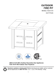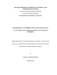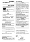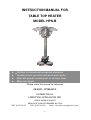
1
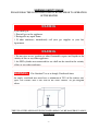
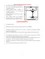
INSTRUCTION MANUAL FOR
TABLE TOP HEATER
MODEL HPS-B
★
★
★
★
Certified to international recognized standards.
Variable control gas valve with piezo push igniter.
Steel with powder coated green or stainless steel.
88cm total height.
Please retain this manual for reference
CE 0407 – 27750/441/C
DISTRIBUTED BY
LIFESTYLE APPLIANCES LTD
UNIT66 ENFIELD IND EST
REDDITCH ,WORCESTERSHIRE, B97 6DE
TEL : 01527 65126
FAX : 01527 584523
-0-
Email : [email protected]
TABLE OF CONTENTS
ITEM DESCRIPTION
1
. WARNING SAFETY RULES······················································· 1
2
. READ SAFETY REQUIREMENTS BEFORE OPERATION········ 2
3
. SAFETY RULES FOR OUTDOOR GAS APPLIANCE················ 3
4
. TABLE HEATER STAND AND LOCATION································· 4
5
. GAS REQUIREMENTS······························································
6
. PROCEDURE FOR LEAKAGE TEST········································· 5
7
. OPERATION AND STORAGE···················································· 6
8
. PARTS AND SPECIFICATION···················································· 7
9
. ASSEMBLY PARTS···································································· 8
10
. ASSEMBLY PROCECDURE······················································ 9
11
. PROBLEMS CHECK LIST·························································· 12
4
Copyright Information
All rights reserved. No part of this manual may be reproduced, transmitted, stored in
a retrieval system, or translated into any language in any form by any means,
mechanical, optical, electronic, recording, or otherwise without the written
permission of Changzhou Gardensun Furnace Co., Ltd.
Changzhou Gardensun Furnace Co., Ltd. Reserves the right to revise this manual and
to make changes to any or all parts at any time, without obligation to notify any
person or entity of such revisions and changes.
Copyright Changzhou Gardensun Furnace Co., Ltd.
2005 Edition the front page
-1-
WARNING SAFETY RULES
PLEASE READ THE FOLLOWING SAFETY RULES PRIOR TO OPERATION
OF THE HEATER
WARNING
If you smell gas:
1. Shut off gas to the appliance.
2. Extinguish any open flame.
3. If odor continues, immediately call your gas supplier or your fire
department.
WARNING
1. Do not store or use gasoline or other flammable vapors and liquids in the
vicinity of this or any other appliance.
2. An LPG cylinder not connected for use shall not be stored in the vicinity
of this or any other appliance.
WARNING:
For Outdoor Use or in Amply Ventilated Areas
An amply ventilated area must have a minimum of 25% of the surface area
open. The surface area is the sum of the walls surface. As per diagram
below.
THE USE OF THIS APPLIANCE IN ENCLOSED AREAS CAN BE DANGEROUS AND IS
PROHIBITED
-2-
WARNING: Improper installation, adjustment, alteration, service or maintenance
can cause injury or property damage. Read the installation, operating and maintenance
instructions thoroughly before installing or servicing this equipment.
READ SAFETY REQUIREMENTS BEFORE OPERATION
☆
The installation must conform with local codes or, in the absence of local codes, with either
☆
This outdoor gas appliance is not intended to be installed in or on recreational vehicles and/or
☆
Maintain proper clearances from combustible construction the specific minimum clearances
☆
Inspect the hose before each use of the outdoor gas appliance.
the National Fuel Gas Code, Propane Installation Code.
boats.
from such construction to the sides and back of the outdoor gas appliance.
If it is evident there is excessive abrasion or wear out, or the hose is cut, it must be replaced
prior to this outdoor gas appliance being put into operation. The replacement hose assembly
shall be that specified by the manufacturer.
☆
Properly locating the gas hose, including locating the hose out of pathways where people may
☆
Maintenance Instruction
trip over it or in areas where the hose may be subject to accidental damage.
Keeping outdoor gas appliance area clear and free from combustible materials, gasoline
and other flammable vapors and liquids.
Not obstructing the flow of combustion and ventilation air.
Keeping the ventilation opening(s) of the cylinder enclosure free and clear from debris.
Visually checking burner flames.
Cleaning this outdoor gas appliance, including special surfaces, with recommended
cleaning agents, if necessary.
Checking and cleaning burner tubes for insects and insect nests, A clogged tube can lead
to a fire beneath the grill.
☆
Maintain adequate clearance around air openings into the combustion chamber, clearances
from combustible material, provisions accessibility and for combustion and ventilating air
supply.
☆
Certain materials or items, when stored under the appliance, will be subjected to radiant heat
and could be seriously damaged.
-3-
WARNING:
1. Children and adults should be alerted to the hazards of high surface temperatures
and should stay away to avoid burns or clothing ignition.
2. Young children should be carefully supervised when they are in the area of the
heater.
3. Clothing or other flammable materials should not be hung from the heater, or
placed on or near the heater.
4. Any guard or other protective device removed for servicing, the appliance must
be replaced prior to operating.
5. Installation and repair should be done by a qualified service person. The heater
should be inspected before use and at least annually by a qualified service person.
More frequent cleaning may be required as necessary. It is imperative that control
compartment, burners and circulating air passageway of the appliance be kept
clean.
SAFETY RULES FOR OUTDOOR GAS APPLIANCE
☆
This outdoor gas appliance shall be used only outdoors and shall not be used in a building,
☆
If this outdoor gas appliance is not use, the gas must be turned off at the supply cylinder.
garage or any other enclosed area.
Storage of this outdoor gas appliance indoors is permissible only if the cylinder is
disconnected and removed from the outdoor cooking gas appliance.
Cylinders must be stored outdoors in a well-ventilated area out of the reach of children
and must not be stored in a building, garage or any other enclosed area.
☆
The clip on propane gas regulator and hose assembly supplied with this outdoor gas
appliance must be used. Replacement pressure regulators and hose assemblies must be those
specified by the manufacturer.
☆
The cylinder supply system must be arranged for vapor withdrawal.
☆
The cylinder used must include a collar to protect the cylinder valve.
-4-
TABLE HEATER STAND AND LOCATION
☆
The garden table heater is for outdoor use
only. Always ensure that adequate fresh air
ventilation is provided.
☆
Always
maintain
proper
clearance
combustible materials, i.e. top
to
45 cm and
sides 60 cm minimum.
☆
Garden table heater must be fixed on a stable
☆
Never
and strong table.
operate heater
in
an
explosive
atmosphere like in areas where gasoline or
other flammable liquids or vapors are stored.
GAS REQUIREMENTS
☆
Use propane gas only.
☆
Maximum inlet pressure of propane regulator must not exceed 100 PSI.
☆
A minimum supply pressure of 28 cm (11”) W.C. is required for the purpose of input
☆
The pressure regulator and hose assembly to be used must conform to local standard codes.
☆
The installation must conform to local codes, or in the absence of local codes, with the
☆
A dented, rusted or damaged propane tank may be hazardous and should be checked by your
☆
The propane tank must be arranged to provide for vapor withdrawal from the operating
☆
Never connect an unregulated propane tank to the heater.
adjustment for propane gas.
standard for the storage and handling of liquid petroleum gases.
tank supplier.
Never use a propane tank with a damaged valve connection.
cylinder.
-5-
PROCEDURE FOR LEAKAGE TEST
NEVER CONNECT AN UNREGULATED GAS SUPPLY TO APPLIANCE
PRECAUTIONS
☆
Periodically check the whole gas system for leaks.
☆
Immediately check for leaks if smell of gas is detected.
☆
Extinguish all open flames during leakage test or when smell of gas is detected.
☆
Never smoke while performing leak test.
☆
If you cannot stop a leak, turn off the gas supply immediately and contact the dealer where
☆
The appliance must be checked with a full gas tank.
you bought your heater unit, or your gas supplier.
DO NOT use the heater until you have performed leak test on all the connections and verified
that your unit does not leak.
☆
Use only parts recommended by the manufacturer. Substitution can void the warranty.
TESTING FOR GAS LEAKAGE
Gas connections on the appliance are leak tested at the factory prior to shipment. Possible
mishandling of the appliance during the shipment might contribute to product integrity as a whole.
A complete gas leakage test must be performed again at the installation site. Please follow the
procedure below for leakage test.
☆
Make a soap solution of one part liquid detergent and one part water. The soap solution can
☆
Make sure the safety control valve is in the “OFF” position.
☆
Turn ON the gas supply and check for bubbles from the hoses and connections. Prescence of
☆
If a leak is present, turn OFF the gas supply immediately, tighten any leaking fitting, turn gas
be applied with spray bottle, brush or rag. Soap bubbles will appear where a leak is present.
bubbles means that a gas leak is present.
supply ON and recheck.
-6-
VISUALLY CHECKING BURNER FLAMES
The flame pattern at the emitter grid should be visually checked whenever the appliance is operated.
Under the following conditions the appliance should be turned off immediately and NOT operated
again until repair are made:
When the pilot flame extends more than 1/2 inch beyond surface of the emitter grid.
When black soot accumulates on the emitter grid.
OPERATION AND STORAGE
TO TURN ON THE HEATER
1. Turn on the gas supply at the regulator by turning the lever on the regulator to the
“ on “ position. This is after you have correctly fixed your regulator to your gas bottle.
2.
Firmly press down and turn the variable control knob for approximately
45°(counter anti-clockwise).
3.
Press down the variable control knob and hold for 20 seconds. while holding
down the variable control knob, press the igniter button several times until
the pilot flame comes on. Release the variable control knob after the pilot flame lights.
4.
If the pilot does not light, repeat step 2 to 3.
Note: If a new tank has just been connected, please allow at least one minute for the air in
the gas pipeline to purge out through the pilot hole.
5.
After the flame comes on , leave the variable control knob at minimum position for about 5
minutes, then switch to a desire temperature position.
TO TURN HEATER AND PILOT OFF
1. Turn control knob to “ON” position.
2. Then , press down lightly and turn to “OFF” position.
3. Turn the gas tank off completely.
Variable Control Knob
TO STORE THE HEATER UNIT
1. Turn the gas tank to complete closed position.
2. Remove the pressure regulator and the hose attachment.
3. Inspect the gas tank for damage. If you suspect that your tank is damaged, return it to your
gas tank supplier.
4.
Store the gas tank in a well-ventilated area. Never store the gas tank below ground(for
example, basement).
-7-
CLEANING AND CARE
1. Wipe off tarnished surfaces with soft, moist rag.
2. Do not use harsh chemical or abrasives to clean the heater housing. If necessary, use mild
detergent.
Improper Lighting Procedures May Cause Personal Injury Or Property Damage.
-8-
PARTS AND SPECIFICATION
• TANK COVER AND MOBILE STAND ARE NOT SUPPLIED AND ARE
FOR ILLUSTRATIVE PURPOSES ONLY *
-9-
A.Construction and characteristics
☆
Gas heater for garden table
☆
Textile tank cover(optional)
☆
Gas hose with metal screw clips
☆
Stainless steel flame screen
☆
Heat emission from reflector
B. Specification
☆
For outdoor use only
☆
Uses propane gas only
☆
Max. wattage: 4,000 Watts
☆
Heat capacity: 13,600 BTU
☆
Weight: 8.6kgs
☆
Height: 880 mm approx
☆
With CSA & CE certificate
C.Table of openings
Gas pressure (mbar)
Main opening
Opening of pilot burner
≤50
0.9mm
0.18 mm
ASSEMBLY PARTS
Tools needed:
- 10 -
☆
Adjustable opening wrench (2) 20 cm long
☆
Slip joint pliers 23 cm long
☆
Philips screwdriver w/ medium blade
☆
Teflon plumbing tape for joints
☆
Spray bottle of soap solution for leakage test
Other parts supplied:
☆
3 pcs M6 castle nuts
☆
4 pcs M6×16mm bolts
☆
4 pcs M4×8 mm bolts
☆
9 pcs ∅6 mm washers
☆
Reflector ∅535 x (D)100 mm
ASSEMBLY PROCEDURE
STEP 1:
1-1.
Put the base and cast iron block under the main body in
the picture.
1-2.
Use 4 pcs M6×16 mm bolts to join the base & cast iron
Main body
block and the main body.
1-3.
Tighten each of the bolts.
Base
Cast iron block
STEP 2:
Bolt
STEP 1
Supporting bolt
- 11 -
2-1.
Join 3pcs supporting bolts & 3pcs washers to the
burner mesh.
washer
Flame screen
2-2.
Put the burner mesh into burner base.
2-3.
Use 4 pcs M4×8 mm stainless steel bolts to join the
Bolt
burner mesh and the base as shown.
2-4.
Tighten each of the bolts.
STEP 2
STEP 3:
3-1.
Put the protection guard over the burner mesh and align
with the 4-Ø3mm holes around the base as shown.
Protection net
Hole
STEP 3
STEP 4:
4-1.
Set 3 pcs washers above the 3 pcs supporting bolts.
4-2.
Put reflector canopy onto the top of flame screen
Reflector
aligning through the 3 pcs supporting bolts.
washer
STEP 4
- 12 -
STEP 5:
5-1.
Place 3 pcs castle nuts & 3 pcs washers on each
5-2.
Tighten each of the castle nuts.
STEP 6:
6-1.
Castle nut
washer
reflector supporting bolts.
STEP 5
Connect the LPG gas hose to the table heater gas inlet
connector with a threaded clip.
6-2.
Tighten the clip.
Loop
LPG gas hose
STEP 6
STEP 7:
- 13 -
7-1.
Connect the regulator to the other end of the gas hose
and connect it to your LPG gas tank.
TANK COVER AND MOBILE STAND ARE ONLY
AVAILABLE
AND
APPROVED
FOR
THE
AMERICAN MARKET AND AS SUCH ARE NOT
RELVANT FOR SUPPLIES INTO THE EUROPEAN
Tank cover
UNION.
Tank
(not included)
Mobile stand
STEP 8:
8-1.
STEP 7
Adjust the gas tank to advisable position, for example
under the table.
YOU MUST PERFORM A GAS LEAK TEST PRIOR
TO USING YOUR HEATER
(Table)
STEP 8
- 14 -
PROBLEMS CHECK LIST
PROBLEM
PROBABLE CAUSE
SOLUTION
Pilot will not light
Gas valve maybe OFF
Turn the gas valve ON
Tank fuel empty
Refill LPG tank
Opening blocked
Clean or replace opening
Air in supply system
Purge air from lines
Loose connections
Check all fittings
Debris around pilot
Clean dirty area
Loose connections
Tighten connections
Thermocouple bad
Replace thermocouple
Gas leak in line
Check connections
Lack of fuel pressure
Tank near empty. Refill LPG tank.
Pressure is low
Tank near empty. Refill LPG tank.
Opening blocked
Remove and clean
Control not ON
Turn valve to ON
Thermocouple bad
Replace thermocouple
Pilot light assembly bent
Place pilot properly
Not in correct location
Position properly and retry
Pilot will not stay on
Burner will not light
Manufactured by:
Changzhou Gardensun Furnace Co., Ltd.
No. 1, Boyi Town, Changzhou City,
Jiangsu Province P.R. China
Tel: 86-519-3317471
Fax: 86-519-3315116
MODEL
HPS-B
Destination Countries
BE-CH-ES-FR-GB-IE-IT-PT
Category
I3+
M/bar
28-30/37
Power
4.0 Kw
CE 0407
Certificate No: 27750/441/C
To BSEN : 14543:2002
- 15 -